

Page 1
Specifications
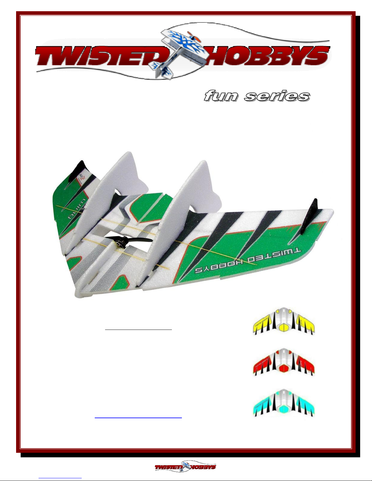
30” Crack Wing
By
RC
RC Factory
RCRC
Factory
FactoryFactory
Wing span – 30” / Length – 14”
AUW 90 - 100g
2000-2800kV outrunner motor (11g – 18g)
6 - 12 amp ESC / 2s 180 – 250mAh battery
4 ch radio with Elevon Mixing
2x 4g to7g servos / 6x3 to 7x3.5 prop
Twisted Hobbys
www.twistedhobbys.com
Rev: 2013.02.02.v001b
USA Distributor
1
Page 2
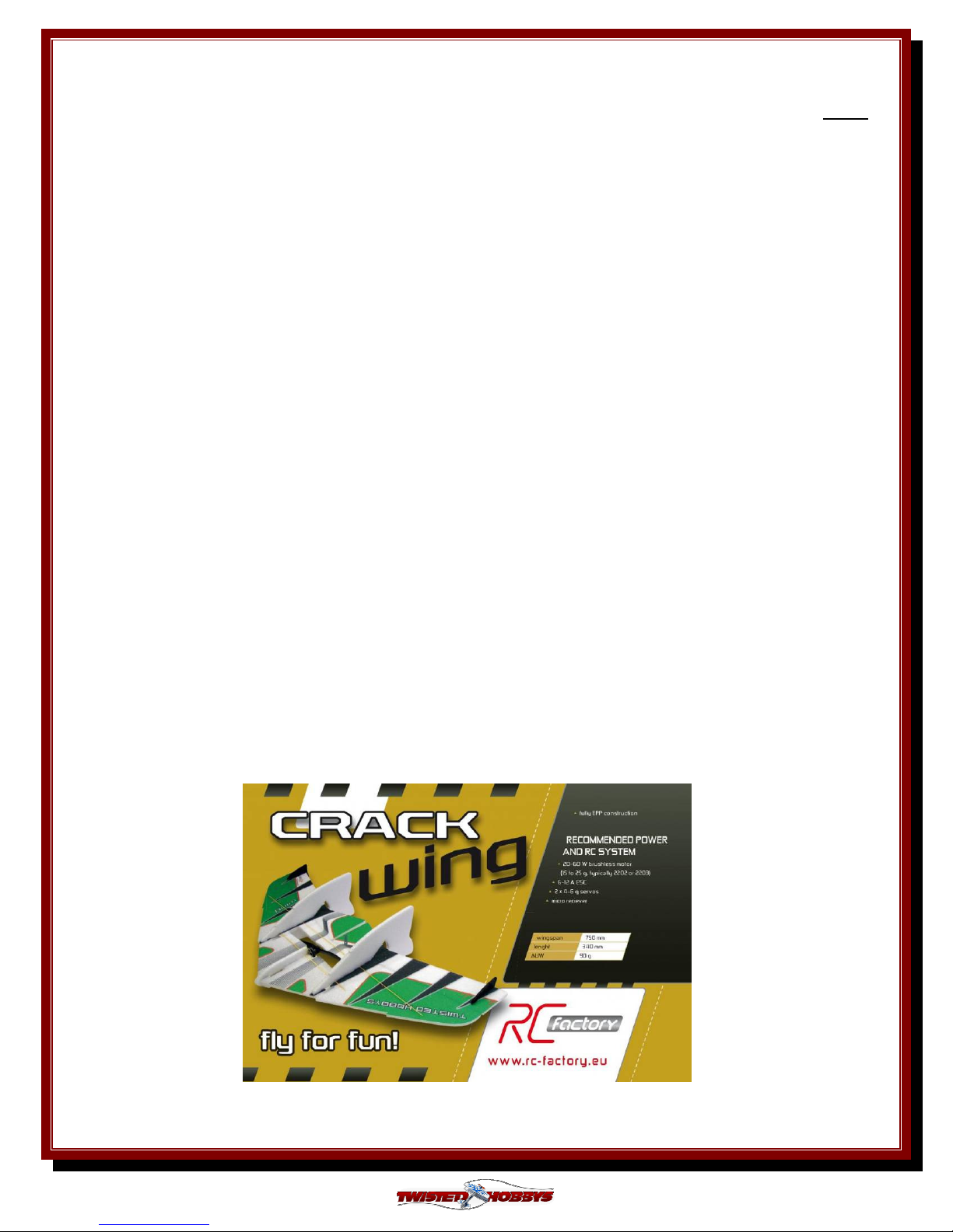
TABLE OF CONTENTS
Page
WARNING INFORMATION...................................................................................................................................................3
SHIPPING DAMAGE ............................................................................................................................................................... 3
OUR MISSION ..........................................................................................................................................................................3
SAFETY NOTES .......................................................................................................................................................................4
IMPORTANT: PRIOR TO ANY ASSEMBLY ..............................................................................................................4
KIT CONTENTS .......................................................................................................................................................................5
OPTIONAL PARTS ..................................................................................................................................................................6
TOOLS & ADHESIVES NEEDED..........................................................................................................................................7
THE BUILD ............................................................................................................................................................................... 8
CENTER OF GRAVITY ........................................................................................................................................................ 38
CONTROL THROWS ............................................................................................................................................................39
3D / Combat Flight .......................................................................................................................................................... 39
Sport .................................................................................................................................................................................39
PRE-FLIGHT & TESTING ...................................................................................................................................................40
P
REFLIGHT CHECKS
Motor................................................................................................................................................................................40
Flight Controls .................................................................................................................................................................40
Batteries ........................................................................................................................................................................... 40
Radio ................................................................................................................................................................................40
Range Check.....................................................................................................................................................................40
F
LIGHT TESTING
S
TORAGE
............................................................................................................................................................................... 40
............................................................................................................................................................... 40
....................................................................................................................................................................40
NOTES & S/U SHEET ............................................................................................................................................................41
TIPS AND TRICKS ................................................................................................................................................................42
Rev: 2013.02.02.v001b
2
Page 3

TWISTED HOBBYS
Website: www.twistedhobbys.com – email: sales@twistedhobbys.com
Thank you for your purchasing a Twisted Hobbys’ model. Please read through the entire manual before
beginning to build this model. If you have any questions please contact us at the above indicated email address.
WARNING INFORMATION
WARNING INFORMATION
WARNING INFORMATIONWARNING INFORMATION
This R/C Aircraft is not a toy! Read and understand the entire manual before assembly. If misused, it can
cause serious bodily harm and property damage. Fly only in open areas, and AMA (
Aeronautics
by other manufactures’ products. If you are not an experienced pilot and airplane modeler you must use the
help of an experienced pilot or an authorized flight instructor for the building and flying of this model aircraft.
These instructions are suggestions only on how to assemble this model. There are other ways and methods to
do so. Twisted Hobbys has no control over the final assembly, the materials and accessories used when
assembling this kit, or the manner in which the assembled model, installed radio gear and electronic parts are
used and maintained. Thus, no liability is assumed or accepted for any damage resulting from the use of the
assembled model aircraft or from this instruction manual including but not limited to direct, indirect,
incidental, special, and consequential damages. By the act of using this user-assembled product, the user
accepts all resulting liability. In no event shall Twisted Hobbys’ liability exceed the original purchase price of
the kit.
) approved flying sites. Do not over look the warnings and instructions enclosed or those provided
Academy of Model
SHIPPING DAMAGE
SHIPPING DAMAGE
SHIPPING DAMAGESHIPPING DAMAGE
Twisted Hobbys checks each plane before shipping to ensure that each kit is in fine condition. We have no
bearing on the condition of any component parts damaged by use, modification, or assembly of the model.
Inspect the components of this kit upon receipt. If you find any parts damaged or missing, contact Twisted
Hobbys immediately. We will not accept the return or replacement of parts on which assembly work has already
begun. Twisted Hobbys reserves the right to change this warranty at anytime without notice.
OUR
OUR MISSION
To provide the best products and service to our customers at the lowest prices possible.
We take great pride in our company, our commitment to customer service and in the
products we sell. Our online store is designed to provide you with a safe and secure
environment to browse our product catalog.
OUR OUR
MISSION
MISSIONMISSION
Thank you for shopping with Twisted Hobbys!
Thank you for shopping with Twisted Hobbys!
Thank you for shopping with Twisted Hobbys!Thank you for shopping with Twisted Hobbys!
Rev: 2013.02.02.v001b
3
Page 4

SAFETY NOTES
SAFETY NOTES
SAFETY NOTESSAFETY NOTES
Before assembling and flying this model, read carefully any
instructions and warnings of other manufacturers for all the
products you installed or used on your model, especially radio
equipment and power source.
Check thoroughly before ever flight that the airplanes’
components are in good shape and functioning properly. If you
find a fault do not fly the model until you have corrected the
problem.
Radio interference caused by unknown sources can occur at any
time without notice. In such a case, your model will be
uncontrollable and completely unpredictable. Make sure to
perform a range check before every flight. If you detect a control
problem or interference during a flight, immediately land the
model to prevent a potential accident.
Youngsters should only be allowed to assemble and fly these
models under the instruction and supervision of an experienced
adult.
Do not operate this model in a confined area.
Do not stand in line with, or in front of a spinning propeller and
never touch it with any object.
IMPORTANT: PRIOR TO ANY ASSEMBLY
Please Note: after removing kit from shipping box, lay
each piece flat on a hard surface, this will allow the
airframe to straighten out if lightly bent from
shipping. Do not worry since EPP is very pliable and
can be bent back if out of shape.
Rev: 2013.02.02.v001b
4
Page 5
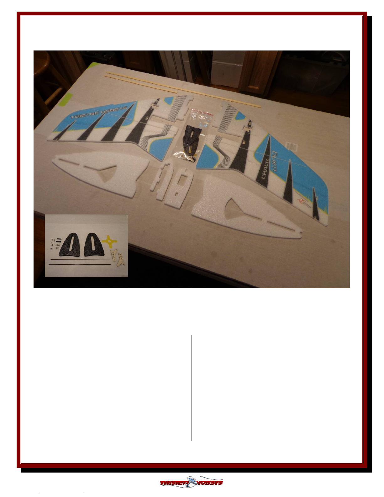
kit contents
kit contents
kit contentskit contents
3 0 ” C r a c k W i n g
standard parts list:
2x – wing half
2x – side fin/rudder
1x – fuselage (3 parts)
1x – 1.5mm x 7.0mm x 290mm wing spar
1x – 1.5mm x 7.0mm x 600mm wing spar
hardware packet:
2x – 1.0mm dia x 130mm push rod
2x – wood horns
2x – heat shrink tubing pieces
2x – z-bend wires
2x – quick connectors
1x – motor mount
Rev: 2013.02.02.v001b
5
Page 6
OPTIONAL PARTS
OPTIONAL PARTS
OPTIONAL PARTSOPTIONAL PARTS
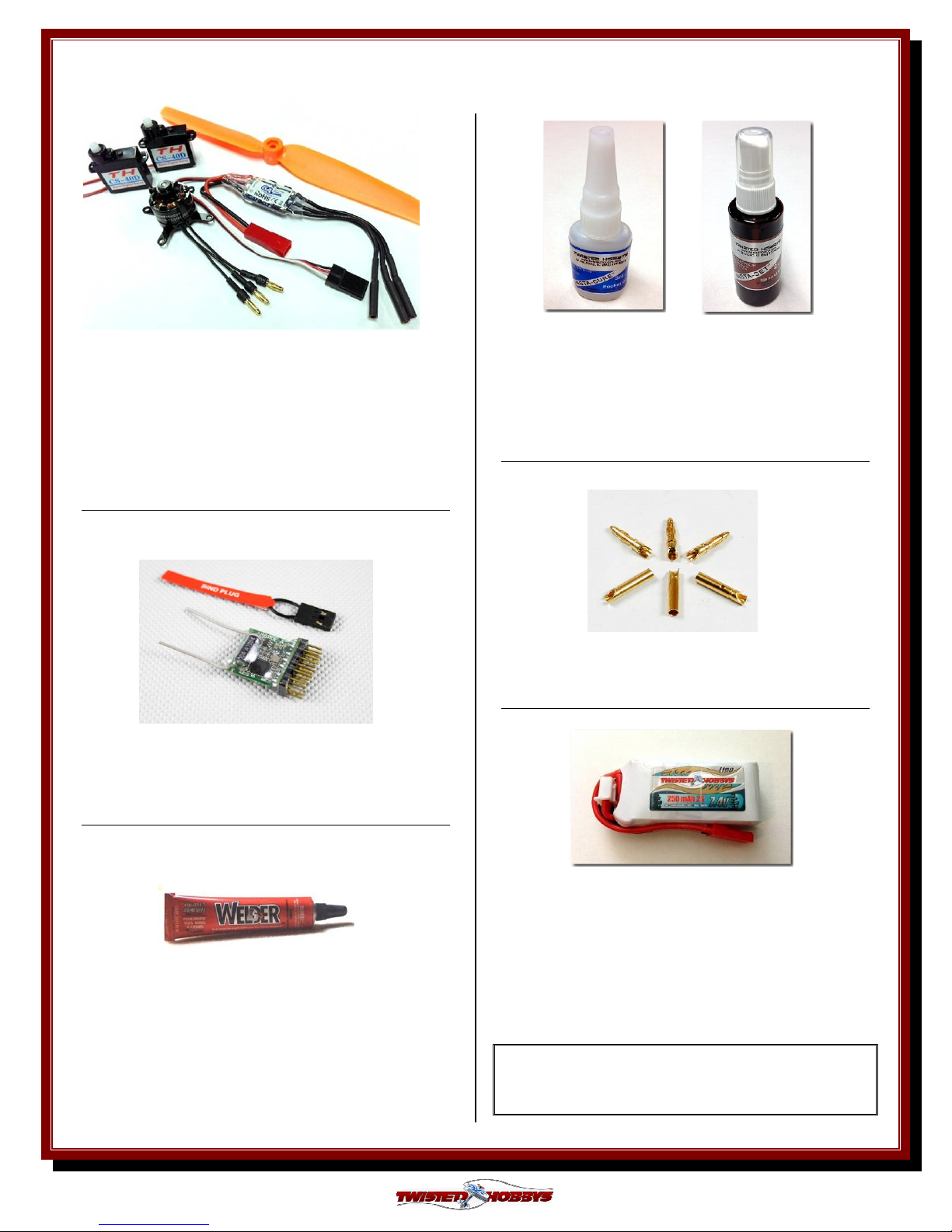
Power Combo Kit
(Matched by Twisted Hobbys)
1x
1x – 12g Crack Series 2650 kV motor
1x1x
1111xxxx – Twisted Hobbys 6A ESC w/dbl bec chip
1x
1x – 4.6g Digital Ball Bearing Nano servo
1x1x
1x
1x – prop 6x3
1x1x
Micro
Micro Receiver
MicroMicro
Minimum of 4 channels required
Perfect choice for building and repairing your
Twisted Hobbys EPP planes! This is the only
adhesive you will ever need. Welder virtually bonds
anything to anything! Clear, heavy-duty, flexible
and water-proof when dry. Use indoors or out. (1) 1
oz tube
Receiver
Receiver Receiver
CA and Kicker
Various thickness CA glues and
Activator available from Twisted
Hobbys’
Bullet Con
Bullet Connnnnectors
Bullet ConBullet Con
2mm gold plated / 3 pair
2s
2s Lipo
Lipo Battery
2s 2s
Lipo Lipo
180 or 250 mAh / 25-50C
Note: many of these “optional parts” shown or
similar items, may be available from the
Twisted Hobbys’ web store.
ectors
ectorsectors
Battery
BatteryBattery
Rev: 2013.02.02.v001b
6
Page 7
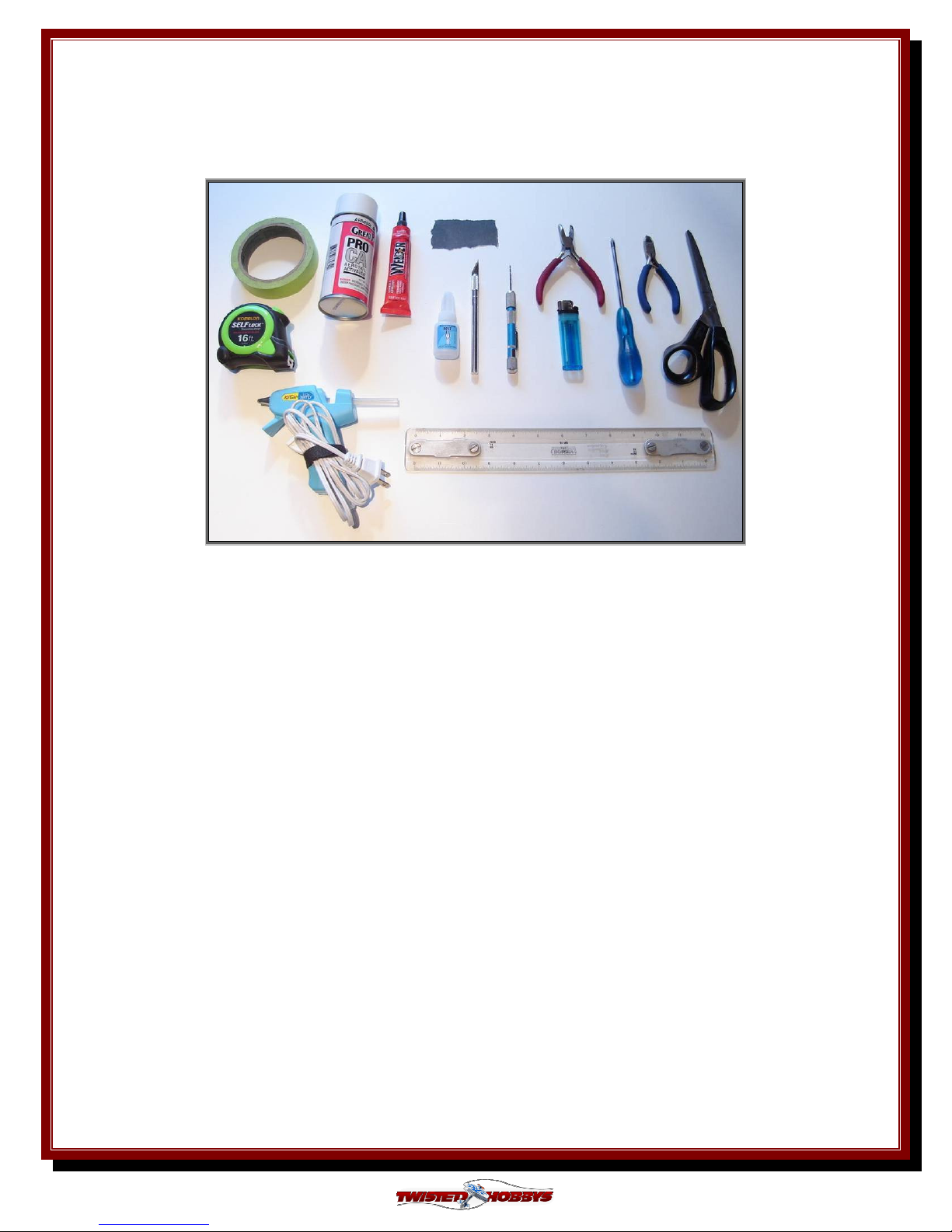
Tools
Tools &
Tools Tools
& Adhesives Needed
Adhesives Needed
&&
Adhesives Needed Adhesives Needed
• Tape Measure and
Tape Measure and Ruler
Tape Measure and Tape Measure and
• Lighter
Lighter
LighterLighter
• Small drill bits
Small drill bits
Small drill bitsSmall drill bits
• Welders
Welders Glue
Welders Welders
• Hobby Knife w/new Blad
Hobby Knife w/new Bladeeee
Hobby Knife w/new BladHobby Knife w/new Blad
• Needle Nose Pliers
Needle Nose Pliers
Needle Nose PliersNeedle Nose Pliers
• Wire Cutters
Wire Cutters
Wire CuttersWire Cutters
• Low Temp Hot Glue Gun
Low Temp Hot Glue Gun
Low Temp Hot Glue GunLow Temp Hot Glue Gun
• Course Sand Paper
Course Sand Paper
Course Sand PaperCourse Sand Paper
• Scissors
Scissors
ScissorsScissors
• SSSSmall Phillips Screw Driver
mall Phillips Screw Driver
mall Phillips Screw Drivermall Phillips Screw Driver
• CA
CA and Activator
and Activator
CACA
and Activator and Activator
Glue
GlueGlue
Ruler
RulerRuler
Rev: 2013.02.02.v001b
• Approx 18” string/thread
Approx 18” string/thread
Approx 18” string/threadApprox 18” string/thread
7
Page 8
THE BUILD
THE BUILD
THE BUILDTHE BUILD
CONSTRUCTION METHODS:
Building surface should be at least 2ft x 4ft and flat. Weights or some small heavy objects will be
handy for holding things in place during the time glue is setting.
Welders glue is used exclusively for this build, except for the control rod ends, which are glued
with thin CA. When usin
approx
approx five
approx approx
so locate carefully when bringing the two pieces together. If alignment is necessary while gluing
the two pieces together, do not allow the glue to tack up, simple apply and join immediately, you
will have several minutes to locate the two parts before the glue sets up. In most cases the parts
being glued can be handled with care in 30 minutes, full cure is approx 24 hours.
five minute
fivefive
When using the Welders glue, apply
When usinWhen usin
minutessss and then assemble
minute minute
g the Welders glue, apply a thin film to each surface
g the Welders glue, apply g the Welders glue, apply
and then assemble.... Note that this method will create a nearly instant bond,
and then assemble and then assemble
a thin film to each surface, allow to sit for
a thin film to each surfacea thin film to each surface
, allow to sit for
, allow to sit for , allow to sit for
STEP 1
STEP 1
STEP 1STEP 1
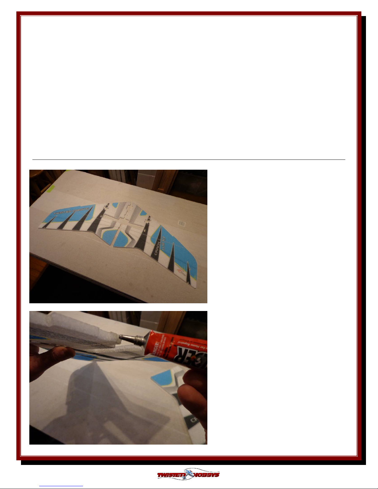
On a flat building surface (covered with
Parchment or Wax paper) locate the
two wing halves and test fit them
together. When assembling you want
the cut outs for the spars to line up
with each other.
Apply a thin layer of Welders to the
contact area of both wing halves, allow
to tack up for approx 10 minutes.
Rev: 2013.02.02.v001b
8
Page 9
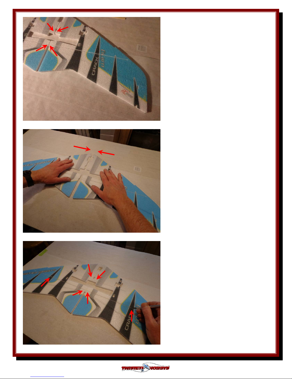
Carefully align the spar slots.
While maintaining alignment, bring
the two halves together and press
firmly.
STEP 2
STEP 2
STEP 2STEP 2
Remove the support tabs from the spar
slots.
Rev: 2013.02.02.v001b
9
Page 10
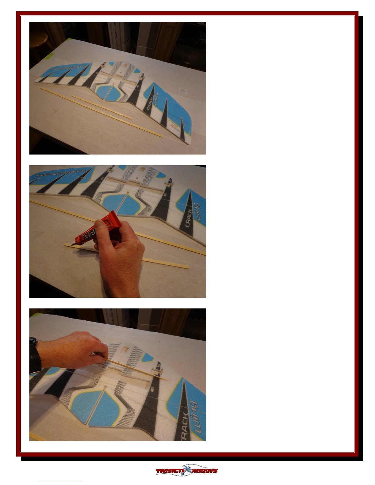
Locate the wing spars, check their fit
into the slots.
Coat both sides of the short spar with
a bead of Welders.
Insert the spar into the forward slot,
spreading it a little as you go to help
the glue get all the way in.
Rev: 2013.02.02.v001b
10
Page 11
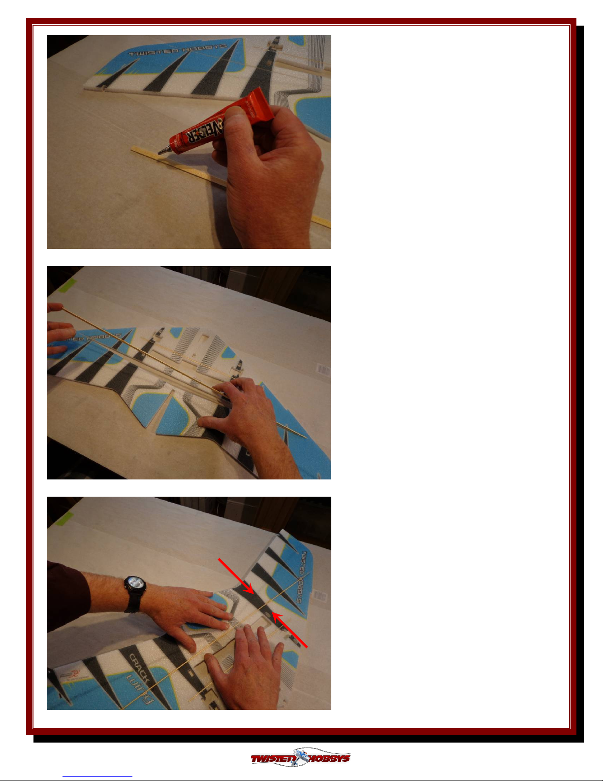
Coat both sides of the long spar with a
bead of Welders.
Insert the spar into the rearward slot,
spreading it a little as you go to help
the glue get all the way in.
Press the foam against the spar to
secure the bond.
Rev: 2013.02.02.v001b
11
Page 12
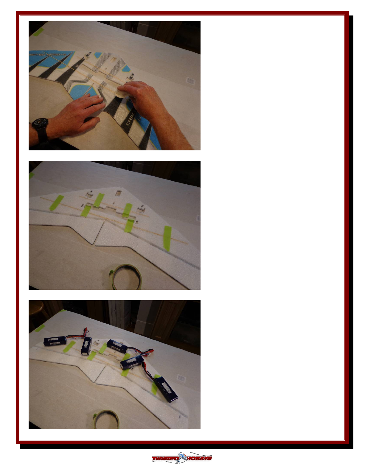
Wipe off any extra glue from both sides
Use some tape (high tack tape shown)
or other means to maintain pressure on
the glue joint while it cures
Add some weights to hold everything
flat while the glue dries.
Rev: 2013.02.02.v001b
12
Page 13
STEP 3
STEP 3
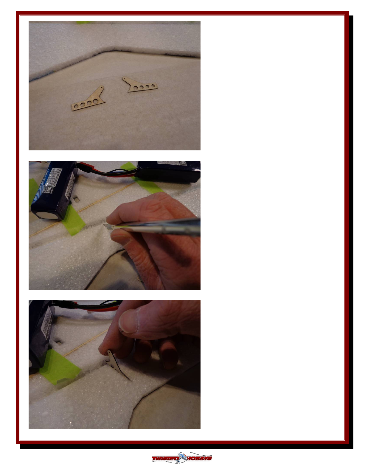
STEP 3STEP 3
Locate the wood control horns.
Complete the pre-made slot in the
Elevon so that it extends all the way
through
Test fit the horn.
Rev: 2013.02.02.v001b
13
Page 14

Coat both sides of the horn with
Welders.
Lay a small bead of Welders into the
slot.
Install the horn into the Elevon, make
special note to line up the profile of the
horn with the profile of the hinge slot
as shown.
Rev: 2013.02.02.v001b
14
Page 15

Wipe off any excess glue.
Repeat for the other Elevon.
Let everything dry. Apply weights to
help keep things flat.
STEP 4
STEP 4
STEP 4STEP 4
Locate the items shown.
Rev: 2013.02.02.v001b
15
Page 16

Slide the z-bend and shrink tubing
onto one of the carbon push rods
Heat shrink the very end only.
Apply a few drops of CA down the
open end of the heat shrink tubing.
Rev: 2013.02.02.v001b
16
Page 17

Shrink the tube completely. Apply
heat carefully and blot away any CA
that is forced out, onto a paper towel.
If the glue catches fire remove the
lighter and blow out.
Repeat for the other control rod.
PREPARE THE ELECTRONICS
PREPARE THE ELECTRONICS
PREPARE THE ELECTRONICSPREPARE THE ELECTRONICS
If your motor did not come with 2mm
bullets,, add them now. Also note that
your power combo may have come with
your power combo may have come with
your power combo may have come with your power combo may have come with
a different motor, same instructions
a different motor, same instructions
a different motor, same instructions a different motor, same instructions
apply
apply....
applyapply
Also note that
Also note that Also note that
As an option
As an option: you can solder the motor
As an optionAs an option
leads directly to the ESC. If choosing
this option, female plugs from the ESC
would be removed and wire insulation
stripped back. Solder and protect with
a single piece of heat shrink tubing on
each wire
Solder them on and prepare 3 small
pieces of shrink tubing
Rev: 2013.02.02.v001b
17
Page 18

Shrink the tubing.
Motor ready to connect to the ESC
Set up a new program on your Radio,
in this case the model has been named
“Cwing02”
Rev: 2013.02.02.v001b
18
Page 19

Go to your System Setup Page.
Go to the menu for Wing Type
selection.
Pick “Elevon” for the Wing Type
Rev: 2013.02.02.v001b
19
Page 20

Bind your Radio to the Receiver,
center all trims, set up the proper
direction and controls for the Elevons,
set sub trims so servos arms are 90
degrees to the servo and determine
correct motor rotation.
NOTE: if you chose to solder your
motor wires to the ESC you can change
the motor direction via the transmitter
programming method.
Attach the quick link to the Servo
arms. For the arms included with the
Twisted Hobbys CS-40D, use one hole
in for mild control (shown) and outer
most hole for extreme control
On a piece of cardboard or other soft
surface push the pin onto the keeper.
NOTE: the concaved side is UP in
this picture.
Rev: 2013.02.02.v001b
20
Page 21

PREPARE SERVOS
PREPARE SERVOS
PREPARE SERVOSPREPARE SERVOS
Add thin (skim) layer of Welders to the
three sides of the Servos that come into
contact with the surfaces of the cutouts
in the wing.
NOTE: The method being described
will allow for removal of the servos yet
hold them tight otherwise.
Set the servos aside to allow the skim
coating of Welder to dry thoroughly,
you should allow a couple hours for
this, longer if possible.
Put a small bead of Welders on the
matching surfaces of the wing cutouts.
Rev: 2013.02.02.v001b
21
Page 22

Smooth the glue out to a thin coat and
allow to dry a couple hours, longer if
possible.
NOTE: Once the glue has dried, there
will still be a “sticky” surface between
the servos and wing cut out, hold them
securely in place, but still remove-able
if needed
STEP
STEP 5555
STEP STEP
Locate the lower fuselage doubler
Position it as shown. The back edge
but be flush with the cutout in the
wing. This edge forms one of the motor
mount surfaces, making it flush will
ensure a nice flat surface for the motor
mount to fasten to later.
Rev: 2013.02.02.v001b
22
Page 23

Trace the location of the doubler
Coat each surface with a thin coat of
Welders
Allow the glue to tack up.
Rev: 2013.02.02.v001b
23
Page 24

Bring the two piece together,
remembering to keep the back edges
flush.
Completed assembly.
If the glue on the servos and wing has
dried, you can now install them into
the wing cutouts. Servo horns should
be sticking out on the bottom side.
NOTE: Install these in the same
positions as when you did your initial
radio setup earlier in the build.
Rev: 2013.02.02.v001b
24
Page 25

Both Servos in position
Decide what batteries you will be
using.
Mark as required for the foam that
needs to be removed.
Rev: 2013.02.02.v001b
25
Page 26

Remove the material as marked and
test fit the battery
STEP 6
STEP 6
STEP 6STEP 6
Locate the upper and lower center ribs.
Test fit the upper rib, making sure
that the back edge lines up with the
cut out in the wing.
Rev: 2013.02.02.v001b
26
Page 27

Test fit the lower rear rib.
NOTE: This part is NOT symmetrical
make sure it is orientation is such that
the back edge lines up with the cut out
in the wing.
Glue all the pieces together (wet) and
secure with pins or tap. Allow to dry.
Locate the motor mount
Rev: 2013.02.02.v001b
27
Page 28

With the edge of a file or coarse sand
paper, rough up one side of the motor
mount
Roughed up and ready for glue.
Coat the roughed up side with Welders,
and allow to tack up
Rev: 2013.02.02.v001b
28
Page 29

Coat the mating surface for the motor
mount on the fuselage with Welders,
and allow to tack up.
Once the glue has tacked up, assemble
the two pieces.
Motor mount installed and ready for
the motor to be installed.
Rev: 2013.02.02.v001b
29
Page 30

STEP 7
STEP 7
STEP 7STEP 7
Locate the push rods that were
assembled with ends earlier
Install the z-bend end into the Elevon
Horn.
With the Elevon in it’s neutral
position, rough cut the push rod to
approx. ¼ inch beyond the quick link.
Rev: 2013.02.02.v001b
30
Page 31

Push back the Elevon and slide the cut
end of the push rod thru the quick
link. It may be necessary to cut the
rod a little shorter.
Lightly tighten the set screw.
NOTE: Over tightening will crush the
carbon rod and ruin your push rod.
Repeat for the other side.
Rev: 2013.02.02.v001b
31
Page 32

Mount the motor… situate so the
cables come out in the area where you
want to install the ESC.
Note: motor shown may be different
Note: motor shown may be different
Note: motor shown may be different Note: motor shown may be different
than the one included in your power
than the one included in your power
than the one included in your power than the one included in your power
combo.
combo.
combo.combo.
Slit the Side Force Generators in prep
for assembly to the Elevon.
Do the same for both Rudders. Slit in
two places
Rev: 2013.02.02.v001b
32
Page 33

Test fit noting that the larger surface
area is the top of the rudder.
Lay down a bead of Welders on both
sides of the wing in the area that comes
into contact with the rudder. Avoid the
area directly around the servo, this will
make it easier to remove should it fail.
Spread the rudder and slide onto the
wing from the back side. Align with
the tabs and press together. Make sure
that the rudder is 90 degrees to the
wing. The glue will tack pretty quickly,
but until it does make there are no
gaps.
Rev: 2013.02.02.v001b
33
Page 34

The glue will tack pretty quickly, but
until it does, make there are no gaps.
Repeat the process for the SFG’s.
Test fit.
Rev: 2013.02.02.v001b
34
Page 35

Apply a small bead of Welders in the
are the SFG will contact.
Install the SFG and check for
squareness.
Repeat for the other side.
Make note of where the Center of
Gravity should be located.
Rev: 2013.02.02.v001b
C.G. = 13mm
C.G. = 13mm
C.G. = 13mmC.G. = 13mm
ba
back from front spar
ck from front spar
baba
ck from front sparck from front spar
35
Page 36

Since the battery is in a fixed position
on this plane, you will need to balance
by locating the ESC and Receiver
appropriately.
Move the components around until the
plane balances 13mm back from the
front spar.
Note: CG range on Flying wings is
much narrower that on conventional
planes, take your time and get this as
close as you can to the recommended
spot.
If using all the Twisted Hobbys’ stuff,
and the 250mAh Twisted Hobbys’
LiPo battery, your ESC and Receiver
should be located approx as shown in
regards to the front to back position.
Placement from side to side is not as
critical, but you should keep lateral
balance in mind. You could also
mount all you gear on the bottom side
if desired.
Rev: 2013.02.02.v001b
36
Page 37

Bottom side. For this build we chose
to keep all the electronics on the top in
order to keep them save during
landings.
…………….. READY SET GO!
ENJOY!
Rev: 2013.02.02.v001b
37
Page 38

Center of Gravity
Center of Gravity
Center of GravityCenter of Gravity
13
13mm back from
mm back from Forward Spar
1313
mm back frommm back from
Locate the electronics to establish the proper Center of Gravity.
CG point is 13mm back from the Forward Spar. For flying wings it is important
for the location of the CG to be very accurate the acceptable range is very narrow.
Forward Spar
Forward SparForward Spar
Rev: 2013.02.02.v001b
38
Page 39

Control Throws
Control Throws
Control ThrowsControl Throws
3D / Combat Flight
Max Allowed as determined by Rudder Cut-Outs – SEE PICTURES BELOW
60 to 75% expo
Sport
20 degrees all surfaces
30 to 45% expo
Depending on your Radio the Elevon mix / setting may “overdrive” the controls surfaces.
It is very important to determine the max travel while the transmitter sticks are in
the extreme corners of the Gimble. Individual Elevator and individual Aileron control
will not be close to the limits at all, so do not set the max travel for the individual channels
in this manner. Failure to set the limits as a COMBINED CONTROL could result in
damage to the servos.
:
:
As shown above “Full Up” does not reach the limits
As shown above “Full Up” does not reach the limits
As shown above “Full Up” does not reach the limits As shown above “Full Up” does not reach the limits
established by the cut out in the rudder fin. However in
established by the cut out in the rudder fin. However in
established by the cut out in the rudder fin. However in established by the cut out in the rudder fin. However in
the “Full Up
the “Full Up &&&& Left” situation the
the “Full Up the “Full Up
bottom out at the position of the cut out. C
bottom out at the position of the cut out. Care must be
bottom out at the position of the cut out. Cbottom out at the position of the cut out. C
taken when
taken when programming
taken when taken when
you are unsure of the travel loosen the screw in the quick
you are unsure of the travel loosen the screw in the quick
you are unsure of the travel loosen the screw in the quick you are unsure of the travel loosen the screw in the quick
link and experiment with your radios
link and experiment with your radios programming
link and experiment with your radios link and experiment with your radios
you are satisfied that it will not overdrive the control
you are satisfied that it will not overdrive the control
you are satisfied that it will not overdrive the control you are satisfied that it will not overdrive the control
surface.
surface.
surface.surface.
FULL UP
FULL UP
FULL UP FULL UP
programming as to not overdrive the servos. If
programmingprogramming
FULL UP
Left” situation the Elevon
Left” situation the Left” situation the
as to not overdrive the servos. If
as to not overdrive the servos. If as to not overdrive the servos. If
FULL UP &&&& LEFT
FULL UP FULL UP
Elevon is set to just
ElevonElevon
programming until
programmingprogramming
is set to just
is set to just is set to just
are must be
are must be are must be
LEFT
LEFT LEFT
until
until until
Rev: 2013.02.02.v001b
39
Page 40

PRE
PRE----FLIGHT
PREPRE
FLIGHT &
FLIGHT FLIGHT
& testing
testing
&&
testing testing
Preflight Checks
Motor
positions, and transition smoothly from
low to high RPM. If the motor is turning
backwards, reverse two of the three wires
between the motor and ESC. Check that
the screws holding the motor to the
airframe are tight and secure.
Flight Controls
sticks in the neutral positions. Ensure that
all controls and linkages move freely.
Double check that all hinged areas are free
from rips or tears. Verify proper control
surface directions. Right Roll is – right
aileron up, left aileron down, Left Roll is
left aileron up and right aileron down.
Batteries
to each flight. Watch transmitter battery
level and follow manufactures
recommendations. Motor battery should
not be drained any further than
recommended by the manufacture, use a
timer to prevent an over discharged
condition.
Radio
and throttle in the low position. Check
that rate switches and mixes are set
properly.
Range Check
motor running per radio manufactures
instructions. If there is insufficient range
or significant reduction with the motor
running, resolve and re-test before flying.
: Should run smoothly at all stick
: Should be centered with
: Should be fully charged prior
:::: All trims should be set to neutral
:::: With and without the
The first flights should be done with the
CG at the recommended position, and
reduced control rates until comfortable
with your handling of the aircraft. As your
experience with the aircraft grows
experiment with different CG points and
control rates. After all flights, check the
aircraft over for damage and/or other items
that may adversely affect flight
performance.
This Wing is a 3D capable EPP plane and
will take anything you throw at it,
including the occasional crash. If, as the
result of a crash, the foam tears, simple
glue with Welders or CA. Many pilots
prefer Welders because it remains flexible
after drying. CA however, is more suited
for the “quick” repair.
This aircraft can be flown indoors or
outdoors. It is the perfect size for a
friendly game of combat at the neighbor
park or smaller flying field, allowing for
plenty of opportunity to shoot your foe
down. It is also great stand alone plane for
simple fun and R/C pleasure.
This EPP plane should be stored on its
fins in the Vertical Take-off position,
doing otherwise could cause the airframe to
twist. Storage in a hot car could also cause
damage.
Flight Testing
Storage
Be safe and enjoy, thank you again for purchasing a Twisted Hobbys’ Product!
Rev: 2013.02.02.v001b
40
Page 41

NOTES
NOTES &
NOTESNOTES
& s/u Sheet
s/u Sheet
&&
s/u Sheet s/u Sheet
Rev: 2013.02.02.v001b
41
Page 42

TIPS AND TRICKS
TIPS AND TRICKS
TIPS AND TRICKSTIPS AND TRICKS
- A good building surface is “drop ceiling” panel from a local hardware store on a nice flat board
- use parchment paper between the areas being glued and your work surface
- heavy flat objects (like books, batteries, etc.) could be used to hold everything flat
- When resetting your radio, start with all the ATV’s or throw volumes at 100%.
- Make sure you have set the direction of the servos correctly before attempting to trim for zero position.
- If possible try the servo horns in different locations to determine which position will require the least
amount of sub trim.
- Installing the servo horns in their final location and attaching quick links to the servos may make
servo installation much easier later.
- On the Orange Rx, the negative pin is the one closest to the flat side of the circuit board.
- Keep a good supply of sharp knife blades handy when building a foamie airplane.
- Use low temp hot glue for gluing electronics, this will allow for easy removal later if necessary. The
low temp hot glue can be “released” by “painting” the glue bead with an alcohol soaked cotton swab a
couple times.
- A business card with the corners clipped off can be used as a small square.
- Allowing the Welders glue to set for five minutes before assembly will shorten the tack up time, just
be sure if doing it this way that you get the parts into position quickly, as the glue will start to bond
on contact. Any joints that you feel are going to require adjustment, it is best to assembly the pieces
while the glue is wet.
- The Green (high tack) masking tape works the best when used to clamp things together on an EPP
foam airplane.
- When gluing the rudder to the fuselage, stick pins could be used to hold in position if wanting to
handle the airframe before it is completely dry
- A rotary tool with a cutting wheel could be used to produce grooves in fiber glass parts instead of
coarse sand paper. Use a hatch pattern. This creates more bonding area for the glue.
Rev: 2013.02.02.v001b
42
 Loading...