

Page 1

32” AIRFRAME ASSEMBLY MANUAL
EXTRA SLICK
Crack yak-55
EDGE 540
Sbach 342
Specifications
Wing span – 32” / length – 31” / A UW 6-1/8oz
50w motor / 10-12 amp ESC / 4 ch radio
Twisted Hobbys
www.twistedhobbys.com
Rev: 2012.04.23a 1
Page 2

TABLE OF CONTENTS
Page
WARNING INFORMATION............................................................................................................................................3
SHIPPING DAMAGE........................................................................................................................................................ 3
OUR MISSION .................................................................................................................................................................. 3
SAFETY NOTES ...............................................................................................................................................................4
IMPORTANT: PRIOR TO ANY ASSEMBLY.........................................................................................................4
KIT CONTENTS ...............................................................................................................................................................5
OPTIONAL PARTS........................................................................................................................................................... 6
TOOLS & ADHESIVES NEEDED ...................................................................................................................................7
ASSEMBLY ....................................................................................................................................................................... 8
W
ING / NOSE / ELEVATOR
E
LEVATOR SERVO - (5G
A
ILERON SERVO – (9G
F
USELAGE TRUSS
A
ILERON SERVO HORN ASSEMBLY
B
UILDING AILERON CONTROL RODS
A
ILERON CONTROL HORNS
U
PPER FUSELAGE AND RUDDER
R
UDDER & ELEVATOR CONTROL HORNS
P
USH ROD GUIDES
E
LEVATOR & RUDDER PUSH RODS
I
NSTALLING AILERON PUSH RODS
M
OTOR MOUNT
S
IDE FORCE GENERATORS
R
ECEIVER &
........................................................................................................................................................... 10
.............................................................................................................................................................17
ESC........................................................................................................................................................... 18
.................................................................................................................................................8
)................................................................................................................................................... 9
).....................................................................................................................................................9
................................................................................................................................. 11
...............................................................................................................................12
............................................................................................................................................. 12
...................................................................................................................................... 13
.........................................................................................................................14
......................................................................................................................................................... 14
................................................................................................................................. 15
.................................................................................................................................. 16
.............................................................................................................................................. 17
SETUP.............................................................................................................................................................................. 18
C
ONTROL SURFACE CENTERING
C
ENTER OF GRAVITY
C
ONTROL THROWS
3D Flight .................................................................................................................................................................. 18
Sport......................................................................................................................................................................... 18
PRE-FLIGHT & TESTING............................................................................................................................................. 19
P
REFLIGHT CHECKS
Motor........................................................................................................................................................................ 19
Flight Controls.......................................................................................................................................................... 19
Batteries ................................................................................................................................................................... 19
Radio........................................................................................................................................................................19
Range Check............................................................................................................................................................. 19
F
LIGHT TESTING
S
TORAGE
NOTES ............................................................................................................................................................................. 20
SET UP DATA ................................................................................................................................................................. 20
....................................................................................................................................................................... 19
...................................................................................................................................................... 18
......................................................................................................................................................... 18
........................................................................................................................................................19
.............................................................................................................................................................19
.....................................................................................................................................18
Rev: 2012.04.23a 2
Page 3

TWISTED HOBBYS
Website: www.twistedhobbys.com – email: sales@twistedhobbys.com
Thank you for your purchasing a Twisted Hobbys’ 32” Model. Please read through the entire manual before
beginning to build this model. If you have any questions please contact us at the above indicated email address.
WARNING INFORMATION
WARNING INFORMATION
WARNING INFORMATIONWARNING INFORMATION
This R/C Aircraft is not a toy! Read and understand the entire manual before assembly. If misused, it can
cause serious bodily harm and property damage. Fly only in open areas, and AMA (
Aeronautics
by other manufactures’ products. If you are not an experienced pilot and airplane modeler you must use the
help of an experienced pilot or an authorized flight instructor for the building and flying of this model aircraft.
These instructions are suggestions only on how to assemble this model. There are other ways and methods to
do so. Twisted Hobbys has no control over the final assembly, the materials and accessories used when
assembling this kit, or the manner in which the assembled model, installed radio gear and electronic parts are
used and maintained. Thus, no liability is assumed or accepted for any damage resulting from the use of the
assembled model aircraft or from this instruction manual including but not limited to direct, indirect,
incidental, special, and consequential damages. By the act of using this user-assembled product, the user
accepts all resulting liability. In no event shall Twisted Hobbys’ liability exceed the original purchase price of
the kit.
) approved flying sites. Do not over look the warnings and instructions enclosed or those provided
Academy of Model
SHIPPING DAMAGE
SHIPPING DAMAGE
SHIPPING DAMAGESHIPPING DAMAGE
Twisted Hobbys checks each plane before shipping to ensure that each kit is in fine condition. We have no
bearing on the condition of any component parts damaged by use, modification, or assembly of the model.
Inspect the components of this kit upon receipt. If you find any parts damaged or missing, contact Twisted
Hobbys immediately. We will not accept the return or replacement of parts on which assembly work has already
begun. Twisted Hobbys reserves the right to change this warranty at anytime without notice.
OUR MISSION
OUR MISSION
To provide the best products and service to our customers at the lowest prices possible.
We take great pride in our company, our commitment to customer service and in the
products we sell. Our online store is designed to provide you with a safe and secure
environment to browse our product catalog.
OUR MISSIONOUR MISSION
Thank you for shopping with Twisted Hobbys!
Thank you for shopping with Twisted Hobbys!
Thank you for shopping with Twisted Hobbys!Thank you for shopping with Twisted Hobbys!
Rev: 2012.04.23a 3
Page 4

SAFETY NOTES
SAFETY NOTES
SAFETY NOTESSAFETY NOTES
Before assembling and flying this model, read carefully any
instructions and warnings of other manufacturers for all the
products you installed or used on your model, especially radio
equipment and power source.
Check thoroughly before ever flight that the airplanes’
components are in good shape and functioning properly. If you
find a fault do not fly the model until you have corrected the
problem.
Radio interference caused by unknown sources can occur at any
time without notice. In such a case, your model will be
uncontrollable and completely unpredictable. Make sure to
perform a range check before every flight. If you detect a control
problem or interference during a flight, immediately land the
model to prevent a potential accident.
Youngsters should only be allowed to assemble and fly these
models under the instruction and supervision of an experienced
adult.
Do not operate this model in a confined area.
Do not stand in line with, or in front of a spinning propeller and
never touch it with any object.
IMPORTANT: PRIOR TO ANY ASSEMBLY
Please Note: after removing kit from shipping box, lay
each piece flan on a hard surface, this will allow the
airframe to straighten out if lightly bend from
shipping. Do not worry since EPP is very pliable and
can be bend back if bend out so shape easily.
Rev: 2012.04.23a 4
Page 5

kit contents
kit contents
kit contentskit contents
shape and contents will vary slightly depending on the airframe purchased
EDGE 540 EPP
EDGE 540 EPP
EDGE 540 EPPEDGE 540 EPP
standard parts list:
1x - left & right wings w/attached ailerons
1x - main fuselage w/attached rudder
1x - elevator w/attached control surface
1x - horizontal nose section
1x – horizontal fuselage section
2x – side stiffener strips (trusses)
2x – side force generators
1x - wood main spare
2x – aileron control rods
1x – elevator control rod
1x – rudder control rod
1x – hardware packet
1x – instruction sheet
(shown)
Hardware packet detail
Rev: 2012.04.23a 5
Page 6
OPTIONAL PARTS
OPTIONAL PARTS
OPTIONAL PARTSOPTIONAL PARTS
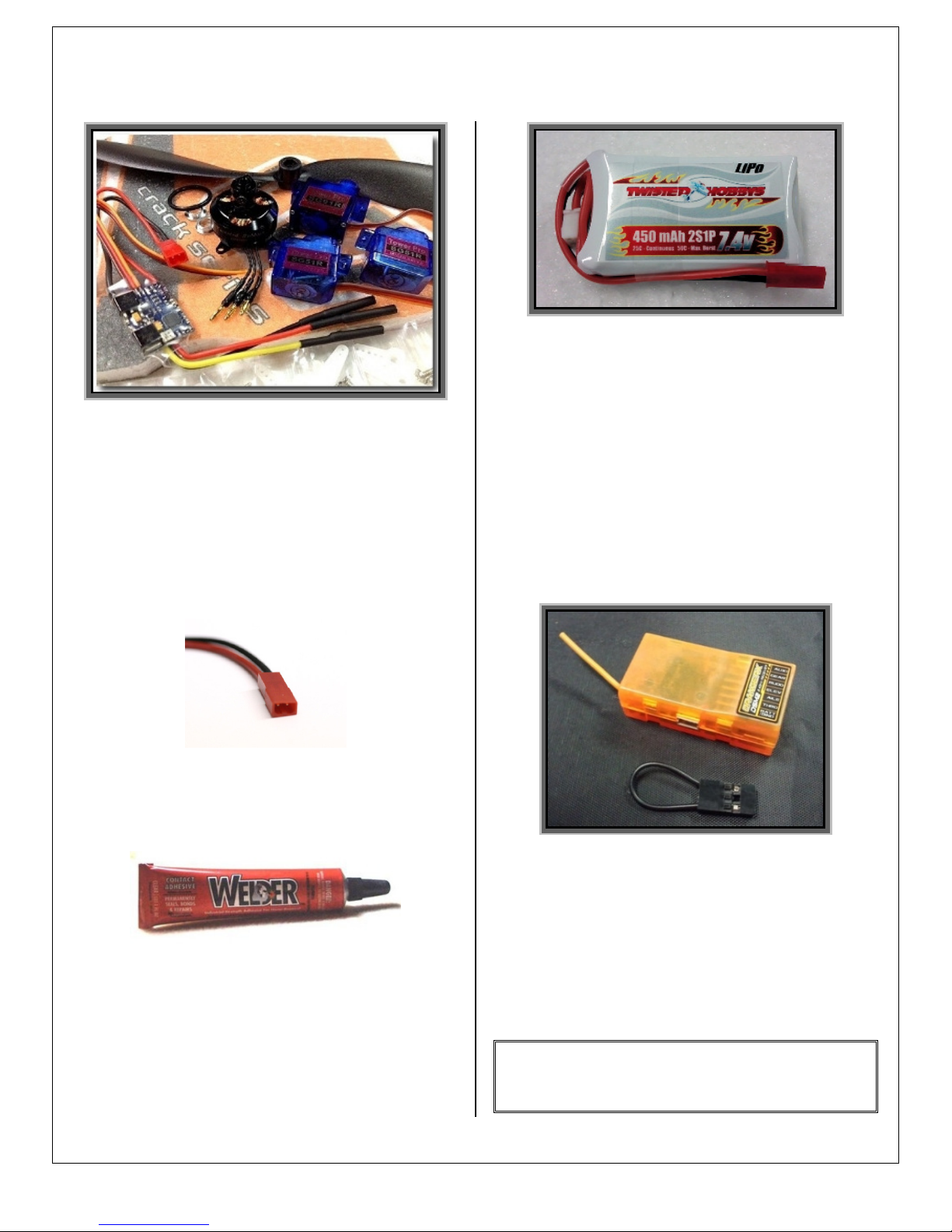
Power Combo Kit
(Matched by Twisted Hobbys)
1x
1x – 1450-1800kv Outrunner Brushless Motor
1x1x
1x
1x – ESC 10A-12A ESC
1x1x
1x
1x – 9g Micro Servo
1x1x
2x
2x – 5g Micro Servo
2x2x
1x
1x – Slow Fly Prop (8x4.3 - 9x4.7)
1x1x
includes:
Twisted Hobbys
450mah Battery w/connector
Voltage: 2S1P / 2 Cell / 7.4V
Discharge: 25C Constant / 50C Burst
Weight: 30g (including wire, plug & case)
Dimensions: 65x29x11mm
Balance Plug: JST-XH
Discharge Plug: mm Connector
specs:
Capacity: 450mAh
JST Female Connector
used for ESC to Battery connection
Perfect choice for building and repairing
your Twisted Hobbys EPP planes! This is
the only adhesive you will ever need.
Welder virtually bonds anything to
anything! Clear, heavy-duty, flexible and
water-proof when dry. Use indoors or out.
(1) 1 oz tube
Micro
Micro R
MicroMicro
Max Recommended Weight: 9.8g
Minimum of 4 channels required
Note: many of these “optional parts” shown or
similar items, may be available from the
Twisted Hobbys’ webstore.
Receiver
eceiver
R R
eceivereceiver
Rev: 2012.04.23a 6
Page 7

Tools
Tools &
Tools Tools
& Adhesives Needed
Adhesives Needed
&&
Adhesives Needed Adhesives Needed
• Ruler
Ruler
RulerRuler
• Course Sand Paper
Course Sand Paper
Course Sand PaperCourse Sand Paper
• Scissors
Scissors
ScissorsScissors
• NNNNeedle Nose Pliers
eedle Nose Pliers
eedle Nose Plierseedle Nose Pliers
• Wire Cutters
Wire Cutters
Wire CuttersWire Cutters
• Small Phillips Screw Driver
Small Phillips Screw Driver
Small Phillips Screw DriverSmall Phillips Screw Driver
• Hobby Knife
Hobby Knife
Hobby KnifeHobby Knife
• Lighter
Lighter
LighterLighter
• Stick Pins
Stick Pins
Stick PinsStick Pins
• Solder Iron
Solder Iron & Solder
Solder IronSolder Iron
• Welders
Welders or Hot Glue
Welders Welders
• Foam Safe
Foam Safe CA
Foam Safe Foam Safe
& Solder
& Solder & Solder
or Hot Glue
or Hot Glueor Hot Glue
CA –––– thin or medium
CA CA
thin or medium
thin or medium thin or medium
Rev: 2012.04.23a 7
• CA Kicker
CA Kicker (optional)
CA KickerCA Kicker
(optional)
(optional) (optional)
Page 8

Assembly
Assembly
AssemblyAssembly
Note: The pictures in this assembly manual are
of the Edge 540. Construction for the all of the
32” airframes is very similar and can be built
with this manual.
Wing / Nose / Elevator
Glue the left and right wings, fuselage
center section, nose piece and elevator
together. Start by laying all needed parts
on a flat table, test fit, noticing the
different size tabs before gluing
Keep the slot in the main wing clear of
glue and open, so that it can accept the
main spare
Glue each part together than apply a few
weights on the top of each to ensure each is
sitting flat and connected while drying.
Right after gluing, make sure the wings are
square to the fuselage center section and
measure from the tips of the elevator to the
tips of the wing, and make equal. This will
ensure proper orientation between wing
and elevator
Coat both sides of the spar with Welders
glue. Spread the foam and lay in the spar.
Use tape weight or stick pins to make sure
the joint is held firm until dry
Rev: 2012.04.23a 8
Page 9

Note:
Note: before installing any radio gear and
Note:Note:
or electronics hook everything up and test
for proper function. Also at this time note
the center locations of all servos and attach
the quick links to the horns as shown.
Determine which servos will be used for
the Elevator and Rudder and attach the
horns accordingly, doing this now is less
tedious than doing it after the servos are
glued in.
Elevator Servo - (5g)
Glue with Welders or Hot Glue
Aileron Servo – (9g)
With the nose of the aircraft hanging off
the work surface, locate the aileron servo in
position as shown. Cut/remove the lower
fuselage clearance slots for both the aileron
and elevator servos as shown below
With the bottom of the plane facing up,
locate the Elevator Servo as shown. Trace
around the servo and remove the necessary
foam for it to fit snuggly in position. If you have
chosen to install the servo horns, gently move
the arm so that it is parallel to the servo, and
allows the servo to lay flat in the cutout
Insert and glue aileron servo into place,
make sure the servo tabs sit flush with the
bottom of the main wing. Now the lower
fuselage can be glued to the wing / elevator
assembly
Rev: 2012.04.23a 9
Page 10

Fuselage Truss
Locate the 2 fuselage truss strips. Note
that the parts are beveled to fit flush at 45
degrees when installed
Test fit the Truss members on the
underside of the airframe. They should be
centered roughly between the aileron servo
and the elevator control surface relief cut
out. Before gluing, notice that the flat
section is toward the elevator as shown. At
this time you could also consider how your
servo wires will be routed and situate them
under the trusses
Situated the nose of the aircraft beyond the
work surface to provide clearance for the aileron
servo and allow the airframe assembly to lay
flush on the work bench
Glue the truss strips to the fuselage. It will
be necessary to secure the strips in place
while the glue is drying. Stick pins or
small tacks of hot glue work will for this
Rev: 2012.04.23a 10
Note:
Note: make sure when securing the strips
Note:Note:
(with what ever method chosen) that the
lower vertical section of the fuselage and
the main horizontal wing and elevator
section remain square to each other.
Allow glue to dry completely before
Allow glue to dry completely before
Allow glue to dry completely before Allow glue to dry completely before
moving on to the next steps
moving on to the next steps....
moving on to the next stepsmoving on to the next steps
Page 11

Locate the wood differential
aileron horn and the stock 9g
servo horn. Drill the stock
horn out slightly smaller then
screws being used. If using the
screws that came with the 9g
servo, use a 1/16” diameter
drill bit
Drill the differential (wood)
horn out to provide clearance
for the screws being used. If
using the screws that came with
the servos, use a 3/32”
diameter drill bit
Check the alignment of the
holes in the differential horn
and the stock horn. If the holes
do not match it could case the
wood differential horn to split
Aileron Servo Horn Assembly
If desired, clip the extra length
off of the stock horn
Screw the two pieces together
Clip off the extra length of the
screw. A rotary tool with a
cutting wheel also works, but
use caution to not over heat the
screw and melt the plastic
Finished horn assembly ready
for installation onto the servo
output shaft
Install on to the servo output
shaft with the arms pointing
forward. It will be necessary
“push” the foam off to the side
a little in order to access the
output shaft screw location.
Note: make sure the servo is
Note: make sure the servo is
Note: make sure the servo is Note: make sure the servo is
centered electronically before
centered electronically before
centered electronically before centered electronically before
installing the horn
installing the horn
installing the horninstalling the horn
Installed and ready for linkages
Note:
Note: it is important for the
Note:Note:
differential horn to be installed
as shown in order to achieve
equal up and down aileron
control surface deflection
Rev: 2012.04.23a 11
Page 12

Building Aileron Control Rods
Assembly the z-bends wires onto one end
only of two short
1. Sand the end of the z-bend wire
that will be attached to the carbon
rod. Use rough sand paper
2. Lightly sand the end of the carbon
rod in the area where the wire zbend will be attached
3. Wipe/clean the sanded areas of
each part with a cloth dampened
with alcohol
4. Position the z-bend wires on the
ends of the rod. Before applying
the CA, the wires can be held in
place with a small alligator clip or
a couple small pieces of shrink
tubing slid into position and
shrunk to hold
5. Apply CA and hit with kicker
6. Slide a piece of shrink tubing long
enough to cover the wire and
shrink to fit
7. Repeat process the other short rod
Note: only one end of each rod needs to
have a z-bend wire attached to it
short carbon rods
shortshort
Aileron Control Horns
Locate the control horns that are etched
the with “1” and install the mini easy
control rod connector. Make a left and
right hand assembly
Install on the under side of the airframe,
with the easy connector towards the
outboard side of the wing. Coat with glue
and slide into place as shown. Locate fore
and aft by situating the hole with the easy
connector installed directly over the hinge
point of the aileron control surface
Installed Aileron Control Horns
Rev: 2012.04.23a 12
Page 13

Upper Fuselage and Rudder
Position the upper fuselage half so that you
can locate and mark the areas where foam
needs to be removed for the servos
Once satisfied with the fit, glue the top
fuselage half to the existing assembly.
Make sure and adjust if necessary for
squareness. Allow to dry.
Attach the Rudder Control surface and the
black foam Canopy as shown
Cut and test fit
Rev: 2012.04.23a 13
Page 14

Rudder & Elevator Control Horns
Note: In order to avoid the potential of
melting the EPP foam while installing the
Z-Bends as instructed later in this manual,
only fit
fit the horns at this time, and glue to
fitfit
control surface after
after the “z-bend – rod”
afterafter
assembly has been attached to the horn
Locate the Elevator Control Horn (marked
#2) and slide into the pre-cut slot
Push Rod Guides
Rudder Guides are installed on the left side of
the upper fuselage. Locate approx as shown,
use one of the long carbon rods to help located
the Guides in a straight line and for correct
rudder control horn position. A small slit in
the foam with a hobby knife and sanding a
slight “chisel” shape to the guide will make it
easier when poking the ends into the foam
Locate the horn so that the hole is directly
over the hinge line
Repeat for the Rudder Control Surface
with the other #2 horn
Elevator Guides are installed on the rightupper side of the fuselage horizontal deck.
Again, use one of the long carbon rods to
ensure a straight run and alignment with the
elevator control horn
Rev: 2012.04.23a 14
Page 15

Elevator & Rudder Push Rods
Slide the control rod through the rod
guides and the easy connector
Install a z-bend into the horn and slide a
piece of shrink tubing on the rod as shown
Finished assembly
Repeat for Rudder control rod
Glue with CA to the control rod. Be careful
so that no CA gets into the horn hole. Heat
shrink the tubing. use caution to avoid
damaging the foam if using this method of
install the z-bends on the control rods.
Shield the foam with a piece of foil or thin
metal if necessary
Alternate Method
Alternate Method
Alternate MethodAlternate Method
If you have chosen not glue the elevator
and rudder horns in, you can at this time
completely build the ends of these two
control rods on the bench and shrink the
ends with out worry of damaging the
aircraft. The rods can be slid through the
guides (and quick link) from the control
surface end of the plane. Once in position
remove the horn from the control surface,
insert the z-bend link through the control
horn hole, coat the horn with glue and
return it to the slot to dry
Rev: 2012.04.23a 15
Page 16

Trim as desired, leaving approx ¼” for
adjustments and strength
CAUTION
CAUTION
CAUTIONCAUTION
Do not over tighten the quick link screws,
they will cause damage to the carbon rods
if made too tight. To get a feel for how
tight to make them, experiment on part of
the extra length. Also if the ends of the
screws have any burrs or sharp edges,
carefully sanding these off will help to
prevent the screw from “digging” into the
carbon rod
Note
Note:::: there are many different techniques
NoteNote
for attaching the z-bend wires to carbon
rods. The important points are to make
sure the areas to be glued, have been
roughed up with sand paper and are
cleaned thoroughly before gluing. Equally
important is to make sure the CA does not
run into the control horn holes, if possible,
situate the airframe so that the glue tends
to run in the opposite direction
Installing Aileron Push Rods
Insert the z-bend end into the aileron
differential horn as shown
Slide the bare end through the easy
connector as shown. It may be necessary to
shorten the rod slightly so that while
deflecting the aileron control surface the
rod can slide through the easy connector
hole. Trim as desired, leaving approx ¼”
for adjustments and strength
Rev: 2012.04.23a 16
Page 17

Motor Mount
Prep the surface to be glued. Use medium
grit sand paper, clean with alcohol
Using Welders’ glue, evenly coat the
prepped side of the motor mount and the
mating area on the nose of the fuselage.
Let sit for 1 minute before attaching
Install the motor using the provided
hardware in such a way that the wires will
be on the same side as you have chosen to
mount the ESC. Prop is installed by
placing the propeller onto the shaft and
then looping the o-ring on one of the
screws, over the prop hub and onto the
other screw.
Side Force Generators
Slit along the cut-out as shown, coat with
Welders and position into the slots on the wing,
repeat for the other side
Press and hold in place for a minimum of
1 minute. Allow to dry
attaching motor
attaching motor....
attaching motorattaching motor
Allow to dry thoroughly before
Allow to dry Allow to dry
thoroughly before
thoroughly before thoroughly before
Rev: 2012.04.23a 17
Page 18

Receiver & ESC
ESC shown on the left underside. Either
side is acceptable if mounting the battery
as shown below. In general the ESC and
Receiver should be located on the opposite
side as the battery. Equalize the balance
from side to side in how you locate the
items
Servo wires and leads can be tucked in
behind the truss if desired
Center of Gravity
200mm back from
200mm back from
200mm back from 200mm back from
the Nose
the Nose
the Nosethe Nose
Locate the battery last, and use it to
establish the proper Center of Gravity.
Starting CG point is 200mm back from
the nose
the nose of the airplane, ie the surface the
the nosethe nose
motor mount is glued to. IIIIffff wanting to
experiment with
experiment with the CG point, do not
experiment with experiment with
locate the battery as shown
locate the battery as shown, attach with
locate the battery as shownlocate the battery as shown
Velcro so that it can be moved around
during the process of determining the
desired spot. CG may vary
starting with the battery above the wood
starting with the battery above the wood
starting with the battery above the wood starting with the battery above the wood
spar and
spar and adjust to your liking
spar andspar and
CG point is 200mm back from
CG point is 200mm back from CG point is 200mm back from
the CG point, do not
the CG point, do not the CG point, do not
CG may vary, we suggest
CG may varyCG may vary
adjust to your liking....
adjust to your liking adjust to your liking
wanting to
wanting to wanting to
, we suggest
, we suggest , we suggest
setup
setup
setupsetup
Control Surface Centering
It is important to note that control surface
centering will be effected by ambient
temperature. EPP foam will expand and
contract when the temperature changes,
which in turn will change the position of the
control surface. This is normal and NOT the
result of a faulty servo. If flying in fluctuating
temperatures, simple adjust the trim before
each flight.
Control Throws
3D Flight
60 to 75% expo
Sport
30 to 45% expo
For 3D flight, set all the control throw up
at 35 to 45 degrees. This airframe is very
equally balanced and designed to like
similar throw movements.
Experiment with Expo and Dual Rates to
suit your own flying style.
: 35 to 45 degrees all surfaces
: 20 to 30 degrees all surfaces
Rev: 2012.04.23a 18
Page 19

PRE
PRE----FLIGHT
PREPRE
FLIGHT & testing
FLIGHTFLIGHT
& testing
& testing & testing
Preflight Checks
Motor
positions, and transition smoothly from
low to high RPM. If the motor is turning
backwards, reverse two of the three wires
between the motor and ESC. Check that
the screws holding the motor to the
airframe are tight and secure.
Flight Controls
sticks in the neutral positions. Ensure that
all controls and linkages move freely.
Double check that all hinged areas are free
from rips or tears. Verify proper control
surface directions. Right Roll is – right
aileron up, left aileron down, Left Roll is
left aileron up and right aileron down.
Batteries
to each flight. Watch transmitter battery
level and follow manufactures
recommendations. Motor battery should
not be drained any further than
recommended by the manufacture, use a
timer to prevent an over discharged
condition.
Radio
and throttle in the low position. Check
that rate switches and mixes are set
properly.
Range Check
motor running per radio manufactures
instructions. If there is insufficient range
or significant reduction with the motor
running, resolve and re-test before flying.
: Should run smoothly at all stick
: Should be centered with
: Should be fully charged prior
:::: All trims should be set to neutral
:::: With and without the
The first flights should be done with the
CG at the recommended position, and
reduced control rates until comfortable
with your handling of the aircraft. As your
experience with the aircraft grows
experiment with different CG points and
control rates. After all flights, check the
aircraft over for damage and/or other items
that may adversely effect flight
performance.
The 32” Airframe is full 3D capable EPP
plane and will take anything you throw at
it, including the occasional crash. If, as
the result of a crash, the foam tears, simple
glue with Welders or CA. Many pilots
prefer Welders because it remains flexible
after drying. CA however, is more suited
for the “quick” repair.
These planes can be flown indoors or
outdoors. It is the perfect size for the
neighbor park, large backyard, gymnasium,
or indoor arena, allowing for plenty of
opportunity to fly and learn new
maneuvers. This aircraft is a great stand
alone plane, or training aid to perfect
routines to be done with larger aircraft.
This EPP plane should be hung from it’s
prop when not in use, doing otherwise
could cause the airframe to twist. Storage
in a hot car could also cause damage.
Flight Testing
Storage
Be safe and enjoy, thank you again for purchasing a Twisted Hobbys’ Product!
Rev: 2012.04.23a 19
Page 20

NOTES
NOTES
NOTESNOTES
SET UP DATA
SET UP DATA
SET UP DATASET UP DATA
Rev: 2012.04.23a 20
 Loading...