

Page 1

Rev: 2015.09.18.v01a
page 1
USA Distributor
Twisted Hobbys
www.twistedhobbys.com
MOTOR: 1x 24-26g/1450kv Outrunner
ESC: 1x 10-12 amp
SERVOS: 2x 5g - 1x 9g
PROP: 1x 9x4.7sf - 2s / 8x4.3sf - 3s
BATTERY: 2s or 3s / 450mAh
RADIO: 4 channel
WINGSPAN: 30”
LENGTH: 32”
AUW: 180 to 200 grams
CRACK PITTS
CRACK PITTS
*SHOWN WITH OPTIONAL LANDING GEAR
Page 2
Rev: 2015.09.18.v01a
page 2
SAFETY NOTES
Before assembling and flying this model, read carefully any instructions and warnings of other
manufacturers for all the products you installed or used on your model, especially radio
equipment and power source.
Check thoroughly before every flight that the airplanes’ components are in good shape and
functioning properly. If you find a fault do not fly the model until you have corrected the
problem.
Radio interference caused by unknown sources can occur at any time without notice. In such a
case, your model will be uncontrollable and completely unpredictable. Make sure to perform a
range check before every flight. If you detect a control problem or interference during a flight,
immediately land the model to prevent a potential accident.
Youngsters should only be allowed to assemble and fly these models under the instruction and
supervision of an experienced adult.
Do not operate this model in a confined area.
Do not stand in line with, or in front of a spinning propeller and never touch it with any object.
IMPORTANT: PRIOR TO ANY ASSEMBLY
Please Note: after removing kit from shipping box, lay each piece flat on a
hard surface, this will allow the airframe to straighten out if lightly bent
from shipping. Do not worry since EPP is very pliable and can be bent back
if out of shape.
Page 3
Rev: 2015.09.18.v01a
page 3
TWISTED HOBBYS
Website: www.twistedhobbys.com – email: sales@twistedhobbys.com
Thank you for your purchasing a Twisted Hobbys‘ model. Please read through the entire manual before beginning to
build this model. If you have any questions please contact us at the above indicated email address.
WARNING INFORMATION
This R/C Aircraft is not a toy! Read and understand the entire manual before assembly. If misused, it c an cause serious bodily harm and
property damage. Fly only in open areas, and AMA (Academy of Model Aeronautics) approve d flying sites. Do not over look the warnings
and instructions enclosed or those provided by other manufactures’ products. If you are not an experienced pilot and airplane modeler you
must use the help of an experienced pilot or an authorized flight instructor for the building and flying of this model aircraft.
These instructions are suggestions only on how to assemble this model. There are other ways and methods to d o so. Twisted Hobbys has
no c ontrol over the final assembly, the materials and accessories used when assembling this kit, or the m anner in which the assembled
model, installed radio gear and electronic p arts are used and maintained. Thus, no liability is assumed or accepted for any d amage
resulting from the use of th e assemb led model aircraft or from this instruction manual including but not limited to direct, indirect,
incidental, special, and consequential damages. By the act of using this user-assembled product, the user accepts all resulting liability. In
no event shall Twisted Hobbys’ liability exceed the original purchase price of the kit.
SHIPPING DAMAGE
Twisted Hobbys checks each plane before shipping to ensure that each kit is in fine condition. We have no bearing on the condition of any
component parts damaged by use, modification, or assembly of the mod el. Inspect the components of this kit upon receipt. If you find any
parts damaged or missing, contact Twis ted Hobbys immediately. We will not accept the return or replacement of parts on which assembly
work has already begun. Twis ted Hobbys reserves the right to change this warranty at anytime without notice.
OUR MISSION
To provide the best products and service to our customers at the lowest prices pos sible. We take great pride in
our company, our commitment to customer service and in the products we sell. Our online store is designed
to provide you with a safe and secure environment to browse our product catalog.
Thank you for shopping with Twisted Hobbys!
Page 4
Rev: 2015.09.18.v01a
page 4
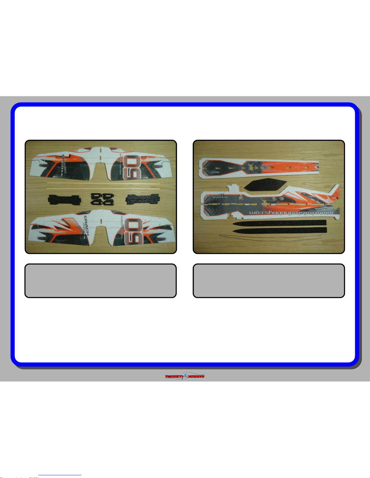
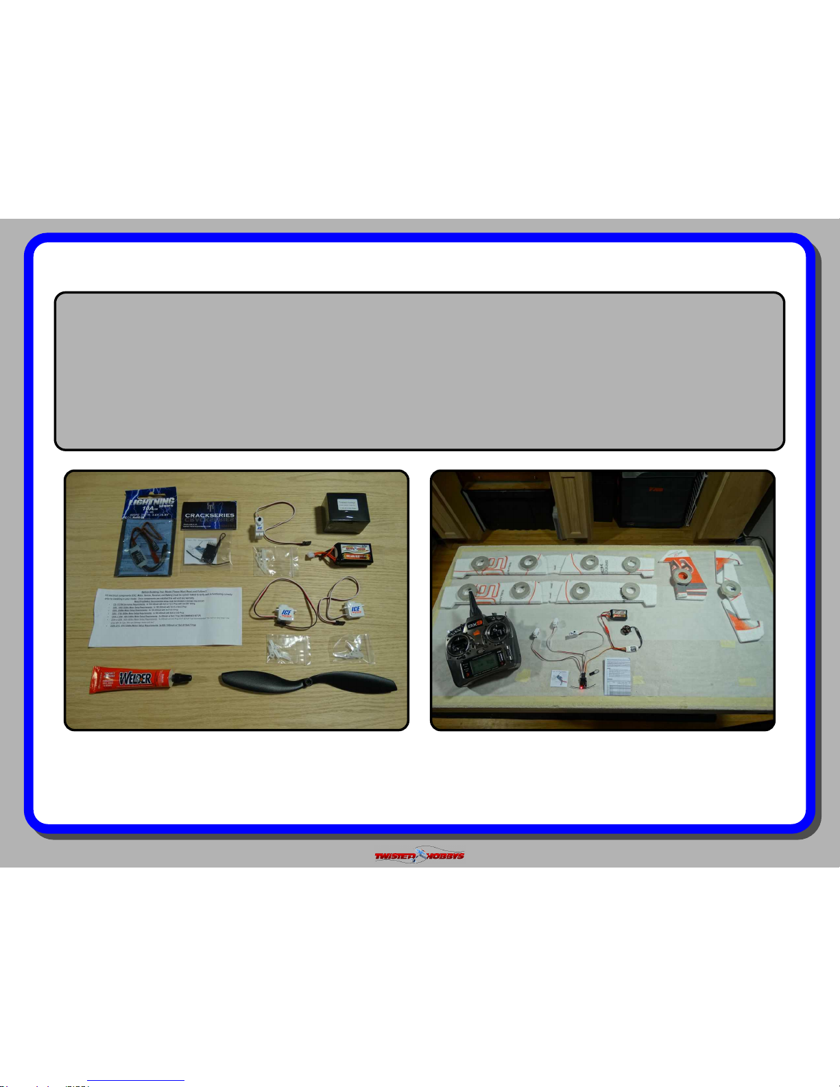
kit contents
Fuselage Parts
Wing Parts
Double check that you have all the above pictured items. Note -
Some kits might have slight deviations from the above pictured items.
Page 5
Rev: 2015.09.18.v01a
page 5
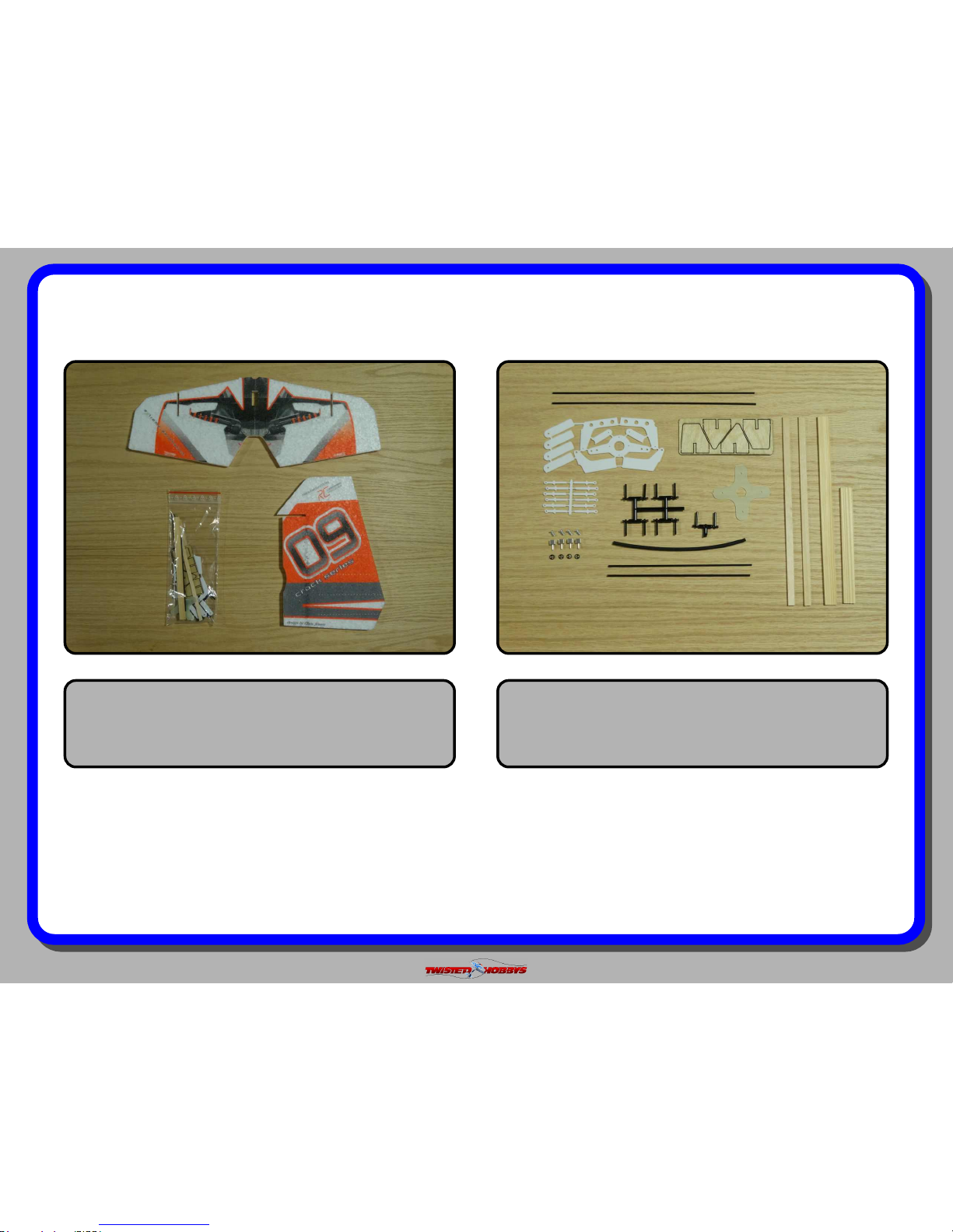
kit contents (cont.)
Hardware Kit Detail
Tail Surfaces & Hardware Kit
Double check that you have all the above pictured items. Note -
Some kits might have slight deviations from the above pictured items.
Page 6
Rev: 2015.09.18.v01a
page 6
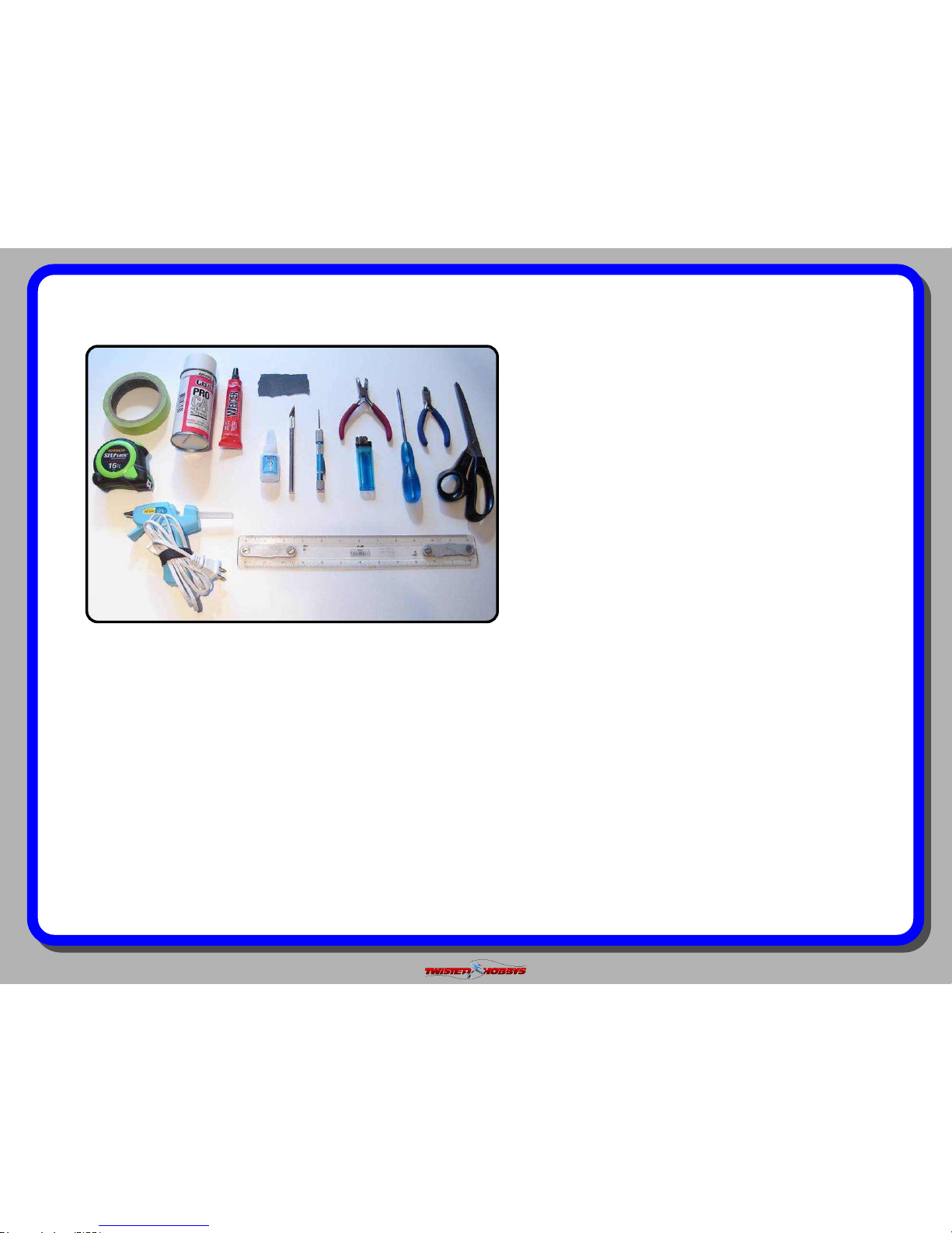
TOOL AND ADHESIVES NEEDED
Tools shown and listed are suggestions only.
Depending on your building technique you may not
need everything indicated – and/or – you may find that
other tools available to yourself may be of benefit to
your Build.
It is also recommended that you have a flat building
surface, one that will accept stick pins and push pins.
An Acrostic Ceiling panel from your local hardware
store fits this bill nicely, and will lay flat on your work
table. Over size / long push pins are available at your
local craft store. These two items are by no means
required, but will aid in the building process, and can
be used for future projects
Lighter
Small Drill Bits
Tape Measure and Ruler
Black Sewing Thread
Welders Glue
Hobby Knife w/new Blade
Needle Nose Pliers
Wire Cutters
Low Temp Hot Glue Gun
Course Sand Paper
Scissors
Small Phillips Screw Driver
Thin and Medium CA
CA Applicator Tips
Activator
Page 7
Rev: 2015.09.18.v01a
page 7
the build
CONSTRUCTION METHODS:
Building surface should be at least 2ft x 4ft and at. Weights or some small heavy objects will be handy for holding things in place
during the time glue is setting.
Welders glue is used for FOAM TO FOAM joints. Thin and Medium CA are used on the PLASTIC TO FOAM and CARBON TO FOAM
joints. When using the Welders glue for a butt joint, apply a thin lm to each surface, allow to sit for approx ve minutes and
then assemble. Note that this method will create a nearly instant bond, so locate carefully when bringing the two pieces together. If
alignment is necessary or a slip joint, do not allow the glue to tack up, simple apply and join immediately, you will have several
minutes to locate the two parts before the glue sets up. In most cases the parts being glued can be handled with care in 30 minutes,
full cure is approx 24 hours.
The above picture items will be needed to nish the model.
A power combo (Twisted Hobbys’ Combo pictured above), a
battery and a fresh tube of Welders. Note - the Battery,
Receiver and Welders are NOT part of the power combo,
everything else shown is.
Start the build by locating the two wings, the elevator and
the rudder. Fold back as shown and weigh them down for
about an hour to loosen up the hinge area. Now is also a
great time to setup your radio and to test that all your
electronics are functioning properly.
Page 8
Rev: 2015.09.18.v01a
page 8
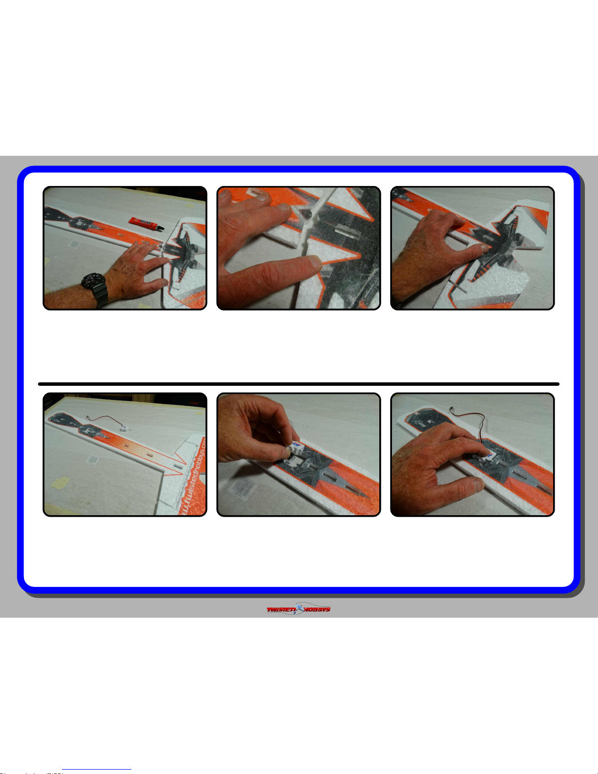
Find the horizontal fuselage piece and
the elevator. Join them together using
the Tack Up Method.
Notice that the two parts are “keyed” to
insure proper orientation.
Once the glue has tacked up, bring the
two pieces together, press rmly to get
a good bond.
Press the servo into the cut out. It will
stick up a little on the near side. Servo
arms will be install later. They would
just get in the way at this time.
Install the servo as shown, from the
underside/bottom of the horizontal
fuselage piece. Note - no glue at this
time, gluing the servos in will be done
towards the end of the build.
Flip the assembly over and locate your
elevator servo. If using the power
combo servos, the cut out will match
perfectly, if using other servos, some
trimming may be necessary.
Page 9
Rev: 2015.09.18.v01a
page 9
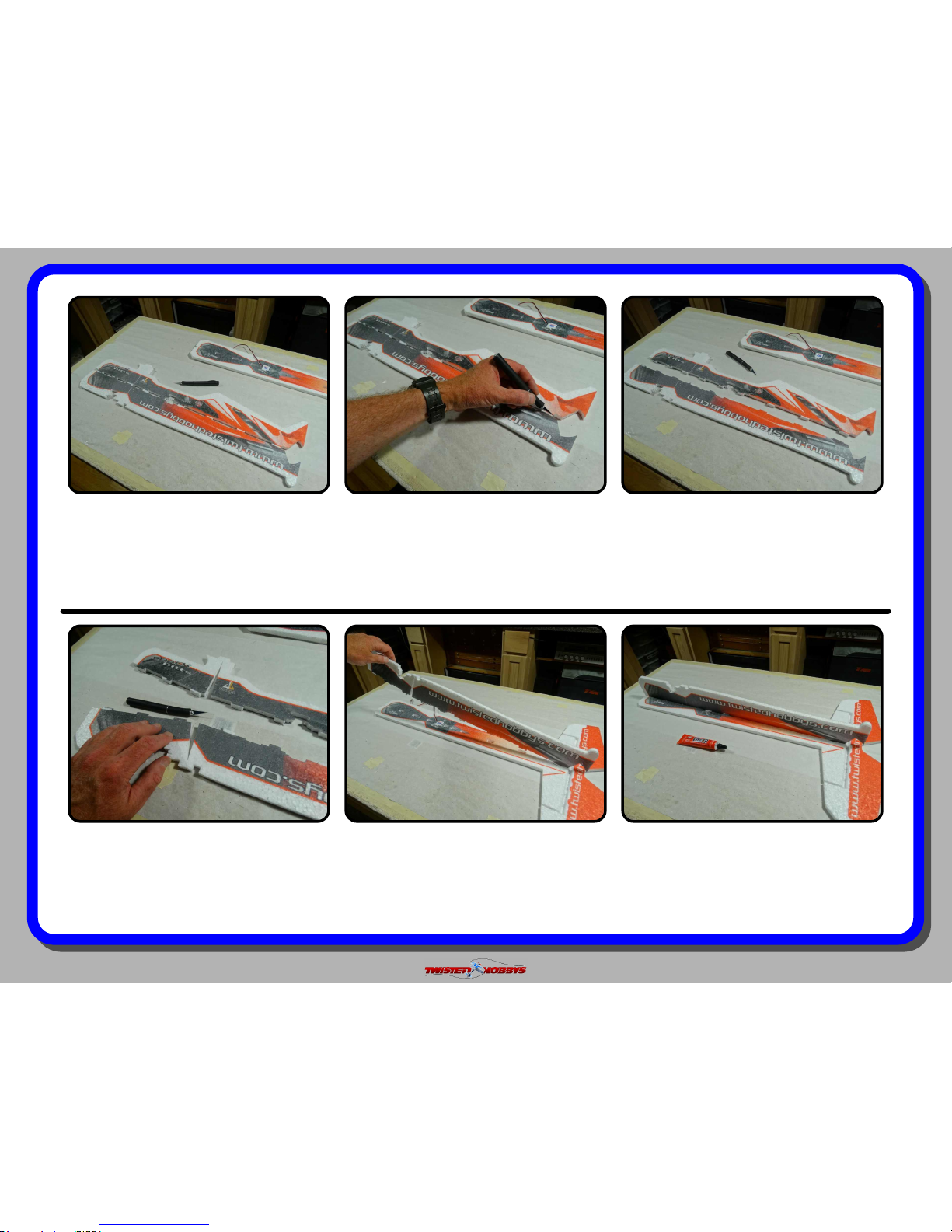
Locate the vertical fuselage section, and
put a fresh blade in your hobby knife.
Split the vertical fuselage section down
the center of the tabs. Note, the tabs
have small “V”s cut in them to help
locate the exact center.
Once all the tabs are split, you should
have something like pictured above.
Once you are satised with the test t,
separate the two pieces and re-
assembly using the Wet Method. Make
sure and apply glue to all the mating
surfaces and tabs.
Test t the lower vertical fuselage to the
horizontal assembly as shown. All tabs
should fully engage, and the two pieces
should be square to each other.
Split/Separate the small tab for the slot
shown above so that it is free as
pictured.
Page 10
Rev: 2015.09.18.v01a
page 10
Make sure all the tabs are fully seated
as was done with the test t, wipe away
any extra glue and weigh down so that
everything will dry at.
While the glue is still wet, check for
squareness and tweak a little as
needed.
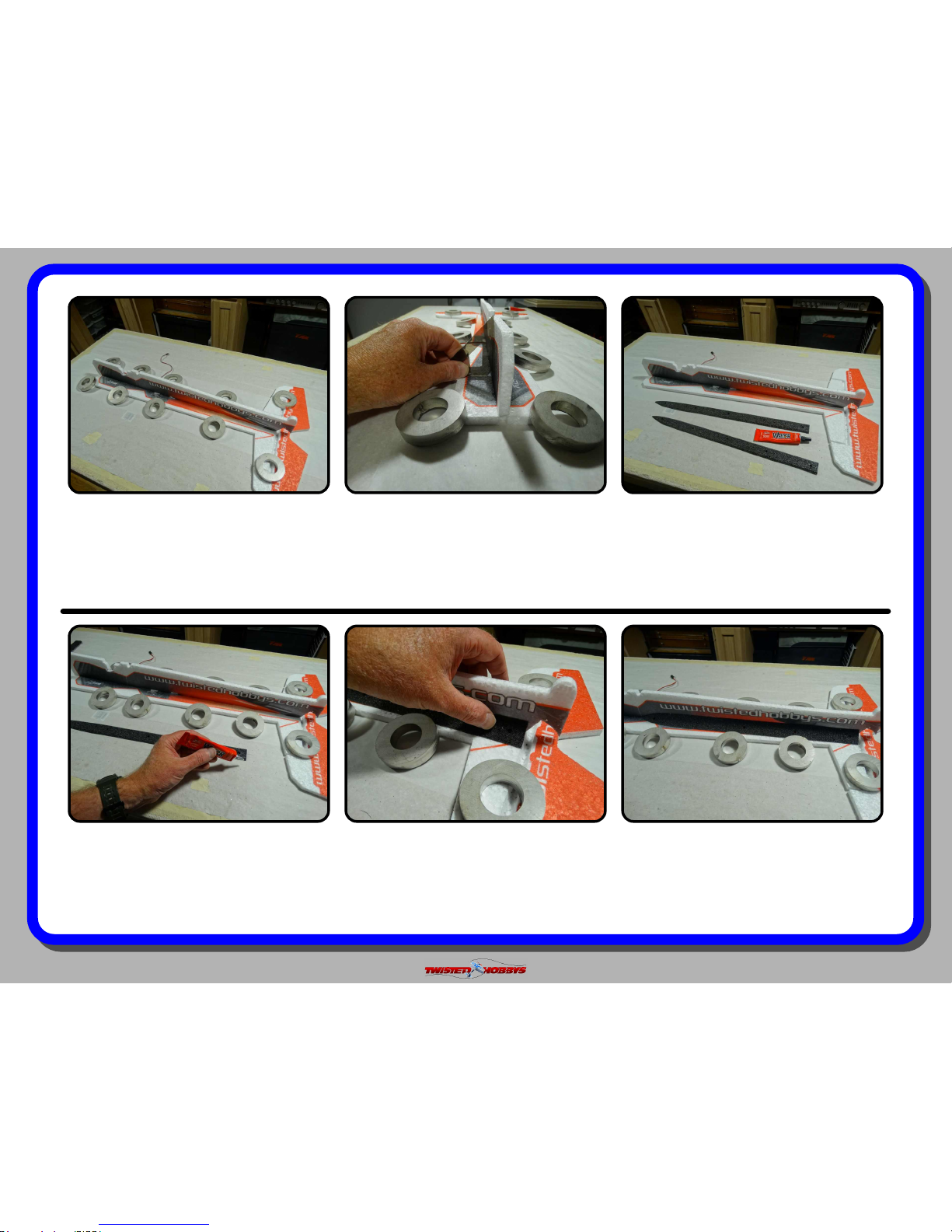
Locate the beveled foam trusses as
shown above.
Make sure there is a good bond. Use a
gentle touch when pressing the truss to
the fuselage. Pressing too hard will
cause the fuselage member to be out of
square.
Align the square end up with the edge
of the hinge relief as pictured above,
and attach the truss at 45 degrees to
the two fuselage members.
Stating with the side shown, apply a
medium bead of Welders the entire
length of the beveled area.
Page 11
Rev: 2015.09.18.v01a
page 11
Next is the far side, apply a medium
bead of Welders as with the other side,
but leave approx 4in free of glue on the
pointed end.
Attach the truss like was done on the
other side and note that there is approx
4in free of glue. This will allow access to
all the wires and will be secured to the
fuselage in a later step.
Make sure the two fuselage pieces are
still square to each other, allow the glue
to dry before moving on to the next
step.
Locate the top vertical half of the
fuselage. Test t, make sure that all the
tabs and slots are able to fully engage.
Make sure the wire does not get
bunched up under the servo in the hole
and that the servo is fully installed and
sitting rmly on it’s anges as pictured
above. Do Not Glue at this time.
Locate the rudder servo. If using the
Twisted Hobbys power combo servos,
no trimming will be need. Fish the wire
thru on the same side as the elevator
wire, and press the servo into it’s slot.
Page 12
Rev: 2015.09.18.v01a
page 12
Once happy with the t up, remove it
and apply a medium bead of Welders to
the mating surfaces. Avoid the servos
and areas around were the slits are in
the vertical fuselage pieces.
Starting from the front... align the nose
surfaces and work towards the tail
engaging the slots along the way. Press
and wiggle to make sure the tabs are
full seated into their respective slots.
The nose surfaces should all be ush
as pictured above. In a later step, this
is where the motor mount will attach
to, and it is important that they are
even to create a at surface.
Locate the two wood fuselage stiffeners
as pictured above. They should be
approx 2x9x90 and 2x9x150
millimeters.
Once happy with the squareness. Set
the assembly aside to dry. Stand the
assembly up as shown, this will avoid
any awkward stress to the airframe
while the glue is drying.
While the Welders is still wet, check for
squareness along the length of the
fuselage. Tweak as needed for a nice
and true assembly.
Page 13

Rev: 2015.09.18.v01a
page 13
Stick the longer of the two pieces of
wood thru the reward slot in a diagonal
fashion, right at the intersection of the
two fuselage pieces.
Position so that the length of wood
matches the approx length of the slot in
the foam.
Apply a thin coat of Welders to both
sides of the exposed wood stiffener.
Also squeeze some Welders into the
slots.
Apply a thin coat of Welders to both
sides of the shorter fuselage stiffener.
Make sure the stiffener is centered in
the foam and wipe away any extra glue
that is left on the surface of the
fuselage pieces. Use a paper towel and
only make one pass.
Press the wood stiffener into position as
shown, adjusting it’s position up or
down as needed to match the exact
length of the slot in the foam.
Page 14

Rev: 2015.09.18.v01a
page 14
Also squeeze some Welder into the slot
in the fuselage.
Install the stiffener into the fuselage
from the same side that you applied the
glue from.
Wipe away any extra glue with a paper
towel, and again, only one pass.
Multiple passes will ruin the printed
graphics.
With your hobby knife remove the tabs
and scrap material from the slot
cutouts of each of the wing.
Locate the two wings, wing struts and
wood spars as shown. Wing spars are
approx 23.6 inches long and the spars
for the struts are approx 5.9 inches
long.
Check for squareness in the area of the
stiffeners and adjust if necessary. Set
the assembly aside some where safe to
dry... stand it on it’s nose like what was
done previously.
Page 15

Rev: 2015.09.18.v01a
page 15
Once all the tabs and scrap material is
removed, you should be able to spread
the wing as shown above.
Apply a medium bead of Welders to
each side of the wing spar.
Spread the wing, and while keeping the
wing slot spread, lower the spar into
position, and then allow the foam to
relax.
Repeat with the other wing and then set
aside with weights and/or stick pins
and allow them to dry completely before
handling.
Wipe away any glue the squishes out.
Make sure and only do a single pass,
multiple passes will wreck the printed
graphics.
Make sure the spar is ush with the
surface of the wing. Press together
along the length of the wing to ensure
that there is a good bond between the
wing and the spar.
Page 16

Rev: 2015.09.18.v01a
page 16
As with the wing spars, apply a bead of
Welders to both sides of the strut spar.
Spread the strut as shown and insert
the spar.
Push it in all the way, making sure that
it is ush with both sides and wipe
away any extra glue.
While all that is drying, locate the horn
kits from your servos, the plastic horn
set that came with the kit, and the
adjustable links as shown above.
Repeat the process with the other side.
Note there is a left and right, but they
are symmetrical so it does not matter
how you build them.
Set aside with weights and/or stick
pins and allow to dry.
Page 17

Rev: 2015.09.18.v01a
page 17
If using the power combo servos you
should have stock horns like pictured
above, if using other servos, nd the
horns that came with them that are
similar.
From the under side of the stock horn,
apply some Welders to each of the
arms.
Install the differential horn as shown, if
the center hole is a little big, just center
it in the opening, if is not super critical,
just get it as close as you can.
Repeat the previous two steps with the
other tail servo horn and set all the
items aside to dry.
Above picture shows the extension
attached to the horn from the under
side and butted all the way up against
the center part of the stock horn.
Same basic process for the tail servo
horns... apply some Welders to the
under side of the stock horn and attach
the extension.
Page 18

Rev: 2015.09.18.v01a
page 18
Locate the two aileron control surface
horns and adjustable link pieces as
shown above. Note that the aileron
horns are the ones like pictured above
with the lightening holes.
Install the main adjustable link part
into the hole as shown. Note - it is
important to make a LEFT and RIGHT
version.
Press on the keeper clips with the
cupped side installed as pictured above,
repeat this for both horns, again
remembering that there is a left and
right.
Squeeze some Welders into the slit.With a sharp hobby knife, nish cutting
the slot all the way thru.
Next the gang horns will be installed on
the trailing edges of both wings. There
are pre-cut slots on the sides pictured
above, but they need to be nish cut all
the way thru.
Page 19

Rev: 2015.09.18.v01a
page 19
Put a medium skim coat on to both
sides of the gang horn.
Slide the gang horn into the slot. Make
sure that it is ush with both the upper
and lower surface of the wing.
Position the gang horn far enough in so
that it is ush with the trailing edge of
the wing as pictured above.
Aileron control horns are to be installed
next. These install into the top surface
of the bottom wing. there are pre-cut
slots, just cut all the way through like
was done on the gang horns.
Repeat with the remain three positions.
Note that the precut slots are on the
top of the bottom wing, and the bottom
of the top wing, as pictured above.
Wipe away any extra glue.
Page 20

Rev: 2015.09.18.v01a
page 20
Squeeze some Welders into the slot. Put a medium skim coat on both sides
of the horn in the area that gets buried
into the wing.
Install the horn into the wing. Note that
the main part of the adjustable link
should be facing outward
Repeat with the other side. Again notice
the orientation of the adjustable links.
Wipe away any extra glue.
Flip the wing over and check to see that
the prole of the horn matches the
prole of the hinge cut out. This
indicates that the horn is in the proper
position.
Page 21

Rev: 2015.09.18.v01a
page 21
Install the rudder control horn. Again,
as with the ailerons there is a precut
slot on the side shown that needs to be
cut all the way through.
Squeeze some Welders into the slot.
Note that the horns to be used on the
rudder and elevator are the same, and
they are the ones without the lightening
holes.
Apply a medium skim coat of Welders
to both side of the horn base.
Wipe away any extra glue that might
have pushed out.
Check on the back side like was done
on the ailerons to make sure the prole
of the horn matches the prole of the
hinge cut.
Slide the horn into the slot as shown.
Page 22

Rev: 2015.09.18.v01a
page 22
Repeat the last six steps for the
installation of the elevator horn.
Locate your aileron servo, and judge
whether or not the cut out in the lower
wing needs to be enlarged. In the case
of the power combo servos, the cutout
will need to be widened slightly.
Use a straight edge to modify the size of
the cut out.
The pointed one is installed on the
lower part of the fuselage.
Locate the small wood fuselage
doublers as pictured above. Note that
there are two different kinds.
Test t. Ideally the servo should t
snug. Not too tight and not loose. Once
happy with the t, remove the servo it
will be installed in a later step.
Page 23

Rev: 2015.09.18.v01a
page 23
And the one with the blunt end installs
on the upper part of the fuselage.
Apply a medium coat of glue to each or
the parts and install them into their
appropriate positions as just
mentioned.
Correct position is such that the edges
of the wood match the edges of the
foam and that the slots are aligned.
Size the cut out in the top wing as well.
Ideally it should be a snug t.
Once the glue has dried on the
doublers, test t into the cut out in the
wing. The slot will need to be widened a
little to account for the thickness of the
doublers. Do not remove too much.
Correct postion for the lower doubler.
As with the upper doubler, the edges of
the wood should match the edges of the
foam and the slots should be aligned.
Let these dry before proceeding.
Page 24

Rev: 2015.09.18.v01a
page 24
Once happy with the tment of the
upper and lower wings, the bottom
wing will be attached rst. Apply
Welders to all the mating surfaces. Note
avoid glue in the servo hole.
Slide the piece together. Assembly
should be done on a nice at surface.
Note that the tail skid bump helps to
position the fuselage at the correct
angle, and nose should hang off table.
Sight down the front of the airframe
and make sure that every thing is nice
and square and level.
Install the wing strut. Use a square to
position the strut square to the surface
of the wing.
Put some Welders into the slots and the
mating area just behind and in front of
the slot.
Wing struts are next. Note that they
lean towards the front of the aircraft.
Page 25

Rev: 2015.09.18.v01a
page 25
Repeat the process on the other wing
strut. Put some weights on the wing as
shown to keep things nice and at and
let the assembly dry before handling.
Once the glue has dried on the lower
wing, the top wing can be attached. Put
some glue in the strut slots and other
areas where the two pieces meet up.
Lower the fuselage onto the upper wing
as shown. Note that the airframe is
upside down for this step
Let the assembly dry before additional
handling. Note that the tip of the stab is
used like the tail skid bump was used
when doing the lower wing. This is by
design and positions everything true.
Check for squareness and tweak a little
if needed. Note that the assembly
should go together pretty square, if it is
not, check to see if there is binding or
stress somewhere.
Make sure the outer struts and center
fuselage strut are all fully engaged.
Page 26

Rev: 2015.09.18.v01a
page 26
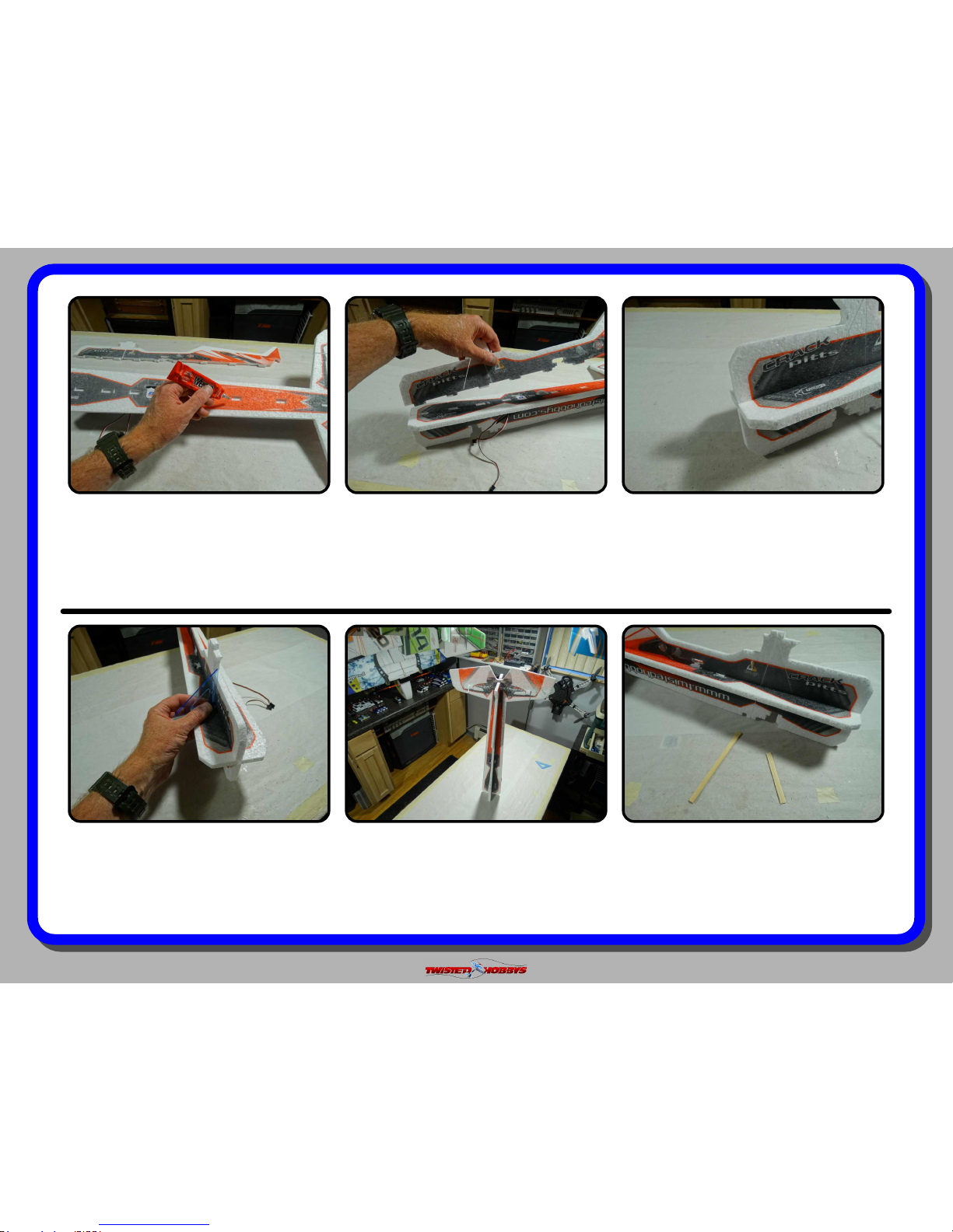
Once the wings and struts have dried
the tail and canopy can be attached.
Tack up method will be used for both.
Apply a medium skim coat to the
rudder and mating surface of the stab,
and let dry for approx 10 minutes.
Bring the two parts together. Take care
to get the alignment of the two pieces
just right. The bond will be instant and
there will be no opportunity for
adjustment.
Bring the two pieces together, and
again use care to get the proper
alignment as the two pieces come into
contact with one another.
Repeat the process for the Canopy. A
medium skim coat on both mating
surfaces. Let tack up for approx 10
minutes.
Press the two pieces rmly together to
ensure a good bond for the length of the
joint.
Page 27

Rev: 2015.09.18.v01a
page 27
Press the two pieces together, and
double check that the bond is good for
the length of the joint.
Locate the motor mount as shown
above and with a le or some coarse
sandpaper, roughen up one side.
Tack up method will be used to attach
the motor mount, so apply a medium
skim coat to the roughened side of the
motor mount and the matching area of
the aircraft nose.
Installation of the aileron servo is next.
If you are not sure whether the servo is
centered, plug it all in as shown to nd
the center.
Firmly press the two pieces together
and check that the bond is secure.
Once the glue has tacked up, bring the
two pieces together.
Page 28

Rev: 2015.09.18.v01a
page 28
Remove the servo horn if it was
installed and angle the servo into its
pre-cut slot. Power combo servos
should t perfectly. others may need
some trimming.
It will take a little pressure and nesse
to get the servo to pop in. Once in
position it should look something like
pictured above.
Without distrubing the center pisition
of the servo’s output shaft, install the
horn so that it is perpendicular to the
fuselage, with the tip pointing towards
the nose of the aircraft
Note that the snap links have a “U”
shaped cross section that will saddle
the control during attachment. Also, it
should be noted that these are very soft
plastic and will melt easy if over heated.
Locate the two long thin rods, the two
shorter thick rods, plastic snap links
and tubing. Cut the tubing into 1/2”
long pieces. Welders or CA can be used.
CA used in this manual.
Install the servo horn screw and return
the servo to it’s operational position.
Page 29

Rev: 2015.09.18.v01a
page 29
Starting with the aileron control rod
(shorter thick rods), position the snap
link and a piece of tubing as shown.
With a heat gun, hair dryer or lighter,
shrink the tubing. Use caution, the
snap links are easily damaged from too
much heat.
Apply a drop of CA to each end of the
shrink tubing and let it wick in.
Snap the plastic link into the outer hole
of the aileron servos horn. In this case
snap in from underneath in the view
above. Don't worry about the extra rod
length or set screw at the moment.
Slide the free end of the control rod
thru the hole of the adjustable link on
the aileron control surface.
Spray with Kicker. Repeat for the other
aileron control rod as well as the two
long thin tail control push rods.
Page 30

Rev: 2015.09.18.v01a
page 30
Repeat the process with the other side. Locate the tail servo arms and
adjustable link pieces.
Attach the adjustable links as pictured
above. Notice the orientation of the
links and keepers. This is important,
make sure it is right, these can not be
dis-assembled.
Locate the push rod guide tree and snip
all the parts free.
Repeat with the elevator servo. Again,
make sure the servo is electronically
centered. Install the servo horn screw.
Starting with the rudder servo, make
sure it is centered and attach the horn
as near perpendicular as possible.
Install the servo horn screw.
Page 31

Rev: 2015.09.18.v01a
page 31
Starting with the elevator side, install
all the guides into the precut holes. A
ashlight can be used to nd the holes.
Make sure they are in line and put a
drop of CA at the base of each.
Repeat with the rudder side.
Install the elevator control rod as
shown with the snap link end attached
to the elevator surface horn, and the
free end thru all the guides and also
thru the hole of the adjustable link.
With the servo still centered, also
center the control surface and install
the adjustable link’s set screw. Do not
over tighten, doing so will crush the
carbon and make it weak.
Repeat with the other side.
Close up of the free end sticking thru
the hole in the adjustable link. Don’t
worry about the set screw or trimming
at this time.
Page 32

Rev: 2015.09.18.v01a
page 32
Repeat the process with the other side,
again making sure that the servo and
control surface are centered.
Snip off any extra length of the control
rod. Leave about 1/4” past the end of
the adjustable link.
Aileron gang control rod will is next.
Locate the longer thick rods, four snap
links and four 1/2” long pieces of
shrink tubing. Heat shrink the ends on
like before, but NO GLUE at this time.
It may be necessary to trim the rods a
little to get the exact length, just slide
the link and tubing off, snip, and slide
back on. Once happy with the length,
wick some CA into the tubing ends.
With the nose of the airframe over the
edge of a table to clear the aileron’s
servo, make sure the bottom ailerons
are ush to the table and check that
the snap links link up with the holes.
With tape or other means, make sure
the upper wing’s ailerons or level.
Page 33

Rev: 2015.09.18.v01a
page 33
Double check the length, and
orientation of the bosses, adjust as
needed and wick CA into the other end.
Snap the links into the gang horns.
Repeat for the other side.
The next step will require Blenderm
and Welders. Although not required, it
is highly recommended. Cut 4 strips
that are approx 1.50” long.
Locate the motor you will use and it’s
associated hardware.
Let the glue tack up for about 5
minutes than apply the tape tabs.
Again, one tab for each motor mount
leg.
The Blenderm tape will wrap around
each leg of the motor mount and attach
to the the fuselage. Apply a skim coat of
Welders where the tape will contact,
this gives a much stronger bond.
Page 34

Rev: 2015.09.18.v01a
page 34
Mount the motor as shown, make sure
the leads are on the side of the airfame
that you want to install the ESC onto,
in this case, far side - bottom.
Welders or low temp hot glue can be
used to attach the ESC where desired.
Decide how you want to tidy up all the
wires, use a little hot glue and/or zip
ties. Now is also a good time to put a
bead of Welders around all the areas
you can reach of the servos.
Welders or CA can be used to attach
them. If using Welders lay down a small
bead and install the SFG, if CA’ing
install the SFG and then CA and hit
with Kicker.
Cut the SFG’s from the tree and split all
of them as pictured above.
Locate the Side Force Generators. Note
that they are NOT symmetrical. The
smaller surfaces will go to the insides of
the wings.
Page 35

Rev: 2015.09.18.v01a
page 35
Repeat the process for the other three
side force generators. Make sure they
are square to the wing and parallel to
the direction of ight.
Picture above shows how the small
surface of the SFG’s is installed
towards the insides of the wings.
Finish up the program in your radio, ie,
set the subtrims so all surfaces are
neutral. Set the Servo End Points, Dual
Rats and Expo to suit. See the Control
Throws Section for guidelines.
This completes the build of the airframe with the included kit items. There is
an optional Landing Gear set, the directions of which can be found near the end
of this manual.
Please visit www.TwistedHobbys.com for other accessories and aircraft.
There are several online resources and forums for this model as well. It is
suggested that you visit the RC Groups Thread for this model for additional
information, it is a great resource for questions and insight to this aircraft.
Page 36

Rev: 2015.09.18.v01a
page 36
center of
gravity
control
throws
C.G. - 185mm from nose of aircraft
Locate all the electronic to achieve
indicated CG point. Use Velcro for
initial ights for battery mounting and
experiment with it’s position until you
have determined the best spot for your
ying style. For best 3D performance,
balance for level ight upright and
inverted with little to no elevator input.
Also power off down line should be
straight down without any pull or tuck.
Extreme & 3D
Ailerons: +/- 40 deg
Rudder: +/- 45 deg
Elevator: +/- 45 deg
Expo to suit (40% to 60%)
Beginner & Sport
Ailerons: +/- 20 deg
Rudder: +/- 20 deg
Elevator: +/- 20 deg
Expo to suit (15% to 30%)
In order to achieve the control throws as
described for “Extreme and 3D, it is
imperative that the control surfaces,
linkages, rod ends, etc, all move freely
over the entire range, including range
end points.
Failure to do so will result in damage to
either the servos or mechanical
components
185 mm
Page 37

Rev: 2015.09.18.v01a
page 37
pre-flight & testing
Motor: Should run smoothly at all stick positions, and transition
smoothly from low to high RPM. If the motor is turning
backwards, reverse two of the three wires between the motor
and ESC. Check that the screws holding the motor to the
airframe are tight and secure.
Flight Controls: Set all to neutral or level positions with sticks
in the neutral positions. Ensure that all controls and linkages
move freely. Double check that all hinged areas are free from
rips or tears. Verify proper control surface directions. Right Roll
is – right aileron up, left aileron down, Left Roll is left aileron up
and right aileron down.
Batteries: Should be fully charged prior to each flight. Watch
tra n smi t ter b a tte r y lev el and f ollo w manu fact ures
recommendations. Motor battery should not be drained any
further than recommended by the manufacture, use a timer to
prevent an over discharged condition.
Radio: All trims should be set to neutral and throttle in the low
position. Check that rate switches and mixes are set properly.
Range Check: With and without the motor running per radio
manufactures instructions. If there is insufficient range or
significant reduction with the motor running, resolve and re-test
before flying.
The fi rst flights should be done with the CG at the
recommended position, and reduced control rates until
comfortable with your handling of the aircraft. As your
experience with the aircraft grows experiment with different CG
points and control rates. After all flights, check the aircraft over
for damage and/or other items that may adversely affect flight
performance.
This Extreme 3D Plane is a full performance aircraft and will
provide hours of entertainment, including the occasional crash.
If, as the result of a crash, the foam tears, simply glue with
Welders or CA. Many pilots prefer Welders because it remains
flexible after drying. CA however, is more suited for the “quick”
repair.
This aircraft can be flown indoors or outdoors. It is however
designed specifically for indoor flying and will be right at home
in the local gymnasium or other similar sized venue.
Storage
This EPP plane should be stored resting it's landing gear or
hung from the prop. Storing in other fashions that put stress on
the airframe could cause the airframe to distort. Storage in a
hot car could also cause damage.
Preght Checks Preght Checks
Be safe and enjoy, thank you again for purchasing a Twisted Hobbys’ Product!
Page 38

Rev: 2015.09.18.v01a
page 38
notes and s/u Sheet
Page 39

Rev: 2015.09.18.v01a
page 39
TIPS AND TRICKS
A good building surface is —drop ceiling“ panel from a local hardware store on a nice flat board
Use parchment paper between the areas being glued and your work surface
Heavy flat objects (like books, batteries, etc.) could be used to hold everything flat
When resetting your radio, start with all the ATV‘s or throw volumes at 100%.
Make sure you have set the direction of the servos correctly before attempting t o trim for zero position.
If possible try the servo horns in different locations to determine which position will require the least amount of
sub trim.
Installing the servo horns in thei r final location and attaching quick links to the servos may make servo
installation much easier later.
On the Orange Rx, the negative pin is the one closest to the flat side of the circuit board.
Keep a good supply of sharp knife blades handy when building a foamie airplane.
Use low temp hot glue for gluing electronics, this will allow for easy removal later if necessary. The low temp hot
glue can be “released” by painting” the glue bead wit h an alcohol soaked cotton swab a couple times.
A business card with the corners clipped off can be used as a small square.
Allowing the Welders glue to set for five minutes before assembly will shorten the tack up time, just be sure if
doing it this way that you get the parts into posit ion quickly, as the glue will start to bond on contact. Any joints
that you feel are going to require adjustment , it is best to assembly the pieces while the glue is wet. The Green
(high tack) masking tape works the best when used to clamp things together on an EPP foam airplane.
When gluing the rudder to the fuselage, stick pins could be used to ho ld in position if wanting to handle the
airframe before it is completely dry
A rotary tool with a cutting wheel could be used to produce grooves in fiber glass parts instead of coarse sand
paper. Use a hatch pattern. This creates more bonding area for the glue.
Page 40

Rev: 2015.09.18.v01a
page 40
With .076” drill, enlarge wheel axle,
carbon ber LG and wheel pant brace.
Install screw through wheel and spin
nut over other end, do not tighten nut
fully so wheel can spin, secure nut with
CA. Then install wheel spat as shown
an d a fu se suppo rt . Install t he
completed half through the fuselage.
Glue the wheel pants as shown.
Attach pant to brace as shown. Make
sure the wheel can roll freely. Repeat
for the other side.
optional landing gear
1
2
3
4
5
6
7
8
 Loading...