

Page 1

Rev: 2015.06.28.v01c
page 1
USA Distributor
Twisted Hobbys
www.twistedhobbys.com
Big Turbo Beaver
MOTOR: 1x 72g / 1000 to 1200kV Outrunner
ESC: 1x 30amp
SERVOS: 4x 14g / 2x 5g
PROP: 10x3.8 SF Prop
BATTERY: 3s / 1000-1350mAh
RADIO: 4 to 7 channel
WINGSPAN: 43-1/2”
LENGTH: 39-3/8”
AUW: 630g (depends on equipment)
Page 2

Rev: 2015.06.28.v01c
page 2
SAFETY NOTES
Before assembling and flying this model, read carefully any instructions and warnings of other
manufacturers for all the products you installed or used on your model, especially radio
equipment and power source.
Check thoroughly before every flight that the airplanes’ components are in good shape and
functioning properly. If you find a fault do not fly the model until you have corrected the
problem.
Radio interference caused by unknown sources can occur at any time without notice. In such a
case, your model will be uncontrollable and completely unpredictable. Make sure to perform a
range check before every flight. If you detect a control problem or interference during a flight,
immediately land the model to prevent a potential accident.
Youngsters should only be allowed to assemble and fly these models under the instruction and
supervision of an experienced adult.
Do not operate this model in a confined area.
Do not stand in line with, or in front of a spinning propeller and never touch it with any object.
IMPORTANT: PRIOR TO ANY ASSEMBLY
Please Note: after removing kit from shipping box, lay each piece flat on a
hard surface, this will allow the airframe to straighten out if lightly bent
from shipping. Do not worry since EPP is very pliable and can be bent back
if out of shape.
Page 3

Rev: 2015.06.28.v01c
page 3
TWISTED HOBBYS
Website: www.twistedhobbys.com – email: sales@twistedhobbys.com
Thank you for your purchasing a Twisted Hobbys‘ model. Please read through the entire manual before beginning to
build this model. If you have any questions please contact us at the above indicated email address.
WARNING INFORMATION
This R/C Aircraft is not a toy! Read and understand the entire manual before assembly. If misused, it c an cause serious bodily harm and
property damage. Fly only in open areas, and AMA (Academy of Model Aeronautics) approve d flying sites. Do not over look the warnings
and instructions enclosed or those provided by other manufactures’ products. If you are not an experienced pilot and airplane modeler you
must use the help of an experienced pilot or an authorized flight instructor for the building and flying of this model aircraft.
These instructions are suggestions only on how to assemble this model. There are other ways and methods to d o so. Twisted Hobbys has
no c ontrol over the final assembly, the materials and accessories used when assembling this kit, or the m anner in which the assembled
model, installed radio gear and electronic p arts are used and maintained. Thus, no liability is assumed or accepted for any d amage
resulting from the use of th e assemb led model aircraft or from this instruction manual including but not limited to direct, indirect,
incidental, special, and consequential damages. By the act of using this user-assembled product, the user accepts all resulting liability. In
no event shall Twisted Hobbys’ liability exceed the original purchase price of the kit.
SHIPPING DAMAGE
Twisted Hobbys checks each plane before shipping to ensure that each kit is in fine condition. We have no bearing on the condition of any
component parts damaged by use, modification, or assembly of the mod el. Inspect the components of this kit upon receipt. If you find any
parts damaged or missing, contact Twis ted Hobbys immediately. We will not accept the return or replacement of parts on which assembly
work has already begun. Twis ted Hobbys reserves the right to change this warranty at anytime without notice.
OUR MISSION
To provide the best products and service to our customers at the lowest prices pos sible. We take great pride in
our company, our commitment to customer service and in the products we sell. Our online store is designed
to provide you with a safe and secure environment to browse our product catalog.
Thank you for shopping with Twisted Hobbys!
Page 4
Rev: 2015.06.28.v01c
page 4
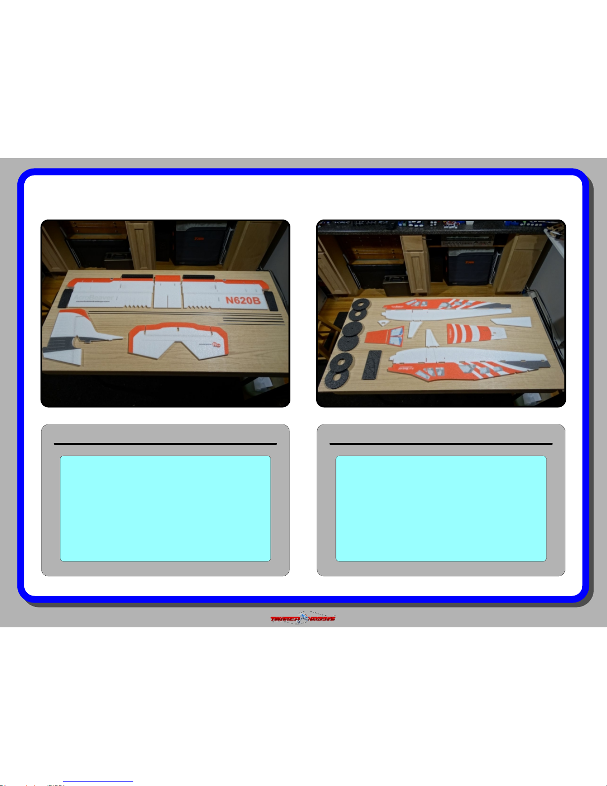
kit contents
Fuselage Parts
Double check that you have all the
above pictured items. Note - Some
kits might have slight deviations from
the above pictured items.
Wing, Tail Surfaces and Carbon Spars
Double check that you have all the
above pictured items. The Carbon
Bundle includes tail push rods and
wing spars. Note - Some kits might
have slight deviations from the above
pictured items.
Page 5
Rev: 2015.06.28.v01c
page 5
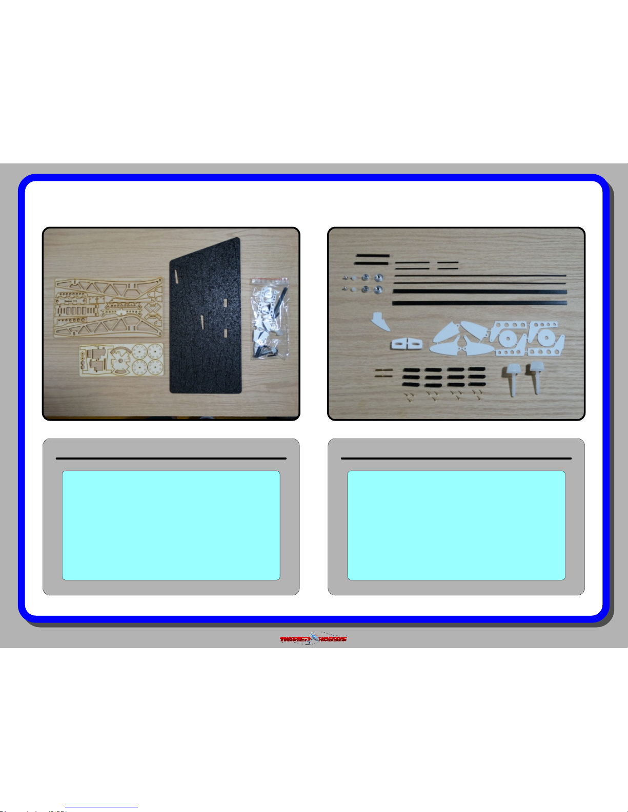
kit contents (cont.)
Hardware Kit Detail
Double check that you have all the
above pictured items. Note - Some
kits might have slight deviations from
the above pictured items.
Plywood, Foam and Hardware Kits
Double check that you have all the
above pictured items. The Hardware
kit items are detailed to the right.
Note - Some kits might have slight
deviations from the above pictured
items.
Page 6
Rev: 2015.06.28.v01c
page 6
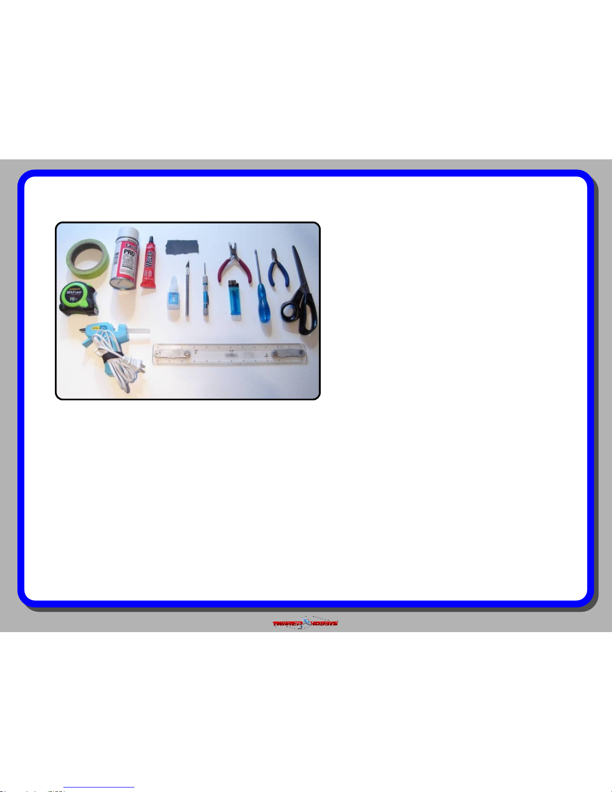
TOOL AND ADHESIVES NEEDED
Tools shown and listed are suggestions only.
Depending on your building technique you may not
need everything indicated – and/or – you may find that
other tools available to yourself may be of benefit to
your Build.
It is also recommended that you have a flat building
surface, one that will accept stick pins and push pins.
An Acrostic Ceiling panel from your local hardware
store fits this bill nicely, and will lay flat on your work
table. Over size / long push pins are available at your
local craft store. These two items are by no means
required, but will aid in the building process, and can
be used for future projects
Lighter
Small Drill Bits
Tape Measure and Ruler
Black Sewing Thread
Welders Glue
Hobby Knife w/new Blade
Needle Nose Pliers
Wire Cutters
Low Temp Hot Glue Gun
Course Sand Paper
Scissors
Small Phillips Screw Driver
Thin and Medium CA
CA Applicator Tips
Activator
Page 7
Rev: 2015.06.28.v01c
page 7
the build
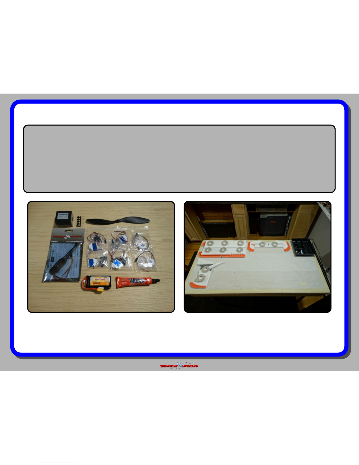
CONSTRUCTION METHODS:
Building surface should be at least 2ft x 4ft and at. Weights or some small heavy objects will be handy for holding things in place
during the time glue is setting.
Welders glue is used for FOAM TO FOAM joints. Thin and Medium CA are used on the PLASTIC TO FOAM and CARBON TO FOAM
joints. When using the Welders glue for a butt joint, apply a thin lm to each surface, allow to sit for approx ve minutes and
then assemble. Note that this method will create a nearly instant bond, so locate carefully when bringing the two pieces together. If
alignment is necessary or a slip joint, do not allow the glue to tack up, simple apply and join immediately, you will have several
minutes to locate the two parts before the glue sets up. In most cases the parts being glued can be handled with care in 30 minutes,
full cure is approx 24 hours.
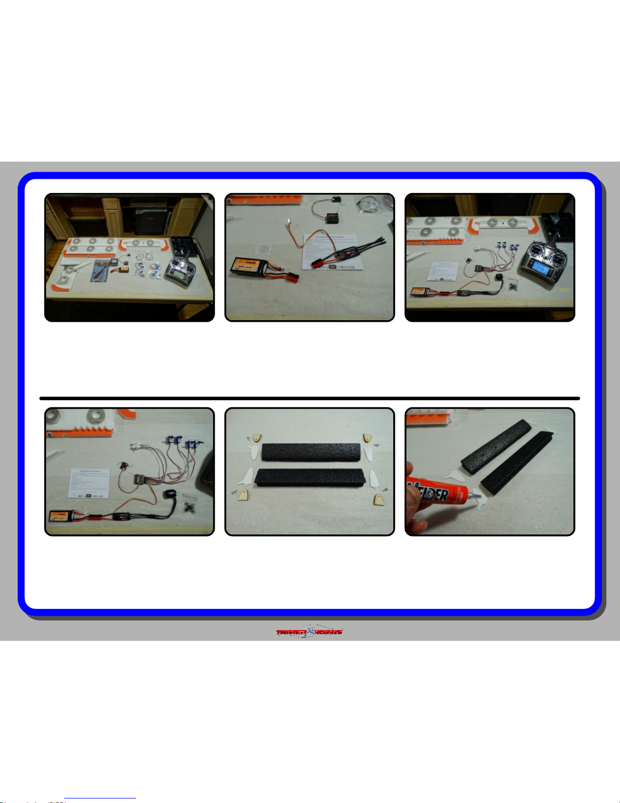
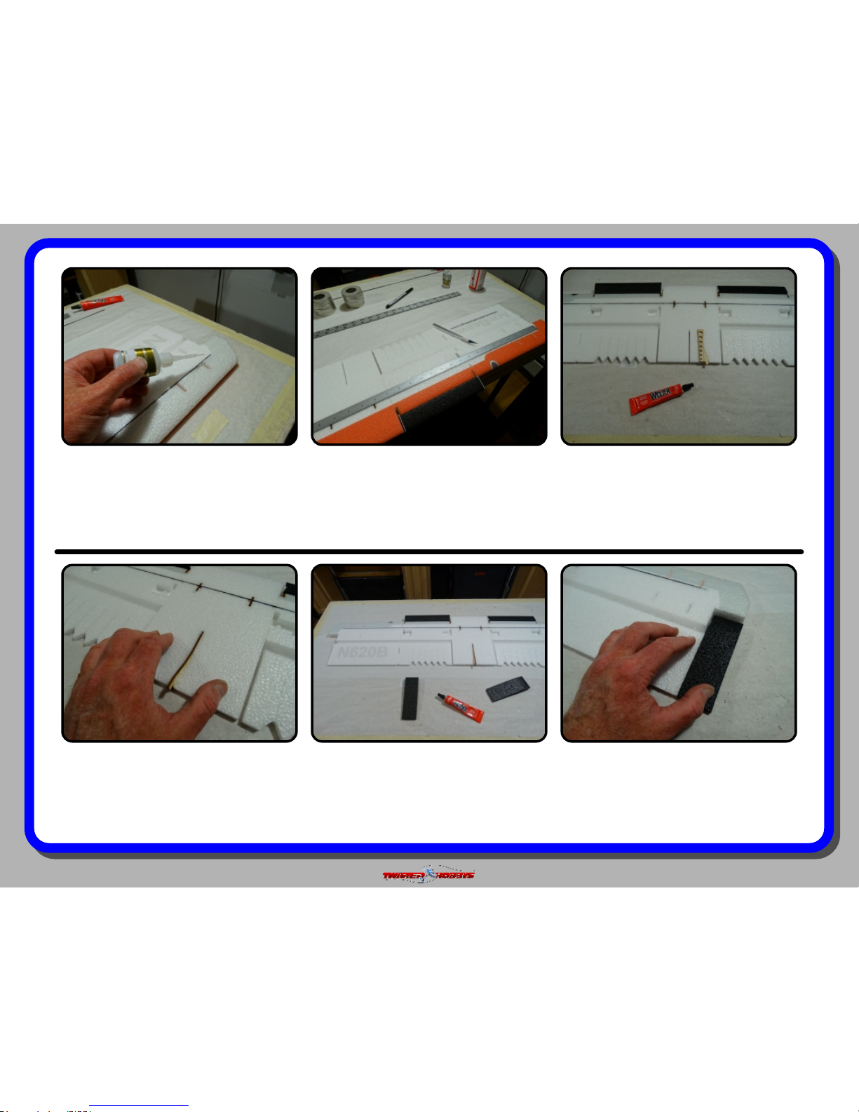
The above picture items will be needed to nish the model.
A power combo (Twisted Hobbys’ Combo pictured above), a
3s/1300mAh battery and a fresh tube of Welders. Note -
the Battery and Welders are NOT part of the power combo,
everything else shown is.
Start the build by locating the two wing halves, the elevator
and the rudder. Fold back as shown and weigh them down
for about an hour. This will loosen up the hinge line and
allow the surfaces to move much more freely. The wing
hinge will be stiff... work it slowly so it doesn’t tear
Page 8
Rev: 2015.06.28.v01c
page 8
While the control surface are relaxing,
gather up all your radio gear.
IT IS IMPERATIVE TO DO THE
NEXT COUPLE STEPS PRIOR TO
INSTALLATION!
Attach connector to the ESC that
matches the batteries you will use.
Note - if using the recommended
battery and ESC location you will need
to make an extension. See page 37.
Plug everything in, bind the radio per
mfg instructions and check that all the
servos operate correctly and smoothly.
Hang on to the motor near the wires,
and test it’s operation as well.
Using the “tack up” method apply a
skim coat to the mating surfaces.
Note - you have to build a Left and
Right had version. Take this into
account when applying the glue.
Locate the above items needed for the
Lead Edge Flap (LEF) assemblies.
Screws shown are the 4 tiny M2x5
screws that are located in the hardware
bag.
With many ESC’s it is required to
program throttle end points. Follow the
mfg instructions for this operation and
complete the process at this time.
Page 9
Rev: 2015.06.28.v01c
page 9
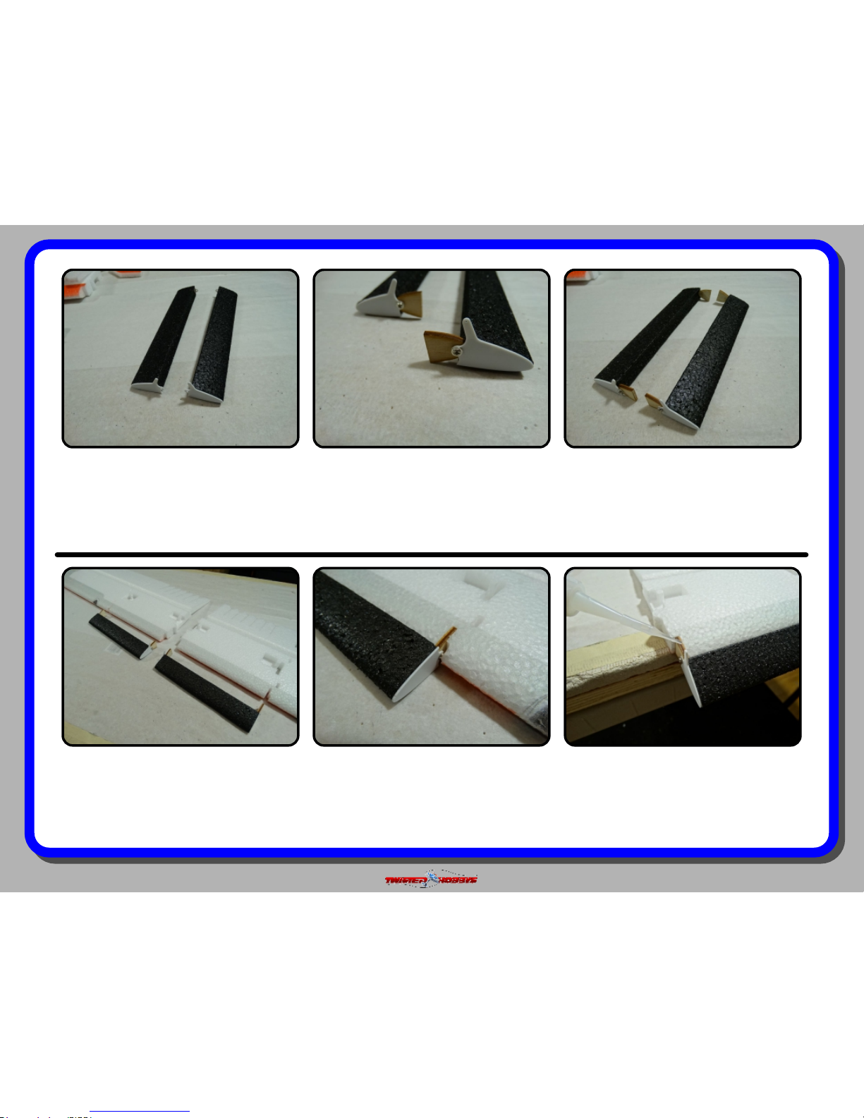
Attach the plastic pieces as shown,
lining up their proles with the prole
of the LEF. Again, be sure and make a
left and right version of these two
pieces.
With the M2x5 screws, attach the wood
pieces as shown. Note that they go on
the INSIDE of the plastic pieces. The
wood pieces must pivot, so do not over
tighten the screws.
When completed you should have
something that looks like the above
parts.
Using thin CA and kicker, glue the
wood pieces of the LEF to the wing, be
very careful that you do not get glue in
the area that pivots.
Fully engage the wood pieces and make
sure there is no binding of movement
when exercising the LEF.
Test t wood pieces of the LEFs into
their respective slots in the wings
leading edge. Note - the plastic piece
with the horn is INBOARD and on the
UNDER side of the wing.
Page 10
Rev: 2015.06.28.v01c
page 10
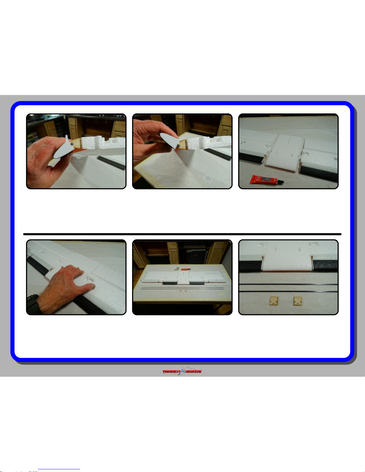
Make sure you have equal amounts of
up and down movement as shown in
this and the next picture.
Movement in the opposite direction
should be approx equal to the
movement in the previous picture. Note
this does not have to be exact, just
similar.
Apply a medium tack up coat to the
mating surfaces of the items shown
above. Note - the UNDERSIDE of all the
pieces should be facing UP.
In addition to the spars you will need
the above picture two items from one of
the wood kits.
Installing the 1x3x980mm carbon spars
in to the wing is next. Locate the spars,
these should just have been loose in
the box.
Once the glue has tacked up, join the
pieces together making sure that the
airfoil proles align as perfectly as
possible.
Page 11
Rev: 2015.06.28.v01c
page 11
The wood pieces will install into the
pre-cut slots pictured above. Welders
should be used for this.
Apply a Wet coat of Welders to both
sides of the part AND squeeze a little
into the slot area. If possible keep the
“notch” free of glue. Then slide the
wood piece in, arrow pointing forward.
Slide the wood piece in until it is ush
and wipe away any excess glue that
squeezed out
Once the whole length of the spar is
install, it should look similar to the
above picture.
Install the spar DRY. Make sure that
the slit you cut was “just” deep enough
so that the spar when fully seated will
be ush with the wings surface.
Next, cut a 3mm deep slit, centered and
long enough to accommodate the
carbon spar. Location front to back is
determined by the relief cut in the small
wood pieces just installed
Page 12
Rev: 2015.06.28.v01c
page 12
Once you are happy with the depth of
the spar, wick in some thin CA for the
entire length and hit with kicker.
Flip the wing over and repeat the
process on the top side.
Locate the wood piece shown above and
coat it with a medium amount of
Welders and with the nozzle of the tube
squeeze some Welders into the slot.
Once the Welders has tacked up, bring
the two pieces together. Align them on a
at surface and use the trailing edges
as reference.
Grab the black two counter balance
pieces that glue onto the end of the
ailerons. Coat the them mating surfaces
with a lm of Welders and let tack up.
Install the piece as shown, from the
under side. Make sure that ts ush on
the top side, and ush everywhere on
the bottom except where it gets wider
for the hook.
Page 13
Rev: 2015.06.28.v01c
page 13
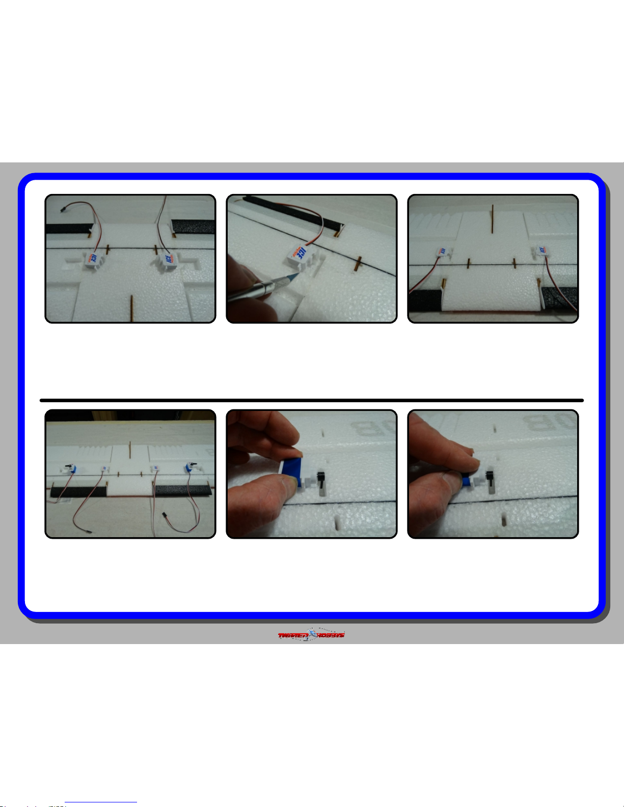
Locate the servos that will be used for
the LEF’s. Depending on the size servo,
you may or may not need to adjust the
size of the cut out.
Figure out where the slits need to go for
the ears of the servo, and adjust the
size of the pocket if necessary. Make
sure that the output arm of the servo
lines up with the horn of the LEF
Repeat for the other side. Some servos
may stick up a little from the surface of
the wing, this is ne.
Press the servo into position.Locate the slits for the servo tabs by
lining up the output shaft/horn with
the center of the slot in the wing as
shown above.
Locate the servos that will be used for
the ailerons. As with the LEF’s, the size
of servo being used will determine if
there needs to be any trimming of the
pre-cut pocket.
Page 14

Rev: 2015.06.28.v01c
page 14
Aileron servo installed. Repeat for the
other side.
Now you can route the wires towards
the cabin area. Route in such a way
that the left over wire will be the longest
in the general area where you plan to
locate the receiver.
In this build the position of the Receiver
has been determine to be near the
tailing edge of the wing, in the cabin
area, this will minimize the potential
need for extensions.
With the servo electronically center and
the LEF in it’s neutral position,
measure the distance from hole to hole
of the horns.
Locate the clevis and rods as shown.
The shorter rods are 1.5mm dia x
25mm long and the longer rods are
1.5mm x 45mm. Note these dimensions
may vary some from kit to kit.
Repeat for the other side, keep the slits
you cut to a minimum depth, all that is
needed is just enough to bury the servo
wire.
Page 15

Rev: 2015.06.28.v01c
page 15
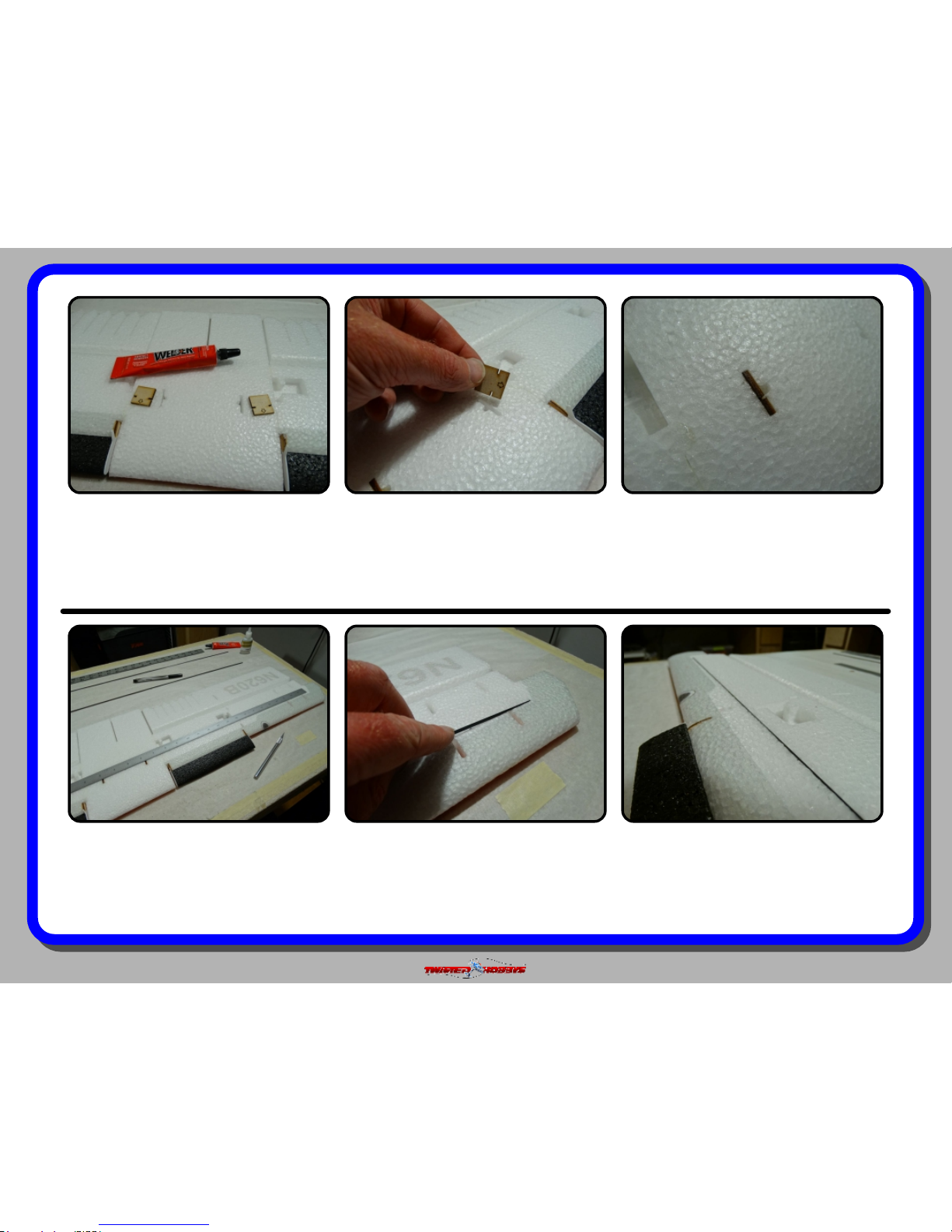
Duplicate the dimension in the holes
spacing of the clevises. Use medium CA
to secure the rod to the clevis. Do one
end rst than measure again. Make
sure the orientation is correct.
Attach the control rod between the
servo and the LEF. If it is slightly off
center, this can be adjusted with sub-
trim later when setting up the radio
program.
Repeat for the other side.
With the control surface and servo both
in neutral positions, measure from hole
to hole like was done with the LEF.
Put a skim coat of Welders on the base
of the horn, and squeeze some into the
slot with the nozzle of the tube. Install
the horn while the glue is wet and
position the horn as needed.
Next cut a slot in the wing for the
aileron control horn. Use a square to
get the slot in line with the servo arm.
Cut the slot so that the clevis hole in
the horn will be on the hinge line.
Page 16

Rev: 2015.06.28.v01c
page 16
Position the holes in clevises as you did
with the LEF and secure them to the
rod with medium CA. Make sure that
the orientation is correct.
Connect the control rod to the servo
and aileron control horn as shown. If
any adjustments are needed they can
be done later with subtrim.
Repeat the process for the other side.
This completes the Wing building, it
can be set aside for now and work on
the fuselage can begin.
With the nozzle of the Welder’s tube,
squeeze a small bead of glue into the
respect slots and install the strips as
shown while the glue is wet. Note - One
of the long ones is left out for now.
Locate two of the 1x5x300 carbon strips
and one of the 1x5x200 carbon strip.
Make sure the slot in the foam is deep
enough to receive each of the strips.
Now that the Wing is complete the
fuselage is next. Using the tack up
method, attach the landing gear
fairings as shown with the slots lining
up between the two pieces
Page 17

Rev: 2015.06.28.v01c
page 17
Use stick pins or weights to hold
everything at while the glue dries.
Once the glue dries from the previous
step, ip both pieces over and locate
the above pictured wood doublers.
Apply a medium bead of Welders on all
areas of the wood’s back side.
Locate the above pictured wood items
and the two small alum threaded insert
nuts.
Repeat for the other side and with stick
pins or weights, let the glue dry before
moving these pieces around. It is
important to make a left and right, and
that the wood is on the sides shown.
While the glue is wet, attach the
doubler as shown above. Note there are
two different slots in the foam and the
doubler that need to line up. Slide the
wood around until the slots match up.
Page 18

Rev: 2015.06.28.v01c
page 18
Fit the three center bridge pieces
together as shown above. It may be
necessary to sand of le on the mating
area.
Make sure the orientation of the three
parts is as shown in this picture and
the previous one
With thin CA and kicker, glue the three
pieces together.
Locate the body half shown above and
split it in the tabbed area. Using the
small points in the foam as a guide to
where the center of the tab is.
Repeat the process for the second nut
insert
With a little dap of Welders attach the
nut insert as shown. Keep the threaded
area free of glue.
Page 19

Rev: 2015.06.28.v01c
page 19
Install the cross members now in to the
slots of the part that was just
seperated. Note - this is a dry t... NO
glue at this time.
Find the motor mount in the wood kit
and remove it. Note - production kits
will have two different hole patterns to
accommodate different style motor
mounts.
In the fuselage half that is whole,
install the motor mount as shown using
the Wet Welders method... laser etched
rectangles facing rearward.
Carefully bring the two pieces together,
making sure that the slots in the foam
and the slots in the wood pieces are all
lining up. Don't forget to put glue in the
motor mount area.
Again... Using the Wet Welders method
apply Welders to all the FOAM areas
where the two up portions of the
fuselage joint together. Do not put any
glue on any of the wood pieces yet.
Make sure and get glue in all the
contact areas. Wipe away any excess
that squeezes out.
Page 20

Rev: 2015.06.28.v01c
page 20
Make sure all the contact area are fully
engaged. Check the motor mount area
to ensure that the tabs of the mount
are centered in their respective foam
slots.
There should still be NO glue on the
wood areas shown above, but it is
necessary to make sure that all the
tabs are fully engaged and sitting ush
in their slots
Wipe away any excess glue and double
check all the joints.
Let all this dry for a little while, use
weights to keep everything at and true
while the glue dries.
Now... that all the foam pieces are glued
and square, use thin CA and secure the
tabbed and slotted wood areas shown
above
With a Builder Square, check several
spots along the length of the fuselage
for squareness.
Page 21

Rev: 2015.06.28.v01c
page 21
Locate the Elevator, 1x3x330mm
Carbon Spar and horn. Note some kits
will have the spar installed from the
top, others from the bottom. It does not
matter just use the pre cut slot
Make sure that the Elevator horn slot is
deep enough to accommodate the base
of the horn. In some cases it will need
to be made a little deeper. HORN
INSTALLS FROM THE TOP SIDE.
Make sure the spar is ush with the
elevator surface and position the horn
so that the hole is over the hinge line.
Once everything is in place, secure with
thin CA and kicker
Next, assemble the elevator and rudder
together using the Wet Welders Method.
Horn installs from the side shown
above, make sure the hole in the horn
is directly above the hinge line.
Repeat the process for the Rudder
Horn. Above the slit is being cut thru to
allow for the tment of the horn.
Page 22

Rev: 2015.06.28.v01c
page 22
Stick the two pieces together. Make
sure they are fully engaged and
perpendicular to each other. Set aside
in a safe place to dry.
While the tail section is drying, the
lower right side of the fuselage can be
attached. Use the Wet Welders Method.
Make sure and get glue in all the tabs,
slots and motor mount areas.
Fit the together as shown above, check
that the two pieces are square to each
other and that tabs and slots are fully
engaged. Let dry for an hour or so
before handling.
Slide the SMALLER of the two pieces
into the rearward foam slots, one side
at a time as pictured above.
Squeeze some Welders into the two
rearward slots as shown above.
Locate the wood parts shown above.
These are the parts for the battery tray
and will be assembled onto belly of the
fuselage. Sand lightly if needed to get
the parts to t together.
Page 23

Rev: 2015.06.28.v01c
page 23
Once one side is in it’s slot the other
one can be inserted
Repeat the process for the larger part
and the foreward two holes. Again,
Welders into the slots.
And then one side of the part at a time
into the slots. Note, the laser engraved
areas should be facing forward and line
up with the carbon landing gear spars.
Now is the time to install the remaining
1x5x300mm carbon spar. It will slide in
to the existing slot. it may be necessary
to clean some glue out in the joint
areas. Test t rst.
Put some Welders on the tab and slot
areas of the main tray and little
bulkheads and t the them all together.
Finished view of the two little
bulkheads in place and ready to ready
to receive the main tray
Page 24

Rev: 2015.06.28.v01c
page 24
Once happy with the t-up, remove the
spar, squeeze some Welders into the
slot and slide the rod back in. Wipe
away any extra glue. Set a side to dry
for a bit.
Next up is the tail servos. There are two
different servo trays included with the
kit. Pick the one that best ts your
servos.
This build uses the Twisted Hobbys’
power combo, so the ICE Servo Tray is
a prefect t for the servos in the that
combo.
Using the Wet Welders Method, mount
the servo tray to the provided notches.
Once attached everything should be
ush.
From the UNDERSIDE apply a bead of
low temp hot around the area were the
servo and wood meet. Using hot glue
will make it easier to sh the servos out
in the future if necessary.
Make sure the servos are electronically
centered, the horns are facing as
shown, and that the servo bodies are
ush with the servo tray.
Page 25

Rev: 2015.06.28.v01c
page 25
Test t the rear fuselage cover, then
with the tack up Welders method,
attach to the fuselage. DO NOT put any
glue on or around the servos
themselves.
Make sure the edges line up on both
sides...
... and that towards the front the little
notch is engaged...
Make sure all tab and slot in the front
engages and that the elevator is sitting
ush with it’s mating area on the
fuselage.
Attaching the tail assembly is next.
Test t, make a note of all the contact
areas and attach using the Wet Welders
method.
.... as well as the servo horns being
centered in the provided slots towards
the rear.
Page 26

Rev: 2015.06.28.v01c
page 26
Once everything is determined to be
engaged and in proper position, check
from the front to verify that things are
also square and true to the fuselage.
Let this dry for a little while before
handling.
Using the Wet Welders method, attach
the lower rudder n.
Attach the threaded ends to one end of
EACH push rod with thin CA.
Tail push rods are next... locate the
1.5x200mm round rods, the threaded
ends, clevises and brass pins.
It should line up with the lower rudder
towards the back and then saddle itself
in the “X” from there forward.
Page 27

Rev: 2015.06.28.v01c
page 27
Thread the clevises on far enough so
that there is only about 3/16” of thread
showing. This will give a little
adjustment in either direction if needed
later.
With the servo centered and the
elevator in the neutral position,
measure from hole to hole.
With the dimension just taken, remove
enough of the control rod so that you
can match that dimension hole to hole
with the clevis-control rod assembly.
Attach the clevis with med. CA.
Round up your motor, the hardware it
came with and the ESC that will be
used.
Repeat the process for the rudder.Install the control rod on to the servo
and elevator control horns. With the
servo electronically centered, adjust the
threaded end if needed to get the
elevator perfectly neutral
Page 28

Rev: 2015.06.28.v01c
page 28
Check that the X mount with you motor
will line up with one of the hole
patterns of the motor mount.
Attach the X mount to the motor with
the small countersunk screws that
came with the motor. Use thread
locker.
Attach the front prop hub, also with the
screws that came with the motor, and
also with thread locker.
Start with the pie shaped part. It’s
exact position is centered on the area
where the cowling and windscreen meet
up.
Front cowling and windscreen are the
next items to attach.
Mount the motor to the nose of the
aircraft. If your motor did not come
with mounting screws, large head servo
screws can be used.
Page 29

Rev: 2015.06.28.v01c
page 29
Using the Wet Welders Method, install
the cowling bulkhead as shown. Check
the position with the cowling and
windscreen. It should support the edges
of both equally.
Install the front cowling ring using the
Wet Welders method.
Hold everything in position for a couple
minutes or use tape to keep it all in
place while the glue sets up.
Let the glue tack up, then join the
pieces, starting on one edge as shown
and wrapping around. This is where the
Welders Tack Up Method really shines.
Attach your ESC to the motor, check
motor direction. Cowling will be
attached using the tack up method.
Apply a skim coat to the mating
surfaces.
Nose of aircraft ready for the cowling.
Page 30

Rev: 2015.06.28.v01c
page 30
Make sure that rm pressure is applied
to all the contact areas to ensure a
robust bond.
Finished front cowling. There should still be a little lip just
behind the cowling, this is where the
lower part of the windscreen will meet
up.
Wrap all the way around and apply rm
pressure everywhere to secure the
bond.
Once the glue has tacked, start from
the edge as shown
As with cowling, the Welders Tack up
method is perfect for this application.
Apply a skim coat to all the mating
surfaces
Page 31

Rev: 2015.06.28.v01c
page 31
Check that where the leading edge of
the wing will be that the windscreen is
nice and ush as well as rmly glued.
Tundra Wheels are next on the agenda,
round up all the parts pictured above.
Medium CA or Welders Wet method can
be used for the wheels. Welders Wet
method will allow for ner adjustment
in regard to the concentricity between
the inner and outer hubs.
Join the two pieces together, use the
center holes of each piece for location.
Spray the center tire section with
kicker.
Apply Medium CA to the back side of
one of the wheel hubs
Page 32

Rev: 2015.06.28.v01c
page 32
Flip the part over and with some stick
pins poke thru to the other side to help
locate the hub on the other side.
Here you can see the pin sticking
through.
Apply Medium CA and Kicker as was
done with the other side, to attach this
hub. Use the pins for location.
Repeat the process until you have two
complete wheels built.
... and kicker to the donut. Press the
two pieces together. Start in the center
to make sure the donut hole goes all
the way around the wood hub, then
press the rest of the area at.
Next attach the outer donuts. Medium
CA (or Welders if you prefer) to the part
shown...
Page 33

Rev: 2015.06.28.v01c
page 33
Wheel axles and mounting system is
next. Welders or CA can be used, CA is
the recommend process. You will also
need some sewing thread. Kevlar or
other stuff can be used but not needed.
Insert the small white axle holder
between the protruding landing gear
spars and secure with thin CA.
With a pair of ush cutter, remove the
extra length of the landing gear spars.
Repeat for the other side.
Slide one of the small wood nut shaped
parts onto the stub axle as far as it will
go, make sure it is square to the axle,
then secure with a couple drops of
medium CA from the back side.
From the front view, the stub axles
should be parallel to the ground. Note
that the stub axles stick thru about
3/16” or so, apply a small drop of CA to
hold it’s position.
Install the stub axles thru the oval
shaped holes of the axle holders. from
the top view make sure they are parallel
to each other and perpendicular to the
direction of ight.
Page 34

Rev: 2015.06.28.v01c
page 34
Cut off 18 inches of thread. Wrap the thread all around and in
every different direction. The objective
is to provide as much support to all the
pieces as possible. Soak with Medium
CA and hit with Kicker.
Slide on one of the wheels and another
wood nut. The nut can be secured with
a drop of medium CA or Welders, just
make sure the wheel still spins. Repeat
for the other side.
Cut them all out in prep for assembly
onto the airframe.
Locate the thin black piece of EPP that
has all the assorted SFG’s.
Find the large white wing washers from
the plastic kit, put a little Welders on
the under side and attach the wing with
the wing nuts. Note the washers should
only be glued to the wing.
Page 35

Rev: 2015.06.28.v01c
page 35
Split the Two SFGs as shown above.
CA or Welders can be used to attach
these pieces.
Take the piece shaped like above (there
should be two of these) and install it
into the slots from the leading edge that
are closest to the aileron servo.
The one that was just split, installs
onto the aileron control surface, just
behind the SFG that was just installed.
Elevator SFG is pictured above, it
installs on the inside of the counter
balance part of the elevator.
Take the other part shaped like the one
just installed and put it in the slots
closest to the wing tip.
Next take the one shaped like pictured
above (there should be 4 of these) and
install in the position one set of slots in
from the wing tip.
Page 36

Rev: 2015.06.28.v01c
page 36
Notch in the Elevator SFG on early kits
will need to be enlarged approx 1/4”
towards the front in order to t on to
the tab on the Elevator.
Attach as shown. Find the plastic tail skid piece. Cut a
slot for it approx in the location shown.
Squeeze some Welders into the slit and
install the skid.
Repeat for the other side.Last piece to glue on is the Turbo
Exhaust Stacks, one on each side, use
the engrave rectangle on the back of the
motor mount to help with location.
Welders or CA can be used.
Attach the antennalizer, directly over
the wood piece at the trailing edge of
the wing. Use the Welders Tack up
method to attach this part.
Page 37

Rev: 2015.06.28.v01c
page 37
That nishes the airframe. Double
check that everything is attached as
shown above and that you have used
all the parts in the box.
Route the ESC power wire down thru
the cabin oor, install your receiver and
make all the connections. Depending
on your install you may need two short
servo extensions
Depending on how you locate your
ESC, you may or may not need an
extension for the battery. Extra long
one shown above.
Program all the features/mixes you
want and set the control throws per the
setup chart on the following page. For a
DX9 SPM le, see the RC Groups
Thread for this model.
Approximate battery location for CG.
For extreme 3D ying use a strap in
additon to the velcro patch to secure
the battery.
About Leading Edge Flaps
Unlike Leading Edge “Slats”, that
are designed to promote airow
over the top of the wing, Leading
Edge “Flaps” are control surfaces
on the front of the wing. They
provide for increased roll authority
especially at slow stalled speeds,
increased wing angle of attack for
those ultra short takeoffs and for
harriers they provide even greater
drag that promotes better handling
by increasing the power setting, as
well as ensuring the wing is
completely stalled reducing the
amount of rudder input required to
eliminate wing rock.
Page 38

Rev: 2015.06.28.v01c
page 38
center of
gravity
control
throws
C.G. - 295mm from nose of aircraft
Locate all the electronic to achieve
indicated CG point. Use Velcro for
initial ights for battery mounting and
experiment with it’s position until you
have determined the best spot for your
ying style. For best 3D performance,
balance for level ight upright and
inverted with little to no elevator input.
Also power off down line should be
straight down without any pull or tuck.
Extreme & 3D
Ailerons: Up 45 deg Dn 30 deg
Rudder: +/- 40 deg
Elevator: +/- 45 deg
Expo to suit
Beginner & Sport
Ailerons: Up 25 deg Dn 15 deg
Rudder: +/- 20 deg
Elevator: +/- 25 deg
Expo to suit
In order to achieve the control throws as
described for “Extreme and 3D, it is
imperative that the control surfaces,
linkages, rod ends, etc, all move freely
over the entire range, including range
end points.
Failure to do so will result in damage to
either the servos or mechanical
components
CG = 295mm
Page 39

Rev: 2015.06.28.v01c
page 39
pre-flight & testing
Motor: Should run smoothly at all stick positions, and transition
smoothly from low to high RPM. If the motor is turning
backwards, reverse two of the three wires between the motor
and ESC. Check that the screws holding the motor to the
airframe are tight and secure.
Flight Controls: Set all to neutral or level positions with sticks
in the neutral positions. Ensure that all controls and linkages
move freely. Double check that all hinged areas are free from
rips or tears. Verify proper control surface directions. Right Roll
is – right aileron up, left aileron down, Left Roll is left aileron up
and right aileron down.
Batteries: Should be fully charged prior to each flight. Watch
tra n smi t ter b a tte r y lev el and f ollo w manu fact ures
recommendations. Motor battery should not be drained any
further than recommended by the manufacture, use a timer to
prevent an over discharged condition.
Radio: All trims should be set to neutral and throttle in the low
position. Check that rate switches and mixes are set properly.
Range Check: With and without the motor running per radio
manufactures instructions. If there is insufficient range or
significant reduction with the motor running, resolve and re-test
before flying.
The fi rst flights should be done with the CG at the
recommended position, and reduced control rates until
comfortable with your handling of the aircraft. As your
experience with the aircraft grows experiment with different CG
points and control rates. After all flights, check the aircraft over
for damage and/or other items that may adversely affect flight
performance.
This Extreme 3D Plane is a full performance aircraft and will
provide hours of entertainment, including the occasional crash.
If, as the result of a crash, the foam tears, simply glue with
Welders or CA. Many pilots prefer Welders because it remains
flexible after drying. CA however, is more suited for the “quick”
repair.
This aircraft can be flown indoors or outdoors. It is however
designed specifically indoor flying and will be right at home in
the local gymnasium or other similar sized venue.
Storage
This EPP plane should be stored resting it's landing gear or
hung from the prop. Storing in other fashions that put stress on
the airframe could cause the airframe to distort. Storage in a
hot car could also cause damage.
Preght Checks Preght Checks
Be safe and enjoy, thank you again for purchasing a Twisted Hobbys’ Product!
Page 40

Rev: 2015.06.28.v01c
page 40
notes and s/u Sheet
Page 41

Rev: 2015.06.28.v01c
page 41
TIPS AND TRICKS
A good building surface is —drop ceiling“ panel from a local hardware store on a nice flat board
Use parchment paper between the areas being glued and your work surface
Heavy flat objects (like books, batteries, etc.) could be used to hold everything flat
When resetting your radio, start with all the ATV‘s or throw volumes at 100%.
Make sure you have set the direction of the servos correctly before attempting t o trim for zero position.
If possible try the servo horns in different locations to determine which position will require the least amount of
sub trim.
Installing the servo horns in thei r final location and attaching quick links to the servos may make servo
installation much easier later.
On the Orange Rx, the negative pin is the one closest to the flat side of the circuit board.
Keep a good supply of sharp knife blades handy when building a foamie airplane.
Use low temp hot glue for gluing electronics, this will allow for easy removal later if necessary. The low temp hot
glue can be “released” by painting” the glue bead wit h an alcohol soaked cotton swab a couple times.
A business card with the corners clipped off can be used as a small square.
Allowing the Welders glue to set for five minutes before assembly will shorten the tack up time, just be sure if
doing it this way that you get the parts into posit ion quickly, as the glue will start to bond on contact. Any joints
that you feel are going to require adjustment , it is best to assembly the pieces while the glue is wet. The Green
(high tack) masking tape works the best when used to clamp things together on an EPP foam airplane.
When gluing the rudder to the fuselage, stick pins could be used to ho ld in position if wanting to handle the
airframe before it is completely dry
A rotary tool with a cutting wheel could be used to produce grooves in fiber glass parts instead of coarse sand
paper. Use a hatch pattern. This creates more bonding area for the glue.
 Loading...