

Twin-Star International 73702/23WM9083-PM92 Instruction Manual

INSTRUCTION MANUAL ENCLOSED
MANUEL D’INSTRUCTION À L’INTÉRIEUR
MANUAL DE INSTRUCCIONES ADJUNTO
STOP
STOP
ATTENTION
IF YOU HAVE ANY PROBLEMS OR QUESTIONS, EMAIL
OR CALL CUSTOMER SERVICE BEFORE YOU RETURN
THIS PRODUCT TO THE STORE WHERE IT WAS PURCHASED.
For Customer Service: email: parts@twinstarhome.com
in English Call: 866-661-1218
in Spanish Call: 866-661-1218
in French Call: 866-374-9203
PARE
PARE
ATENCIÓN
SI TIENE ALGÚN PROBLEMA O PREGUNTAS,
ENVÍE UN MENSAJE DE CORREO ELECTRÓNICO O LLAME AL SERVICIO
DE ATENCIÓN AL CLIENTE ANTES DE DEVOLVER
ESTE PRODUCTO A LA TIENDA EN LA QUE LO COMPRÓ.
Servicio de atención al cliente: Correo electrónico: parts@twinstarhome.com
Línea para llamadas en inglés: 866-661-1218
Línea para llamadas en español: 866-661-1218
Línea para llamadas en francés: 866-374-9203
ARRÊT
ATTENTION
ARRÊT
SI VOUS AVEZ DES PROBLÈMES OU QUESTIONS,
ENVOYEZ UN COURRIEL AU SERVICE À LA CLIENTÈLE OU APPELEZ LE
SERVICE À LA CLIENTÈLE AVANT DE RETOURNER
CE PRODUIT OÙ VOUS L’AVEZ ACHETÉ.
Pour le service à la clientèle : courriel : parts@twinstarhome.com
pour le service en anglais, composez le 866-661-1218
pour le service en espagnol, composez le 866-661-1218
pour le service en français, composez le 866-374-9203
INSTRUCTION MANUAL ENCLOSED
MANUEL D’INSTRUCTION À L’INTÉRIEUR
MANUAL DE INSTRUCCIONES ADJUNTO
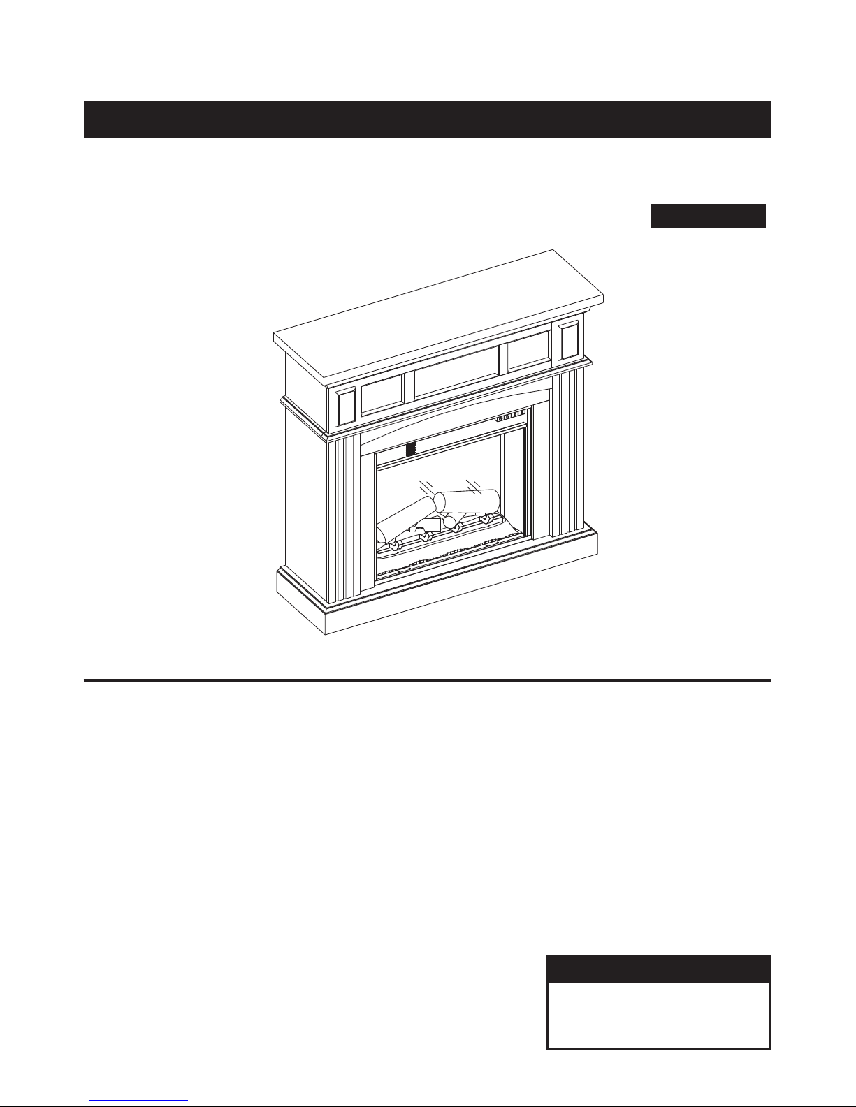
ELECTRIC FIREPLACE
73702/23WM9083-PM92
INSTRUCTION MANUAL
Español p.15
TABLE OF CONTENTS
Important Information....................................................................................................................... 2
Product Specifi cations..................................................................................................................... 3
Package Contents........................................................................................................................... 4
Hardware Contents.......................................................................................................................... 5
Safety Information............................................................................................................................. 5
Preparation....................................................................................................................................... 6
Assembly Instruction........................................................................................................................ 6
Operating Instructions...................................................................................................................... 9
Care and Maintenance..................................................................................................................... 1 1
Troubleshooting............................................................................................................................... 12
Warranty.......................................................................................................................................... 13
Replacement Parts List.................................................................................................................. 14
For Customer Service:
Twin-Star International, Inc.
Delray Beach, FL 33445
Made in China
Printed in China
E-mail: parts@twinstarhome.com
In English call: 866-661-1218
In French call: 866-374-9203
In Spanish call: 866-661-1218
1

IMPORTANT INFORMATION
Please read and understand this entire manual before attempting to assemble, operate or install
the product. If you have any question regarding the product, please call customer service at
1-866-661-1218, 8 a.m.-8 p.m., EST, Monday-Friday.
When using electrical appliances, always follow basic precautions to reduce the risk of fi re,
electrical shock, and injury to persons including the following:
1. Read all instructions before using this appliance.
2. This appliance is hot when in use. To avoid burns, do not touch hot surfaces with bare skin.
If provided, use handles when moving this appliance. Keep combustible materials, such as furniture,
pillows, bedding, papers, clothes and curtains at least 3 ft. (0.9 m) from the front of this appliance.
WARNING: In order to avoid overheating, do not cover the heater.
WARNING: Use extreme caution when operating heater near children and the disabled.
3. The appliance is not to be used by children or persons with reduced physical, sensory or mental
capabilities, or lack of experience and knowledge, unless they have been given supervision
or instruction.
4. This appliance is not a toy. Supervise children playing near it.
5. If possible, always unplug this appliance when not in use.
6. Do not operate any heater with a damaged cord or plug, after the appliance malfunctions, or if it has
been dropped or damaged in any manner.
7. If the supply cord is damaged, it must be replaced by the manufacturer, its service agent or similarly
qualifi ed persons in order to avoid a hazard.
8. Only a qualifi ed service person should repair this product.
9. Under no circumstances should this fi replace be modifi ed. Parts having to be removed for servicing
must be replaced prior to operating this fi replace again.
10. Do not use outdoors.
11. This heater is not intended for use in bathrooms, laundry areas and similar indoor locations. Never
locate this appliance where it may fall into a bathtub or other water container.
12. Do not run cord under carpeting. Do not cover cord with throw rugs, runners or the like. Arrange cord
away from traffi c areas and where it will not be tripped over.
13. To disconnect this appliance, turn controls to the off position, and then remove plug from outlet.
14. Connect to properly grounded outlets only.
15. This appliance, when installed, must be electrically grounded in accordance with local codes or, in
the absence of local codes, with the current CSA C22.1 Canadian Electrical Code or for U.S.A.
installations, follow local codes and the National Electrical Code, ANSI/NFPA NO.70.
16. The heater must not be located immediately below a socket-outlet.
17. Do not insert or allow foreign objects to enter any ventilation or exhaust opening as this may cause
an electric shock or fi re, or damage the appliance.
18. To prevent a possible fi re, do not block air intakes or exhaust in any manner. Do not use on soft
surfaces, like a bed, where opening may become blocked.
19. This appliance has hot and arcing or sparking parts inside. Do not use it in areas where gasoline,
paint or fl ammable liquids are used or stored. This fi replace should not be used as a drying rack for
clothing. Do not hang Christmas stockings or other decorations on or near this product.
20. Use this appliance only as described in the manual. Any other use not recommended by the
manufacturer may cause fi re, electric shock or injury to persons.
21. There is a thermostat limiter inside the heater. When inner temperature overheating or abnormal
heating occurs, the thermostat protective device will cutoff the power supply to avoid damage to the
fi replace or risk of fi re.
2
IMPORTANT INFORMATION
22. Avoid the use of an extension cord because the extension cord may overheat and cause risk of fi re.
However, if you have to use an extension cord, the cord must be No.14 AWG minimum size and rated
not less than 1875 watts. The extension cord must be a three-wire cord with grounding type plug and
cord connection. The extension cord shall not be more than 20 ft. (6 m) in length.
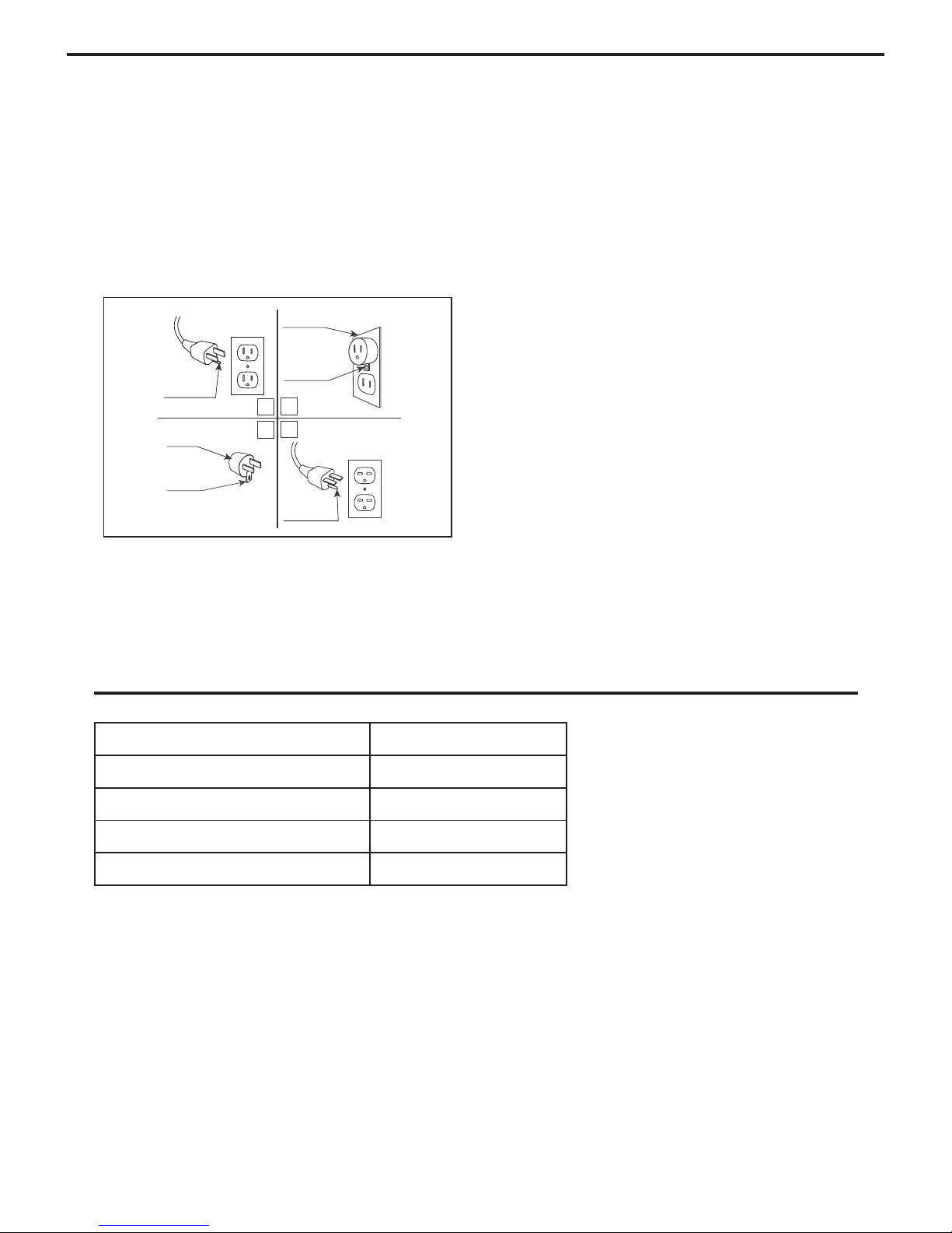
23. See directions in Figure 1. This heater is for use on 120 volts. The cord has a plug as shown in
figure 1. See Figure 1 for grounding instruction. An adapter as shown at C is available for
connecting three-blade grounding type plugs to two-slot receptacles. The green grounding plug
extending from the adapter must be connected to a permanet ground such as a properly
gounnded outlet box. The adapter should not be used if a three-slot grounded receptacle is
available.
Metal
Screws
Grounding Pin
B
A
D
C
SAVE THESE
Grounding
Means
Fig. 1
PRODUCT SPECIFICATIONS
VOLTAGE 120 V, 60 Hz
AMPS (with heater) 11.7 Amps
AMPS (without heater) < 0.1 Amps
WATTS (with heater) 1400 Watts
WATTS (without heater) < 10 Watts
INSTRUCTIONS
3
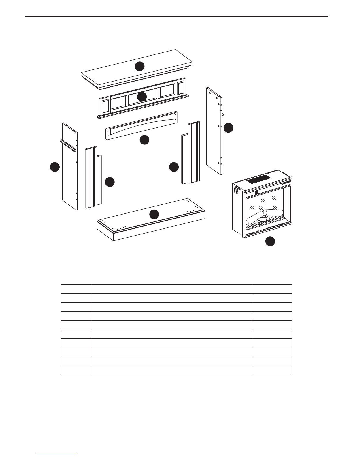
PACKAGE CONTENTS
E C
G
H
F
D
B
A
I
Part Description Quantity
A Hearth/Base 1
B Left Front Panel 1
C Right Front Panel 1
D Center Front Panel 1
E Left Side Panel 1
F Right Side Panel 1
G Mantel/Top 1
H Center T op Panel 1
I Insert 1
4
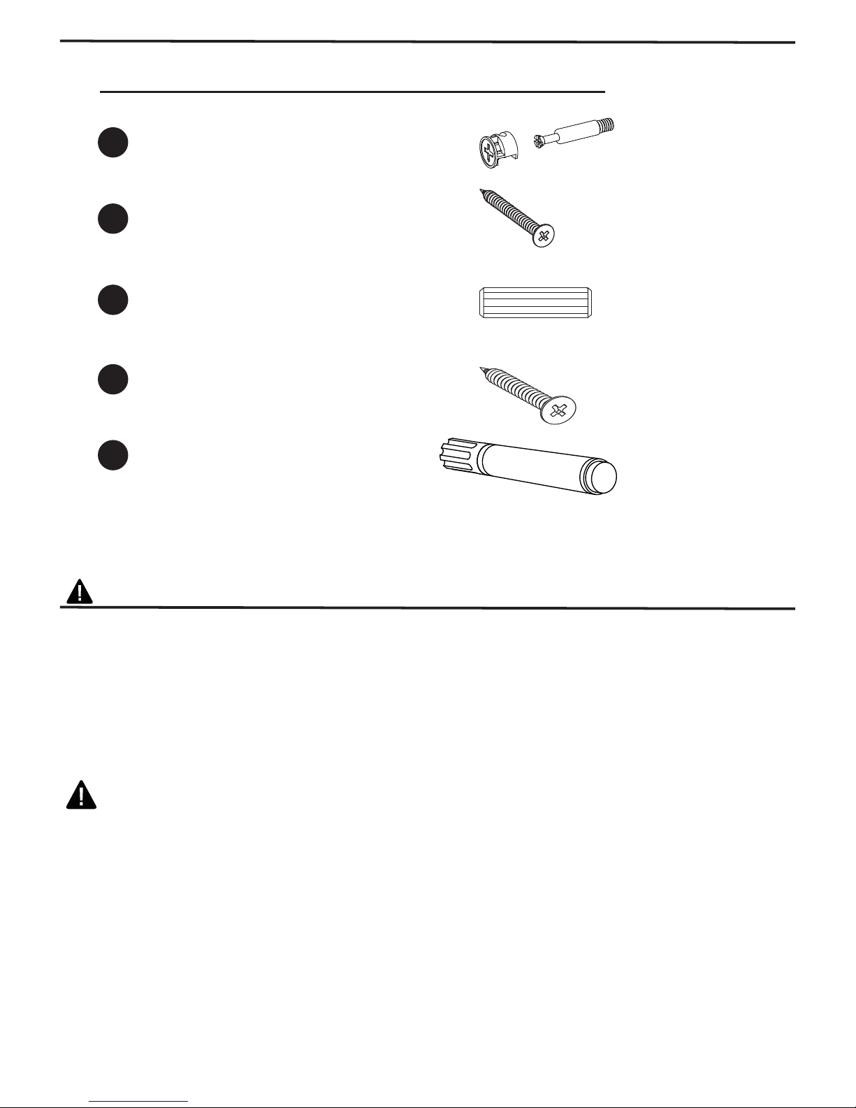
HARDWARE CONTENTS
Part
Description Quantity
Picture
(Shown to size)
AA
BB
CC
DD
ZZ
Camlock
Screw
Wood Dowel
Screw
Touch-up Pen
Model No. W3348
16
8
24
4
1
W3348
SAFETY INFORMATION
WARNING
• Before assembly, carefully use scissors or utility knife to cut and unwrap all parts.
Make sure you do not discard the hardware.
CAUTION
• Use care in assembling your new fireplace. Take your time and use the hardware
provided and a quality Phillips head screwdriver. Never overtighten bolts.
• Do not sit on any part of the mantel.
• All panels are labeled left and right as viewed from the front of unit.
WARNING
To avoid injury from unexpected starting or electrical shock, do not plug the power cord into a
source of power during unpacking and assembly. The cord must remain unplugged whenever
you are adjusting/assembling the fi replace.
If any part is missing or damaged, do not attempt to use or plug in the power cord until the
missing or damaged part is correctly replaced. To avoid electric shock, use only identical
replacement parts when servicing double-insulated tools.
5
PREPARATION
Before beginning assembly of product, make sure all parts are present. Compare parts
with package contents list and diagram above. If any part is missing or damaged, do not
attempt to assemble, install or operate the product. Contact customer service for
replacement parts.
Estimated Assembly Time: 60 Minutes
Tools Required for Assembly (not included): Phillips head screwdriver, scissors
and utility knife
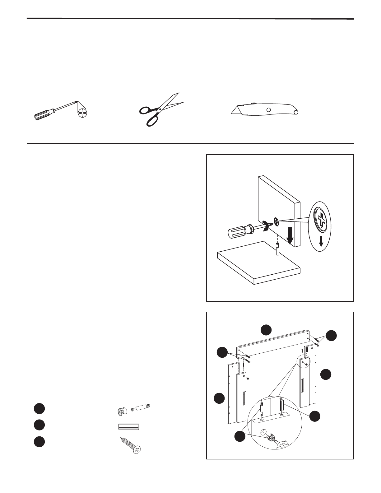
ASSEMBLY INSTRUCTIONS
Camlock installation.
For correct installation, screw AA-1 must be
inserted and tightened in the pre-drilled hole.
Camlock AA-2 must be inserted into the
pre-drilled hole with the cross positioned in
the direction of screw AA-1.
1. Locate the Left Front Panel (B), Right Front Panel
(C), Center Front Panel (D) and set out face down
on a scratch-free surface.
Insert one Wood Dowel (CC) and screw Camlock
(AA-1) into the holes of the Center Front Panel (D).
make sure to tighten Camlock (AA-1). Push Left
Front Panel (B) and Right Front Panel (C) snug to
the Center Front Panel (D). Insert Camlock
(AA-2) into the holes in the left and right side panels.
Insert one Screw (DD) into the pre-drilled holes on
the Center Front Panel (D). Use Phillips head
screwdriver to tighten Camlock (AA-2) and Screw
(DD).
Hardware Used
AA
CC
DD
Camlock x 2
Wood Dowel
x 2
Screw x 4
Fig. 1
D
DD
DD
B
C
CC
AA
6
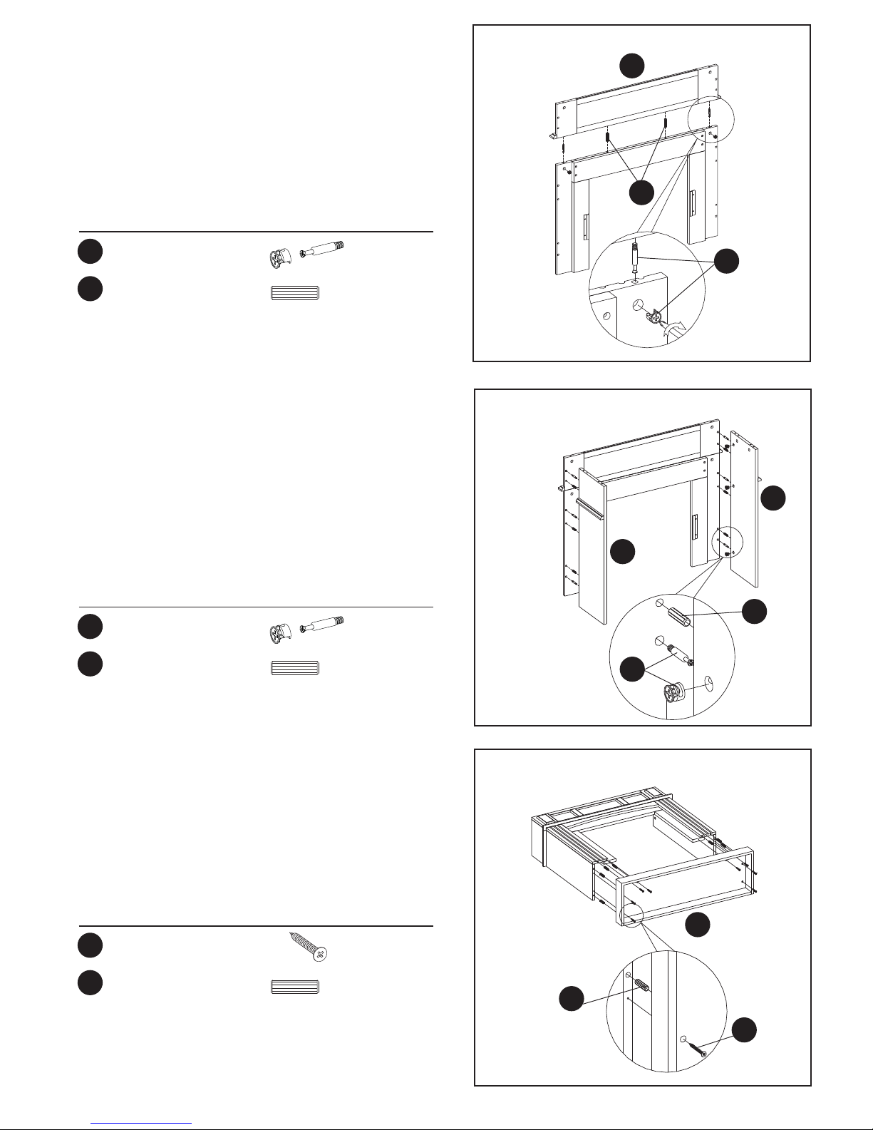
2. Screw Camlock (AA-1) into the holes in the
pre-drilled holes on the Center Top Panel (H), and
insert one Wood Dowel (CC) into the holes in the
pre-drilled holes on the top edge of the front
assembly, then attach Center Top Panel (H). Insert
Camlock (AA-2) into the holes in the left and right
side panels. Use Phillips head screwdriver to tighten
Camlock (AA-2).
HAND TIGHTEN ONLY.
Hardware Used
Fig. 2
H
CC
AA
CC
Camlock x 2
Wood Dowel
x 2
3.Screw Camlock (AA-1) into the holes in the
pre-drilled holes on the completed assembly from
the step 2, insert one Wood Dowel (CC) into the
holes on the side panels. make sure to tighten
Camlock (AA-1). Push Left Side Panel (E) and
Right Side Panel (F) snug to the Completed
assembly from the step 2. Insert Camlock (AA-2)
into the holes in the side panels. Use Phillips head
screwdriver to tighten Camlock (AA-2).
Hardware Used
AA
CC
Camlock x 6
Wood Dowel
x 6
AA
Fig. 3
E
F
CC
AA
4. Locate Hearth/Base (A) and lie down on scratch free
surface, Insert Wood Dowel (CC) into the
Hearth/Base, push the completed assembly from
the step 3 to the Hearth/Base as show in diagram,
tighten Screw (BB) through the pre-drilled holes.
Hardware Used
BB
CC
Screw
Wood Dowel
Fig. 4
A
x 8
x 8
CC
BB
7
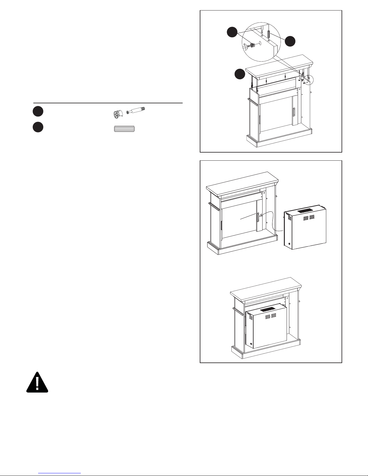
5. Insert one Wood Dowel (CC) into the pre-drilled
holes on the top edges of the assembly from step
4. Insert Camlock (AA-1) into the predrilled holes
in the underside of the Mantel/Top (G), make sure
to tighten. Insert Camlock (AA-2) into the holes in
the Side Panels. Attach the Mantel/Top (G) fi nished
side up to the completed assembly. Use Phillips
head screwdriver to tighten Camlock (AA-2).
Hardware Used
Fig. 5
AA
CC
G
AA
CC
Camlock x 6
Wood Dowel
x 6
6. Remove the two mounting brackets attached to the
back of the Left and Right Front panels.
Set aside with the wood screws.
PLEASE READ ALL “ELECTRIC FIREPLACE
INSERT” INSTRUCTIONS PRIOR TO INSTALLING
ELECTRIC INSERT IN YOUR COMPLETED
FIREPLACE MANTEL. INSTALL THE INSERT IN
YOUR FIREPLACE
Lift insert carefully into the back of the unit and
center in the insert opening. Do not drag insert
across Hearth/Base (A) as it may scratch your unit.
Install the mounting brackets to hold insert fl ush
against the inside of the mantel front panel.
MOVE YOUR COMPLETED UNIT ONLY SHORT
DISTANCES. MOVE COMPLETED UNIT WITH
GREAT CARE. IT TAKES TWO PEOPLE TO
MOVE COMPLETED UNIT INTO ITS FINAL
POSITION.
Fig. 6
Install
Insert
From
Back
Mounting
Bracket
Electric
Fireplace Insert
Completed
Unit
Cold climate installation recommendation: When installing this unit against a noninsulated exterior wall or chase, it is mandatory that the outer walls be insulated to
conform to applicable insulation codes.
ELECTRICAL CONNECTION
A 15-Amp, 120-V, 60 Hz circuit with a properly grounded outlet is required. Preferably, the fi replace will
be on a dedicated circuit as other appliances on the same circuit may cause the circuit breaker to trip or
the fuse to blow when the heater is in operation. The unit comes standard with 6-ft. three-wire
cord, exiting from the rear of the fi replace. Avoid using an extension cord. If an extension cord must be
used, it must be a minimum 14 AWG, three wire with grounding type plug connector and rated not less
than 1875 watts. The cord shall not be more than 20 ft. in length.
8
 Loading...