

Twin-Star International 36II100GRG, 47II100GRG User Manual
www.tsicustomerservice.comA189
1
Twin-Star International, Inc; Delray Beach, FL 33445
Made in China • Printed in China • Fabricado en China • Impreso en China • Fabriqué en China • Imprimé en Chine
www.tsicustomerservice.com
1-866-661-1218
MODELS/ MODÈLES:
36II100GRG, 47II100GRG
Français: P.29

2
www.tsicustomerservice.comA189
Table of Contents
Important Instructions .................................................... 3
Warranty ........................................................................ 4
Getting Started .............................................................. 5
Pre-Assembly ................................................................ 6
Hardware Included ............................................... 6
Product Specifications ............................................. 6
Tools Required ........................................................ 6
Package Contents ................................................... 7
Installation Options ........................................................ 8
Wall Hanging .......................................................... 9
Pedestal Base ...................................................... 12
Built In Construction ............................................. 14
Assembly with mantel ........................................... 18
Fuel Bed Setup Instructions ................................. 21
Operation ..................................................................... 23
FCC/IC Information...................................................... 26
Care & Cleaning .......................................................... 26
Troubleshooting ........................................................... 27
Replacement Parts ...................................................... 28
3
www.tsicustomerservice.comA189
SAVE THESE INSTRUCTIONS
When using electrical appliances, basic precautions should always be followed to reduce the risk of re, electrical shock, and injury to
persons including the following:
1. Read all instructions before using this appliance.
2. This appliance is hot when in use. To avoid burns, do not let bare skin touch hot surfaces. If provided, use handles when moving
this appliance. Keep combustible materials, such as furniture, pillows, bedding, papers, clothes and curtains at least 3 feet (0.9 m)
from the front of this appliance and keep away from the sides and the rear. WARNING: In order to avoid overheating,
do not cover the heater.
3. CAUTION: Never leave the heater operating unattended. Extreme caution is necessary if unsupervised children or invalids are
nearby.
4. The appliance is not to be used by children or persons with reduced physical, sensory or mental capabilities, or lack of experience
and knowledge, unless they have been given supervision or instruction.
5. Always unplug this appliance when not in use.
6. Do not operate any heater with a damaged cord or plug or after the appliance malfunctions, or if it has been dropped or damaged
in any manner.
7. If the supply cord is damaged, it must be replaced by the manufacturer, its service agent or similarly qualied persons in order to
avoid a hazard.
8. Do not use outdoors.
9. This heater is not intended for use in bathrooms, laundry areas and similar indoor locations. Never locate this appliance where it
may fall into a bathtub or other water container.
10. Do not run cord under carpeting. Do not cover cord with throw rugs, runners or the like. Arrange cord away from trafc areas and
where it will not be tripped over.
11. To disconnect this appliance, turn controls to the off position, then remove plug from outlet.
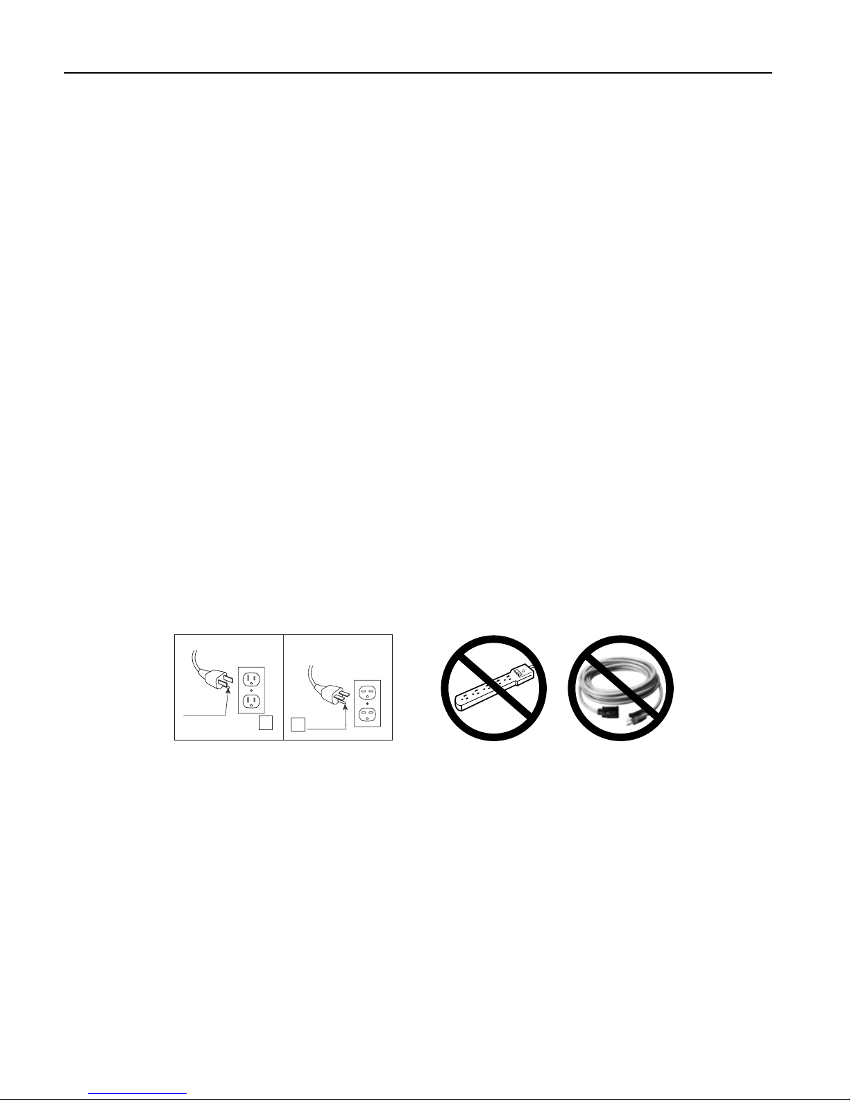
12. Connect to properly grounded outlets only. This heater is for use on 120 volts. The cord has a plug as shown at A in Fig.1 Do not
use a 2 prong adapters. Never use with an extension cord or relocatable power tap (outlet/power strip).
13. This appliance, when installed, must be electrically grounded in accordance with local codes or, in the absence of local codes, with
the current CSA C22.1 Canadian Electrical Code or for U.S.A. installations, follow local codes and the National Electrical Code,
ANSI/NFPA NO.70.
14. Do not insert or allow foreign objects to enter any ventilation or exhaust opening as this may cause an electric shock or re, or
damage the appliance.
15. To prevent a possible re, do not block air intakes or exhaust in any manner. Do not use on soft surfaces, like a bed, where opening
may become blocked.
16. This appliance has hot and arcing or sparking parts inside. Do not use it in areas where gasoline, paint or ammable liquids are
used or stored. This replace should not be used as a drying rack for clothing. Christmas stockings or decorations should not be
hung in the area of it.
17. Use this appliance only as described in the manual. Any other use not recommended by the manufacturer may cause re, electric
shock or injury to persons.
A
B
Fig.1
IMPORTANT INSTRUCTIONS

4
www.tsicustomerservice.comA189
The manufacturer warrants that your new Electric Fireplace is free from manufacturing and material defects for a period
of one year from date of purchase, subject to the following conditions and limitations.
1. Install and operate this appliance in accordance with the installation and operating instructions furnished with the
product at all times. Any unauthorized repair, alteration, willful abuse, accident, or misuse of the product shall nullify
this warranty.
2. This warranty is non-transferable, and is made to the original owner, provided that the purchase was made through
an authorized supplier of the product.
3. The warranty is limited to the repair or replacement of part(s) found to be defective in material or workmanship,
provided that such part(s) have been subjected to normal conditions of use and service, after said defect is conrmed
by the manufacturer’s inspection.
4. The manufacturer may, at its discretion, fully discharge all obligations with respect to this warranty by refunding
the wholesale price of the defective part(s).
5. Any installation, labor, construction, transportation, or other related costs/expenses arising from defective part(s),
repair, replacement, or othe wise of same, will not be covered by this warranty, nor shall the manufacturer assume
responsibility for same.
6. The owner/user assumes all other risks, if any, including the risk of any direct, indirect or consequential loss or
damage arising out of the use, or inability to use the product,except as provided by law.
7. All other warranties – expressed or implied –with respect to the product, its components and accessories, or any
obligations/liabilities on the part of the manufacturer are hereby expressly excluded.
8. The manufacturer neither assumes, nor authorizes any third party to assume on its behalf, any other liabilities with
respect to the sale of the product.
9. The warranties as outlined within this document do not apply to non accessories used in conjunction with the
installation of this product.
10. This warranty gives you specic legal rights, and you may also have other rights which vary from state to state.
This warranty is void if:
a. The replace is subjected to prolonged periods of dampness or condensation.
b. Any unauthorized alteration, willful abuse, accident, or misuse of the product.
c. You do not have the original receipt of purchase.
www.tsicustomerservice.com
For Customer Service Call 1-866-661-1218
Questions? Our experts are standing by assist you at our Toll-Free help line, we can help you with assembly,
and, if necessary replace damaged/missing parts. Assistance is available 7 days a week/24 hours a day/
365 days per year.
IMPORTANT:
Before contacting Customer Service please have this information available:
•SerialNumber
•ModelNumber
•SalesReceiptorProofofPurchase
1-Year Limited Warranty
Customer Service
5
www.tsicustomerservice.comA189
M
a
n
e
g
M
o
d
e
l
/
M
o
d
è
l
e
/
M
o
d
e
l
o
:
4
7
H
F
1
0
0
G
R
G
S
N
#
:
A
B
-
1
2
3
4
5
-
A
K
e
e
p
t
h
i
s
n
u
m
b
e
r
f
o
r
s
e
r
v
i
c
e
!
G
a
r
d
e
z
c
e
n
u
m
é
r
o
p
o
u
r
l
e
s
e
r
v
i
c
e
!
t
a
e
s
t
e
n
ú
m
e
r
o
p
a
r
a
s
e
r
v
i
c
i
o
!
Getting Started
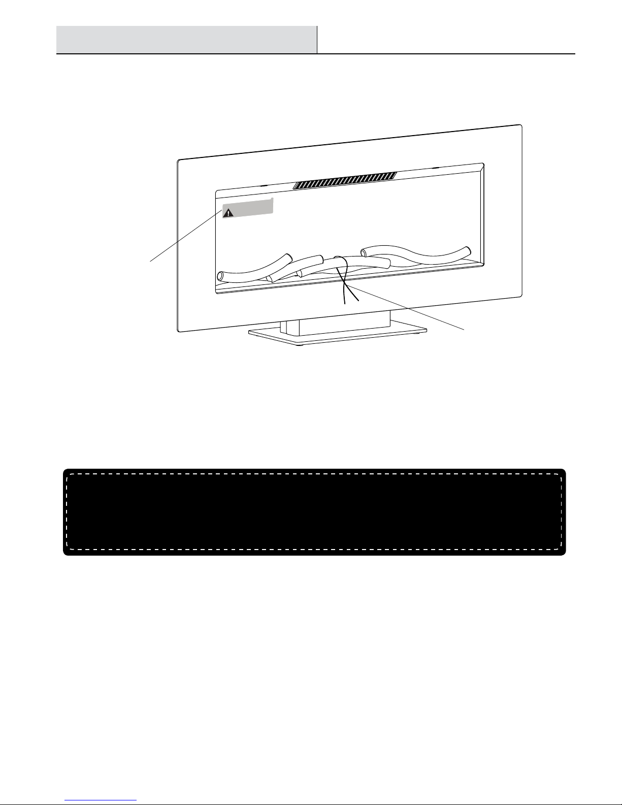
1. Remove the product identication sticker from the front of the replace and the twist-tie from the logset.
Product
Identication
Sticker
2. Attach the Product Identication Sticker to this Manual below for future reference. This information is used for product registration and
also is necessary for customer service.
3. Go to www.tsicustomerservice.com for product warranty registration. If you are unable to complete registration save your proof of
purchase for warranty purposes.
Attach Product Identication Sticker Here
Twist-tie
6
www.tsicustomerservice.comA189
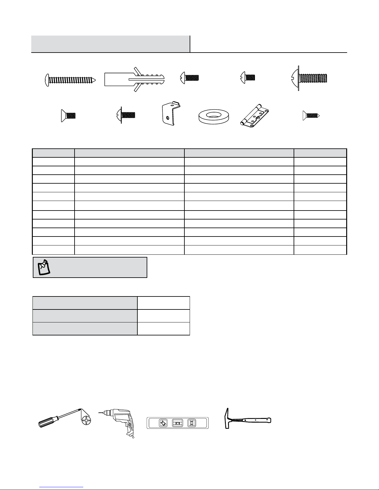
Part Description Part Number Quantity
AA Anchor Screw 3647HF-AA 4
BB Wall Anchor 3647HF-BB 4
CC Screw 4mm x 8mm (2 Pre-Attached) 3647HF-CC 4
DD Screw 4mm x 6mm (3 Pre-Attached) 3647HF-DD 8
EE Screw 3647HF-EE 7
FF Flat Head Screw 3647HF-FF 2
GG Screw (Pre-Attached) 3647HF-GG 2
II Small Base Bracket 3647HF-II 1
JJ Washer 3647HF-JJ 4
KK Mounting Hinge 3647HF-KK 4
LL Screw 3647HF-LL 8
Pre-Assembly
HARDWARE INCLUDED
AA
DD
BB
CC
EE
FF
GG
NOTE:
Hardware not shown to actual size.
PLANNING ASSEMBLY
Before beginning assembly of product, make sure all parts are present. Compare parts with Hardware Included and Package Contents lists.
If any part is missing or damaged, do not attempt to assemble, install or operate the product. Contact customer service for replacement
parts.
Estimated Assembly Time: 60 Minutes
Phillips Screwdriver
PRODUCT SPECIFICATIONS
Voltage 120 VAC, 60 Hz
Amps 12.5 Amps
Watts 1500 Watts
JJ
II
Tools Required for Assembly (not included): Phillips screwdriver, Drill, Hammer, Level
LevelDrill Hammer
KK LL

7
www.tsicustomerservice.comA189
Part Description Quantity
A Mounting Bracket (Pre-Attached) 1
B Fireplace 1
C Front Frame 1
D Base Bracket 1
E
Base
1
F Remote Control 1
G Decorative Rocks Varies
H Transparent Tray Assembly 1
I Fireglass Varies
PACKAGE CONTENTS
Pre-Assembly (continued)
A
B
C
D E
F
G
H
I
8
www.tsicustomerservice.comA189
Operation
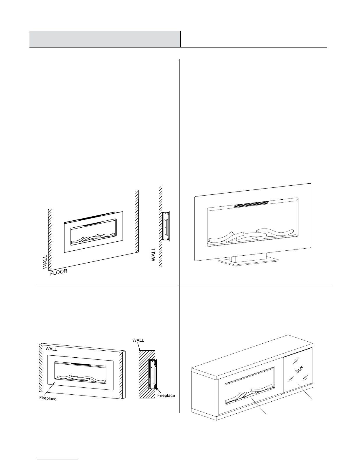
Installation Options
Option 1
Option 3
Option 2
Wall Hanging....page 9
Built in construction....page 14
Pedestal Base....page 12
The replace can be installed with
4 options:
1. Wall hanging with provided mounting bracket.
2. Free standing with provided pedestal base.
3. Built in construction.
4. Assembly with mantel.
Follow installation instructions below based on installation
preference.
Option 4
Assembly with mantel....page 18
Fireplace
Mantel
9
www.tsicustomerservice.comA189
Operation
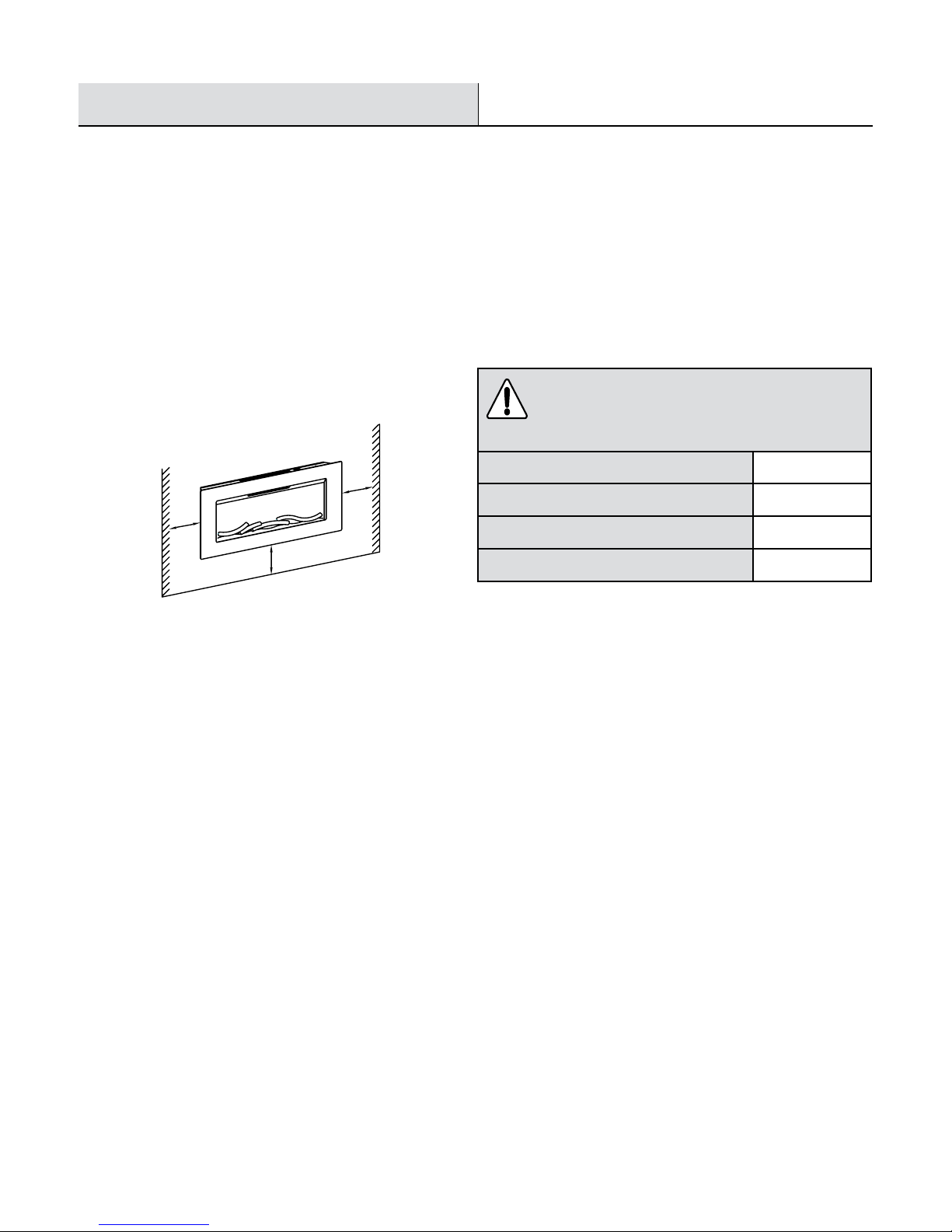
Installation - Wall Hanging
WALL HANGING TO THE WALL WITH PROVIDED MOUNTING BRACKET
Your new electric replace may be installed virtually anywhere in your home. However, when choosing a location be sure to follow the
general instructions included. For best results install out of direct sunlight. Power supply service must be either completed or placed within
the electric replace prior to nishing to avoid reconstruction.
Sides 2 in. / 5 cm
Floor 2 in. / 5 cm
Top 2 in. / 5 cm
Back 0 in. / 0 cm
WARNING:
Keep drapery and other furnishings at least 3 ft / 1 m
from the front and sides of the electric replace.
Clearance to combustibles
Min. 5 cm
2 in.
Min. 5 cm
2 in.
Min. 5 cm
2 in.
10
www.tsicustomerservice.comA189
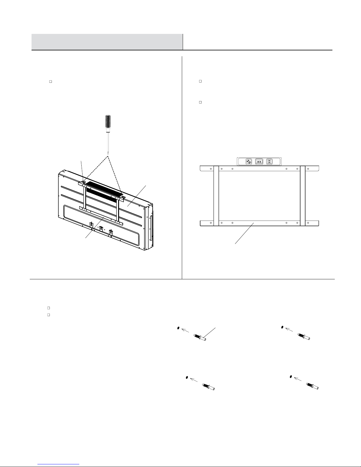
Operation
Installation - Wall Hanging
3
Drilling the Holes
1
Removing the Mounting Bracket
2
Choosing a Wall Location
Remove the Mounting Bracket (A) from the back of the
Fireplace (B) by removing the two pre-attached Screws
(CC) at the top back of the unit.
Choose a wall location to attach the Mounting
Bracket (A). Position the Mounting Bracket (A)
in the desired location.
Use a level to align the bracket and mark the four holes
with a pencil.
Drill four 5/16 in. (8 mm) holes in the wall.
Insert the Wall Anchors (BB) into the holes using
a hammer.
BB
B
A
A
CC
11
www.tsicustomerservice.comA189
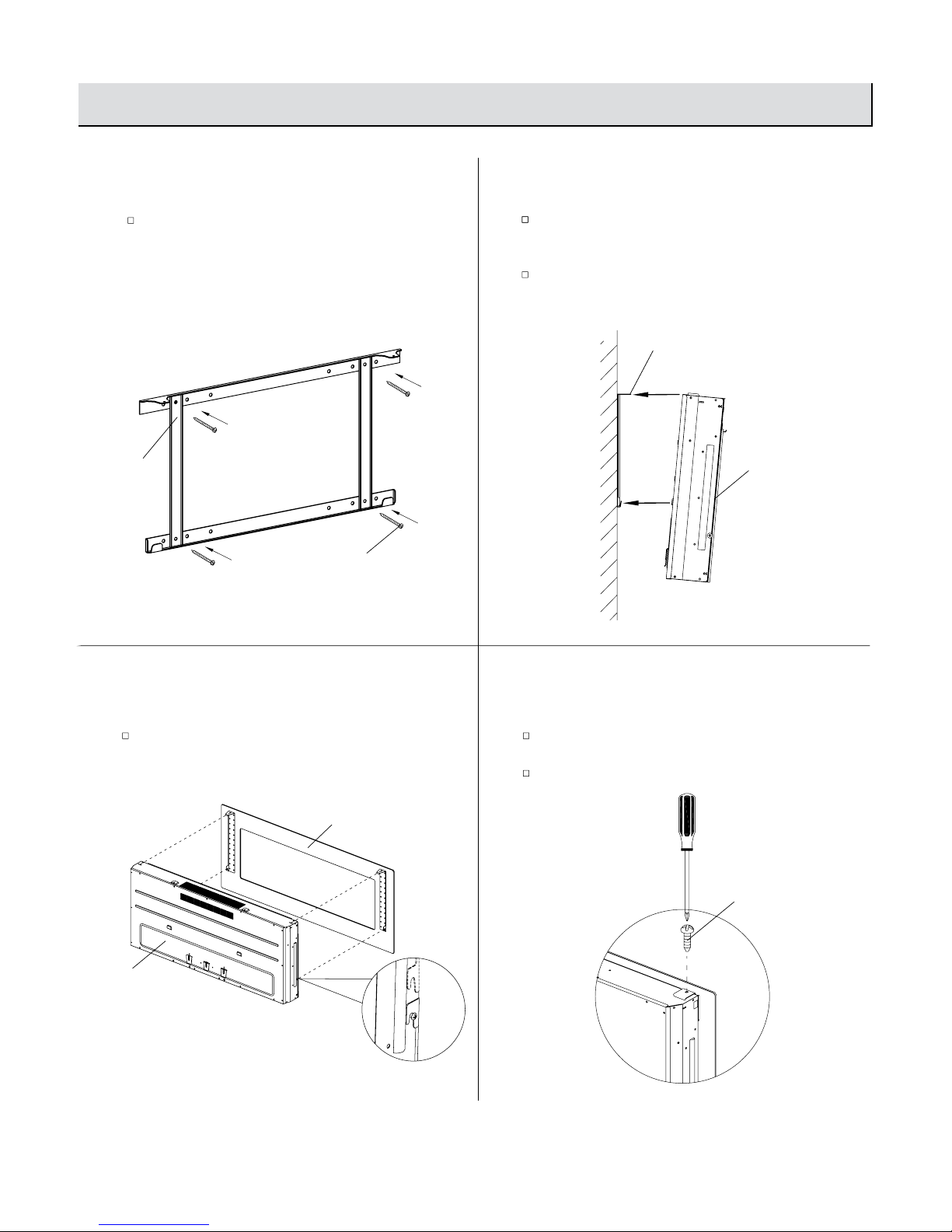
Operation
6
Hanging the Front Frame
4
Attaching the Mounting Bracket
5
Hanging the Fireplace
Attach the Mounting Bracket (A) to the wall by fastening
the four Anchor Screws (AA) into the wall anchors.
Hang the Fireplace (B) on the hooks at the bottom of
the Mounting Bracket (A) and push the Fireplace (B)
into the Mounting Bracket (A).
Re-fasten the two screws removed in Step 1.
Hang the Front Frame (C) on the Fireplace (B) and gently
push on the lower part of the frame until it snaps into
place.
7
Securing the Front Frame
Secure the top frame hooks with the two retaining
Screws (CC).
Continue to the fuel bed setup instructions (Page 21).
AA
B
A
CC
A
Operation
Installation - Wall Hanging (continued)
B
C
12
www.tsicustomerservice.comA189
Operation
Installation - Pedestal Base
3
Attaching the Base Bracket
1
Fastening the Base Bracket
2
Attaching the Small Base Bracket
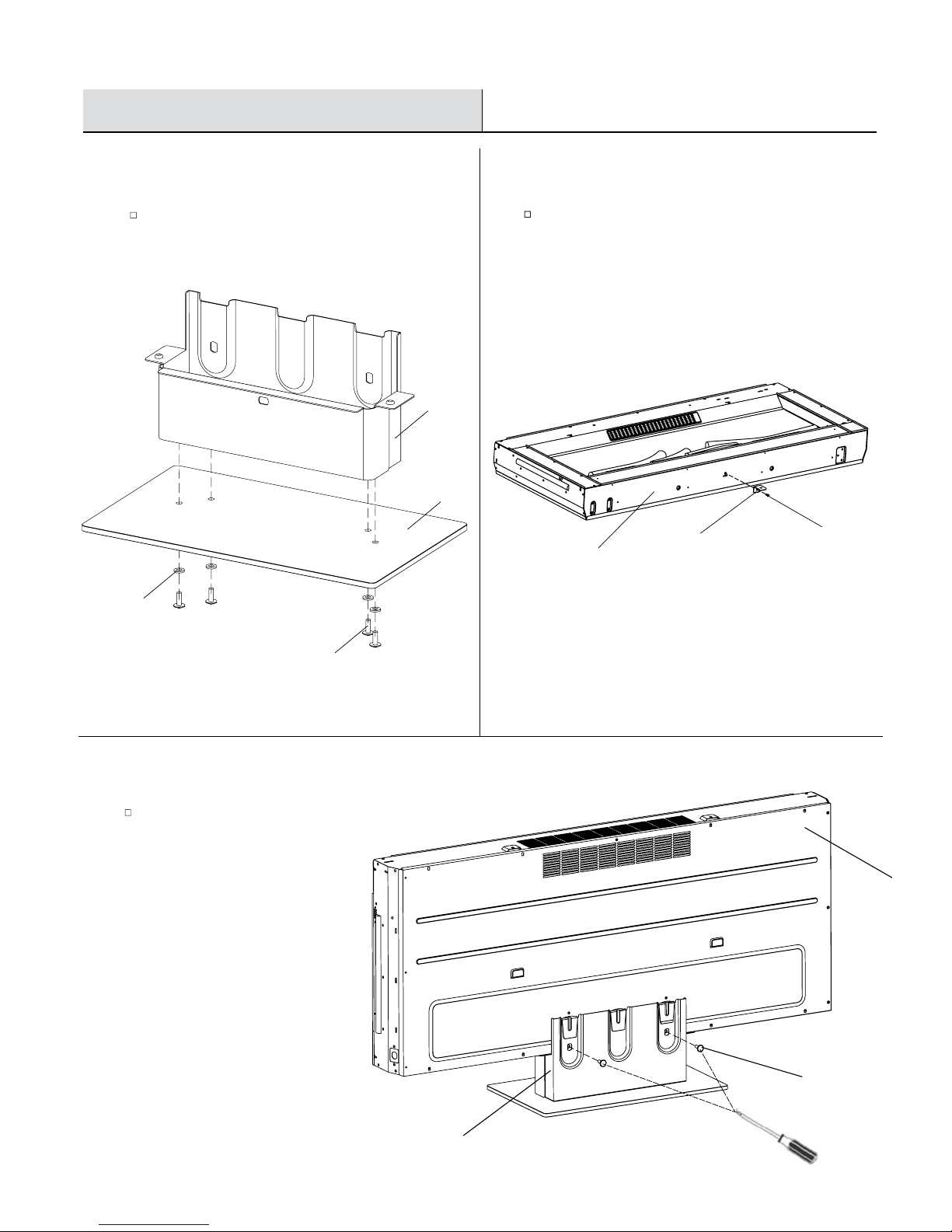
Use four Screws (EE) and four Washers (JJ) to fasten the
Base Bracket (D) to the Base (E).
Use one Screw (DD) to fasten the Small Base Bracket (II)
to the Fireplace (B).
Fasten the Base Bracket (D) to the Fireplace (B) with the
provided Screws (EE).
E
EE
D
II
B
DD
EE
D
B
JJ
13
www.tsicustomerservice.comA189
Operation
Installation - Pedestal Base
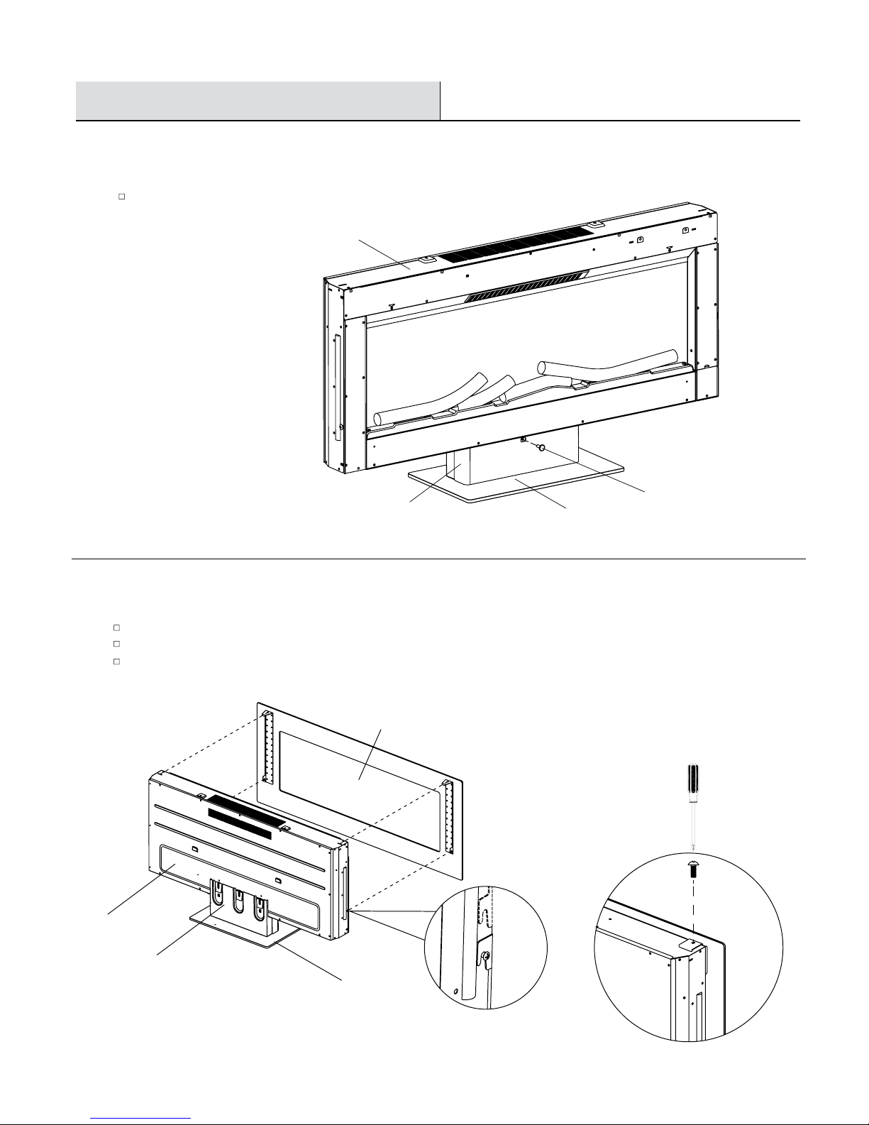
5
Secure the Top Frame
4
Fastening the Base Bracket
Use one Screw (EE) to fasten the Base Bracket (D) to the Fireplace (B).
Mount the Front Frame (C) to the Fireplace (B) by hooking the clips into position.
Tighten the two Screws (CC).
Continue to the fuel bed setup instructions (Page 21).
EE
D E
B
C
B
E
D
14
www.tsicustomerservice.comA189
Operation
BUILT IN TO A WALL INSTRUCTIONS
This replace is a zero clearance design. No combustibles can be placed on the top surface of the replace.
Combustibles may be installed to the edge of the unit. Insulation and vapor barrier should be placed a minimum of 2 in. from the unit.
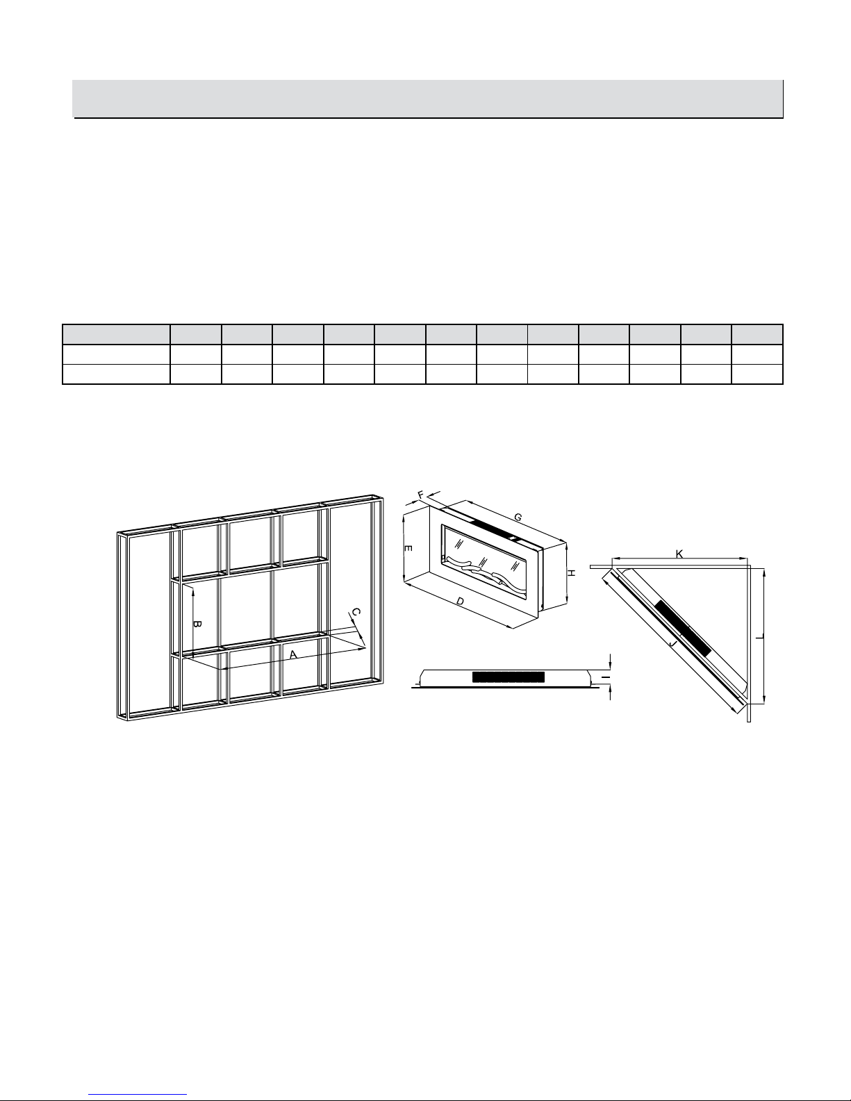
Build the framing according to the specications shown in the below table & gure 1.
Model A B C D E F G H I J K L
36II100GRG 32.8” 18.6” 3.9” 36” 19.7” 4.5” 31.8” 18” 3.5” 37.2” 26.3” 26.3”
47II100GRG 43.3” 18.6” 3.9” 46.2” 19.7” 4.5” 42.3” 18” 3.5” 47.5” 33.6” 33.6”
WIRING REQUIREMENTS
Use appropriate wire to meet local and national electrical codes for rated power consumption. All wire gauges should be 12 gauge solid
wires with a dedicated 15 amp breaker for 120 volts.
Fig. 1
Installation - Built In Construction
15
www.tsicustomerservice.comA189
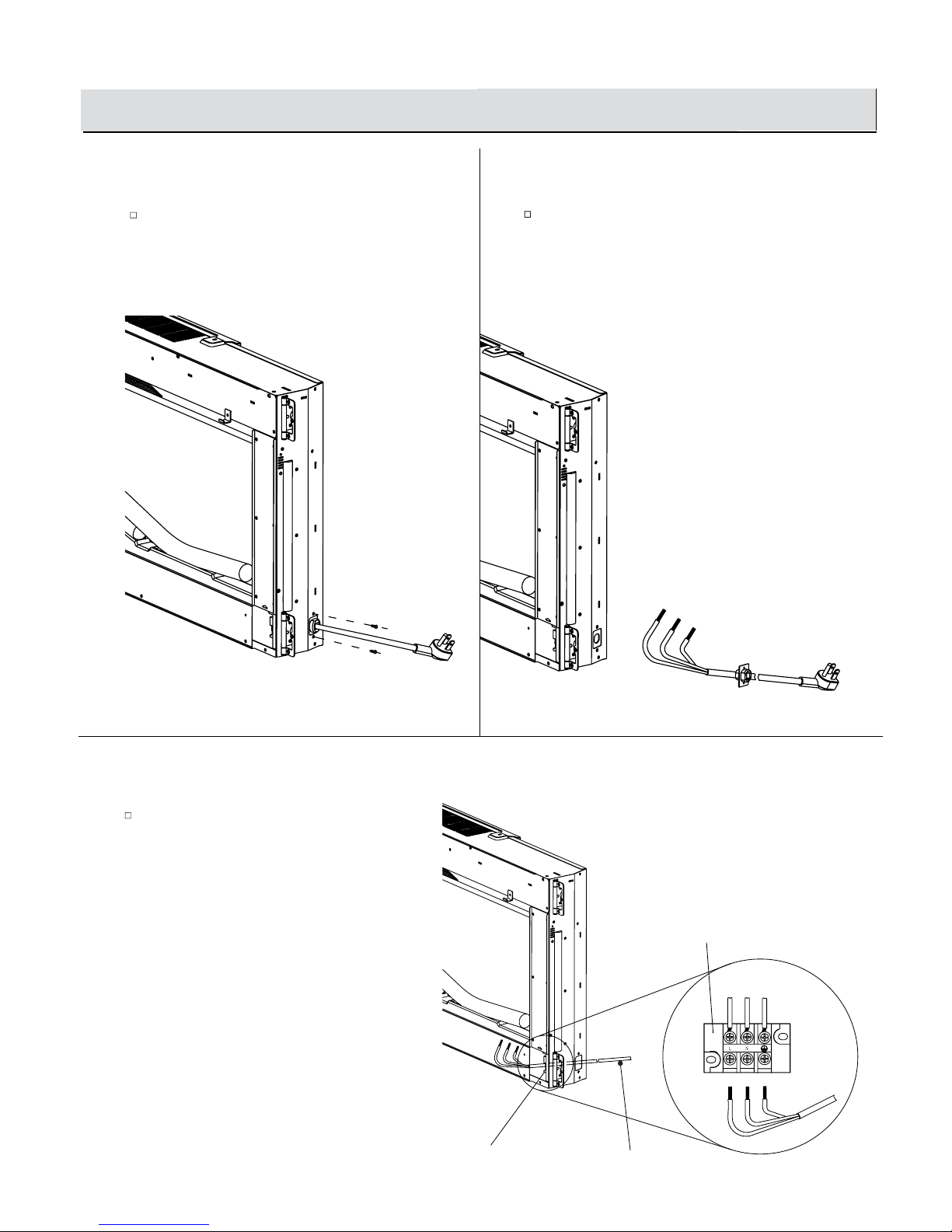
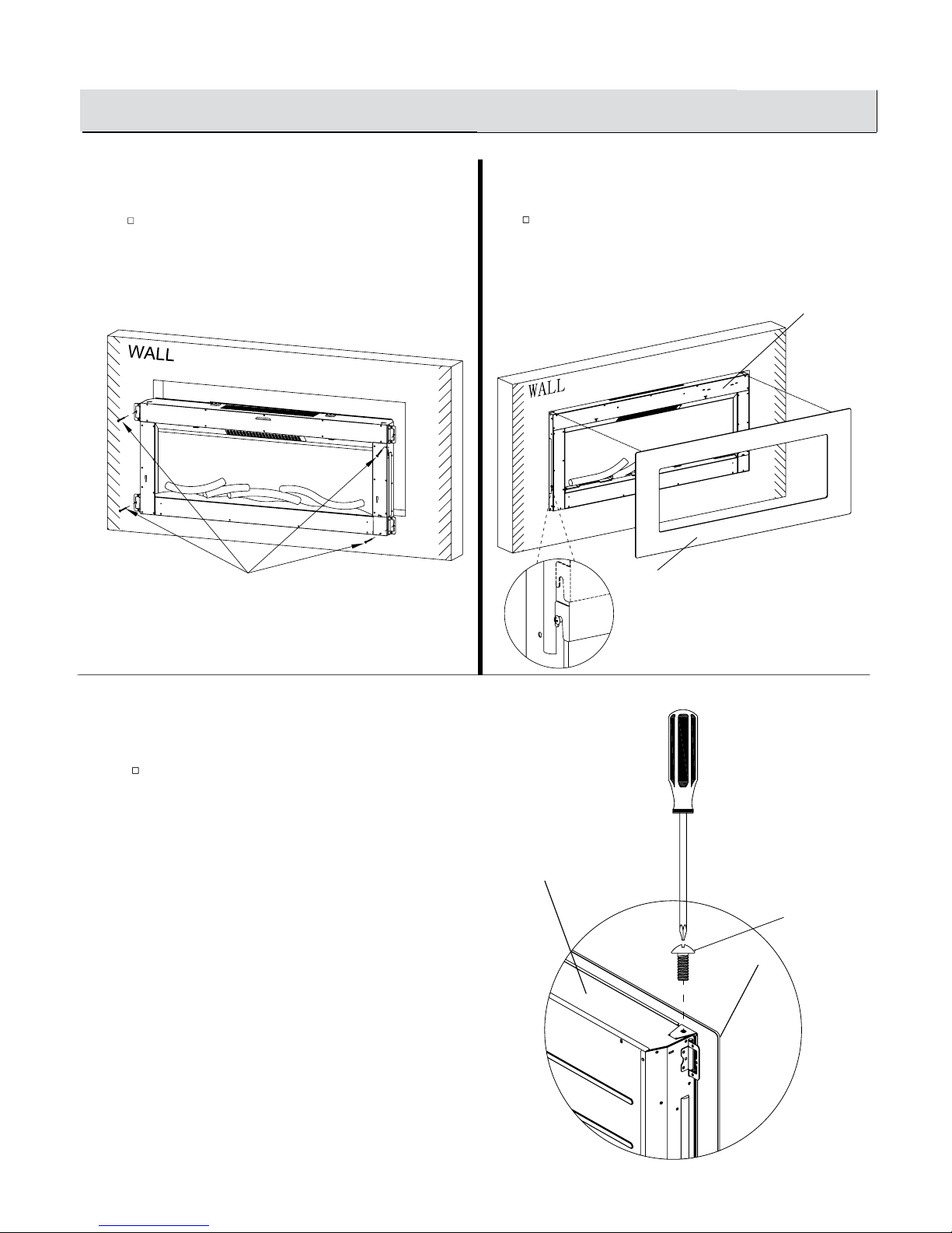
3
Steps 3 to 6 describe optional installation for
removing the power cord and changing to hard wired
1
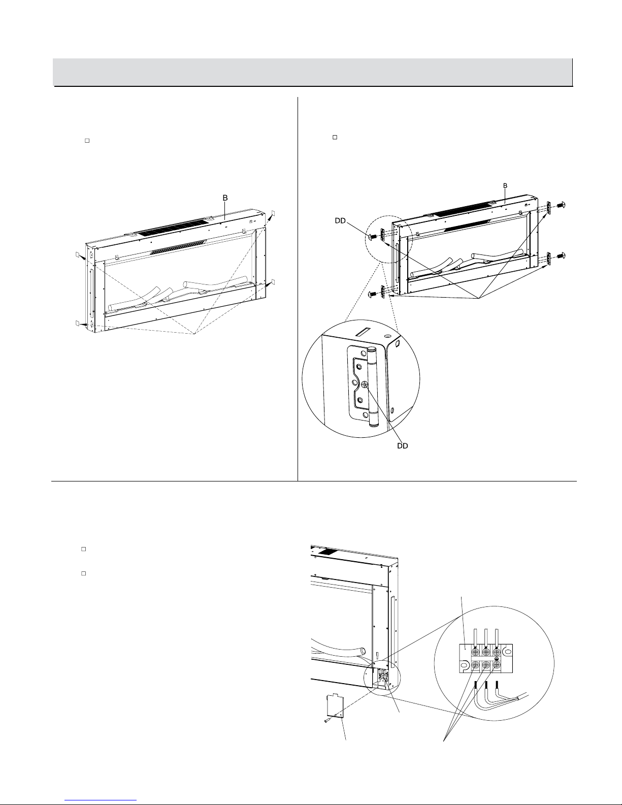
Removing the Stickers
2
Fastening the Hinges
Remove the black stickers.
Fasten the mounting hinges (KK) with Screws (DD).
Remove the pre-attached Screw (DD) holding
the junction box cover.
Loosen the three screws holding the wires and
remove the Negative, Live and Ground wires.
Operation
Junction Box Cover
Terminals
Terminals
Loosen the 3 screws
Black stickers
Installation - Built In Construction (continued)
L N G
KK
16
www.tsicustomerservice.comA189
6
Connecting the Power Supply Wire
4
Loosening the Strain Relief Bracket
5
Fastening the Brackets
Remove the two pre-attached Screws (DD) holding the
power cord strain relief bracket.
Remove the power cord and strain relief assembly.
Connect the power supply wire.
Strain Relief
Power Cord Assembly
Terminals
Power Supply Cord
Terminals
Operation
Installation - Built In Construction (continued)
L N G
17
www.tsicustomerservice.comA189
9
Securing the Top Frame Hooks
7
Installing the Fireplace
8
Hanging the Front Frame
Secure the replace to the wall using Anchor Screws (AA).
Hang the Front Frame (C) on the Fireplace (B) and gently
push on the lower part of the frame until it snaps into
place.
Operation
C
B
Secure the top frame hooks with the two retaining
Screws (CC).
Installation - Built In Construction (continued)
C
B
AA
CC
 Loading...