

Twin-Star International 18E05, 23E05, 33E05, 28E05 Operating Manual
CONSUMER SAFETY INFORMATION
PLEASE READ THIS MANUAL BEFORE INSTALLING
AND OPERATING THIS APPLIANCE
WARNING!!
IF THE INFORMATION IN THIS MANUAL IS NOT FOLLOWED EXACTLY,
AN ELECTRIC SHOCK OR FIRE MAY RESULT CAUSING PROPERTY
DAMAGE, PERSONAL INJURY OR LOSS OF LIFE.
DO NOT STORE OR USE GASOLINE OR OTHER FLAMMABLE VAPORS
AND LIQUIDS IN THE VICINITY OF THIS OR ANY OTHER APPLIANCE.
Twin-Star International, Inc.
Delray Beach, FL 33483
In USA: 866-661-1218
In Canada: 866-374-9203
ELECTRIC FIREPLACE INSERT
HOMEOWNERS OPERATING MANUAL
ELECTRIC FIREPLACE INSERTS
MODELS 18E05, 23E05, 28E05 & 33E05
ALSO Requires-
Wood Fireplace Mantel
VENT FREE FIREPLACE WITH HEATER
Thank you and congratulations on your purchase of a Twin-star fireplace.
Please read the Installation & Operating Instructions before using this appliance.
IMPORTANT: Read all instructions and warnings carefully before starting installation.
Failure to follow these instructions may result in a possible electric shock, fire hazard
and/or injury and will void the warranty.
Installation of Electric Fireplace Insert, should take 15 minutes. The only tool required is a
Phillips head screwdriver, not supplied with this unit.
ATTENTION
E-1
IMPORTANT INSTRUCTIONS
1. Read all instructions before using this appliance.
2. This appliance is hot when in use. To avoid burns,
do not let bare skin touch hot surfaces. If provided,
use handles when moving this appliance. Keep
combustible materials, such as furniture, pillows,
bedding, papers, clothes and curtains at least 3 feet
(.9m) from the front of this appliance.
3. CAUTION: Whenever the heater is left operating
and unattended, extreme caution is necessary if
children or invalids are nearby.
4. If possible, always unplug this appliance when not
in use.
5. Do not operate any heater with a damaged cord or
plug or after the appliance malfunctions, or if it has
been dropped or damaged in any manner.
6. Any repairs to this fireplace should be carried out
by a qualified service person.
7. Under no circumstances should this fireplace
be modified. Parts having to be removed for
servicing must be replaced prior to operating this
fireplace again.
8. Do not use outdoors.
9. This heater is not intended for use in bathrooms,
laundry areas and similar indoor locations. Never
locate this appliance where it may fall into a bathtub or other water container.
10. Do not run cord under carpeting. Do not cover
cord with throw rugs, runners or the like. Arrange
cord away from traffic areas and where it will not
be tripped over.
11. To disconnect this appliance, turn controls to the
off position, then remove plug from outlet.
12. Connect to properly grounded outlets only.
13. This appliance, when installed, must be electrically
grounded in accordance with local codes or, in the
absence of local codes, with the current CSA C22.1
Canadian Electrical Code or for U.S.A. installations, follow local codes and the National Electrical
Code, ANSI/NFPA NO. 70.
14. Do not insert or allow foreign objects to enter any
ventilation or exhaust opening as this may cause
an electric shock or fire, or damage the appliance.
15. To prevent a possible fire, do not block air intakes
or exhaust in any manner. Do not use on soft
surfaces, like a bed, where opening may become
blocked.
16. This appliance has hot and arcing or sparking parts
inside. Do not use it in areas where gasoline, paint
or flammable liquids are used or stored. This fireplace should not be used as a drying rack for clothing. Christmas stockings or decorations should not
be hung in the area of it.
17. Use this appliance only as described in the
manual. Any other use not recommended by the
manufacturer may cause fire, electric shock or
injury to persons.
18. Avoid the use of an extension cord because the
extension cord may overheat and cause a risk of
fire. However, if you have to use an extension cord,
the cord must be No. 14 AWG minimum size and
rated not less than 1875 Watts. The extension cord
must be a three wire cord with grounding type plug
and cord connection. The extension cord shall not
be more than 20 feet in length.
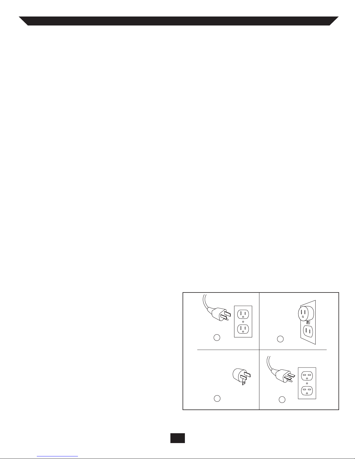
19. This heater is for use on 120 volts. The cord has a
plug as shown at A. An adapter as shown at C is
available for connecting three-blade groundingtype plugs to two-slot receptacles. The green
grounding plug extending from the adapter must
be connected to a permanent ground such as a
properly grounded outlet box. The adapter
should not be used if a three-slot grounded
receptacle is available.
GROUNDING
PIN
METAL SCREW
COVER OF GROUNDED
OUTLET BOX
GROUNDING
MEANS
ADAPTER
GROUNDING
PIN
A
B
C
D
E-2
SAVE THESE
INSTRUCTIONS
When using electrical appliances, basic precautions should allways be followed to reduce the risk of fire,
electrical shock, and injury to persons including the following:
INSTALLATION INSTRUCTIONS
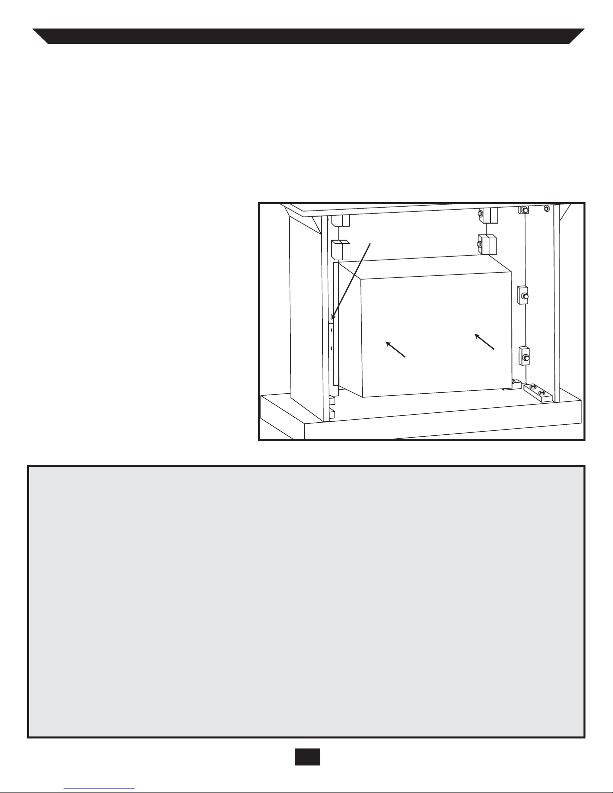
Position your completed Wood Mantel close to its final location. Make sure you can access the back of the
Fireplace, as your Electric Fireplace Insert will be installed from the back.
Using a Phillips head screwdriver, remove the screws and the mounting brackets attached on either side of the fireplaces center opening. Next unpack the Electric Fireplace Insert carefully. Position insert behind fireplace with front
facing the wood mantel. With the help of an adult assistant, lift the Insert and gently slide it into the opening in the
mantel until the flange is flush against the inside of the fireplace. Make sure insert is centered left and right in the
opening. Be careful when placing insert and
adjusting, bottom of insert could scratch the
finish of the wood base/hearth of your fireplace. Re-attach the mounting brackets with
the Phillips head screwdriver, and supplied
screws. DO NOT OVER TIGHTEN.
With the help of an assistant, carefully lift
completed unit and place it with the front
facing out in the final location you have
chosen for your fireplace. Make sure to
secure the electrical cord before lifting or
moving completed fireplace. When choosing
a final location, make sure you will have
clear access to a grounded electrical outlet.
Read and follow all instructions in this
manual before operating your new fireplace.
PARTS LIST
Part Number Description
18-E200200 Ember Bed/Log Grate/Logs
23-E200200 Ember Bed/Log Grate/Logs
28-E200200 Ember Bed/Log Grate/Logs
33-E200200 Ember Bed/Log Grate/Logs
E200300 1,500 Watt Heater
E200301 Cylindrical Fan
E200400 Master On/Off Switch
E200401 Knob for Brightness Control
E200402 Heater On/Off Switch
E200403 Down Light On/Off switch
E200404 Knob for Heater Temperature Control
E200500 E-12 Light Bulb sockets
E200502 Front Projection Screen
Part Number Description
E200504 Sheet Metal Flame Cut-out Screen
18-E200505 Flame Generator/Spinner
23-E200505 Flame Generator/Spinner
28-E200505 Flame Generator/Spinner
33-E200505 Flame Generator/Spinner
E200506 Flame Generator Drive Motor
33-E200506 Flame Generator Drive Motor
E200509 Angled Reflection Hood
28-E200510 Decorative Brick Panels
33-E200510 Decorative Brick Panels
E200603 Assembly Instructions/Warranty
E-3
FIREPLACE
INSERT
BRACKET
FIREPLACE
INSERT
BACK VIEW

Cold climate installation
recommendation: When installing this
unit against a non-insulated exterior
wall or chase, it is mandatory that the
outer walls be insulated to conform to
applicable insulation codes.
Vo ltage: 120VAC, 60 Hz
Total Amps: 12.5 Amps
Watts: 1500 Watts
ELECTRICAL SPECIFICATIONS
A 15 AMP, 120 Volt, 60 Hz circuit with a properly
grounded outlet is required. Preferably, the fireplace
will be on a dedicated circuit as other appliances on
the same circuit may cause the circuit breaker to trip
or the fuse to blow when the heater is in operation.
The unit comes standard with 6’ (1828 mm) three wire
cord, exiting from the rear of the fireplace. Plan the
installation to avoid the use of an extension cord. If an
extension cord must be used, it must be a minimum
ELECTRICAL CONNECTION
When choosing a location for your new fireplace,
ensure that the general instructions are followed.
Also, for best effect, install the fireplace out of direct
sunlight.
POSITIONING/LOCATING YOUR
ELECTRIC FIREPLACE
CLEARANCE TO
COMBUSTIBLES
Keep electrical cords, drapery, furniture and other
combustibles at least 3 feet(0.9M) from the front of
the heater and away from the sides.
TROUBLE SHOOTING GUIDE
PROBLEM SOLUTION
1. No power, switches do not light up 1a. Check that unit is plugged into a standard 120V outlet
2. Switches light up, but no flame effect 2a. Remove front kick plate and check for any broken light
bulbs or loose light bulbs
3. Down lights do not light up 3a. Remove front glass top bracket. Carefully lift glass out
of track. Check that both light bulbs inside the top of
the unit are not broken or loose
4. Logs Glow, flame effect does not work 4a. Open back of unit. Check to see if “spinner” is correctly
mounted at to the rear of unit
4b. Check to see if spinning motor is functioning.
If not, call customer service
5. Flame effect operates, but heater does not 5a. Check that heater switch is in “on”
blow warm air position. Switch should light up.
5b. Make certain that thermostat is turned toward the
“HI” position
14 AWG, three wire with grounding type plug connector and rated not less than 1875 Watts. The cord shall
not be more than 20 feet in length.
CLEANING TRIM
Clean the metal trim using a soft cloth, slightly
dampened with a citrus oil based product and buff
with a clean soft cloth. DO NOT use brass polish or
household cleaners as these products will damage the
metal trim. Citrus oil based products can be obtained
at supermarkets or hardware stores.
E-4
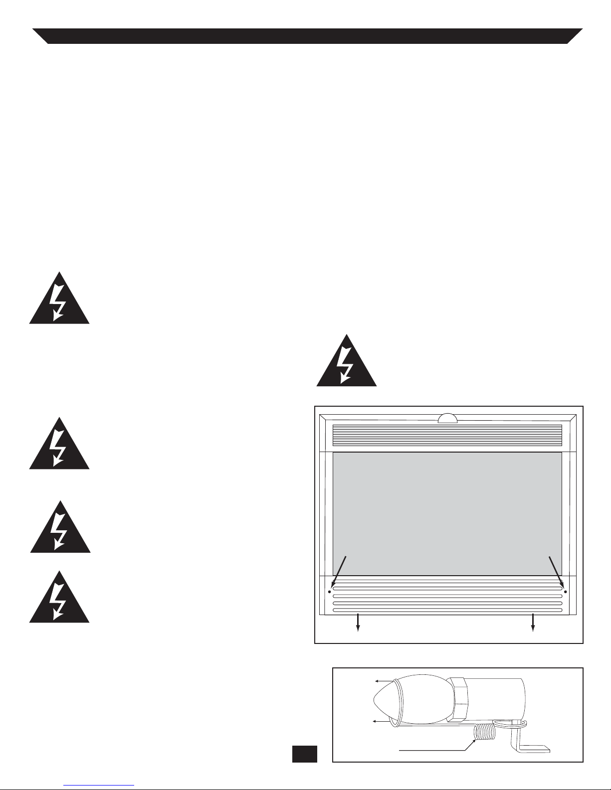
REPLACING THE LIGHT BULBS
(see illustration below). For convenience, if a bulb
burns out, it is a good idea to replace all of the bulbs
at the same time.
1.) Turn the master power switch off, then UNPLUG
the power cord from the wall.
2.) If fireplace has been operating, let the unit cool at
least 2 hours.
3.) Loosen the 2 screws recessed in the front kick plate
(see illustration below). Gently pull the kick plate
towards you (careful not to scratch the fireplace
hearth/base).
4.) Unhook the light bulb spring clip from the bulbs
then unscrew the bulbs. After replacing the bulbs
make sure to replace the light bulb spring clip.
5.) Remove light bulbs and replace with (3) clear 120V,
40 Watt E12 Socket base light bulbs, (2) bulbs for
18E05 Insert, via pull-out tray.
6.) Slide kick plate back into position and tighten
recessed screws. (Careful not to over tighten).
WARNING: Do not exceed 40 Watts per
bulb. Use of higher rated bulbs may
result in a fire, causing property damage or personal injury.
MAINTENANCE OF MOTORS
The motors used on the fan and the flame generator
assembly are pre-lubricated for extended bearing life
and require no further lubrication. However, periodic
cleaning/vacuuming of the fan/heater unit is recommended. The louvers/vent in the control door should
be cleaned periodically, both inside and out. When the
control door is in the open position the heater
grill/screen should be vacuumed. The area around the
controls should also be kept clean. Make sure the unit
is turned OFF and unplugged whenever you are cleaning the heater or fireplace.
WARNING: Make sure the power is
turned off before proceeding. Any electrical repairs or rewiring of this unit
should be carried out by a licensed electrician in accordance with national and
local codes.
If repairing or replacing any electrical component or
wiring, the original wire routing, color coding and
securing locations must be followed.
WARNING: Electrical outlet wiring
must comply with local building codes
and other applicable regulations to
reduce the risk of fire, electrical shock
and injury to persons.
WARNING: Do not use this fireplace if
any part of it has been under water.
Immediately call a qualified service technician to inspect the fireplace and replace
any part of the electrical system.
Wa r ning: Disconnect power before
attempting any maintenance or cleaning to reduce the risk of fire, electrical
shock or personal injury.
E-5
This fireplace uses (3) clear 120V, 40 Watt E12 Socket
base light bulbs (open small base, chandelier candle
type). The 18E05 insert only requires (2) clear 120V,
40 Watt E12 Socket bulbs, installed in a pull-out tray
accessible once the kickplate has been removed. The 40
Watt bulbs are accessed through the front kick plate
1. Loosen reccessed
phillips head screw
3. Remove Kickplate to Access Lightbulbs
4. Replace all Lightbulbs
LIGHT BULB HOLDING SPRING
2. Loosen reccessed
phillips head screw
REPLACING THE
DOWNLIGHT BULBS
models 28E05 and 33E05
This fireplace uses (2) clear 120V, 4 Watt E12 socket light bulbs (open, small base, night light type).
To ols required (1) Philips head screw-driver. For
convenience, if a bulb burns out, it is a good idea
to replace both bulbs at the same time.
1.) Turn the master power switch off, then
UNPLUG the power cord from the wall.
2.) If the fireplace has been operating, let the unit
cool for 2 hours.
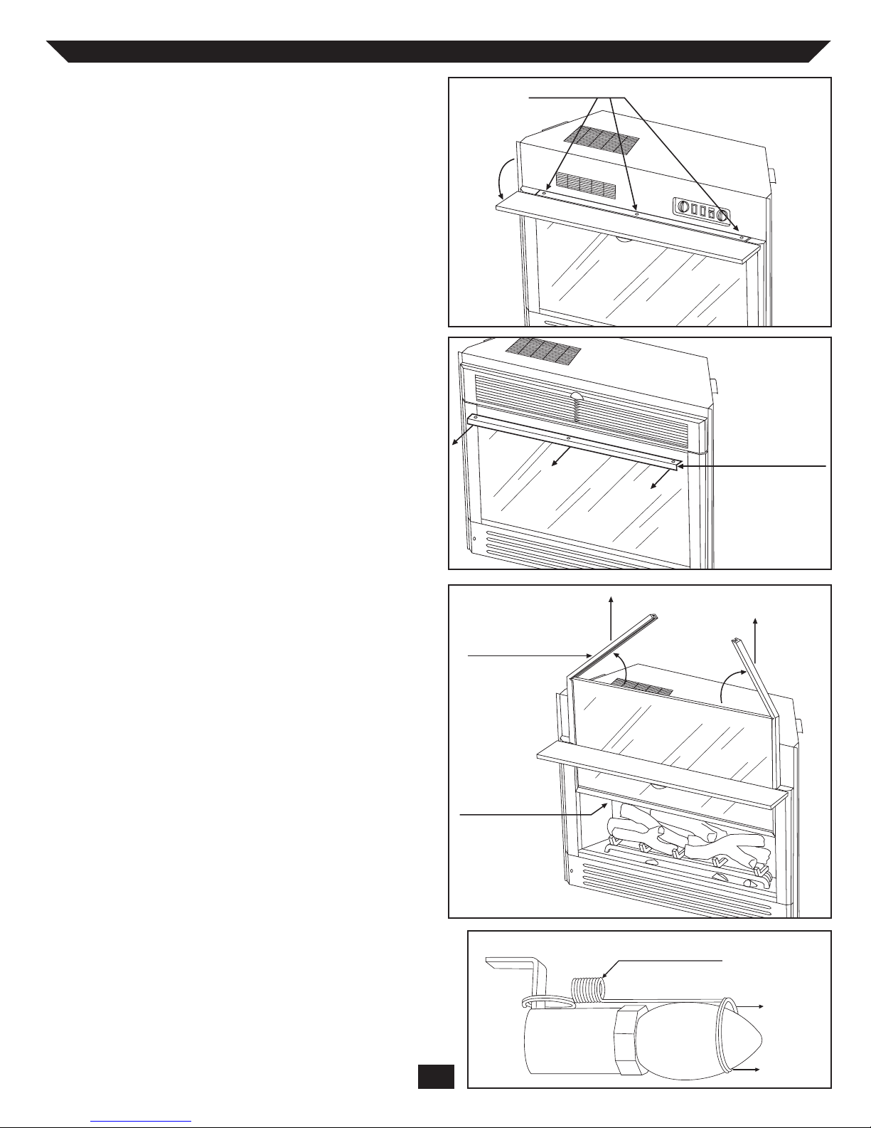
3.) Open control panel door, locate and remove
the 3 screws in/between the door and main
body of the insert (illustration 1).
4.) Close the control panel door and pull the top
glass bracket towards you, away from the front
of the insert (illustration 2).
5.) Open the control panel door, using your hands
grab the rubber glass trim which is split in the
top center (illustration 2). Gently pull up on
the rubber glass trim, this will lift the front
glass up (illustration 3).
6.) Pull the glass only 1/2 of the way up and stop.
Reach underneath to access the downlight
bulbs (illustration 3)
7.) Unhook the light bulb spring clip from the
bulbs (illustration 4) then, unscrew the bulbs.
After replacing the bulbs make sure to replace
the light bulb spring clip.
8.) Follow the same steps in reverse order to reinstall the glass and the top glass bracket.
illustration 1
illustration 2
illustration 3
illustration 4
E-6
3 SCREWS
RUBBER GLASS TRIM
REACH UNDER HERE
TOP GLASS BRACKET
LIGHT BULB HOLDING SPRING
OPERATING INSTRUCTIONS
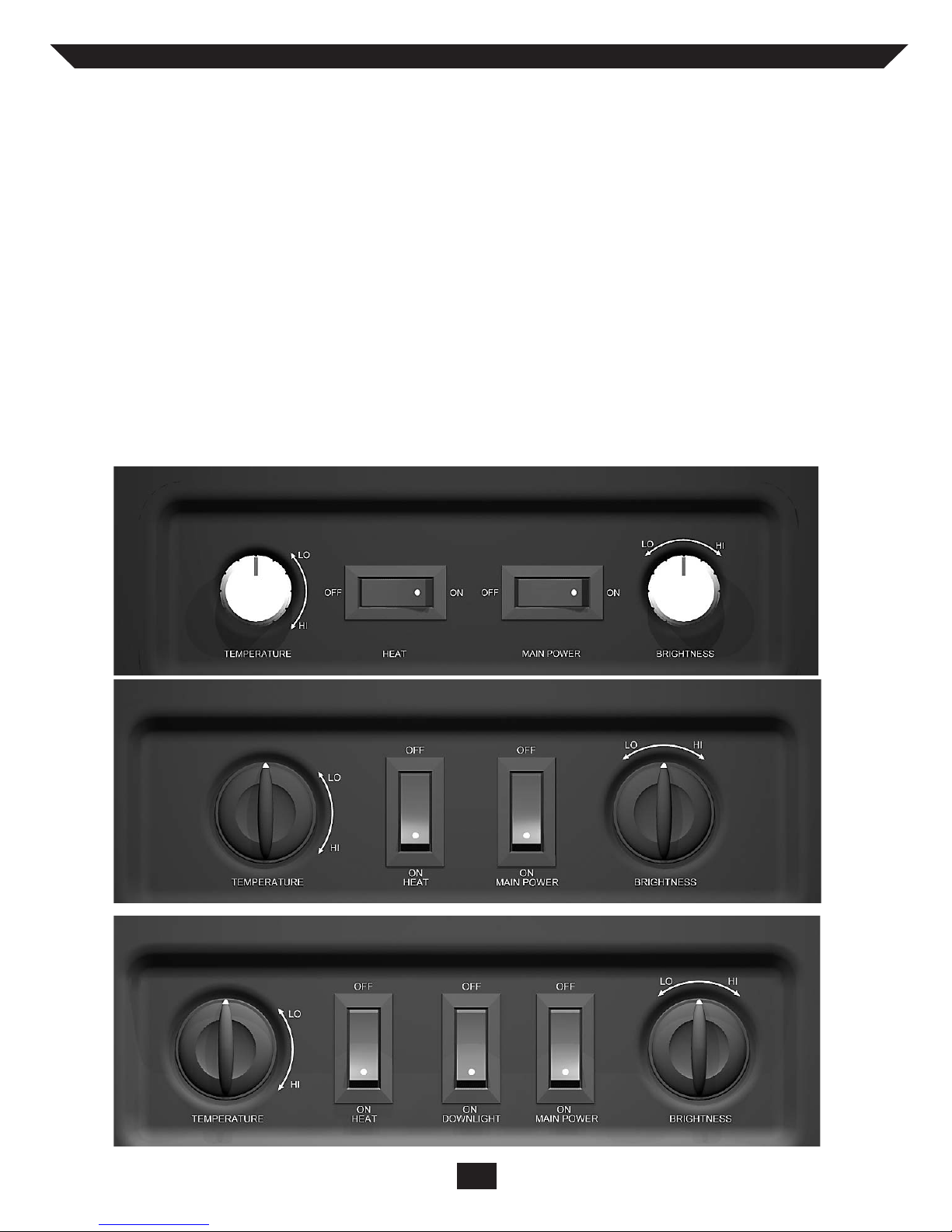
CONTROL FUNCTIONS
MAIN POWER - The Main Power switch supplies
power to all of the functions of the fireplace.
WARNING: During any service of this appliance, the
power to the unit must be turned off. First turn the
main power switch to the “OFF” position. Then
remove the electrical plug from the wall outlet.
HEATER - The Heater switch turns the heater element
and blower motor on and off. Heater should always be
turned on and off by this control only.
DOWN LIGHT (28E05 & 33E05 ONLY) The Down Light switch turns on the down lights that
illuminate inside of the firebox.
3 Switch Control Panel (models 28E05 and 33E05)
2 Switch Control Panel (models 23E05)
2 Switch Control Panel (models 18E05)
E-7
TEMPERATURE - The Temperature control knob
regulates the temperature level of the heater. Turning
the knob clockwise will increase the heat output. The
further the knob is rotated clockwise, the higher the set
point temperature. Turning the knob counter-clockwise will lower the set point temperature.
FLAME BRIGHTNESS - The Flame Brightness
control knob adjusts the flame brightness. Turning the
knob to the left (counter-clockwise) dims the lights and
flame effect. Turning the knob to the right brightens the
lights and flame effect.

BASIC WARRANTY:
Tw in-Star International, Inc. (hereinafter referred to
collectively as the (“Company”) warrants that your
new Twin-star Electric Fireplace is free from manufacturing and material defects for a period of one year
from date of purchase, subject to the following conditions and limitations.
1. This electric fireplace must be installed and operat-
ed at all times in accordance with the installation
and operating instructions furnished with the
product. Any unauthorized repair, alteration, willful abuse, accident, or misuse of the product shall
nullify this warranty.
2. This warranty is non-transferable, and is made to
the original owner, provided that the purchase was
made through an authorized supplier of the company.
3. The warranty is limited to the repair or replacement
of part(s) found to be defective in material or
workmanship, provided that such part(s) have been
subjected to normal conditions of use and service,
after said defect is confirmed by the Company’s
inspection.
4. This warranty does not cover the light bulb(s)
included with the Twin-star Electric Fireplace.
5. The Company may, at its discretion, fully discharge
all obligations with respect to this warranty by
refunding the wholesale price of the defective
part(s).
6. Any installation, labor, construction, transportation,
or other related costs/expenses arising from defective part(s), repair, replacement, or otherwise of
same, will not be covered by this warranty, nor
shall the Company assume responsibility for same.
7. The owner/user assumes all other risks, if any,
including the risk of any direct, indirect or consequential loss or damage arising out of the use, or
inability to use the product, except as provided by
law.
8. All other warranties – expressed of implied – with
respect to the product, its components and accessories, or any obligations/liabilities on the part of
the Company are hereby expressly excluded.
9. The Company neither assumes, nor authorizes any
third party to assume, on its behalf, any other liabilities with respect to the sale of the Twin-star
product.
10. The warranties as outlined within this document
do not apply to non Twin-star accessories used in
conjunction with the installation of this product.
This warranty is void if:
a. The fireplace is subjected to prolonged periods of
dampness or condensation.
b. Any unauthorized repair alteration, willful abuse,
accident, or misuse of the product.
c. You do not have the original receipt of purchase.
IF WARRANTY SERVICE IS NEEDED:
1) Contact the Company, at parts@twinstarhome.com,
or 1-866-661-1218. Make sure you have your warranty, your sales receipt, and the model/serial number of your Twin-star product.
2) ANY AND ALL WORK DEEMED NECESSARY
MUST BE PERFORMED BY A REPAIR SPECIALIST, DO NOT ATTEMPT TO DO ANY SERVICE
WORK YOURSELF.
1 YEAR WARRANTY
For Twin-star™ Electric Fireplace Models
Twin-Star International, Inc.
Delray Beach, FL 33483
In USA: 866-661-1218
In Canada: 866-374-9203
Made in China
Printed in China
revised 05/05
© 2005, Twin-Star International, Inc.
E-8
 Loading...