

Twin-Star International 26MM4995 Instruction Manual

1
INSTRUCTION MANUAL ENCLOSED
MANUEL D’INSTRUCTION À L’INTÉRIEUR
MANUAL DE INSTRUCCIONES ADJUNTO
INSTRUCTION MANUAL ENCLOSED
MANUEL D’INSTRUCTION À L’INTÉRIEUR
MANUAL DE INSTRUCCIONES ADJUNTO
ATTENTION
IF YOU HAVE ANY PROBLEMS OR QUESTIONS, EMAIL
OR CALL CUSTOMER SERVICE BEFORE YOU RETURN
THIS PRODUCT TO THE STORE WHERE IT WAS PURCHASED.
For Customer Service:
www.twinstarhome.com
in English Call: 866-661-1218
ATTENTION
SI VOUS AVEZ DES PROBLÈMES OU QUESTIONS,
ENVOYEZ UN COURRIEL AU SERVICE À LA CLIENTÈLE OU
APPELEZ LE SERVICE À LA CLIENTÈLE AVANT DE RETOURNER
CE PRODUIT OÙ VOUS L’AVEZ ACHETÉ.
Pour le service à la clientèle:
www.twinstarhome.com
pour le service en français: 866-661-1219
ATENCIÓN
SI TIENE ALGÚN PROBLEMA O PREGUNTAS, ENVÍE UN
MENSAJE DE CORREO ELECTRÓNICO O LLAME AL SERVICIO
DE ATENCIÓN AL CLIENTE ANTES DE DEVOLVER ESTE
PRODUCTO A LA TIENDA EN LA QUE LO COMPRÓ.
Servicio de atención al cliente:
www.twinstarhome.com
Línea para llamadas en español: 866-661-1219
STOP
ARRÊT
PARE
STOP
ARRÊT
PARE
1
Français p. 10
ELECTRIC FIREPLACE MANTEL
26MM4995
INSTRUCTION MANUAL
Requires-Electric Fireplace
Requires-Electric Fireplace
Insert with Heater
Insert with Heater
ATTENTION
Twin-Star International, Inc.
Delray Beach, FL 33445
Made in China
Printed in China
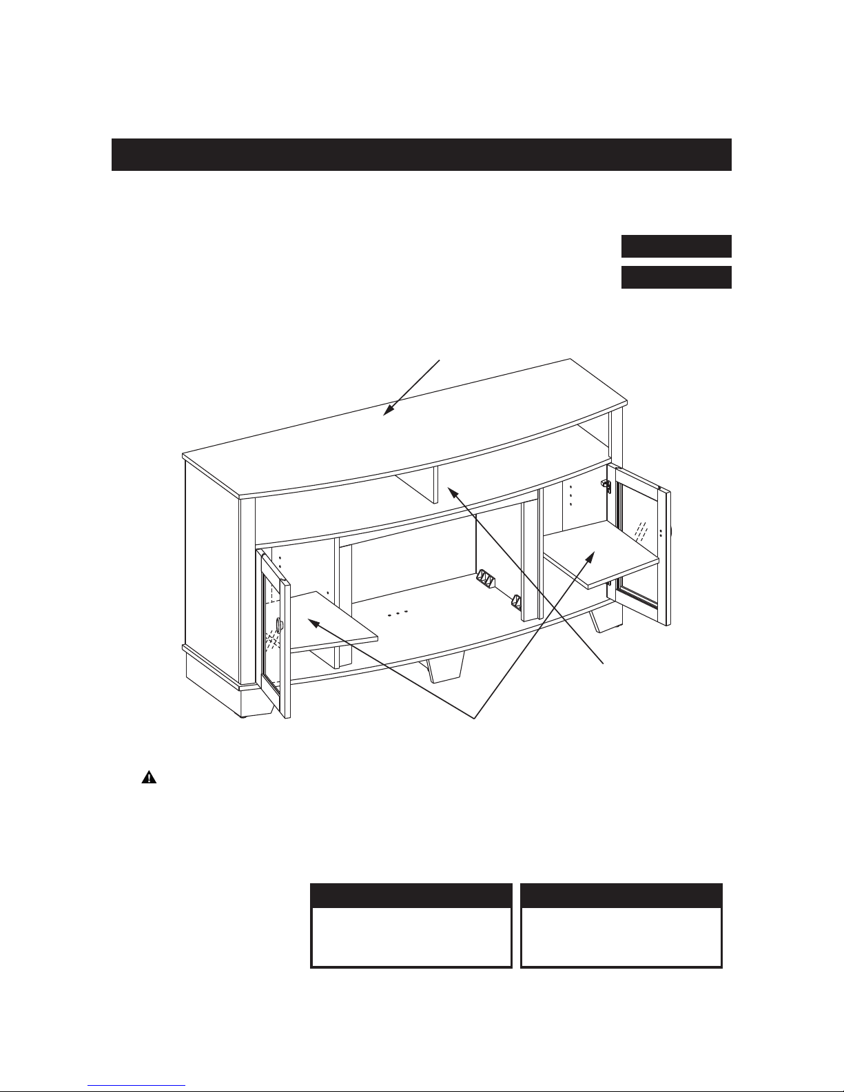
MAXIMUM LOAD 10 lb. (4.5kg)
MAXIMUM LOAD 50 lb. (22.6kg)
CAUTION: This unit is intended for use only with the products and maximum weights
indicated. Use with other products or products heavier than the maximum weights
indicated may result in instability causing possible injury.
Note: Flat Panel TVs with base support should be placed squarely in the center of the
stand with no overhang on any side.
MAXIMUM LOAD 80 lb. (36 kg)
www.twinstarhome.com
English Call: 866-661-1218
Spanish /French Call: 866-661-1219
For Customer Service:
Españo p. 10
Français p. 19
2
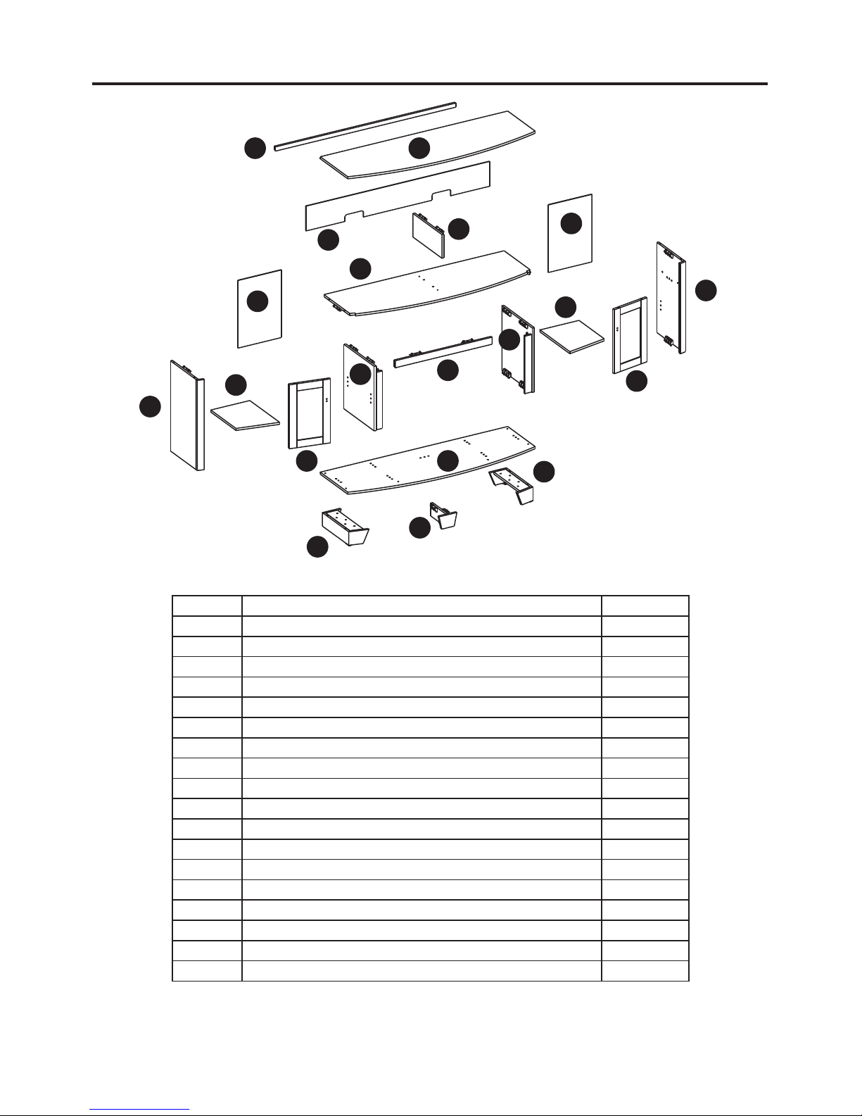
PACKAGE CONTENTS
Part Description Quantity
A Hearth/Base 1
B Center Left Side Panel 1
C Center Right Side Panel 1
D Center Front Panel 1
E Left Side Panel 1
F Right Side Panel 1
G Mantel/Top 1
H Wood Shelf 2
I Side Back Panel 2
J Center Back Panel 1
K Center Shelf 1
L Left Front Door 1
M Right Front Door 1
N Back Cross Panel 1
O Left Foot 1
P Right Foot 1
Q Support Foot 1
S Middle Support Panel 1
G
D
Q
B
A
E
P
C
F
K
S
M
O
N
L
H
H
I
I
J
3
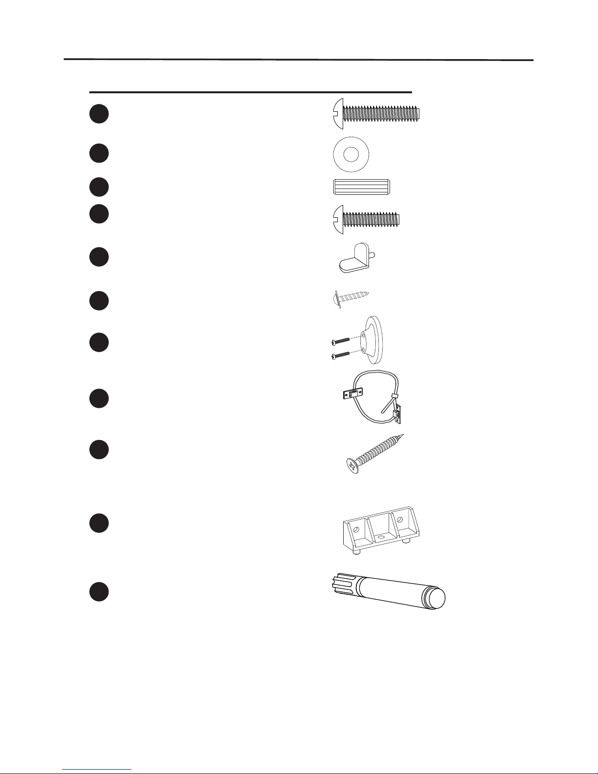
HARDWARE CONTENTS
Part
Description Quantity
Picture
(Shown to size)
Bolt
Bolt
Washer
Wood Dowel
Shelf Pin
Screw
Knob (with bolt)
Screw
Tipping Restraint Hardware
10
21
10
23
8
34
2
8
2
BB
CC
EE
FF
GG
II
HH
AA
DD
Touch-up Pen
Plastic Connector
1
1
ZZ
JJ
4
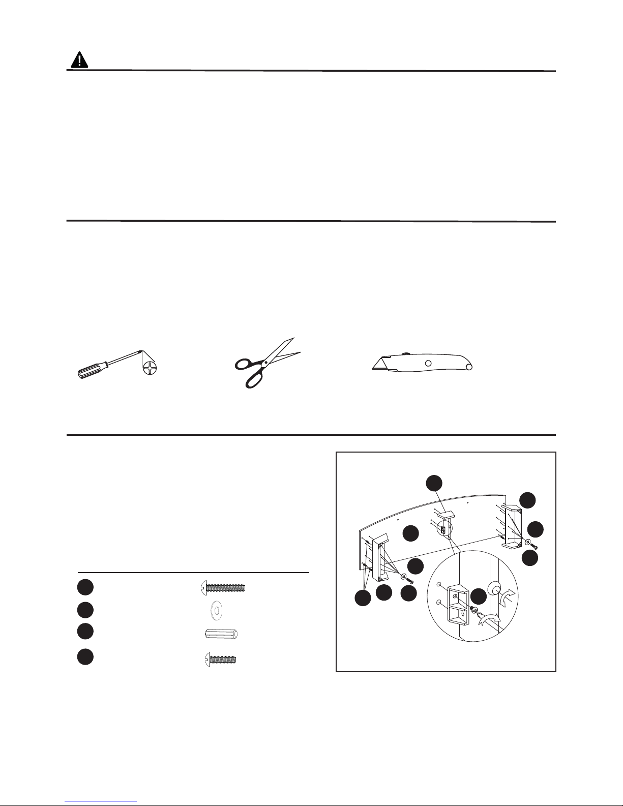
SAFETY INFORMATION
WARNING
• Before assembly, carefully use scissors or utility knife to cut and unwrap all parts.
Make sure you do not discard the hardware.
CAUTION
• Use care in assembling your new fireplace. Take your time and use the hardware
provided and a quality Phillips head screwdriver. Never overtighten bolts.
• Do not sit on any part of the mantel.
• All panels are labeled left and right as viewed from the front of unit.
PREPARATION
Before beginning assembly of product, make sure all parts are present. Compare parts with
package contents list and diagram above. If any part is missing or damaged, do not attempt to
assemble, install or operate the product. Contact customer service for replacement parts.
Estimated Assembly Time: 60 Minutes
Tools Required for Assembly (not included): Phillips head screwdriver, scissors and utility knife
To better protection of your product, please assemble the product on a scratch free groud, and
put a soft material over the groud surface.
ASSEMBLY INSTRUCTIONS
Fig. 1
Hardware Used
1. Insert Wood Dowels (CC) to the holes on the
Hearth/Base (A), push Left Foot (O) and Right Foot
(P) snug to the Base Panel, put Bolts (AA) and
Washers (BB) through the pre-drilled holes in the
Hearth/Base (A) and then tighten.
Attach Support Foot (Q) to Hearth/Base (A), using
Bolts (DD) through the pre-drilled holes in the
Hearth/Base (A) and tighten.
DD
A
AA
AA
CC
BB
BB
O
P
Q
Bolt
x 10
Bolt
x 2
Wood Dowel
Washer
x 6
x 10
DD
AA
CC
BB
5
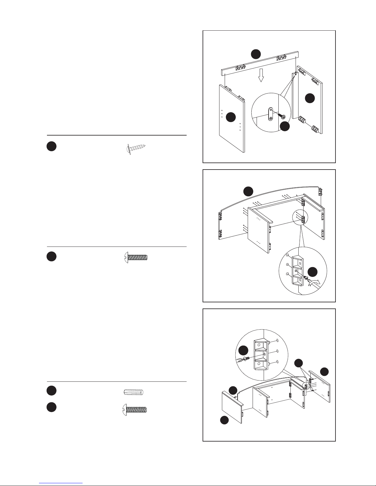
Fig. 2
Hardware Used
FF
Screw x 2
2. Connect the center left side panel (B) and center
right side panel (C) to center front panel (D) by
tightening screws (FF) into pre-drilled holes
corresponding with connection plate on center front
panel (D).
HAND TIGHTEN ONLY.
D
FF
B
C
Wood Dowel
x 4
CC
Fig. 4
Hardware Used
DD
DD
Bolt x 2
Fig. 3
3. Attach to Center Shelf (K) to the completed
assembly from step 2, using Bolts (DD) through the
holes in the Plastic Connector and tighten.
Hardware Used
K
DD
Bolt x 6
DD
E
CC
CC
F
4. Lay down the Completed Assembly from Step 3,
insert one Wood Dowel (CC) into each of the
pre-drilled holes, and push the Left Side Panel (E)
and Right Side Panel (F) snug to the Center Shelf
(K), screw Bolt (DD) to the Center Shelf (K) and side
panels.
HAND TIGHTEN ONLY.
6
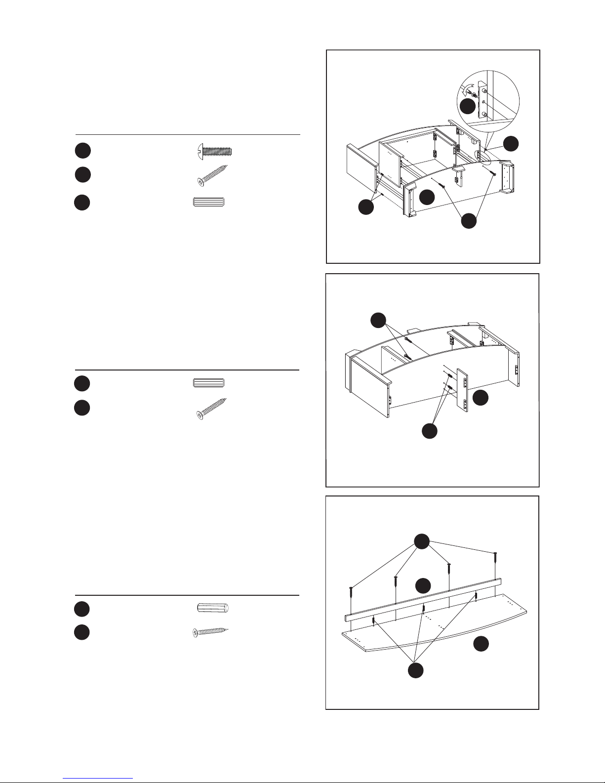
Fig. 6
Fig. 5
Fig. 7
Hardware Used
Hardware Used
Hardware Used
5. Insert Wood Dowel (CC).Attach the Hearth/Base (A)
to the completed assembly from step 4. Using Bolts
(DD) through the pre-drilled holes in the Plastic
Connector.
HAND TIGHTEN ONLY.
7. Insert Wood Dowels (CC) into the holes on the Top
Panel (G), push Back Cross Panel (N) to the Top
Panel (G), using Screws (II) through the pre-drilled
holes in the Top Panel (G) and tighten.
II
II
A
CC
G
N
DD
CC
CC
II
II
Bolt x 6
Wood Dowel
Wood Dowel
Screw
Screw
x 2
x 4
x 2
x 2
II
CC
Wood Dowel
x 3
Screw
x 4
DD
6. Insert Wood Dowel (CC) into the pre-drilled holes of
Center Shelf (K), attach Middle Support Panel (S)
to the Center Shelf (K) and tighten it with Screws (II)
through the pre-drilled holes.
II
CC
CC
CC
S
7
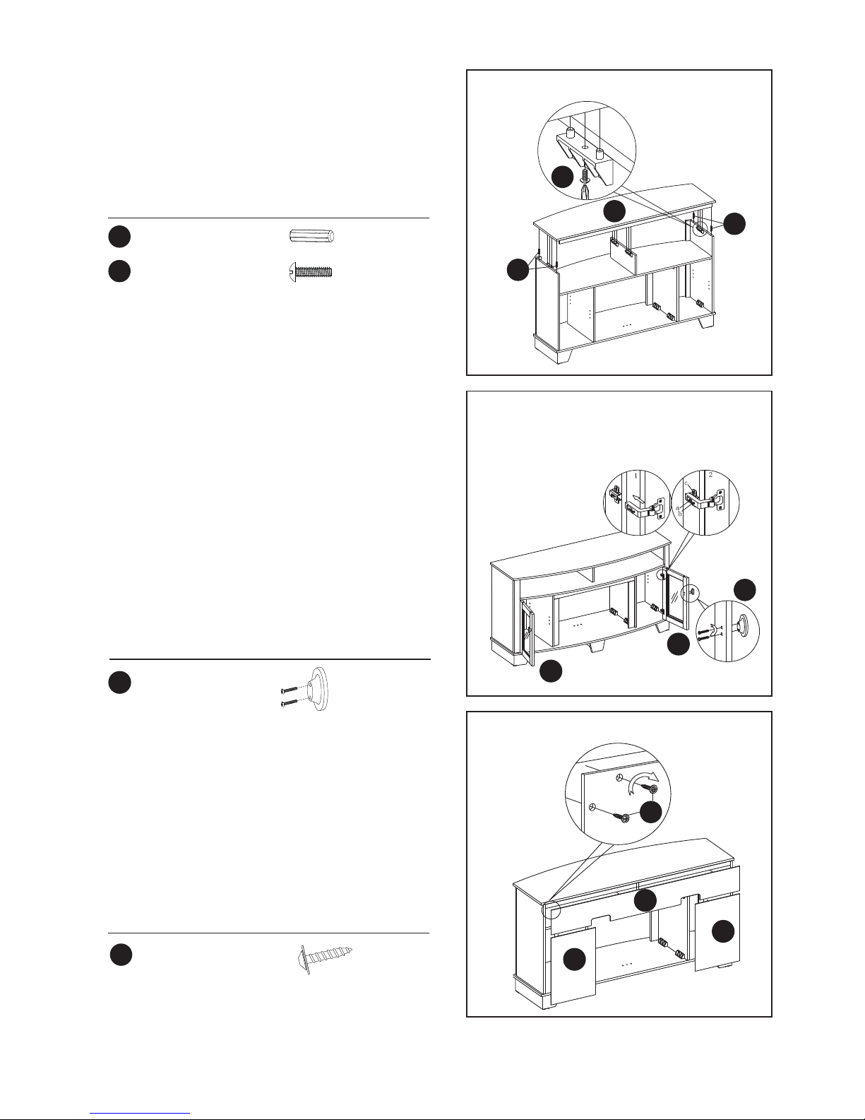
Fig. 8
Hardware Used
8. Insert Wood Dowels (CC) into the pre-drilled holes
on the Left/Right Side Panels (E,F). Locate Top
Panel (G) and lay fi nished side up on top of
completed assembly, using Bolts (DD) through the
pre-drilled holes in the Top Panel (G) and tighten.
CC
CC
DD
G
CC
DD
Bolt
Wood Dowel
x 4
x 4
Fig. 10
Fig. 9
Hardware Used
Hardware Used
GG
Screw x 32
x 2
10. Attach Side Back Panels (I) and Center Back Panel
(J) to the back of the completed assembly from
step 8. Use a Phillips Head Screw Driver, tighten
Wood Screws (FF) through the pre-drilled holes
in the Side Back Panels (I).
9. Locate Right Front Door (M) and Left Front Door
(L). Slide door hinge keyhole into panel hinge
bracket. (Diagram 1)
Use Phillips Head Screwdriver to tighten screws.
(Diagram 2)
TO ADJUST HINGES
To adjust door forward or backward change keyhole
slot position. (As Shown In Diagram 2a)
To adjust door right or left loosen/tighten screw.
(As Shown In Diagram 2b)
To adjust door up or down adjust bracket height.
(As Shown In Diagram 2c)
Attach the Knob (GG) to the Left Front Door (L) and
Right Front Door (M), use the bolts attached through
the pre-drilled holes in the doors. Then use a Phillips
Head Screwdriver to tighten the bolts.
FF
I
I
J
GG
L
M
FF
Knob
8
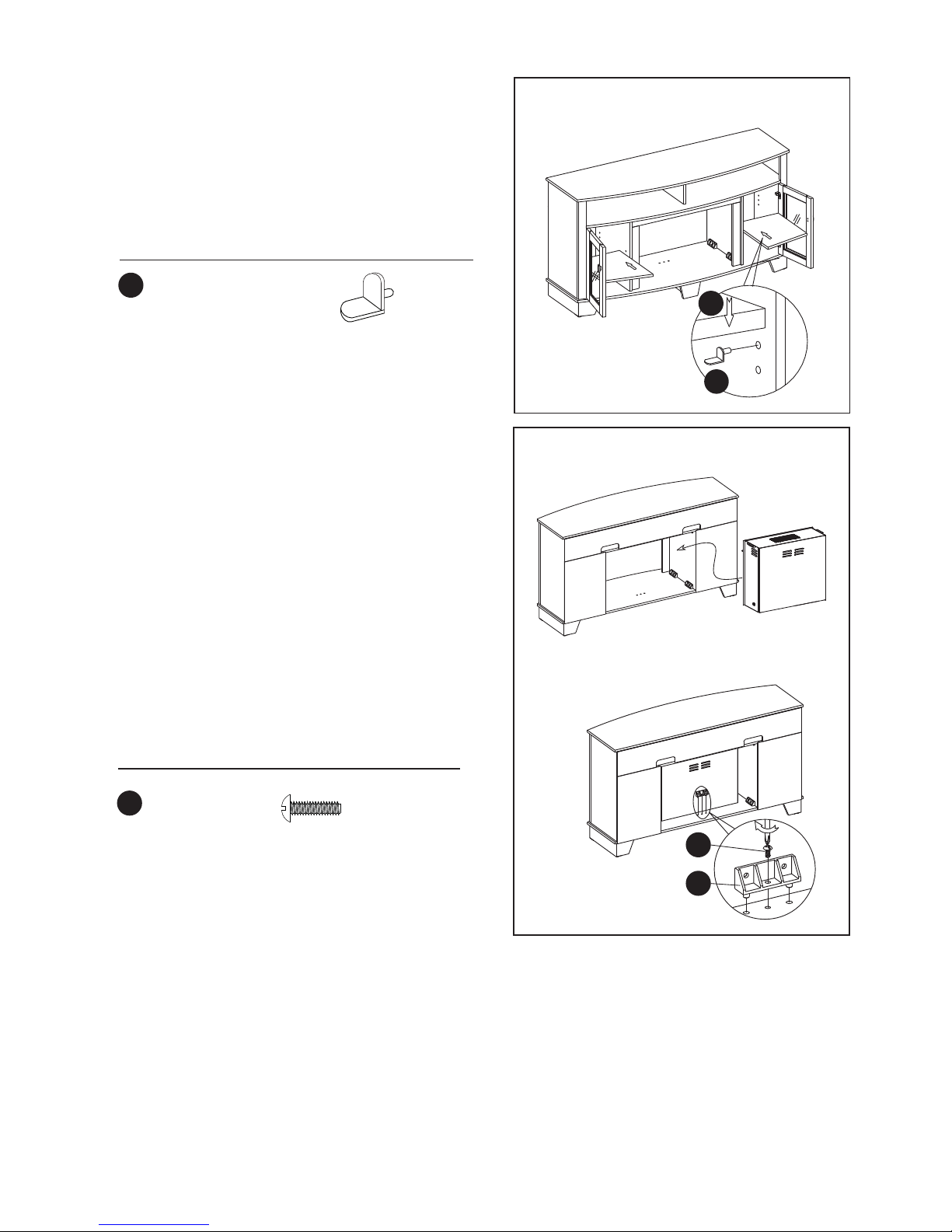
Fig. 12
Completed
Unit
Electric
Fireplace Insert
Install
Insert
From
Back
Fig. 11
Hardware Used
Hardware Used
EE
Shelf Pin x 8
11. Choose desired height of Shelf (H) and place the
four Shelf Pin (EE) into same height shelf holes
inside side panels. Insert Wood Shelf (H), allow
Wood Shelf (H) to rest on the Shelf Pin (EE).
EE
H
12. PLEASE READ ALL “ELECTRIC FIREPLACE
INSERT” INSTRUCTIONS PRIOR TO
INSTALLING ELECTRIC INSERT IN YOUR
COMPLETED FIREPLACE MANTEL. INSTALL
THE INSERT IN YOUR FIREPLACE CLOSE TO
ITS FINAL POSITION.
Lift insert carefully into the back of the unit and
center in the insert opening. Do not drag insert
across hearth/base (A) as it may scratch the unit.
Screw the Bolt (DD) through the plastic connector
(JJ) and tighten.
MOVE YOUR COMPLETED UNIT ONLY SHORT
DISTANCES. MOVE COMPLETED UNIT WITH
GREAT CARE. IT TAKES TWO PEOPLE TO
MOVE COMPLETED UNIT INTO ITS FINAL
POSITION. COMPLETED UNIT INTO ITS FINAL
POSITION.
DD
DD
JJ
Bolt
x 1
 Loading...