

Page 1
Date: 2011-03-11
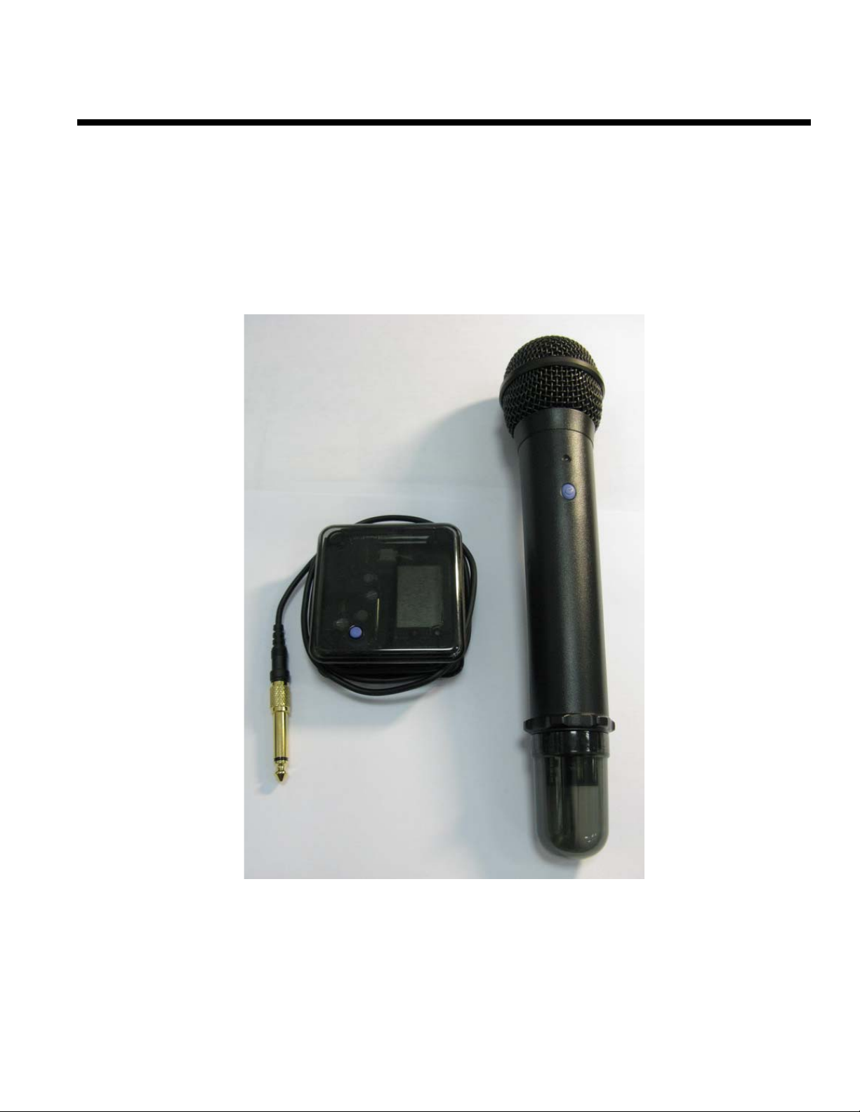
Digital Wireless Microphone
-
User Manual
Product Name:Digital Wireless Microphone
Model No:TF-102
Company Name:TWINKLE
Page 2
Date: 2011-03-11
Digital Wireless Microphone
-
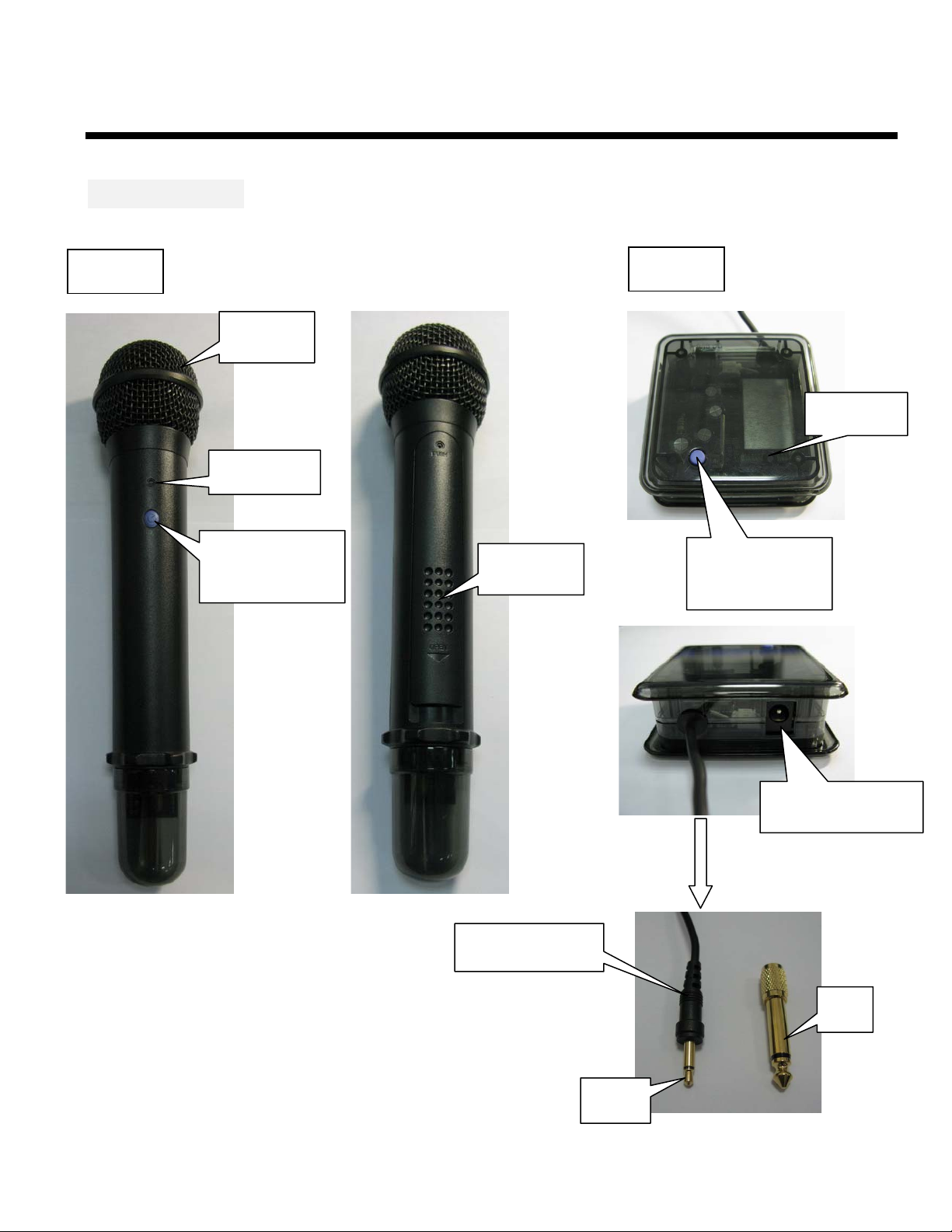
MIC I / O Port
MIC TX
MIC RX
Audio In
Blue LED
Green LED
Power On / Off
Pairing key
3V Battery
Power On / Off
Pairing key
9V 0.65A Adapter
Audio Out Jack
6Φ
3.5Φ
Page 3
Date: 2011-03-11
Digital Wireless Microphone
-
Setup Guide
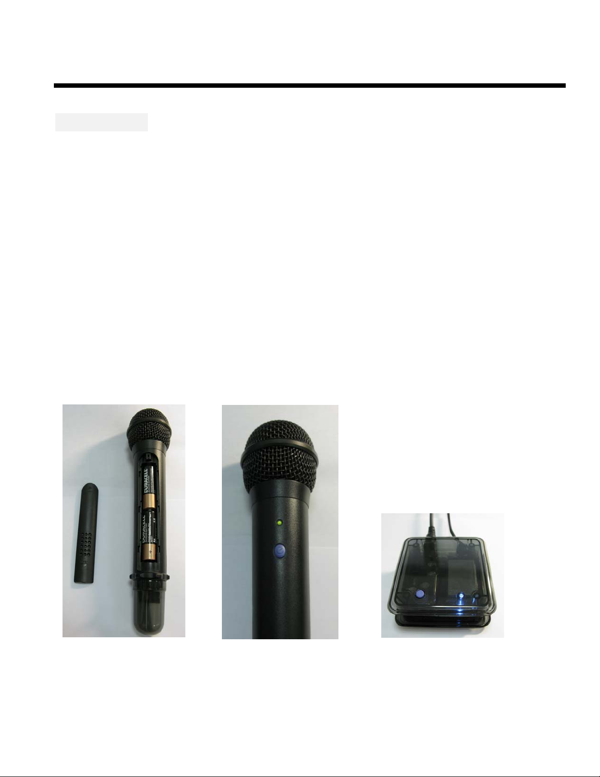
1. Put AA battery 1.5V 2 pcs in the MIC as Graph1 and close the battery cover.
2. Press the blue bottom on MIC to turn on power as Graph 2 and then the green LED will flash
slowly.
3. Connect audio out jack on the receiver to the stereo amplifier.
4. Connect power supply to power jack on the receiver. Press the blue bottom on the receiver as
Graph 3 and then the blue LED light will flash slowly.
5. First press the blue bottom on the MIC for two seconds and then do the same procedure on
the receiver to pair MIC and the receiver. The LED lights will flash quickly while pairing
process.
6. When the LED lights on MIC and the receiver are on, the pairing process is successful.
7. Just enjoy wireless MIC set after successful pairing.
(Graph 1) (Graph 2) (Graph 3)
Page 4
Date: 2011-01-11
2.4G Digital Wireless Microphone
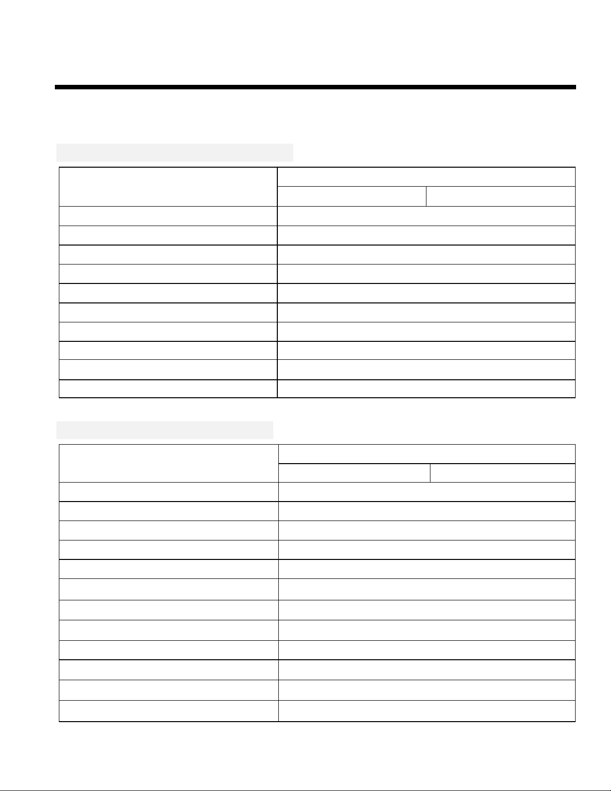
Specification
Wireless Microphone Transmitter
Operation Frequency Range
ID code setting Auto Pairing by Tack Switch
Modulation Type GFSK
RF Output power 6dBm (typ.)
RF Sensitivity - 80 dBm (min.)
Supply Voltage 3V (1.5 V AAA Battery X 2 PCS)
Supply Current 70mA (max.)
Power ON / OFF By Tack Switch
Transmission range 30m (min.)
2400 ~ 2483.5 MHz
2.4GHz ISM Band Hopping mode
Operation Temperature
Dimension 144mm x 25.4mm x1.0mm
0 ℃ ~ + 50 ℃
Wireless Microphone Receiver
2400 ~ 2483.5 MHz Operation Frequency Range
ID code setting Auto Pairing by Tack Switch
Demodulation Type GFSK
RF Sensitivity - 80 dBm (min.)
RF Output power 6dBm (typ.)
Audio Frequency Response 20 Hz ~ 15 KHz
Audio Output Level 560mV (typ.) @ 400mV Audio Input
Supply Voltage 9V DC
Supply Current 80mA (max.)
Power ON / OFF By Tack Switch
2.4GHz ISM Band Hopping mode
Audio Output Connector
Operation Temperature
Dimension 50mm x 53mm x1.0mm
Φ &
3.5
0 ℃ ~ + 50 ℃
6Φ
Page 5

Date: 2011-01-11
2.4G Digital Wireless Microphone
Mapping Table
Search for 28CH Frequency(MHz)
CH0 2408 CH14 2450.5
CH1 2425.5 CH15 2468
CH2 2443 CH16 2418
CH3 2460.5 CH17 2435.5
CH4 2410.5 CH18 2453
CH5 2428 CH19 2470.5
CH6 2445.5 CH20 2420.5
CH7 2463 CH21 2438
CH8 2413 CH22 2455.5
CH9 2430.5 CH23 2473
CH10 2448 CH24 2423
CH11 2465.5 CH25 2440.5
CH12 2415.5 CH26 2458
CH13 2433 CH27 2475.5
Search for 28CH Frequency(MHz)
Page 6

to radio communications. However, there is no guarantee that interference
encouraged
This device complies with Part 15 of the FCC Rules. Operation is subject to the following two conditions: (1)
interference, and (2) this device must accept any interference received,
This equipment complies with FCC radiation exposure limits set forth for an uncontrolled environment. This
Federal Communication Commission Interference Statement
This equipment has been tested and found to comply with the limits for a Class B digital device, pursuant
to Part 15 of the FCC Rules. These limits are designed to provide reasonable protection against harmful
interference in a residential installation. This equipment generates, uses
and can radiate radio frequency energy and, if not installed and used in accordance with the instructions,
may cause harmful interference
will not occur in a particular installation. If this equipment does cause harmful interference to radio or
television reception, which can be determined by turning the equipment off and on, the user is
to try to correct the interference by one of the following measures:
• Reorient or relocate the receiving antenna.
• Increase the separation between the equipment and receiver.
• Connect the equipment into an outlet on a circuit different from that to which the receiver is connected.
• Consult the dealer or an experienced radio/TV technician for help.
This device may not cause harmful
including interference that may cause undesired operation.
FCC Caution: Any changes or modifications not expressly approved by the party responsible for
compliance could void the user's authority
to operate this equipment.
IMPORTANT NOTE:
FCC Radiation Exposure Statement:
equipment should be installed
and operated with minimum distance 20cm between the radiator & your body.
This transmitter must not be co-located or operating in conjunction with any other antenna or transmitter.
" This equipment must be installed and operated in accordance with provided instructions and the
antenna(s) used for this transmitter must be installed to provide a separation distance of at least 20 cm
from all persons and must not be co-located or operating in conjunction with any other antenna or
transmitter. End-users and installers must be provide with antenna installation instructions and transmitter
operating conditions for satisfying RF exposure compliance. "
 Loading...