

Page 1

UUsseerr’’ss MMaannuuaall
Page 2

Table Of Contents
CHAPTER 1
GETTING STARTED 1
Getting Started ................................................................................... 2
Inventory ............................................................................................. 3
Safety and Maintenance .................................................................... 4
Checklists ........................................................................................... 5
Features .............................................................................................. 6
Where to Look For Information......................................................... 7
Quick Start .......................................................................................... 8
Loading Windows .............................................................................. 9
Adjusting the Volume ...................................................................... 10
Adjusting the Brightness ................................................................ 10
Turning off Your Computer............................................................. 11
Making a Startup Disk...................................................................... 11
Tips for New Owners ....................................................................... 11
CHAPTER 2
GETTING STARTED 13
Hardware and Software ................................................................... 14
Front View......................................................................................... 15
Left View............................................................................................ 16
Right View......................................................................................... 17
Bottom View...................................................................................... 18
LED Status Indicators...................................................................... 19
Power Indicators .............................................................................. 20
Function Keys .................................................................................. 20
Numeric Keypad............................................................................... 21
Touchpad .......................................................................................... 21
Connecting the Floppy Disk Drive ................................................. 23
Disk Drives........................................................................................ 23
The CD-ROM, DVD-ROM, Combo Drive, or DVD±RW ................... 24
Connecting the Printer .................................................................... 26
The PCMCIA Card Slot..................................................................... 26
ii
Page 3

Memory.............................................................................................. 27
The Graphics System ...................................................................... 28
Communication Components......................................................... 32
Information about the Wireless LAN button.................................. 33
CHAPTER 3
MAKING CONNECTIONS 35
Making Connections ........................................................................ 36
Left Side Connectors ....................................................................... 36
Right Side Connectors .................................................................... 37
Front Side Connectors .................................................................... 38
CHAPTER 4
SYSTEM SOFTWARE 39
System Software .............................................................................. 40
System Recovery ............................................................................. 41
CHAPTER 5
POWER MANAGEMENT 45
Power Management ......................................................................... 46
Power Saving Modes ....................................................................... 48
Power Saving Tips ........................................................................... 50
When to Replace the Battery .......................................................... 50
Heat Considerations ........................................................................ 51
CHAPTER 6
USING THE BIOS SETUP UTILITY 53
Using the BIOS Setup Utility ........................................................... 54
Navigating and Entering Information in BIOS............................... 55
The Main Menu ................................................................................. 56
Advanced Menu ............................................................................... 57
Boot Menu......................................................................................... 58
Security Menu................................................................................... 59
Change Supervisor Password:....................................................... 60
Change User Password ................................................................... 60
Exit Menu .......................................................................................... 62
APPENDIX A
iii
Page 4

FREQUENTLY ASKED QUESTIONS 63
Frequently Asked Questions .......................................................... 64
APPENDIX B
STATEMENTS 67
Statements........................................................................................ 68
European Notice............................................................................... 71
UL CAUTION ..................................................................................... 71
Canadian Department of Communications ................................... 72
Battery Disposal............................................................................... 73
CAUTION FOR ADAPTER................................................................ 73
BATTERY CAUTION......................................................................... 73
CLASS 1 LASER PRODUCT............................................................ 73
Macrovision DVD License Agreement ........................................... 74
iv
Page 5

CChhaapptteerr 11
IInnttrroodduuccttiioonn
Page 6

Chapter 1 — Introduction
Getting Started
Congratulations on your purchase of the Notebook computer! Your
new notebook features the most innovative advances in portable
computing technology. It combines state-of-the-art ergonomics with
sophisticated architecture to provide you with a personal computer that
is compact, powerful, and easy to use. Designed for a wide range of
general, business, and personal productivity applications, the
notebook is an ideal choice for use in the office, at home, and on the
road.
For maximum expandability without compromising portability, the
notebook accommodates a number of modules, including CDROM/DVD/Combo Drive and 3 USB ports, and one IEEE1394 port.
The high capacity hard disk drive provides you with plenty of storage
space for multimedia files and applications.
This Manual contains all the information you need to set up and use
your new notebook. It describes all the features of the notebook in an
easy-to-read yet thorough manner.
2
Page 7

Introduction — Inventory
Inventory
This computer system is designed for years of productive and
pleasurable computing. Use this section to keep details of your
purchase. This information will be required should you need to make
repairs to your notebook during the warranty period. Update this
section when you add new options.
DATE OF PURCHASE:
PLACE OF PURCHASE:
DEALER'S NAME:
DEALER'S ADDRESS:
TELEPHONE:
E-MAIL ADDRESS/WWW:
CONTACT PERSON:
MODEL NUMBER:
SERIAL NUMBER:
BIOS VERSION:
The serial number is on the label (with a bar code) on the bottom side
of the computer. The BIOS revision number will appear briefly on the
screen after turning on the computer, before the graphic BIOS screen
appears. Press the Pause key to keep the number on the screen so
you can record it.
3
Page 8

Chapter 1 — Introduction
Safety and Maintenance
You can use your computer under a wide range of environmental
conditions. However, to ensure long use and continued high
performance, consider the following factors when setting up your
computer:
• Follow all warnings and instructions noted in this documentation
and in the Windows Help program.
• The first time you use your computer, we recommend that you
carefully read the Making Connections section of this manual
and initialize the battery to ensure optimum battery performance.
• Unplug the computer from the power outlet before cleaning. Use
a damp cloth for cleaning. Do not use aerosols, solvents, or
strong detergents.
• Do not use the computer near open water or other liquids. Never
spill liquid onto the computer.
• Do not place the computer in an unstable location where it might
slip or be knocked over. Seriou s damage could result from a fall.
• Slots and openings in the system cabinet are for ventilation
purposes. Do not block or cover these openings or the system
could overheat. Do not use or store the computer near a source
of heat or dust.
• On the base or rear panel of this notebook, there is a label with
information on the power requirements of this system. These
requirements must be followed. If you are unsure of your local
power supply, consult your dealer or local Power Company.
• Do not step on or place anything on the power cord.
• If you use the computer with an extension cord, ensure that the
total ampere ratings of all the devices sharing the extension do
not exceed the rating of the extension cord or the rating of the
wall outlet.
• Never push foreign objects into the computer through any of the
slots or openings. Dangerous voltages are present, which could
cause electric shock or fire, or damage sensitive components.
• For best results, use a power strip with a built-in surge prote ctor.
Do not use inferior extension cords as this may result in damage
to your computer.
4
Page 9

Introduction — Checklists
• Set the computer on a flat, stable surface. To prevent damage to
the computer’s hard disk drive, avoid using the computer where
it will be exposed to strong vibration.
Checklists
After opening the package, carefully inspect the contents. If any of the
items is missing or appear damaged, contact your dealer. The
shipping carton should contain the following:
STANDARD
• A notebook computer with a hard disk drive
• An internal battery
• A CD-ROM/DVD-ROM/Combo/ DVD-RW drive
• An AC adapter with power cord
• User's Manual
• System software CD-ROMs
• Anti-electromagentic wave clip
OPTIONS
The following items are normally optional, but some vendors may
include them in the standard package. Some items may not be
available in some countries, or some vendors may choose not to carry
all the items.
• 512 or 256 MB SO-DIMM memory card
• A Carry bag
• A FDD
• An operating system manual
5
Page 10

Chapter 1 — Introduction
Caution: When purchasing any of the accessories
listed above, purchase only those accessories that
are approved for use with your computer. The above
accessories are proprietary items. Your system vendor
can obtain these approved accessories. If you use
items that are not approved for use with this
computer, you may cause your computer to malfunction,
or to emit or receive electro-magnetic radiation in
excess of local regulations. For non-proprietary
accessories such as PC cards or printers, ensure that
the accessory functions properly in your computer
before making the purchase. Your system vendor may be
able to recommend reliable brands and models.
Features
High Capacity Hard Disk Drive
The computer has a high capacity hard disk drive, to store your favorite
programs and large multimedia files.
Built-in Modem/LAN Capability
A built-in 56k modem and 10/100 Mbps Ethernet port allows you to access
the Internet or a local area network (LAN).
Large LCD
Your computer has an easy-to-view XGA/SXGA+ LCD panel.
Built-in Stereo Speakers and Microphone
The stereo speakers and internal microphone enable you to run a variety of
multimedia applications.
Convenient Audio Control
The conveniently located audio control knob enable you to easily adjust the
volume to the stereo speakers.
Function Keys
Function keys give you easy control of power management and your
monitor.
Scrolling Button
Comfortably scroll through documents with the ergonomically designed
scrolling button.
6
Page 11

Introduction — Where to Look For Information
Where to Look For Information
About Your Computer
This User’s Manual describes the key elements of your computer.
New users can find a simple step-by-step orientation in the Quick
Start section of this chapter.
About Windows
The Windows Manual provides an overview of the Windows operating
System. Windows Online Help, found on the Start menu, offers extensive
Windows assistance. Welcome to Windows offers an online orientation for
new Windows users. Find it in:
Start / Programs / Accessories / System Tools.
7
Page 12
Chapter 1 — Introduction
Quick Start
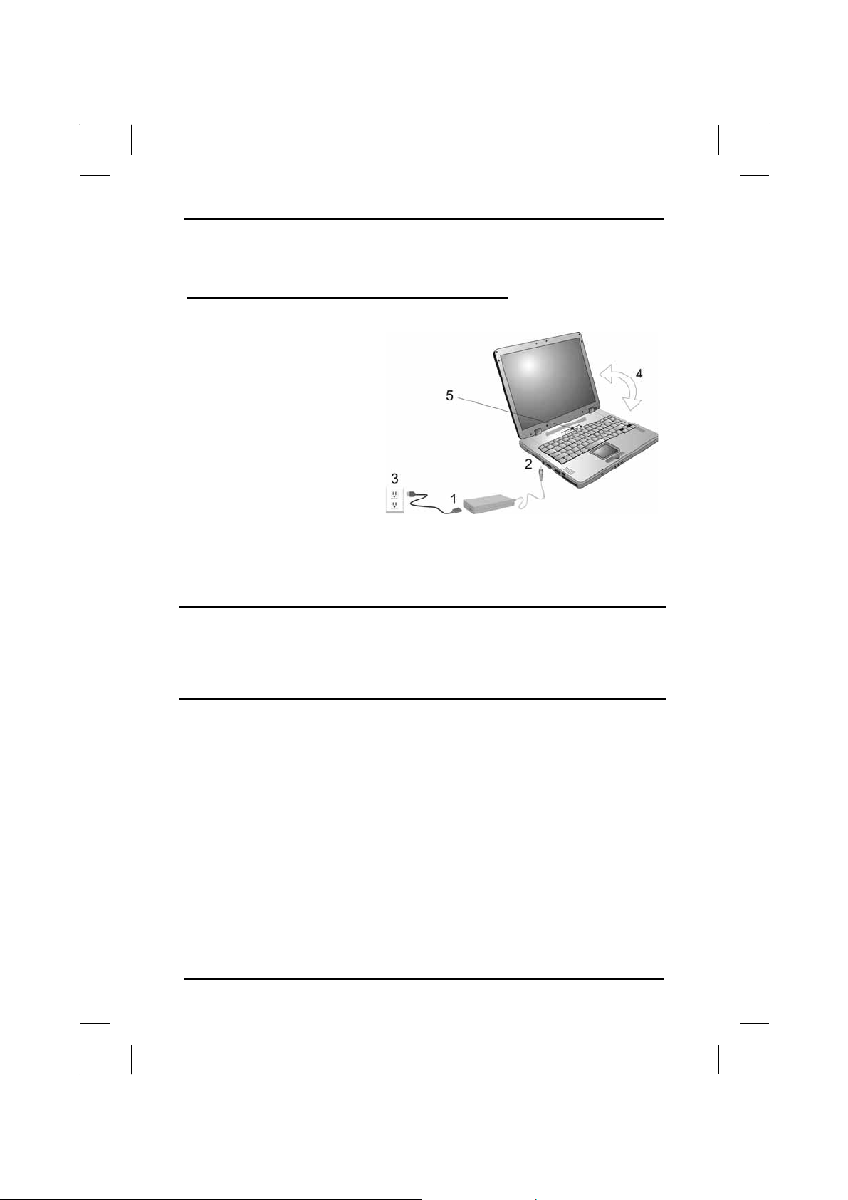
Turning on the Computer for the First Time
1. Connect the AC adapter
power cord to the AC
adapter.
2. Connect the AC adapter
to the DC power port on
the left side of your
computer.
3. Connect the AC adapter
power cord to an AC
outlet.
4. Open the LCD panel to
a comfortable viewing
angle.
5. Press the power button
to turn on the power.
Note: The battery is not fully charged. Allow your battery to
fully charge before using it (i.e., before
disconnecting AC power). Calibrating the battery before
use is also highly recommended. Refer to Chapter 5,
Power Management, for further information.
Use the touchpad to move the cursor on the screen. Move your finger
across the pad to control the cursor, and press the right and left
buttons beneath with your thumb. These buttons have the same
functions as the right and left buttons of a standard mouse. You can
also click or double-click by tapping on the touchpad. The middle
button can be used to scroll up and down in documents and Web
pages.
8
Page 13
Introduction — Loading Windows
Loading Windows
The following section is for installing the Windows operating system
only. If you are installing a different operating system, please check
with your vendor for installation details.
Your computer will
begin loading Windows
once you turn on the
power. Wait a few
seconds for Windows
setup to load. The
Windows setup will
prompt you for the
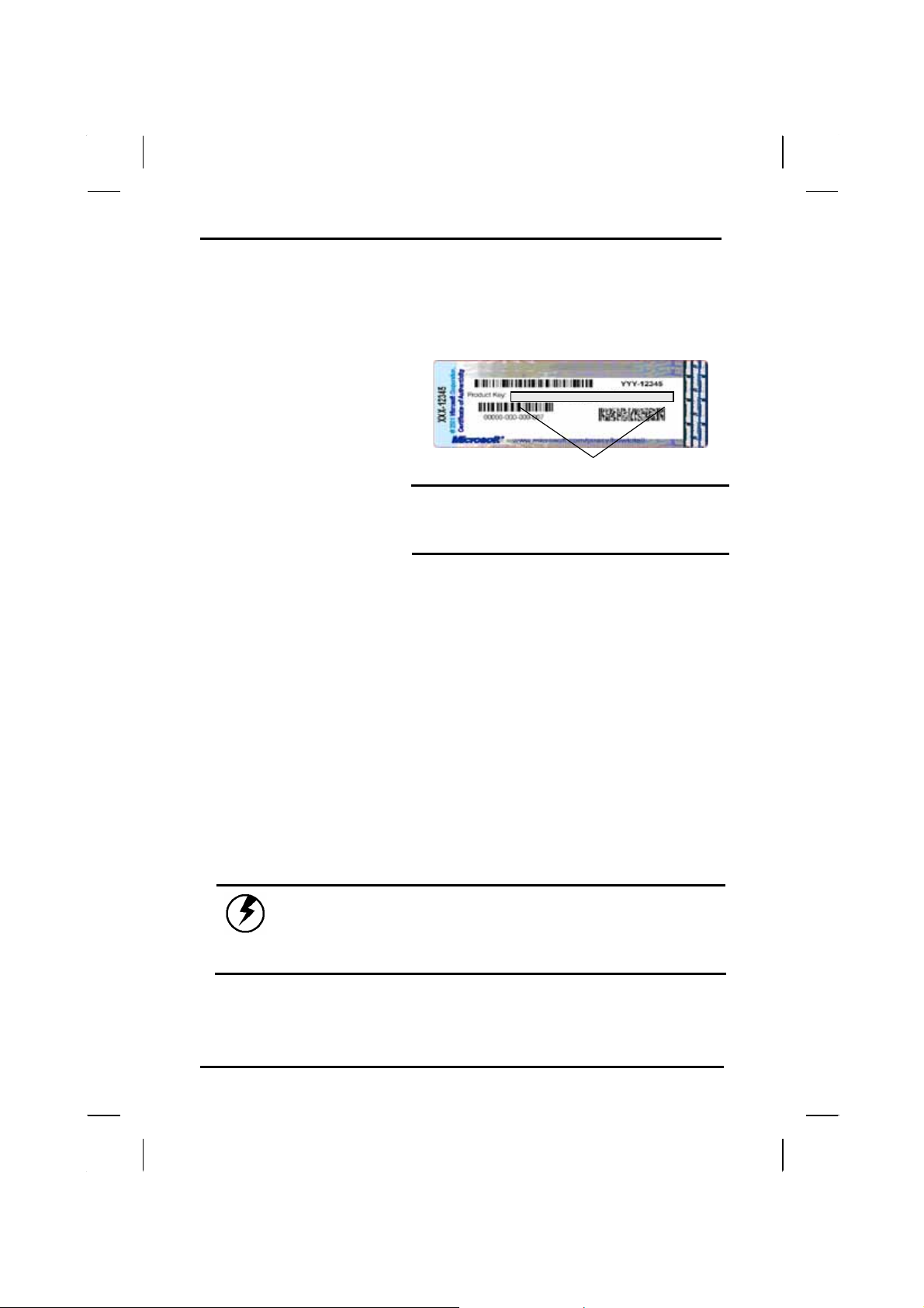
product key number,
shown to the right:
Note: The product key is on a
sticker attached to the bottom
of the Notebook.
1. Type your name, and, if applicable, the name of your company.
2. Read the End User's License Agreement. Click Next to accept it.
3. Enter the product key number. You can find this on the
Certificate of Authenticity on a sticker attached to the computer.
Click Finish.
4. The Start Wizard will prompt you to set the date, and your local
time.
Product key num ber
After the Start Wizard updates your system settings, the Welcome to
Windows screen will appear. You may disable this feature by clearing
the check box labeled show this screen each time Windows starts.
Some software comes preloaded with Windows. New users can
familiarize themselves with this software by selecting Programs from
the start menu, then clicking on programs to run them.
Caution: When you are installing the Windows
operating system and enter the product key number,
we STRONGLY recommend connecting the AC adapter(do
NOT use battery alone)to avoid warning message.
9
Page 14
Chapter 1 — Introduction
Adjusting the Volume
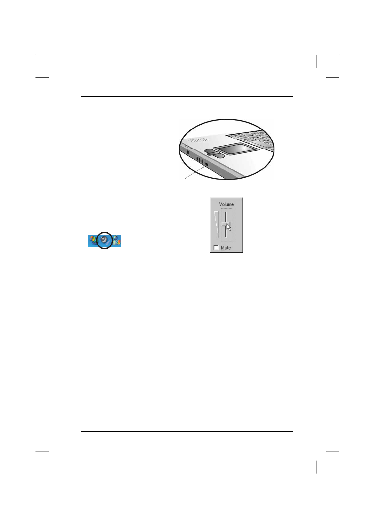
You can adjust the volume
with the volume control knob
located below the touchpad.
Volume
Control Knob
Alternatively, you can adjust
the volume with the Windows
volume control applet located
on the taskbar.
Adjusting the Brightness
Use the following hot key combinations to adjust the LCD panel
brightness:
• Fn + F6 decreases the brightness
• Fn + F7 increases the brightness
10
Page 15
Introduction — Turning off Your Computer
Turning off Your Computer
Turning off the computer properly is important to maintaining your
computer.
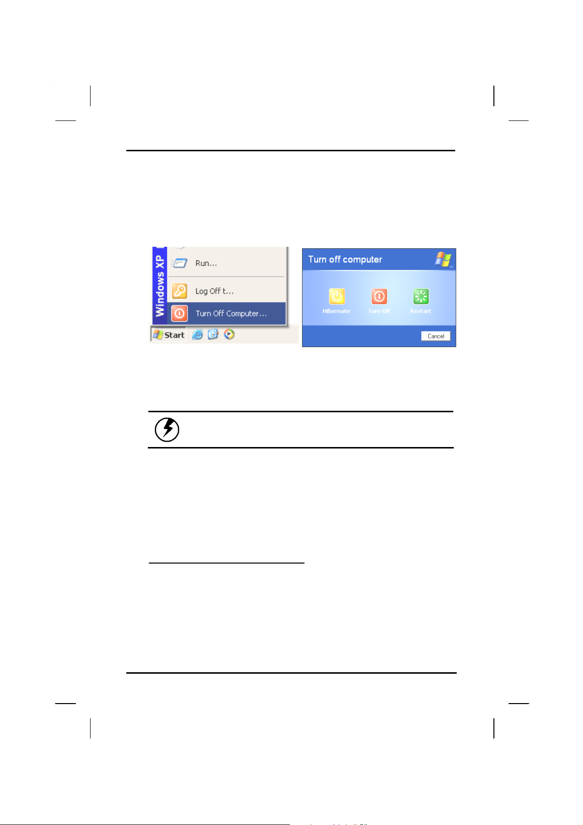
1. On the Start menu, cli c k Turn
Off Computer.
If you are going to be away from the computer for a short period, there
are ways of conserving power without shutting down the system. See
Chapter 5, Power Saving Modes, for details.
Warning: Shutting off the computer improperly
may result in data loss.
2. Click the Turn Off button.
Making a Startup Disk
If you have trouble starting Windows, the startup disk can be used to
start your computer and fix many problems. Refer to the Windows user
manual for instructions.
Tips for New Owners
Take responsibility for backup
Back up files often. Users who need to manage large amounts of data
may wish to use backup devices such as a tape backup unit or a ZIP
drive. If you use your notebook as a networked workstation with
system backup, talk to the system administrator about backup
procedures for your notebook.
11
Page 16

Chapter 1 — Introduction
Don't leave passwords anywhere on your notebook or
carrying case
Be careful when placing your notebook on an airport
security conveyor belt
In most airports, security conveyor belts are safe for computers. If you
are not sure, ask the security staff. You should keep a close eye on
your computer. When you are in a hurry, make sure that you walk
away with the correct notebook computer!
Tape your business card to the notebook and accessories
In the workplace, notebooks and accessories may often look exactly
alike, leading to equipment mix-ups. Prevent such mix-ups by placing
your name on your equipment.
Develop ergonomic work habits
The science of ergonomics studies the relationship between health
and a suitable work environment. For more information on ergonomics,
contact your nearest computer bookstore, or local library. The Internet
also has information on this and other related subjects.
Never take the notebook anywhere without the carrying
case
A broken screen or case can be costly to repair. Prevent accidents by
carrying the computer in a suitable carrying case.
Consider using a lock
For added security, consider purchasing a Kensington lock to put into
the Kensington lock hole on the left side of your computer (see
Chapter 2, Left View). Use the Kensington lock to secure the computer
to a desk or table.
Note: Using a computer for extended periods of
time with a poor workstation setup and incorrect
work habits can cause health problems.
12
Page 17

CChhaapptteerr 22
Geettttiinngg SSttaarrtteedd
G
Page 18

Chapter 2 — Getting Started
Hardware and Software
This chapter introduces the different components and controls of your
notebook computer, including the hardware components, the software, and
the audio and video systems.
Getting Started
Before you begin using your computer, read this chapter to familiarize
yourself with the main components installed in the system.
First, gently lift the cover using both hands and open up the computer.
14
Page 19
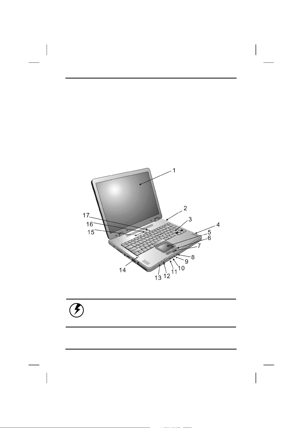
Front View
Getting Started — Left View
1. LCD panel
2. Battery
3. Keyboard
4. Speakers
5. Touchpad
6. Touchpad buttons
7. Scrolling button
8. Volume control knob
9. Microphone-in jack
10. Audio-out jack for external
speakers or headphones
11. SPDIF jack
12. IEEE1394 port
13. Power indicators
14. Microphone
15. Activity indicators
16. Power button
17. Wireless LAN power button
Warning: The wireless communications antenna is
located in upper right-hand corner of the cover,
Please avoid hitting it so communications quality
will not be affected.
15
Page 20
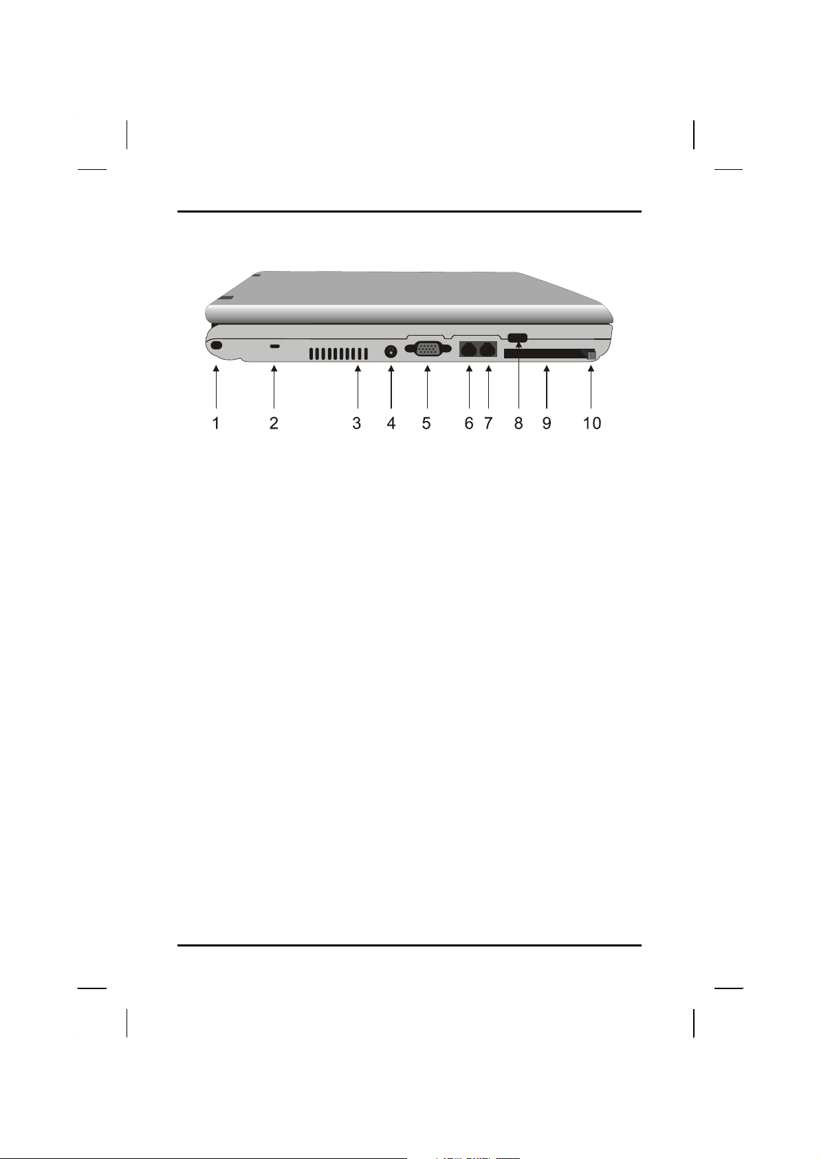
Chapter 2 — Getting Started
Left View
1. Shoulder strap hole
2. Kensington lock hole
3. Ventilation slots
4. DC-adapter port
5. VGA port external video display
6. LAN RJ-45 jack
7. RJ-11 jack
8. USB port
9. PCMCIA card slot
10. PCMCIA card eject button
16
Page 21
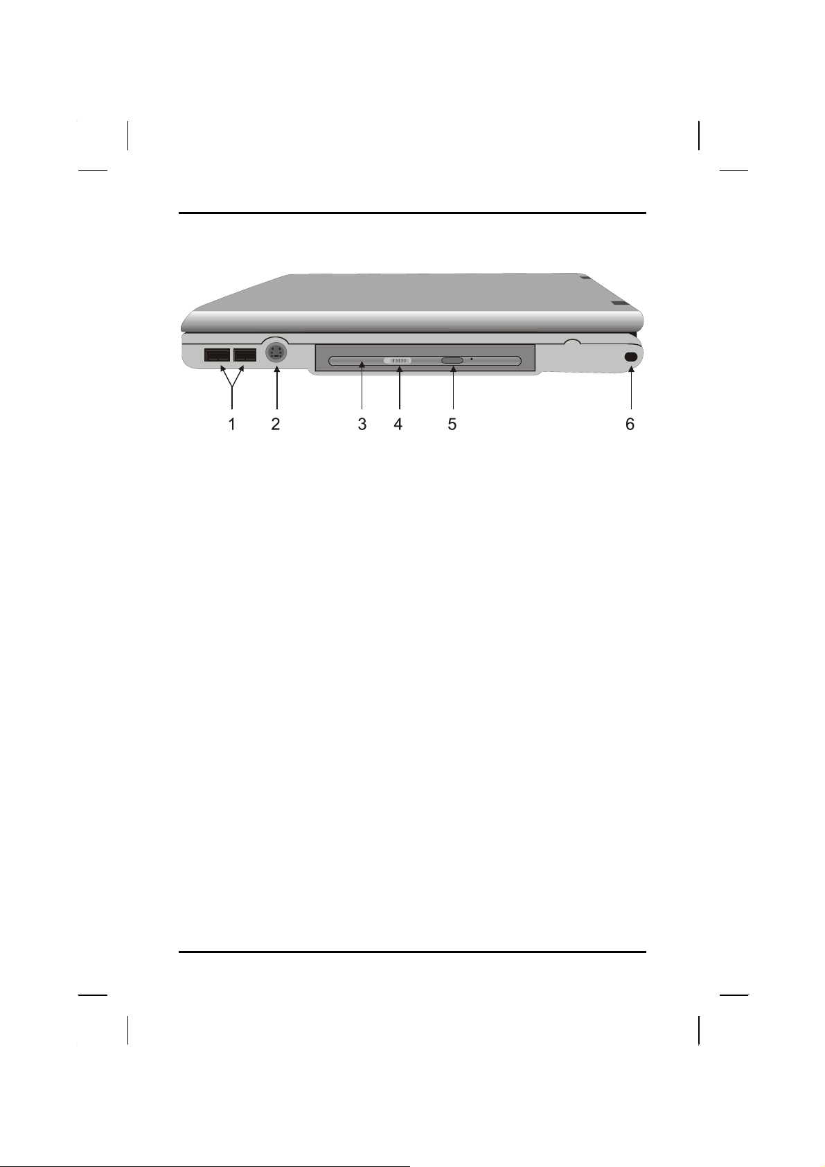
Getting Started — Bottom View
Right View
1. USB ports
2. S-Video port
3. CD-ROM/DVD-ROM/Combo/DVD±RW drive
4. CD-ROM/DVD-ROM/Combo/DVD±RW drive lock
5. CD-ROM/ DVD-ROM/Combo/DVD±RW drive eject button
6. Shoulder strap hole
17
Page 22
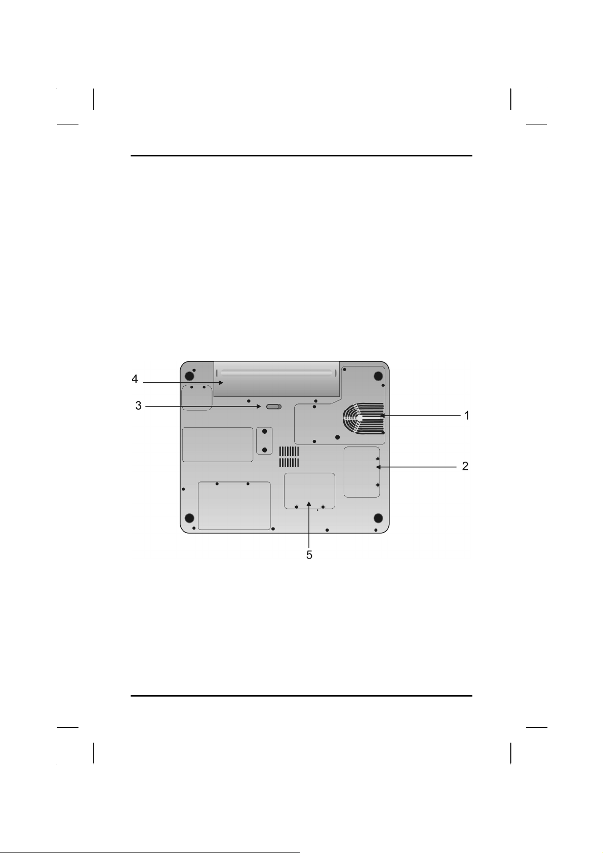
Chapter 2 — Getting Started
Bottom View
1. Ventilation slots
2. WLAN Module
3. Battery release button
4. Battery
5. SO-DIMM DDR RAM Module
18
Page 23
Getting Started — LED Status Indicators
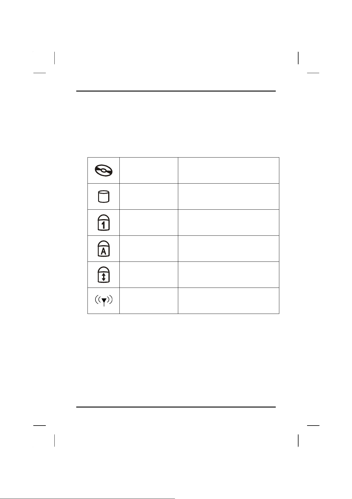
LED Status Indicators
The status indicators in the upper left corner of the keyboard light up when
a particular function of the computer is active. Each indicator is marked with
a symbol.
The computer is reading information
CD ROM Drive
from the CD-ROM, CD-RW or the
DVD ROM drive.
The computer is reading from, or
writing to the built-in hard disk.
The keyboard is in Num-Lock mode.
Number-Lock
HDD
Caps-Lock
The keyboard is in Caps-Lock mode.
Scroll-Lock
The keyboard is in Scroll-Lock mode.
Wireless LAN
The Wireless LAN is accessing.
19
Page 24
Chapter 2 — Getting Started
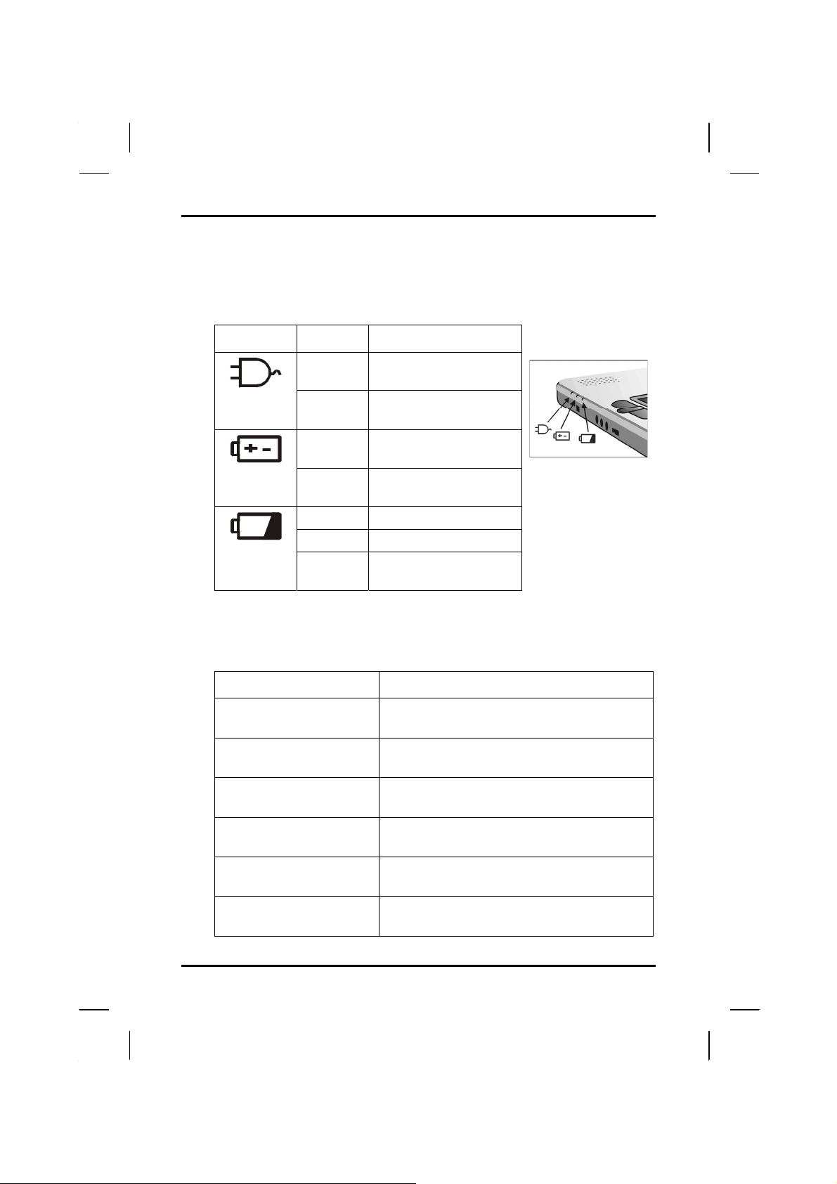
Power Indicators
The power indicators show which power source the system is using. They
also show battery status and low battery power alerts. The power indicators
remain active and viewable even when the LCD panel is closed.
Icon Light Description
Green
Flashing
Green
Green
Flashing
Green
Green Battery fully charged
Orange Battery charging
Flashing
Red
Power is on and the
AC adapter is in use
Power is in suspend
mode
Power is on and the
battery is in use
Power is in suspend
mode
Battery power
critically low
Function Keys
Hold the Fn key while pressing the numbered function key.
Function key Description
Fn + F1
Fn + F2
Fn + F3
Fn + F6
Fn + F7
Fn + F10
Toggles display on/off
Toggles between LCD/CRT displays
Suspend to RAM/HDD
Decreases LCD brightness
Increases LCD brightness
Speaker Mute On/Off
20
Page 25
Getting Started — Touchpad
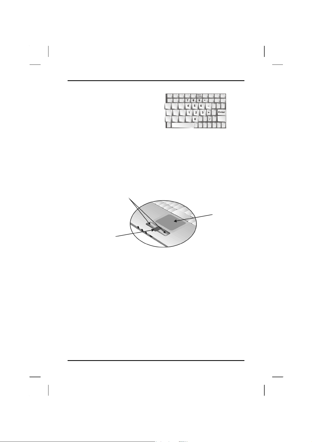
Numeric Keypad
The embedded numeric keypad
consists of ten keys that make
number intensive input more
convenient. Press <NumLock> to
enable or disable the numeric
keypad.
Touchpad
The touchpad is a pressure sensitive pointing device that provides all the
features of a two-button mouse. Its primary function is to move the cursor
around the screen.
Touchpad
Botton
Touchpad
Scrolling Button
The instructions listed below describe how to use the touchpad.
1. First, place your fingers on the keyboard in the normal typing
position. The touchpad is easily accessible by moving either your
left or right thumb off the space bar and on to the touchpad.
2. Gently move your thumb across the pressure-sensitive touchpad in
the direction you want the cursor to move. The pad detects the
change in pressure and moves the cursor in the corresponding
direction.
3. The touchpad offers another method of making selections in a
software program. It is called double-tapping. This function
corresponds to double-clicking with a mouse. Once the cursor
has been moved to the object you want to select, lightly doubletap the pressure sensitive touchpad. This double-tapping on the
touchpad will select the desired item and prompt the software to
perform the related operation.
4. The buttons located directly below the touchpad are the same in
function as those on a two-buttoned mouse. Clicking these buttons
21
Page 26

Chapter 2 — Getting Started
makes selections, drags objects, or performs a variety of other
functions depending on the software. To select an object, first move
the pointer over the object you want to select, and then press the
left button one time. The functions of these buttons are software
specific.
5. Double-clicking is a common technique for selecting objects or
launching programs from icons. Once you have moved the
pointer over the object you wish to select, rapidly press the left
button two times. This action is commonly referred to as “doubleclicking” an object.
Dragging
There are two ways to drag:
• Move the pointer to the desired location then press down the left
button. While still holding down the left button, move the pointer
to the desired location. Release the button.
• Move the pointer to the desired location. Tap the touchpad twice
quickly as if you were double-clicking, however do not remove
your finger after the second tap. Move the cursor to the desired
location. Lift your finger to finish dragging.
Adjust the touchpad settings by selecting Settings/Control
Panel/Mouse/Buttons. These settings allow you to change the orientation of
the touchpad from right-handed to left-handed, and fine tune the pointer
movement and timing of clicks.
Touchpad Precautions
The Touchpad is a pressure-sensitive device. If not properly cared for, it
can be easily damaged. Please take note of the following precautions.
• Make sure the touchpad does not come into contact with dirt,
liquids or grease.
• Do not touch the touchpad if your fingers are dirty.
• Do not rest heavy objects on the touchpad or the touchpad
buttons.
Scrolling Buttons
If you are scrolling through a document, you may find that using the
scrolling button is more restful to your hand than holding down a mouse
button. The scrolling button is located between the touchpad buttons. Push
the top of the button to scroll up in a document or Web page; press the
bottom of the button to scroll down in a document or Web page.
22
Page 27
Getting Started — Disk Drives
r
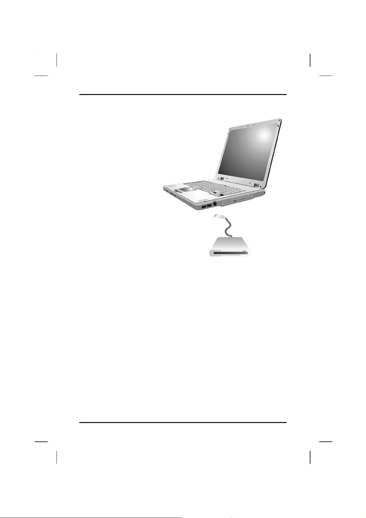
Connecting the Floppy Disk Drive
Your notebook computer
comes with a USB port
1.44 MB floppy disk drive
(FDD is optional). The
FDD is “hot pluggable,” so
you do not have to power
down the notebook to
connect it.
Disk Drives
Floppy Disk Drive
USB connecto
Your computer comes with several components for reading and writing
(recording) information.
Floppy Disk Drive
The floppy disk drive provides a convenient way of storing and transferring
small files. The disk drive uses standard 3.5-inch, 1.44 MB disks. To use
the disk drive, insert a disk (label side up) into the drive slot and slide it all
the way in. To eject the disk from the drive, press the eject button. When
the computer is reading from or writing to a disk, the disk indicator light will
flash. Do not try to eject the disk when this light is active or you may lose
data.
Hard Disk Drive
The hard disk provides high-capacity storage and fast access. Windows
and most programs are stored here. Your notebook identifies the hard disk
drive as drive C.
23
Page 28
Chapter 2 — Getting Started
The CD-ROM, DVD-ROM, Combo Drive, or DVD±RW
Your computer comes with a pre-installed CD-ROM, DVD-ROM, Combo
drive or DVD±RW. The CD-ROM drive is a read-only drive. It cannot be used
to write data to a recordable CD. The CD-ROM drive can read data from CDs,
including audio or video CDs. The CD-RW can perform these same functions,
as well as record information to writeable CD's. The DVD drive can read both
DVDs and CDs. Your notebook identifies the drive with the letter following the
hard drive letter. If your hard drive is D, then the CD-ROM drive will be E.
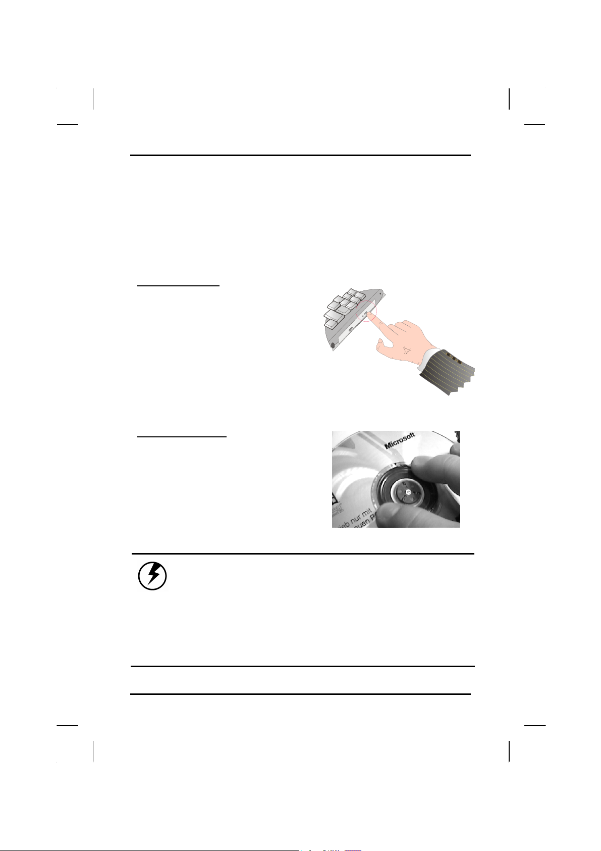
Inserting a Disk
1. Press the button on the front of the
drive to open the disk tray and pull
the tray open.
2. Place the disk on the tray, label
side up.
3. Place the disk on the central
spindle and press gently until the
disk clicks into place.
4. Slide back the tray until it clicks
shut.
Removing a Disk
1. Make sure the computer is not
accessing the CD-ROM drive.
2. Press the eject button and pull the
tray all the way out.
3. Pick up the CD by the edges and
remove the CD-ROM from the tray.
Push the tray into the computer
until it closes fully.
Warning: When the computer is reading from a CDROM/CD-RW/DVD, the indicator light for the CD-ROM
will flash on. Do not attempt to remove a disk
while this light is active.
The lock is located to the left of the eject
button. In locked mode, the drive will stop if the
eject button is accidentally pressed when reading a
CD. When this happens, please unlock the drive,
press eject and push the tray back into the
computer before reading again.
24
Page 29
Getting Started — The CD-ROM, DVD-ROM, Combo Drive, or DVD±RW
Precautions for Handling CD-ROM Discs
Keep these precautions in mind when handling CD-ROM discs.
• Always hold the disc by the edges; avoid touching the surface of
the disc.
• Use a clean, dry, cloth to remove dust, smudges, or fingerprints.
Wipe from the center outward.
• Do not write on the surface of the disc.
• Extremes in temperature may damage discs. Store discs in a
cool dry place.
• Do not use benzene, thinners, or cleaners with detergent. Only
use CD-ROM cleaning kits.
• Do not bend or drop the discs.
• Do not place objects on top of discs.
Warning: Do not insert any
foreign objects into the
disc tray. Do not force
the tray to open or close
manually. When not in use,
keep the tray closed to
prevent dust or dirt from
entering the drive unit.
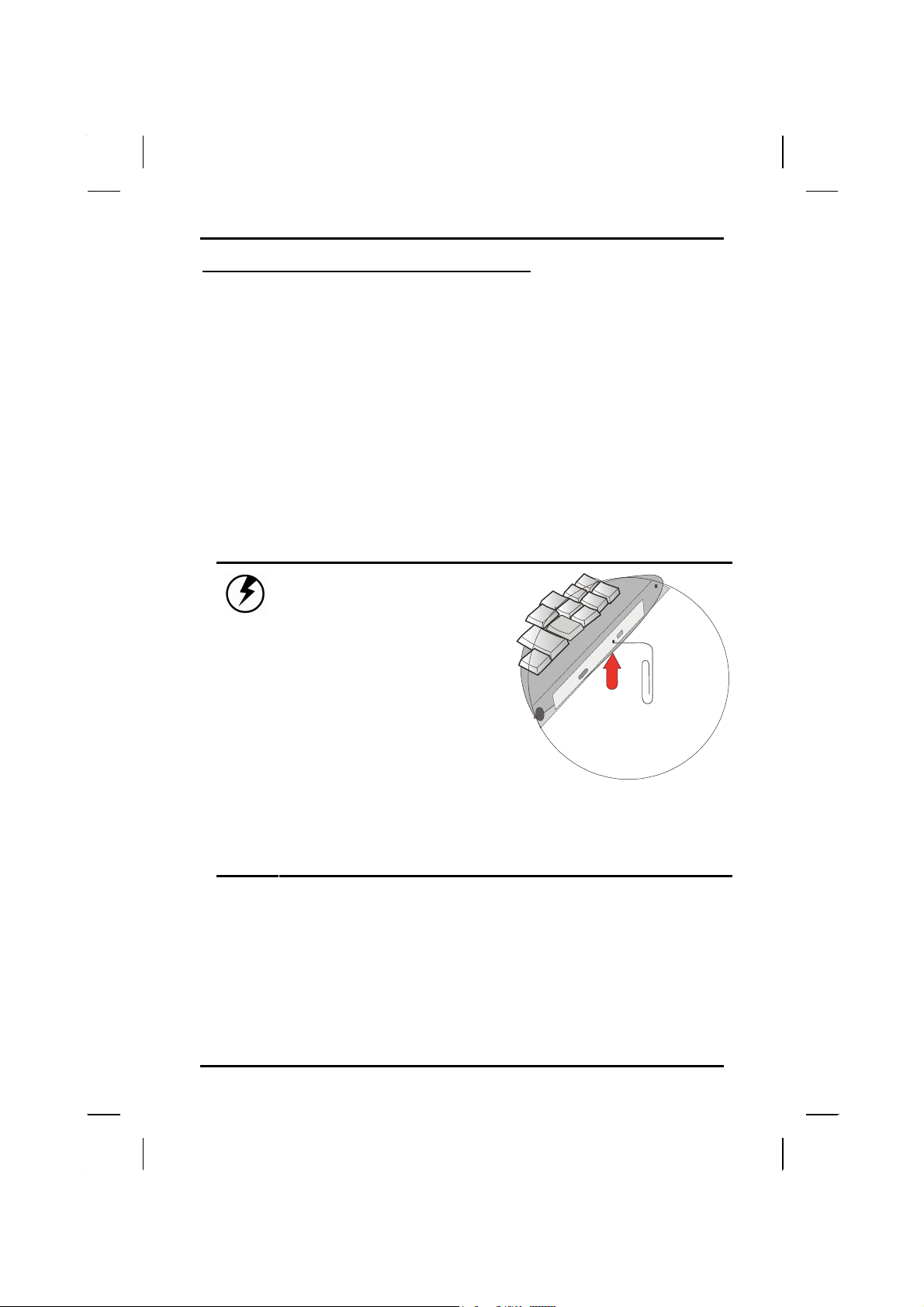
If you experience
difficulty when removing a
CD disc, stretch a paper
clip (or use a pin or a
thin metal rod) and insert
it into the emergency
eject hole located on the
front panel:
The CD disk tray should eject immediately. This
procedure can also be used to remove a CD from the
drive when the notebook is powered off.
25
Page 30
Chapter 2 — Getting Started
Connecting the Printer
To connect a printer to your notebook via the USB port, use the optional
USB to printer adapter cable.
Note: Before use, you must install the driver for the
adapter cable.
The PCMCIA Card Slot
The PC card slot can be used as an interface between your computer and
a variety of communications devices, such as network adapters, SCSI
adapters, fax/modems, or provide additional data storage capacity. Your
computer's PC card slot
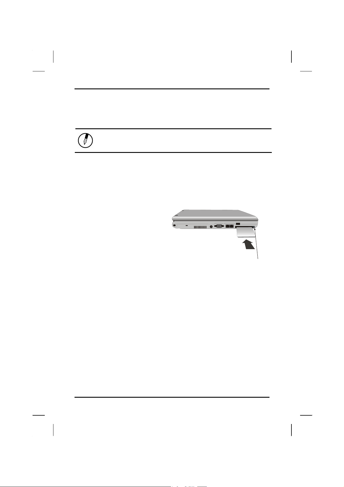
Installing a Card
1. The top side of a PCMCIA
card is usually identified with
a label. Insert the card into
the slot with the label side up
and the edge with pinhole
contacts going in first.
2. Insert the card into the slot.
You will feel some resistance
as the card slides into the
back of the slot.
3. PCMCIA cards require drivers, or a program that allows the
operating system to use a specific device. Many drivers are
included with Windows, but if not, you will be prompted to install
the driver included with your card.
supports PCMCIA Type II and 32-bit CardBus.
Slide the card
into the slot.
Push the button to
eject the card.
Removing a Card
1. If a card is in use, you must shut down the card before removing it.
Or you can click the PCMCIA icon on the right side of the taskbar,
then click Stop.
2. Select the PCMCIA card in the next window, and click “OK”.
3. Press the eject button on the card slot to release the button.
4. Press again to release the card.
26
Page 31
Getting Started — Memory
Memory
Adding memory allows the computer to operate faster, handle more tasks
simultaneously, and work more smoothly with large files. Users who
increase memory demands - by adding additional programs, for example may notice a slowdown in operating speed, and wish to increase memory.
The notebook includes a memory card slot for adding additional memory.
Note: Use only 1-inch SODIMM modules.
Calculate memory size by adding the size of the memory module to the two
memory slots. For example: 256 MB (module) + 256 MB (module) = 512
MB Total
Replacing a Memory Card
Warning: Memory modules can be easily damaged by
static electricity. Leave the module inside its
static-proof bag until it is ready for installation.
Removing a Memory Card
1. Turn off the computer and disconnect the AC adapter. Turn the
computer upside down and lay it on a flat surface.
2. Carefully remove the two RAM compartment cover screws and
remove the RAM compartment cover.
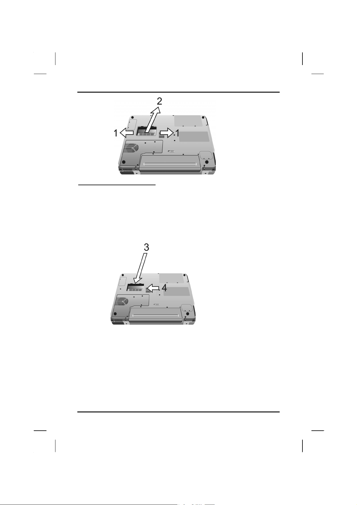
3. Gently pull tabbed latched in the direction of the arrows (1). The
card will pop up slightly.
4. Pull upwards on the card and then slide the card out (2).
27
Page 32
Chapter 2 — Getting Started
Inserting a Memory Card
1. Hold the memory card by its edges with the edge-connector
side towards the slot.
2. Hold the card at a shallow angle (about 25 degrees) and insert
the edge connector into the connector slot (3). The “gold teeth”
of the edge connector should no longer be visible when the
card is fully inserted.
3. Press the card downwards so that it is flat inside the
compartment (4). You may hear an audible click as the latches
of the connector lock the card in place.
4. Replace the RAM compartment cover and secure it with the two
screws.
Your notebook computer will automatically detect the change in RAM
capacity when it restarts.
28
Page 33
Getting Started — The Graphics System
The Graphics System
Your computer has a high-performance graphics system, which can easily
handle the demands of today's multimedia computing.
Screen Controls
Brightness
Function keys can increase or decrease the brightness of the monitor.
• <Fn> + <F6> decreases the LCD panel brightness
• <Fn> + <F7> increases the LCD panel brightness
Resolution
1. Click My Computer/Control Panel/Display/Settings. Click the
Settings tab. The dialog box indicates the monitor resolution.
2. Use the slide bar to adjust the resolution. Normally, you should
use the resolution the LCD or monitor was designed for.
Note: Using a lower resolution than the screen was
designed for will reduce the area of the display.
Using the computer in DOS mode may produce the same
effect, because it uses a 640 by 480 resolution by
default. You can stretch these low resolution
displays to full screen size by selecting either the
Expanded Display or Display Expansion Mode features
in the BIOS utility. However, the stretching may
cause distortion, especially to fonts.
High Resolution with an external monitor
Higher resolution modes may be used, as long as the monitor supports
them.
Connecting to an External Monitor
The notebook has a VGA monitor port to connect your computer to an
external monitor.
Using the VGA monitor port
1. Locate the 15-pin VGA monitor port on the left side of your
notebook and connect the video signal cable from the external
monitor (or the VGA adapter) to the monitor port.
2. Connect the power cable from the external monitor to a power
outlet and turn on the monitor.
3. On your notebook, click the right touchpad button on the
29
Page 34
Chapter 2 — Getting Started
Windows desktop to open the desktop menu. Click Properties to
open the Display Properties window.
4. In the Display Properties window, click Advanced in the Settings
tab. Click the Display Modes tab.
5. Under Driver mode, you can select the appropriate options to
change the display to an external monitor.
6. Adjustments to screen resolution and color depth can also be
made in this dialog box.
Dual Displays
With Windows system, you may use an external monitor simultaneously
with your notebook’s LCD. You may also use the external monitor only and
disable the LCD or only use the LCD. To do this you may first need to
enable the multiple display settings in Windows .
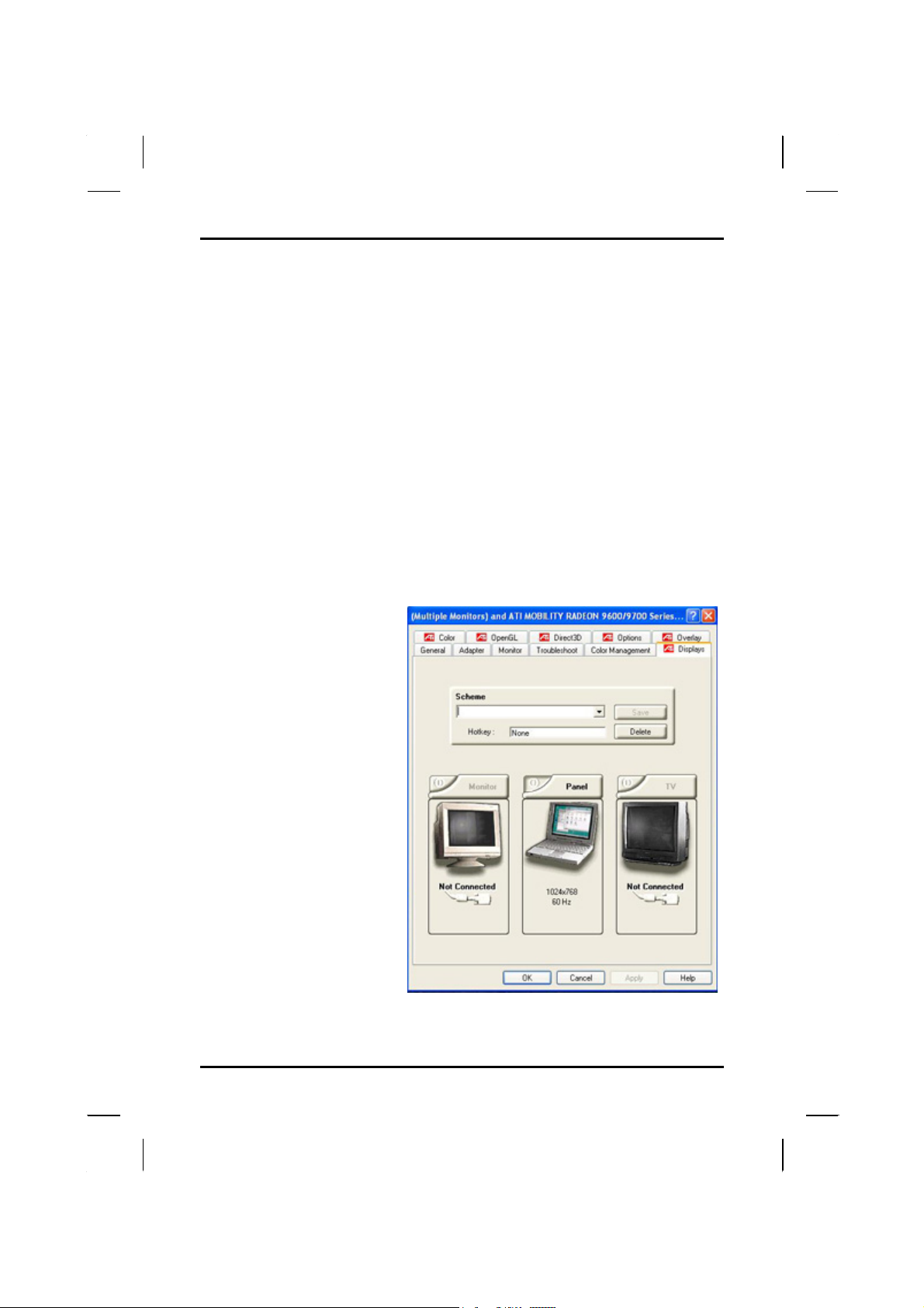
1. Open the Control
Panel.
2. Double-click Display.
The Display Properties
window opens.
3. Click the Settings tab.
4. Click the Advanced
button.
5. Click the ATI Display
tab. The screen shown
at the right appears.
30
Page 35
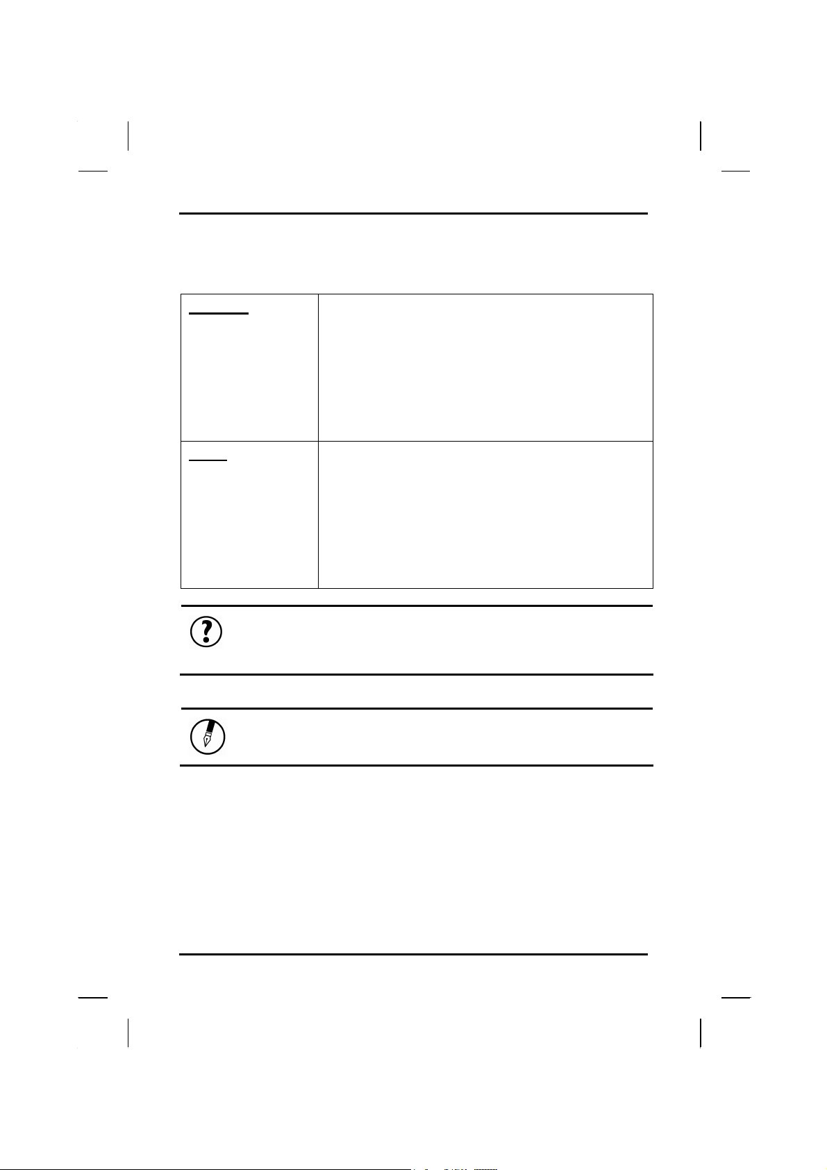
These options are described below
Standard
Clone
Tip: To ensure trouble-free video output, the first
time you use an external monitor, change the output in
the Display Properties dialog box. After successfully
switching modes, you may use the video function keys.
In Display Combination, there are two options
available: VGA1 or LCD2. You can choose which
device to apply as the Primary display. VGA1 is the
default value for Primary if an external CRT is
available. If an external CRT is not connected to the
notebook, only LCD2 is available.
In Single mode, the video display hot key
combination is available—you can cycle the video
output by pressing the Fn + F2 keys.
In Display Combination, there is no Primary
display option available. Only LCD2 is available as
Secondary display even when an external CRT is
connected.
In Mirror mode, the video display hot key
combination is available—you can cycle the video
output by pressing the Fn + F2 keys.
If the external CRT is connected, the display on the
LCD and the CRT is the same.
Getting Started — Dual Displays
.
Note: Light or dark dots may appear on the LCD due to
technical limitations of LCD manufacturing. This will
not effect normal operation of the LCD.
31
Page 36
Chapter 2 — Getting Started
Communication Components
This system provides powerful communication functions, including built-in
MiniPCI 802.11g and PCMCIA card slot.
Fax/Modem
A phone jack on the left side of the computer allows you to connect to the
Internet to send and receive data. When used with fax software, it can be
used as a fax. When using this function, first plug the phone cord into the
jack.
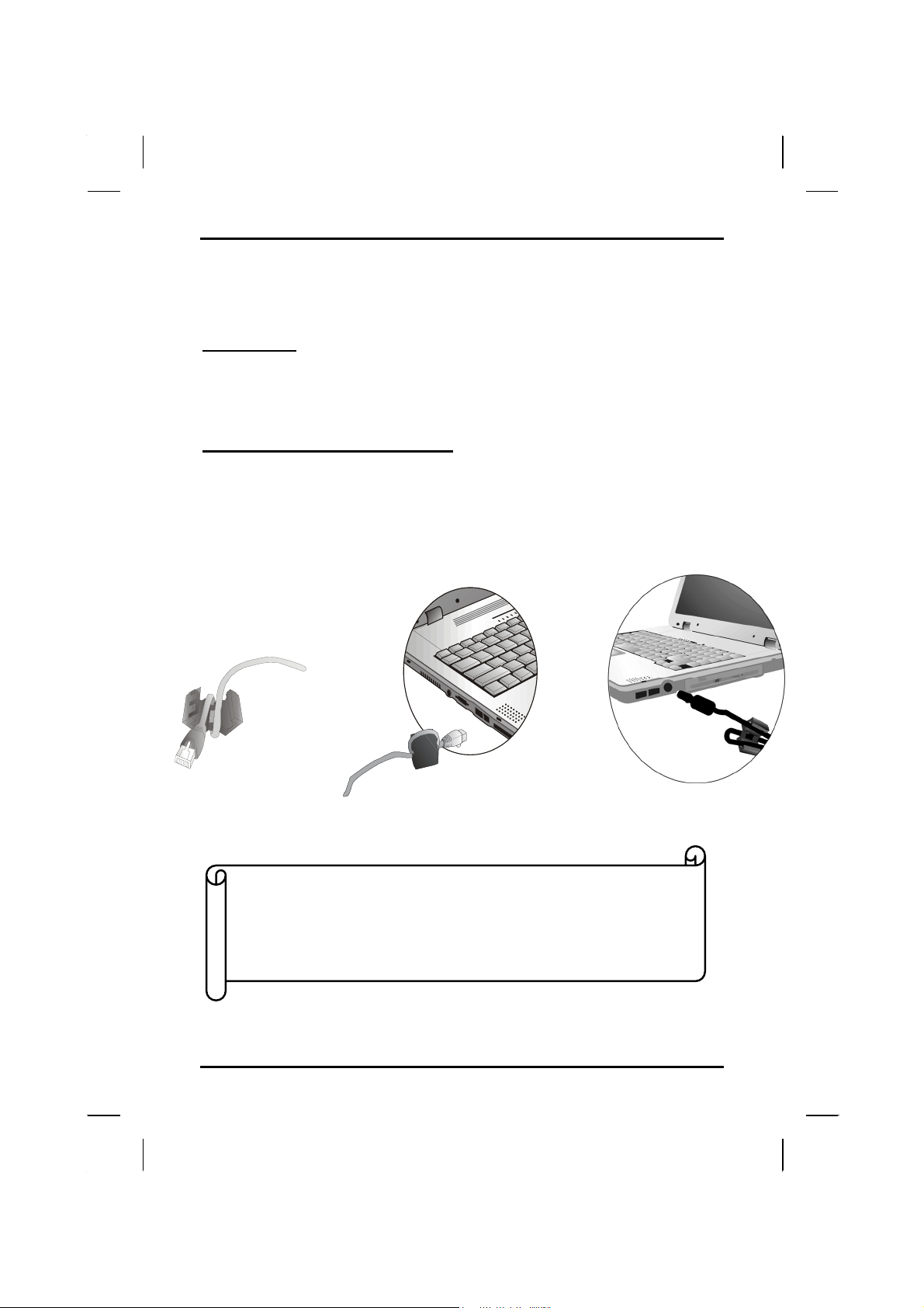
Anti-electromagnetic wave clip
To eliminate electromagnetic waves, it is strongly recommended that you
thread the CRT cable, S-video cable and phone cord through the clip
provided as shown below when using peripherals, fax/modem jack or
connecting to a phone line.
Attention:
When using the data communications function, please do
not plug the phone cord into the ISDN or PBX jack to
avoid an electrical surge that will cause the MDC
module to burn.
32
Page 37
Getting Started — Information about the Wireless LAN button
Information about the Wireless LAN button
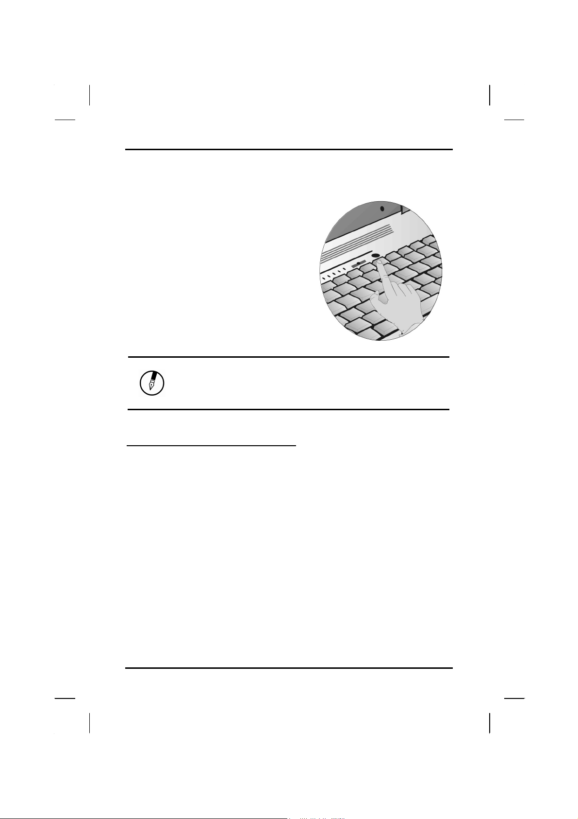
Wireless LAN button
Even when a Wireless LAN module has
not been built-in to your computer, the
Wireless LAN indicator lights and remains
active when you turn on the Wireless LAN
button near the power button of your
computer.
If Wireless LAN module has been built-in,
your notebook will search for the device
and will display an icon on the Windows
task bar.
Note: If your Notebook does not include a built-in
Wireless LAN module, please turn off the Wireless
LAN button. If turned on, the indicator lights and
remains active even if no wireless LAN is present.
Built-in Wireless Local Area Network
The built-in Wireless Local Area Network (WLAN) interface card can
provide a quick access without using cables for the connection to the
network equipments. The interface card adopts the IEEE 802.11 protocol
and uses the 2.4 GHz ISM electric wave frequency band as the
transmission interface to set up the communications between the host
computer and other computers.
The way of processing communications through the WLAN interface card is
the same as that through Ethernet interface card. The “Configuration Tool”
is a Window application program. If users have a computer equipped with
the WLAN interface card, then users can use it to set up the interface card
and show the current configuration and status.
Note: Contact your distributor for the information of upgrading the
wireless local area network.
33
Page 38

Chapter 2 — Getting Started
DGT Warning
Article 14
Without permission, any company, firm or user
shall not alter the frequency, increase the
power, or change the characteristics and
functions of the original design of the
certified lower power frequency electric
machinery.
Article 17
The application of low power frequency electric
machineries shall not affect the navigation
safety nor interfere a legal communication, if
an interference is found, the service will be
suspended until improvement is made and the
interference no longer exists.
The foregoing legal communication refers to the
wireless telecommunication operated according
to the telecommunications laws and regulations.
The low power frequency electric machinery
should be able to tolerate the interference of
the electric wave radiation electric
machineries and equipments for legal
communications or industrial and scientific
applications.
34
Page 39

CChhaapptteerr 33
Maakkiinngg
M
CCoonnnneeccttiioonnss
Page 40
Chapter 3 — Making Connections
Making Connections
Your computer is equipped with a full array of ports and connectors,
including standard input/output (I/O) ports for quickly and easily adding
peripheral devices such as printers, keyboards, and mice. Refer to
documentation included with individual devices for details on
connecting these devices to your computer. Along with the standard
ports found on most computers, your computer also includes IEEE
1394 ports, modem and LAN ports, offering advanced communications
technology.
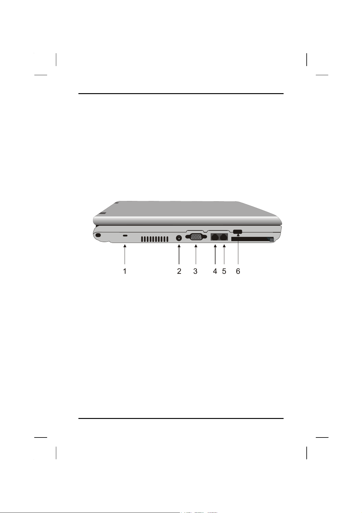
Left Side Connectors
1. Kensington Lock
Your computer includes a Kensington lock hole to be used with a
standard Kensington lock. You can connect the notebook to a large
object with the Kensington lock to prevent theft of your notebook. See
the documentation that comes with your Kensington lock for more
information.
2. DC-in Jack
Connect the DC power cable from the AC adapter to this jack.
3. VGA Out (External Video) Port
The 15-pin VGA port can be used to connect your computer to an
external monitor. (See the Graphics System in chapter 2 for more
information).
36
Page 41
Making Connections — Right Side Connectors
4. LAN RJ-45 Jack
With the built-in Ethernet LAN combo, you can make LAN connections
without installing PC cards. Connection speed is 10/100 Mbps. When
using the LAN function, wrap your LAN cable around the EMI ferrite
suppression box to inhibit electromagnetic interference.
5. Fax/modem RJ-11 Jack
The fax/modem can transmit data using the 56 Kbps V.90 protocol,
and send and receive faxes at 14.4 Kbps. In some countries, local
regulations may not permit the use of the fax/modem designed for this
system. In this case, you may use a PCMCIA modem.
6. USB (Universal Serial Bus) Ports
The Universal Serial Bus (USB) is the latest standard for attaching
monitors, input devices, scanners, and other devices to a PC. USB
devices can be chained together on a single cable.
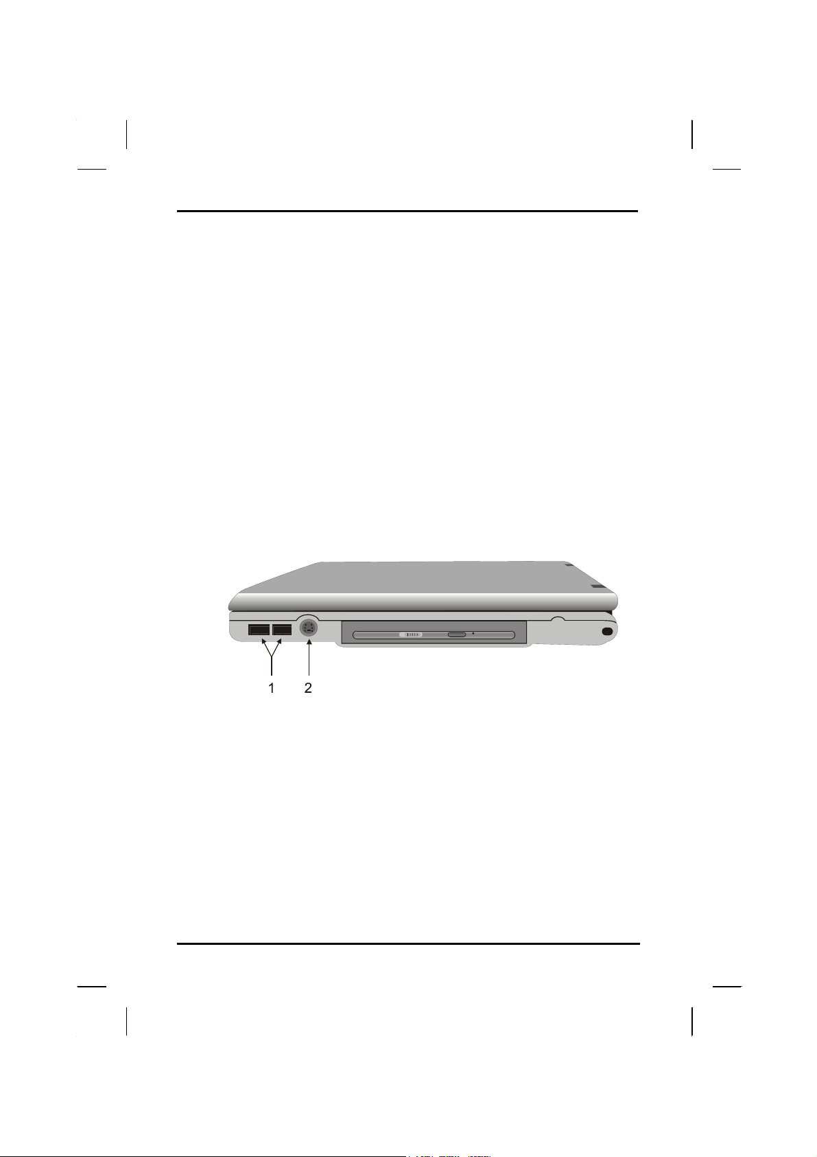
Right Side Connectors
1. USB (Universal Serial Bus) Ports
The Universal Serial Bus (USB) is the latest standard for attaching
monitors, input devices, scanners, and other devices to a PC. USB
devices can be chained together on a single cable.
2. S-Video Port
S-Video technology provides sharper video image on a video or
television device than traditional TV-out connections, provided your
video display device supports S-Video output.
37
Page 42
Chapter 3 — Making Connections
Warning: Plug your modem into an analog telephone
jack only. Most homes use analog lines.
Do not use digital lines, such as the PBX
and ISDN systems found in many offices.
Digital lines may damage your modem.
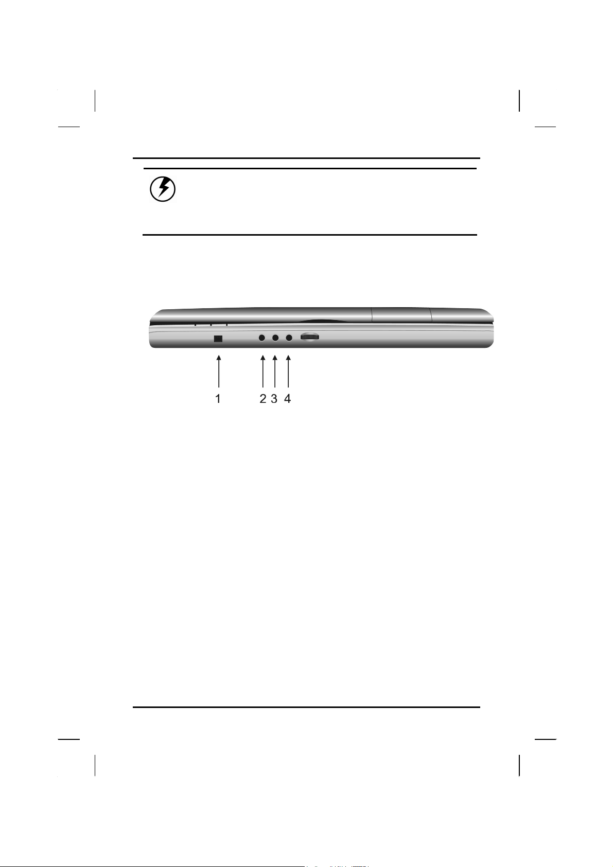
Front Side Connectors
1. IEEE 1394 Port (4-pin)
The IEEE 1394 port is able to transfer large amounts of data at high
speed. Because of this ability, the IEEE 1394 port is often used with
multimedia devices, such as video cameras. However, a variety of
devices that support the IEEE 1394 standard can be connected to this
port.
2. SPDIF Jack
Connect a SPDIF speakers to this jack to listen audio sound.
3. Audio-out Jack
Connect a stereo headset or external speakers to this jack to listen to
multimedia.
4. Microphone-in Jack
Connect a microphone this jack to record audio.
38
Page 43

SSyysstteem
m SSoofftt
CChhaapptteerr 44
waarree
w
Page 44

Chapter 4 — System Software
System Software
Software List
Operating System
Your hard drive already contains all the software you need to operate
the computer.
Audio and Video Drivers
These utility programs and drivers are included for the PC Card drive,
the sound system, and the graphics sub-system.
DVD Player Application
The DVD player application will let you watch DVD movies on your
notebook (for DVD-ROM/DVD-RW module only).
40
Page 45

System Software — System Recovery
System Recovery
Before you start
Your system includes two Recovery CD-ROMs. Follow the steps in the
appropriate section below to reinstall the operating system, the system
software, or add a new hard disk.
• The factory has pre-partitioned your system's hard disk, so you
may directly install the system software; however, if you change
a new hard disk, you must first partition it.
• If you reinstall your operating system, all of the data
originally on the hard disk will be overwritten. Before
reinstalling the operating system, carefully backup any
important data.
• Your system is shipped with two different Recovery CD-ROMs.
Before reinstalling, note the CD-ROM labels.
Caution: When you re-install operating system by
Recovery CD for Windows, we STRONGLY recommend
connecting the AC adapter( do NOT use battery
alone )to avoid warning message.
41
Page 46
Chapter 4 — System Software
Recovering Windows and Original Software
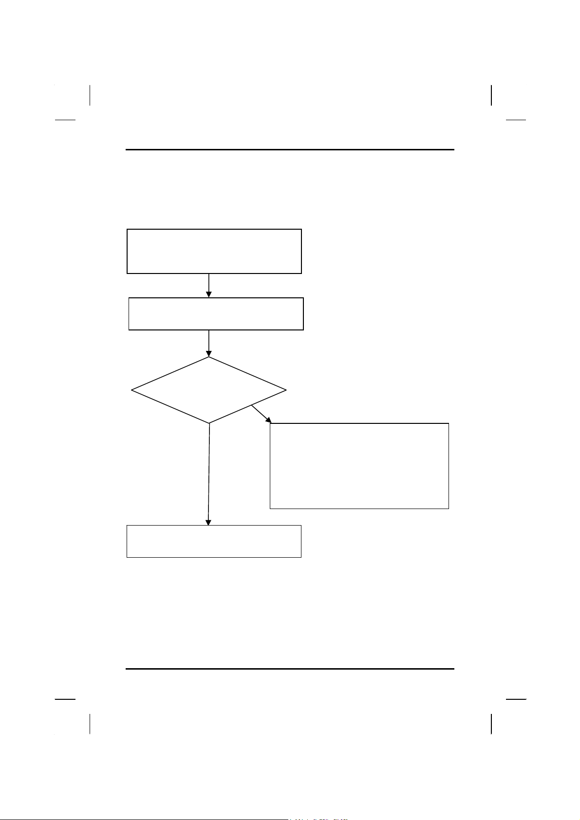
If your Windows operating system is lost or damaged, use the Recovery
CD (Windows).
Enter BIOS setup.
Set first boot device to “CD-ROM.”
(See Chapter 6: BIOS Settings.)
Put the Windows Recovery CD into the CDROM drive and reboot the computer.
Hard disk partitioned?
Follow the instructions in the sections below:
YES.
Follow steps under Recovering Windows.
NO
• Partitioning the hard drive
• Recovering Windows
• Creating a Suspend-to-Disk Partition
(Windows 98SE only)
• Recovering original software
42
Page 47
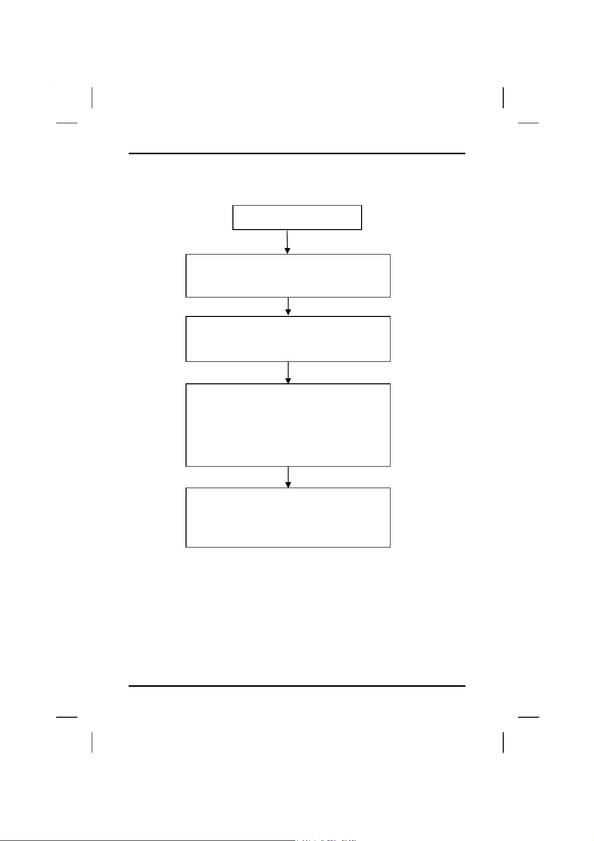
Partitioning the Hard Drive
Hard drive is not partitioned.
When the Microsoft Windows startup menu
appears, select (2) Go to MS-DOS PROMPT.
Press Enter to repartition your hard disk.
At the A:\ prompt, type fdisk and press Enter.
Note: If your computer is set to boot from the CDROM drive, “A” refers to your CD-ROM.
If you see the message: “Do you wish to enable
large disk support (Y/N),” Select “Y.”
On the first screen select “Create DOS partition or
logical DOS drive.”
On the next screen select “Create Primary DOS
partition.” This will create the largest possible
partition as the C drive.
System Software — System Recovery
After completing disk partitioning, press ESC to
exit fdisk.
Press <Alt>, <Ctrl>, and <Del> to reboot your
computer.
Follow steps under Recovering Windows.
43
Page 48
Chapter 4 — System Software
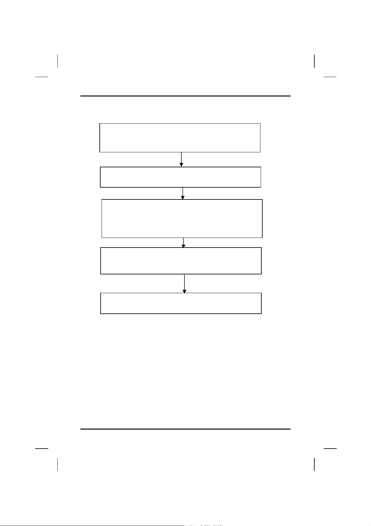
Windows XP Reinstallation
Enter BIOS setup.
Set first boot device to “CD-ROM.”
(See Chapter 6: BIOS Settings.)
Put the Recovery CD for Windows XP Disc#1 into the
CD-ROM drive and reboot the computer.
When the Microsoft Windows XP Menu appears, choose option 1:
Recovery CD for Windows XP. When prompted, insert the
Disc#2. It will take approximately five minutes to complete the
installation. Remove the CD-ROM from the drive when the
installation is complete.
Press <Alt>, <Ctrl>, and <Del> to reboot the computer. Enter the
BIOS Setup Utility and select Boot priority. Reset the boot priority
to either A: or C:
While starting Windows, reenter the Windows information as
prompted.
44
Page 49

CChhaapptteerr 55
PPoow
Maannaaggee
M
weerr
meenntt
m
Page 50
Chapter 5 — Power Management
Power Management
Battery Calibration
The first time you use a battery, you should calibrate it. The calibration
process empties and charges the battery one time. This allows the
Windows battery gauge to accurately monitor battery status. To
calibrate a battery, follow these steps:
1. Plug in the AC adapter.
2. Restart the computer and when the startup screen appears,
press Del key to enter the BIOS Setup Utility.
3. In the BIOS Setup Utility, select Advanced Setup , choose Start
Battery Learning, then press <Enter>.
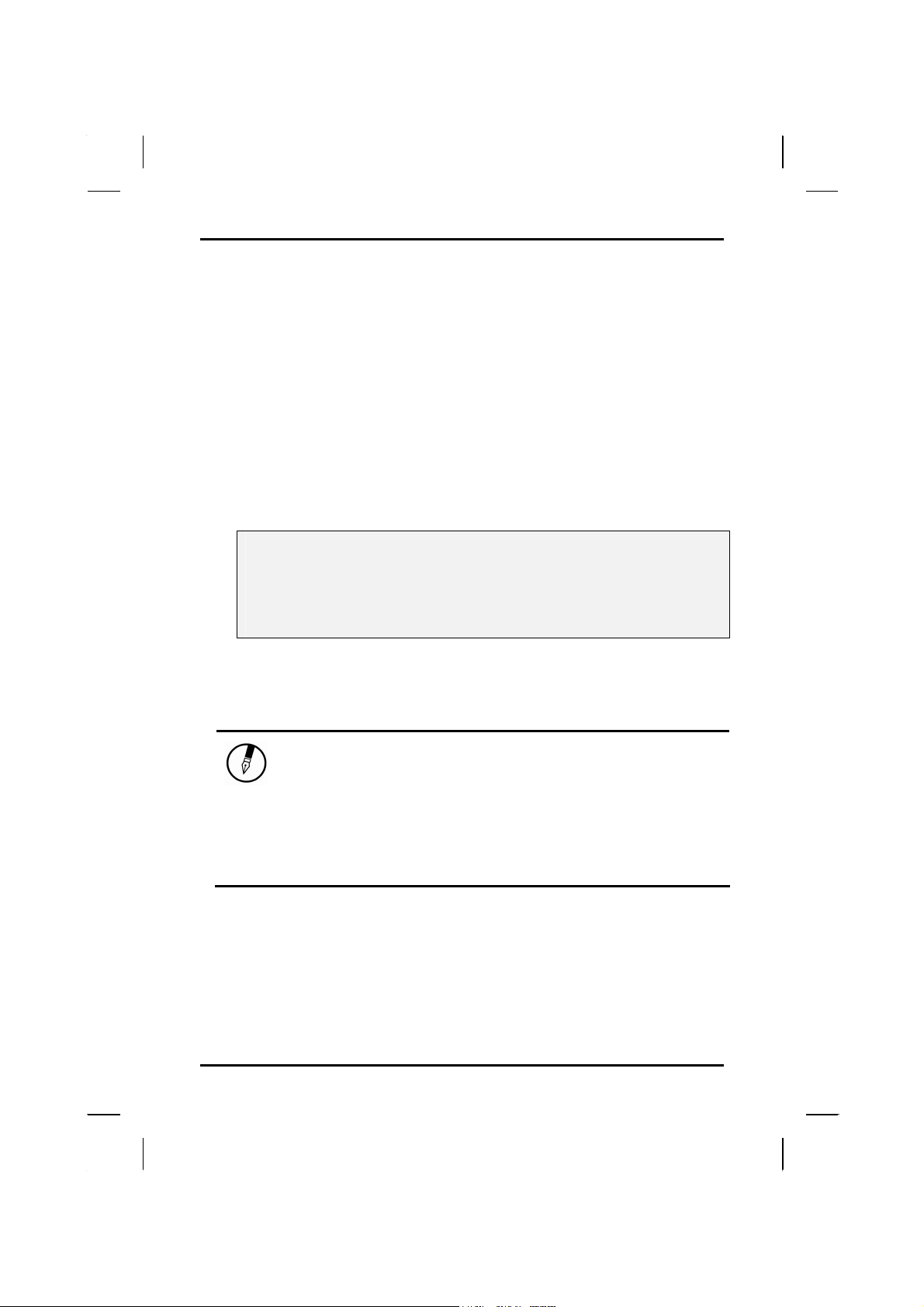
Please make sure that AC adapter & Battery are present?
Would you to do battery learning?
[OK]
[Cancel]
4. Select OK. at the above Battery Auto Calibration dialog to begin
the battery calibration. Please press [Y] to continue.
Battery Calibration will take from 10 to 16 hours, depending on how
much power the battery may already contain.
Note: For optimum performance, we recommend
calibrating the battery again every three months.
Each time you charge and discharge a battery, it
loses a tiny part of its storage capacity, so that,
over time, it will store less than its potential
charge. Similarly, if you do not use the battery
for a few days, it will slowly self-discharge, and
when it is recharged, it will hold less than 100%
of the potential charge.
46
Page 51
Power Management — Power Management
Monitoring Battery Power
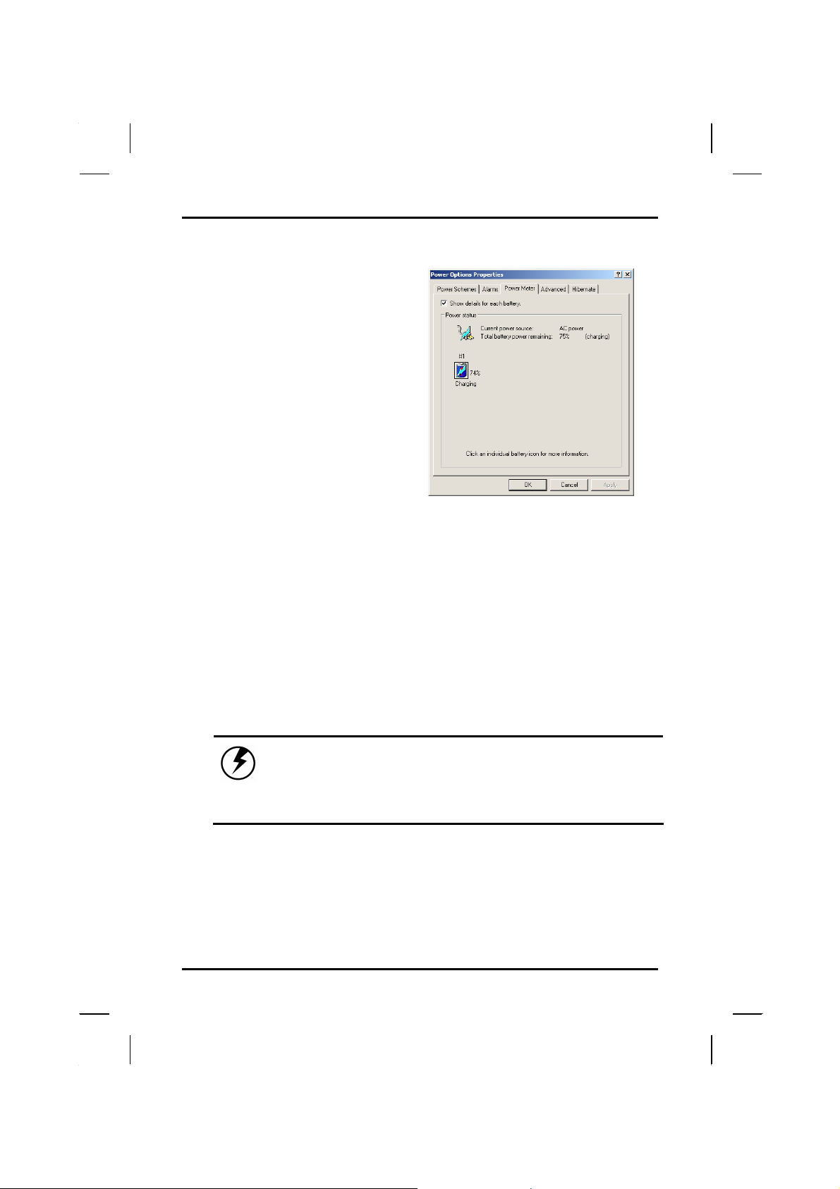
There are two ways to
monitor how much power the
battery has left.
1. Click Start / Settings /
Control Panel / Power
Options ; then click
Power Meter.
2. Moving the cursor to the
battery icon on the
taskbar is the simplest
way to check on battery
power status.
If you do not see the battery icon, enable it in Start / Settings /
Control Panel / Power Options . Choose the Advanced tab and click
“Always show icon on the taskbar.”
Low Battery Alarms
How your computer responds to a low battery condition is set under
Start / Settings / Control Panel / Power Options / Alarms.
Two different power alarms can be enabled or disabled: the Low
Battery Alarm, and the Critical Battery Alarm. Use the slide bar to set
the power level at which the alarms are activated. Click on the Alarm
Action button to choose whether the alarm sounds, displays a
message, or both.
Warning: When battery power is low, the battery
indicator will flash red, and the alarm will beep
or display a warning on your screen. Take
immediate action, such as saving files or
connecting to the AC adapter, or data may be lost.
When the computer alerts you that the battery is low, immediately do
one of the following:
• Connect the AC power adapter
• Save your work, and suspend to disk <Fn> + <F3>
• Save your work, then select Shut Down from the Start menu
47
Page 52
Chapter 5 — Power Management
• Turn off or suspend the computer and replace the discharged
battery with a charged battery (See Battery Charging below).
Do not restart the computer until you have connected to an AC
adapter, or replaced the discharged battery with a charged battery.
Battery Charging
When you use the AC adapter to connect your Notebook to a power
outlet, the internal battery will automatically begin to recharge. While
the battery is charging, the Battery Charge icon on the Indicator panel
will be active after 6~12 seconds. When the battery is fully charged,
the Battery Charge icon will turn to green.
If your computer is turned off, a fully discharged battery will take about
3.5 hours to recharge. If your computer is turned on and is not in
suspend mode, it twill take about 6~13 hours to recharge the battery.
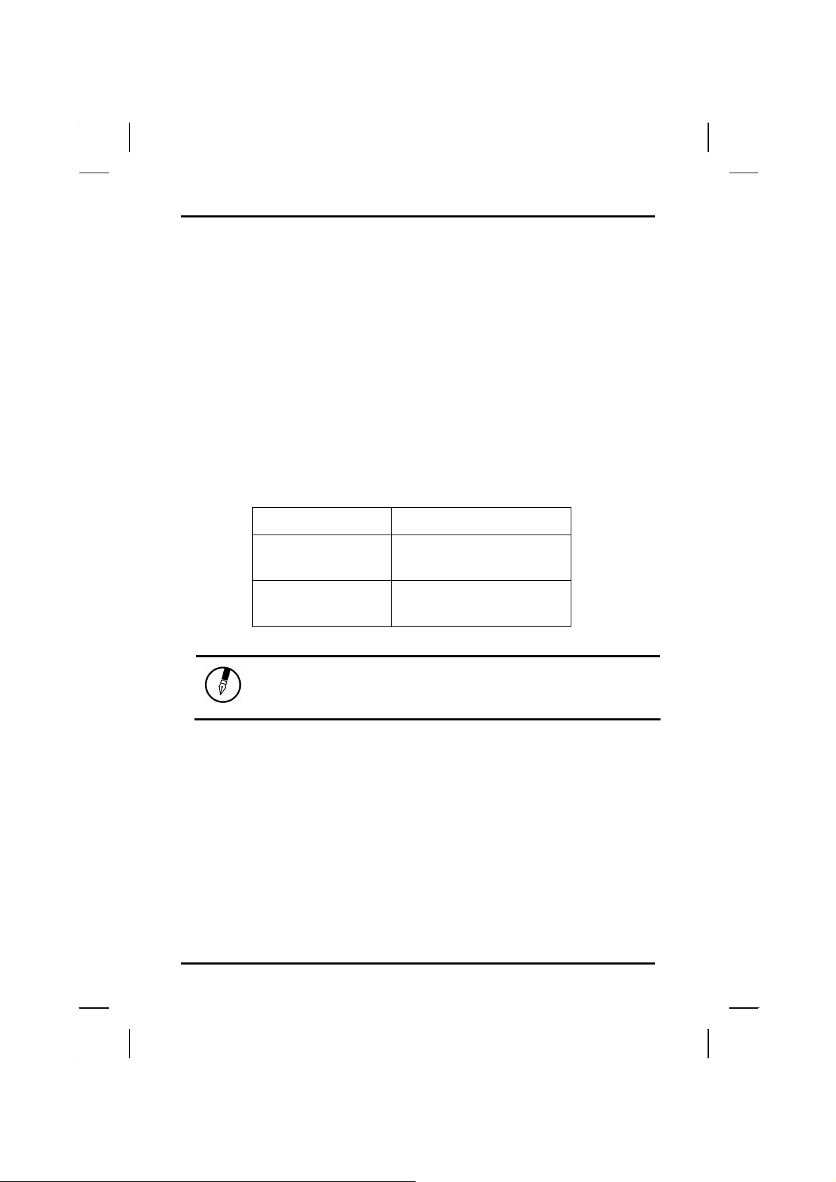
Refer to the following table:
Charging
System On
System Off
(suspend-to-disc)
Note: A fully charged Li-Ion battery can run the
Notebook for approximately 3 hours. (According to
Battery Mark benchmark tests)
6~13 hours
3.5 hours
Power Saving Modes
Adjust the default power management settings in the Power Options/
Advanced dialog box in the Control panel. The Power Options
Properties dialog box allows you to set different actions to take when
the computer is left idle for a certain amount of time.
Suspend Mode
There are several possible settings for suspend mode, which can be
selected in the Power Management dialog box: You may have the
48
Page 53

Power Management — Power Saving Modes
notebook standby, hibernate, or you can power off the computer
altogether.
Standby
Hibernate
Power Off
All devices are powered up and in suspend mode .
Suspend to Disk is similar to turning off the computer,
except that the current state of the computer is copied
to the hard disk as a special file. When the computer
returns from suspend mode, the desktop appears
with the same files and programs open as when the
computer was suspended. Suspend to Disk is very
useful when you don't want to take the time to shut
down all open programs one by one to shut off the
computer, only to have to open the same programs
and files the next time you use the computer. This
mode is also called hibernation mode.
Suspend-to-disk Partition/Suspend-to-disk File
Suspend to Disk file will be saved by Windows to the
hard disk. The size of the file will correspond to the
amount of system memory. Please make sure there is
enough space on the hard disk.
System is shutdown.
Initiating Suspend Mode
There are four ways to initiate suspend mode. The settings can be
adjusted in the Power Management dialog box:
• The computer will automatically enter suspend mode when not
used for a set period of time.
• Selecting the Stand by button in the Shut Down Windows dialog
box.
• Closing the screen cover (assuming no external monitor has
been connected).
• Pressing the power button (if enabled in power settings).
• Pressing the suspend function key <Fn> + <F3>.
49
Page 54

Chapter 5 — Power Management
Using the BIOS Utility for Power Management
With Windows running in ACPI mode, power can be controlled
through the Power Management dialog box only. With operating
systems that use ACPI power management, BIOS power settings
have no effect.
Power Button Settings
The function of the power button can be set to Shutdown or Standby in
the Power Management Properties dialog box in the Windows Control
Panel. However, holding the power button down for more than four
seconds will force a power off while operating under any situation,
resulting in the loss of any unsaved information.
Power Saving Tips
• Avoid operating the fax/modem, or audio and video applications
when using battery power. Operating a fax modem, video, or
audio equipment or turning on the Wireless LAN power button
increases the computer's power requirements.
• Decreasing monitor brightness can also save power. Decrease
brightness by pushing <Fn> + <F6>. Increase it by pushing
<Fn> + <F7>.
When to Replace the Battery
Over time, the battery's capacity gradually decreases. We recommend
that you replace your battery when you notice that it begins to store
significantly less charge.
50
Page 55
Power Management — Heat Considerations
Changing the Battery
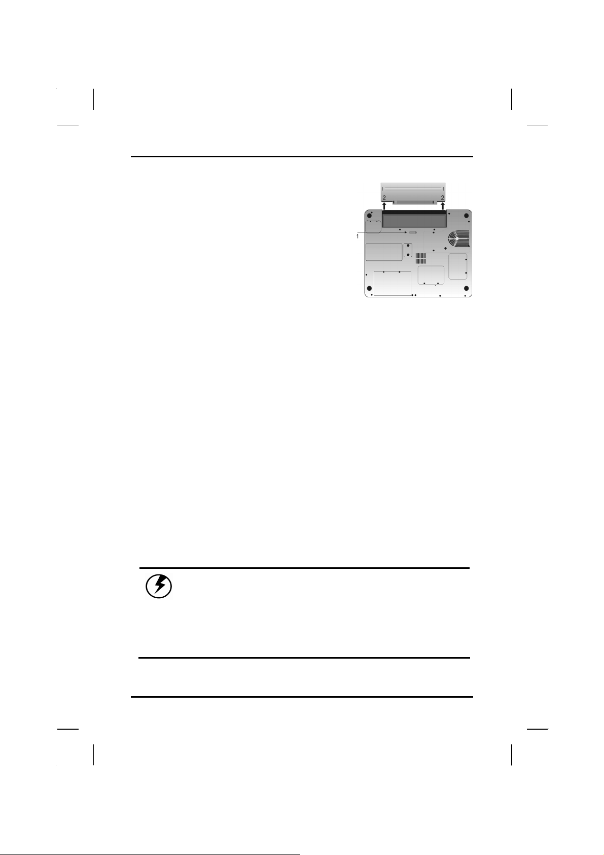
Change the main battery pack as
follows:
1. Turn off the computer.
2. Close the screen cover and turn the
computer over.
3. Slide the side battery latch (1) away
from the battery. Continue to hold it
until the battery is removed.
4. Push in the latch on the battery (2)
while lifting the battery out of the
compartment. Remove the battery.
5. Make sure the replacement battery is properly orientated. Slide
back the side battery latch (1) then insert the battery into the
battery compartment. Check that the latch locks back into
position.
Heat Considerations
The computer's processor has been specially designed to consume
little power, and generates very little heat. However, working in a hot
environment, or working for long periods may raise the temperature.
Your computer takes the following steps to lower temperature:
1. The cooling fan will automatically turn on. You may feel air coming
from a vent at the left side when this happens.
2. If the temperature continues to rise, processor activity will be
reduced. You may notice a slight loss of performance when this
happens.
Warning:If the operating temperature exceeds 35 oC,
the system will shut down to prevent the
heat from damaging the computer’s
infrastructure. When the computer cools to
a normal temperature you can restart the
system. The higher the temperature of the
environment, the longer the period the
computer will need to cool down.
51
Page 56

Chapter 5 — Power Management
52
Page 57

CChhaapptteerr 66
UUssiinngg tthhee BBIIO
OSS
SSeettuupp UUttiilliittyy
Page 58

Chapter 6 — Using the BIOS Setup Utility
Using the BIOS Setup Utility
Your notebook has a BIOS setup utility which allows you to configure
important system settings, including settings for various optional
functions of the computer. This chapter explains how to use the BIOS
setup utility.
BIOS Setup Menu
The setup uses a menu interface to allow the user to configure their
system. The features are :
Main : Allows the user to specify system time and system date and the
system overview.
Advanced : Allows the user to set advanced settings.
Boot : Allow the user to set the boot sequence.
Security : Allows the user to set the password for system.
Exit : Exit option.
Starting the BIOS Setup Utility
You can only enter the BIOS setup utility as the computer is booting,
that is between the time you turn on the computer and before the
Windows interface appears. If your computer is already on, either
power off or select restart option under windows environment. Restart
it and then press the Del key to enter the setup utility.
Warning: When you use the BIOS setup utility to
configure your computer’s basic settings, we
STRONGLY recommend connecting the AC adapter(do
NOT use battery alone) to avoid warning message.
54
Page 59
Using the BIOS Setup Utility — Navigating and Entering Information in BIOS
Navigating and Entering Information in BIOS
Use the following keys to move between fields and to enter information:
Key Function
Del
ESC
Up, down keys (ÇÈ)
+ or -
Tab Press tab to make a selection
F1 General Help
F10 Press F10 to save changes, then exit .
Press Del to start the BIOS utility after
turning on the computer.
Press Esc to exit any section. If you wish to
exit the BIOS utility
without
saving changes,
go to the main men u, then press Esc.
Push the up and down arrow keys to move
among selections, then press Enter to make
a selection.
Use the +, - keys to modify a field. Use + to
increase a value, such as a date or number,
and - to decrease it. For other types of
choices, such as “enabled,” or “disabled,” use
either key to move between c hoices .
Warning: After KBC firmware update is complete,
the system will automatically shut down. Please
unplug all power sources (including AC or
battery) and replug, or use a paper clip to
depress the forced shutdown hole on the bottom
of the computer. This will enable new settings
to be entered.
55
Page 60
Chapter 6 — Using the BIOS Setup Utility
p
The Main Menu
BIOS SETUP UTILITY
Main Advanced Boot Security Exit
System Overview
AMIBIOS
Version : RC.0
Processor
Type:Intel® Pentium®M
1400MH
Speed :1400MHz
System Memory
Size : 256MB
System ime [19:14:50]
System Date [Thu 11/13/2003]
rocessor
Use [ENTER] , [TAB]
Or [SHIFT-TAB] to
select a field.
Use [+] or [-] to
Configure system
Time
Select Screen←→
Select Item↑↓
+- Change Field
Tab Select Field
F1 General Help
F10 Save and Exit
ESC Exit
V02.53 ©Copyright 1985-2002, American Megatrends , Inc.
56
Page 61
Using the BIOS Setup Utility — UAdvanced Menu
Advanced Menu
BIOS SETUP UTILITY
Main Advanced Boot Security Exit
Advanced Setting
Auto DIM function
[Enable]
System can boot from LAN [Enable]
Legacy USB Support
[Enable]
Start Battery Learning
[Enter]
Start FAN Learning
[Enter]
Enables support for
Legacy USB. AUTO
option disables
legacy support if no
USB devices are
connected.
Select Screen←→
Select Item ↑↓
+ - Change option
F1 General Help
F10 Save and Exit
ESC Exit
V02.53 ©Copyright 1985-2002, American Megatrends , Inc.
57
Page 62
Chapter 6 — Using the BIOS Setup Utility
Boot Menu
BIOS SETUP UTILITY
Main Advanced Boot Security Exit
st
Boot Device [Removable Dev.]
1
nd
Boot Device [CD/DVD]
2
rd
Boot Device [HDD]
3
th
Boot Device [Network]
4
Specifies the boot
sequence from the
available devices.
A device enclosed in
parenthesis has been
disabled in the
corresponding type
menu.
Select Screen←→
↑↓Select Item
Enter Go To Sub
Screen
F1 General Help
F10 Save and Exit
ESC Exit
V02.53 ©Copyright 1985-2002, American Megatrends , Inc.
58
Page 63
Using the BIOS Setup Utility — USecurity Menu
g
Security Menu
BIOS SETUP UTILITY
Main Advanced Boot Security Exit
Security Settings
Supervisor Password : Not Installed
User Password : Not Installed
Change Supervisor Password
Change User Password
Install or Chan
password .
Select Screen←→
Select Item↑↓
Enter Change
F1 General Help
F10 Save and Exit
ESC Exit
e the
V02.53 ©Copyright 1985-2002, American Megatrends , Inc.
59
Page 64

Chapter 6 — Using the BIOS Setup Utility
Change Supervisor Password:
Enter new password:
Supervisor Password
Indicates whether a supervisor password has been set. If the
password has been installed, Installed displays. If not, Not Installed
displays.
Change Supervisor Password
Select Change Supervisor Password from the Security Setup menu
and press <Enter>.
Enter New Password:
appears. Type the password and press <Enter>. The screen does not
display the characters entered. Retype the password as prompted and
press <Enter>. If the password confirmation is incorrect, an error
message appears.
Change User Password:
Enter new password:
User Password
Indicates whether a user password has been set. If the password has
been installed, Installed displays. If not, Not Installed displays.
Change User Password
Select Change User Password from the Security Setup menu and
press <Enter>.
60
Page 65

Using the BIOS Setup Utility — U Exit Menu
Enter New Password:
appears. Type the password and press <Enter>. The screen does not
display the characters entered. Retype the password as prompted and
press <Enter>. If the password confirmation is incorrect, an error
message appears.
61
Page 66
Chapter 6 — Using the BIOS Setup Utility
y
Exit Menu
BIOS SETUP UTILITY
Main Advanced Boot Security Exit
Exit Options
Save Changes and Exit
Discard changes and Exit
Discard Changes
Load Optimal Defaults
Load Failsafe Defaults
Exit system setup
After saving the
changes.
F10 ke
for this operation.
Enter Go To Sub
Screen
F1 General Help
F10 Save and Exit
ESC Exit
can be used
Select Screen←→
Select Item↑↓
V02.53 ©Copyright 1985-2002, American Megatrends , Inc.
62
Page 67

AAppppeennddiixx AA
FFrreeqquueennttllyy
AAsskkeedd
Quueessttiioonnss
Q
Page 68

Appendix A — Frequently Asked Questions
Frequently Asked Questions
Q: My screen seems to time out too quickly. I have to constantly
hit a key or move the mouse in order to bring it back. How can
I adjust the screen time-out?
A: This is part of Windows Power Management. Access Power
Management by clicking on Start/Settings/Control Panel/Power
Management. Adjust the display time-out by selecting a time next
to the Turn off monitor option. You may also select different timeout values for adapter and battery power states.
Q: I've heard that cleaning up and rearranging files on the hard
drive will improve the startup speed of my programs. How do I
do this?
A: Hard disk maintenance can improve the startup speed of programs.
This maintenance includes deleting unnecessary files, and
defragmenting, which rearranges data into more efficient groupings.
Windows includes utilities for performing these maintenance tasks.
In Windows 98, for example, go to Start/Programs /Accessories
/System Tools. Run Disk Cleanup to remove unnecessary files,
and Disk Defragmenter to defragment the hard drive. For more
information, refer to Windows documentation.
Q: The internal fax/modem dial tone sound is too low. How can I
increase the volume?
A: There are two methods to adjust the volume of the internal
fax/modem dial tone:
Method 1:
Method 2:
1. Use the volume control button on the front of the
computer.
To Start/Setting/Control panel/Phone and Modem
2.
Options/Modem/Properties/Modem/Speaker Volume
Adjust.
Move the slider to adjust the modem speaker volume.
Q: What kind of external microphone can I use with my notebook
computer?
A: You will need to use a self-amplifying microphone.
64
Page 69

Appendix A — Frequently Asked Questions
Q: There is feedback noise coming from my speakers. What can I
do?
A: Double click on the Speaker icon on the task bar. Then, under
Microphone Balance, check the Mute box.
Q: Because of a software problem, I was unable to shut down
power normally. I pressed the power button to force a power
off, but it didn't work. How can I force a power off?
A: Make sure you press the power button for at least 4 seconds.
Normally, this will force a power off. If this does not work, you can
shut down the computer by inserting a needle into the reset button
pinhole. (The reset button locate on the computer bottom side.)
Q: Why can’t I charge the battery of my portable computer after it
was out of use for some time?
A: After portable computers have not been used for a long time (more
than one month), the batteries will go into the low voltage
protection mode due to data back-ups and natural electrical
discharge. At that point, restoring normal voltage will require slow
charging over a period of several hours. Calibration can be
performed after the battery has returned to a normal condition.
Q: My computer alerts “CMOS Battery Low”, what can I do?
A: If you keep your computer in no power situation (unplug the
computer from the power outlet and remove battery at the same)
over 45 days, your data in CMOS will be lost.
Please reconfigure your CMOS by following steps:
1. Press Del to enter the BIOS setup utility.
2. Select “Auto Configuration with Optimal Settings”. When
you see the following prompt, choose <Y> and then press
<Enter>.
Load high performance settings (y/n)? Y
65
Page 70

Appendix A — Frequently Asked Questions
3. Select “Save Settings and Exit”. When you see the
following prompt, choose <Y> and then press <Enter> to
restart your computer.
Save current settings and exit (y/n)? Y
4. When you see the following sentence “FAN never Learned.
Do it in BIOS Setup. Otherwise, Smart FAN function is
invalid. Press Del to Run SETUP” then press Enter.
5. In the BIOS Setup Utility, select “Advanced”, choose “Start
FAN Learning” then press <Enter>.
It will take about 20 minutes to complete FAN Auto Learning.
6. Press the power button to shut off your computer.
66
Page 71

AAppppeennddiixx BB
SSttaatteem
meennttss
Page 72

Appendix B — Statements
Statements
Federal Communications Commission Statement
This equipment has been tested and found to comply with the limits for
a Class B digital device, pursuant to Part 15 of the FCC Rules. These
limits are designed to provide reasonable protection against harmful
interference in a residential installation. This equipment generates,
uses, and can radiate radio frequency energy and, if not installed and
used in accordance with the instructions, may cause harmful
interference to radio communications. However, there is no guarantee
that interference will not occur in a particular installation. If this
equipment does cause harmful interference to radio or television
reception, which can be determined by turning the equipment off and
on, the user is encouraged to try to correct the interference by one or
more of the following measures:
1. Reorient or relocate the receiving antenna.
2. Increase the separation between the equipment and the receiver.
3. Connect the equipment into an outlet on a circuit different from
that to which the receiver is connected.
4. Consult the dealer or an experienced radio/TV technician for
help.
Shielded interconnect cables and shielded AC power cable must be
employed with this equipment to insure compliance with the pertinent
RF emission limits governing this device. Changes or modifications not
expressly approved by the system's manufacturer could void the
user's authority to operate the equipment.
Declaration of Conformity
This device complies with part 15 of the FCC rules. Operation is
subject to the following conditions:
• This device may not cause harmful interference
• This device must accept any interference received, including
interference that may cause undesired operation.
68
Page 73

Appendix B — Statements
About The Modem
This equipment complies with Part 68 of FCC rules. On the bottom of
this equipment is a label that contains, among other information, the
FCC registration number and ringer equivalence number (REN) for
this equipment. If requested, this information must be provided to the
telephone company.
The modem jack of this equipment complies with Sub-part F of Part 68
of FCC rules.
The REN is used to determine the quantity of devices that may be
connected to the telephone line. Excessive RENs on the telephone
line may result in the devices not ringing in response to an incoming
call. In most, but not all areas, the sum of the RENs should not exceed
five (5.0). To be certain of the number of devices that may be
connected to the line, as determined by the total RENs contact the
telephone company to determine the maximum REN for the calling
areas.
If the terminal equipment causes harm to the telephone network, the
telephone company will notify you in advance that temporary
discontinuance of service may be required. However, if advance notice
isn't practical, the telephone company will notify the customer as soon
as possible. Also, you will be advised of your right to file a compliant
with the FCC if you believe it necessary.
The telephone company may mark changes in its facilities, equipment,
operations, or procedures that could affect the operation of the
equipment. If this happens, the telephone company will provide
advance notice in order for you to make the necessary modifications in
order to maintain uninterrupted service.
If trouble is experienced with this equipment, please contact the
manufacturer for repair and (or) warranty information. If the trouble is
causing harm to the telephone network, the telephone company may
request you remove the equipment from the network until the problem
is resolved.
The equipment cannot be used on public coin service provided by the
telephone company. Connection to Party Line Service is subject to
state tariffs. (Contact the state public utility commission, public service
commission or corporation commission for information.)
69
Page 74

Appendix B — Statements
The Telephone Consumer Protection Act of 1991 marks it unlawful for
any person to use a computer or other electronic device, including fax
machines, to send any message unless such message clearly
contains in a margin at the top or bottom of each transmitted page or
on the first page of the transmission, the date and time it is sent and
an identification of the business or other entity, or other individual
sending the message and the telephone number of the sending
machine or such business, other entity, or individual. (The telephone
number provided may not be a 900 number or any other number for
which charges exceed local or long-distance transmission charges.)
To program this information, refer to the manual of the communication
software.
R&TTE (CE) MANUAL REGULATORY REQUIREMENT
(WLAN - IEEE 802.11b/g)
802.11b Restrictions:
• European standards dictate maximum radiated transmit power of
100mW EIRP and frequency range 2.400-2.4835GHz.
• In France, the equipment must be restricted to the 2.4465-
2.4835GHz frequency range and must be restricted to indoor
use."
Federal communications commission interference
statement
This equipment has been tested and found to comply with the limits for
a Class B digital device, pursuant to part 15 of the FCC Rules. These
limits are designed to provide reasonable protection against harmful
interference in a residential installation. This equipment generates
uses and can radiate radio frequency energy and, if not installed and
used in accordance with the instructions, may cause harmful
interference to radio communications. However, there is no guarantee
that interference will not occur in a particular installation. If this
equipment does cause harmful interference to radio or television
reception, which can be determined by turning the equipment off and
on, the user is encouraged to try to correct the interference by on or
more of the following measures:
• Reorient or relocate the receiving antenna.
• Increase the separation between the equipment and receiver.
70
Page 75

Appendix B — Statements
• Connect the equipment into an outlet on a circuit different from
that to which the receiver is connected.
• Consult the dealer or an experienced radio/TV technician for
help.
This device complies with Part 15 of the FCC Rules.
Operation is subject to the following two conditions:
1. this device may not cause harmful interference
2. this device must accept any interference received, including
interference that may cause undesired operation.
CAUTION:
Any changes or modifications not expressly approved by
the grantee of this device could void the user’s authority
to operate the equipment.
FCC RF Radiation Exposure Statement
This equipment complies with FCC RF radiation exposure limits set
forth for an uncontrolled environment. This equipment should be
installed and operated with a minimum distance of 20cm between the
radiator and your body.
European Notice
Products with the CE Marking comply with both the EMC Directive
(89/336/EEC) and the Low Voltage Directive (73/23/EEC) issued by
the Commission of the European Community.
Compliance with these directives implies conformity to the following
European Norms:
z EN 55022 ( CISPR 22 ) Radio Frequency Interference
z EN 55024 ( EN61000-4-2, EN61000-4-3, EN61000-4-4, EN61000-4-5,
EN61000-4-6, EN61000-4-8,EN61000-4-11, EN61000-3-2, EN610003-3 ) Generic Immunity Standard
z EN 60950 ( IEC60950 ) Product Safety
71
Page 76

Appendix B — Statements
UL CAUTION
To reduce the risk of fire, use only No. 26 AWG or larger
telecommunication line cord.
IMPORTANT SAFETY INSTRUCTIONS
When using your telephone equipment, basic safety precautions
should always be followed to reduce the risk of fire, electric shock and
injury to persons, including the following:
Do not use this product near water, for example, near a bathtub, wash
bowl, kitchen sink or laundry tub, in a wet basement or near a
swimming pool.
Avoid using a telephone (other than a cordless type) during an
electrical storm. There may be a remote risk of electric shock from
lightning.
Do not use the telephone to report a gas leak in the vicinity of the leak.
Use only the power cord and batteries indicated in this manual. Do not
dispose of batteries in a fire. They may explode. Check with local
codes for possible special disposal instructions.
Canadian Department of Communications
This class B digital apparatus meets all requirements of the Canadian
Interference-causing Equipment Regulations.
About the Modem
The Industry Canada label identifies certified equipment. This
certification means that the equipment meets certain
telecommunications network protective, operational and safety
requirements. The department does not guarantee the equipment will
operate to the user's satisfaction.
Before installing this equipment, users should ensure that it is
permissible to be connected to the facilities of the local
telecommunications company.
The equipment must also be installed using an acceptable method of
connection. In some cases, the company's inside writing associated
with a single line individual service may be extended by means of a
72
Page 77

Appendix B — Statements
certified connector assembly (telephone extension cord). The
customer should be aware that compliance with the above conditions
may not prevent degradation of service in some situations.
Repairs to certified equipment should be made by an authorized
Canadian maintenance facility designated by the supplier. Any repairs
or alterations made by the user to this equipment, or equipment
malfunctions, may give the telecommunications company cause to
request the user to disconnect the equipment.
Users should ensure for their own protection that the electrical ground
connections of the power utility, telephone lines and internal metallic
water pipe system, if present, are connected together. This precaution
may be particularly important in rural areas.
CAUTION:
Users should not attempt to make such connections
themselves, but should contact the appropriate electric
inspection authority, or electrician, as appropriate.
"The Load Number (LN) assigned to each terminal device denotes the
percentage of the total load to be connected to a telephone loop which
is used by the device. To prevent overloading, the termination on a
loop may consist of any combination of devise subject only to the
requirement that the total of the Load Numbers of all the devices does
not exceed 100."
Battery Disposal
THIS PRODUCT CONTAINS A LITHIUM-ION OR NICKEL-METAL HYDRIDE
BATTERY. IT MUST BE DISPOSED OF PROPERLY. CONTACT LOCAL
ENVIRONMENTAL AGENCIES FOR INFORMATION ON RECYCLING AND
DISPOSAL PLANS IN YOUR AREA.
CAUTION FOR ADAPTER
THIS NOTEBOOK COMPUTER IS FOR USE WITH MODEL NO.
LSE0202A2090 adapter.
BATTERY CAUTION
DANGER OF EXPLOSION IF BATTERY IS INCORRECTLY REPLACED.
REPLACE ONLY WITH THE SAME OR EQUIVALENT TYPE RECOMMENDED BY
THE MANUFACTURER. DISPOSE OF USED BATTERIES ACCORDING TO THE
MANUFACTURER'S INSTRUCTIONS.
73
Page 78

Appendix B — Statements
CLASS 1 LASER PRODUCT
LASERSCHUTZKLASSE 1 PRODUKT TO EN60825
CAUTION:
THIS APPLIANCE CONTAINS A LASER SYSTEM AND IS
CLASSIFIED AS A "CLASS 1 LASER PRODUCT.” TO USE THIS
MODEL PROPERLY, READ THE INSTRUCTION MANUAL
CAREFULLY AND KEEP THIS MANUAL FOR FUTURE
REFERENCE. IN CASE OF ANY TROUBLE WITH THIS MODEL,
PLEASE CONTACT YOUR NEAREST "AUTHORIZED SERVICE
STATION.” TO PREVENT DIRECT EXPOSURE TO THE LASER
BEAM, DO NOT TRY TO OPEN THIS ENCLOSURE.
Macrovision DVD License Agreement
This product incorporates copyright protection technology that is protected
by method claims of certain U.S. patents and other intellectual property
rights owned by Macrovision Corporation and other rights owners. Use of
this copyright production technology must be authorized by Macrovision
Corporation, and is intended for home and other limited viewing uses only
unless otherwise authorized by Macrovision Corporation. Reverse
engineering or disassembly is prohibited.
74
 Loading...