

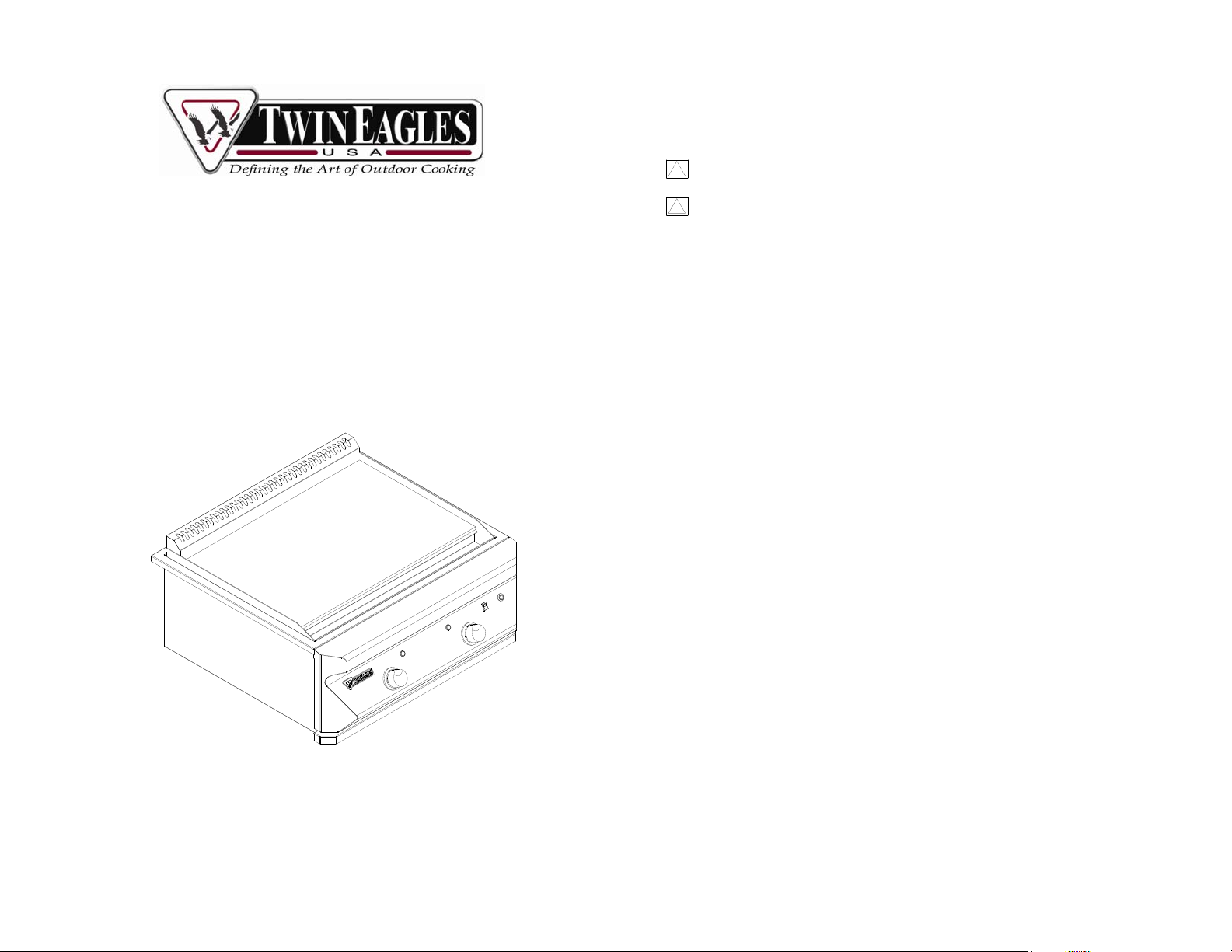
TWIN EAGLES
EPPANYAKI GRIDDLE
T
WARNING: BEFORE WORKING ON THIS APPLIANCE DISCONNECT
!
GAS AND ELECTRICAL SUPPLIES.
WARNING: INSTALLATION/GAS CONVERSION MUST BE PERFORMED
!
BY A QUALIFIED TECHNICIAN.
GAS CONVERSION KIT FROM NG TO LP
PN: CKLP-TETG
FOR MODELS: TETG
IMPORTANT: Retain original proof of purchase to establish warranty period.
Please record the following information and refer to this information when
contacting the company or an authorized service agent. This information is
found on the rating/data plate located on the inside wall of the left side Panel.
Serial No. of Teppanyaki Griddle
________________________________________________________
FOR YOUR RECORDS
Date of LP Gas Conversion:
________________________________________________________
LP Gas Conversion by:
________________________________________________________
P/N:18633A 04/11

1. Check to make sure that you have the LP Gas Conversion Kit as follows:
a. PN: 12602, Coupling, 3/8 x ½ FIP (1 pc)
b. PN 15302, LP Regulator with Hose (1 pc)
c. PN:15110-55, Orifice #55 (2 pcs)
d. PN: 18351, Label, Conversion, Gas (1 pc)
2. Griddle Plate Conversion
2-1) Remove the grease pan from the front of the Griddle Plate Assembly.
2-2) Remove the screws, located in the front of the Griddle Plate Assembly, as shown.
2-3) Raise the front of Griddle Plate Assembly and make sure the rear portion is resting
on the Griddle Top as shown in the left picture. Pull out the two Thermostat Bulbs so
that you may remove the Griddle Plate Assembly completely, as shown in the right
picture.
2-4) Unscrew the nut used to hold the U-Burner from the back and remove the UBurner.
2-5) Replace the orifices #45, used for NG, and replace it with orifice #55, used for LP.
Use a 1/2" Deep Socket and a Socket Wrench to remove and replace the orifice.
Replace Griddle Plate Assembly when finished and re-install the two Thermostat Bulbs.
2-6a) For LP Plumbed-In Connection on ly. The NG regulator is located on the bottom
side of the Teppanyaki Griddle. Remove the cap on the regulator then remove the center
plastic insert and invert it to show the LP marking. Put the cover back. Connect LP gas
line to the regulator directly.
Before (Set for NG) Setting up for LP
2-6b) For LP Tank Connection only. Remove the NG Regulator, located on the bottom
side of the unit. Use a 12” Adjustable Wrench to turn the regulator and a Pipe Wrench to
hold the manifold in place as shown below.
2-7) Install a 3/8 Flare X 1/2 FIP coupling, P/N 12602, by using a 7/8” Open Wrench to
hold the flex tubing and an adjustable wrench for the coupling. Use pipe sealant
approved for LP connection.
2-8) Install the factory supplied LP Hose and Regulator Assembly onto the coupling; do
not use sealant on the flare connection. Use an Adjustable Wrench to tighten the hose.
1

Warning: The LP Hose and Regulator Assembl y should be a Type 1 Connection
and set at 11” of Water Column.
LP Hose with regulator
3. Testing
3-1) Make sure the regulator has been properly connected, replaced for LP Gas
3-2) Check for leaks.
3-3) NEVER USE THE UNIT WITHOUT FIRST LEAK TESTING THE GAS
CONNECTION.
a) Prepare a leak testing solution of sudsy water by mixing in a spray
bottle with half liquid soap and half water.
b) Confirm that all control knobs are in the “OFF” position.
c) Turn the main gas valve supply “ON”.
d) Apply leak testing solution by spraying on the pipe joints, fittings, and
hose.
e) A gas leak is detected if;
i. there is a faint gas smell and/or
ii. growing bubbles appear on any of the connection points
and/or hose. DO NOT attempt to turn on the burners and
IMMEDIATELY turn off the gas supply valve.
f) When there is a gas leak, call a qualified service technician. DO NOT
use the unit until the leak is corrected.
3-4) Fill up the Conversion Label. Next, paste it next to the original Serial Plate.
3-5) The conversion is complete and the unit is ready for installation. Refer back to
the Installation Manual.
2
 Loading...