


Models: TEPB24HG-B
(As Shown)
TEPB24-B
TWIN EAGLES POWER BURNER
INSTALLATION, USE & CARE MANUAL
P/N: 18652B (05/14)

F O R Y O U R S A F E T Y
If you smell gas:
1. Shut off gas to the appliance.
2. Extinguish any open flames.
3. Open lid.
4. If odor continues, keep away from the
appliance and immediately call your gas
supplier or fire department.
A V E R T I S S E M E N T
S’il y a une odeur de gaz:
1. Coupez l’admission de gaz de l’appariel.
2. Éteindre toute flamme nue.
3. Ouvrir le couvercle.
4. Si l’odeur continue, évite l’appareil et
appelle tout de suite votre fournisseur de gaz
ou les pompiers.
F O R Y O U R S A F E T Y
1. Do not store or use gasoline or other
flammable vapors and liquids in the
vicinity of this or any other appliance.
2. An LP cylinder not connected for use
shall not be stored in the vicinity of this
or any other appliance.
A V E R T I S S E M E N T
1. Ne pas entreposer ni utiliser de l’essence ni
d’autres vapeurs ou liquides inflammables
dans le voisinage de l’appareil, ni de tout
autre appareil.
2. Une bouteille de propane qui n’est pas
raccordée en vue de son utilisation, ne doit
pas être entreposée dans le voisinage de cet
appareil ou de tout autre appareil.
THIS POWER BURNER IS FOR OUTDOOR
USE ONLY: If stored indoors, detach and leave
L.P. cylinder outdoors.
CE PUISSANT BRULEUR EST POUR
UTILISATION à L’ExTéRIEUR SEULEMENT:
Si l’appareil est entreposé à l’interieur, enlever
les bouteilles et les laisser à l’extérieur.
B E F O R E L I G H T I N G
1. Read instructions before lighting.
2. Remove cover during lighting.
3. If ignition does not occur in 5 seconds,
turn the burner control(s) off, wait 5
minutes, and repeat the lighting
procedure.
A V A N T D ’ A L L U M E R
L ’ A P P A R E I L
1. Lisez les instructions avant d’allumer
l’appareil.
2. Enlevez le couvercle avant d’allumer
l’appareil.
3. Si l’appareil ne s’allume pas en 5 secondes,
fermez le robinet du brûleur, attendez 5
minutes, et procédez de nouveau à l’allumage.
IMPORTANT SAFETY INFORMATION – TWIN EAGLES GAS POWER BURNER
WARNING! Read this manual carefully and completely before using your Power Burner to ensure
proper operation, proper installation, proper servicing and to reduce the risk of fire, burn hazard and/
or other injury.
a | P a g e

GENERAL SAFETY REQUIREMENTS:
In Massachusetts: All gas products must be installed using a “Massachusetts” licensed plumber or
gasfitter. A “T” handle type manual gas valve must be installed in the gas supply line to this
appliance. This applies to permanently installed natural gas and propane installations. This does not
apply to propane portable installations using a 20 pound tank.
1. The installation of this appliance must conform with local codes or, in the absence of local codes,
either the National Fuel Gas Code, ANZI Z223.1/NFPA 54, or CAN/CGA-B149.1, Natural Gas
Installation Code or CAN/CGA-B149.2, Propane Installation Code.
2. This outdoor cooking gas appliance is not intended to be installed in or on recreational vehicles
and /or boats.
3. This outdoor cooking gas appliance is intended for use outdoors and shall not be used in a
building, garage or any other enclosed area.
4. Minimum clearance of 12 inches from the back and sides of the Power Burner to adjacent
combustible construction must be maintained. This outdoor cooking gas appliance shall not
be located under overhead-unprotected combustible construction.
5. The utilization of an external electrical source requires that when installed, this outdoor cooking
gas appliance must be electrically grounded in accordance with the local codes or, in the absence
of local codes, with the National Electrical Code, ANSI/NFPA 70, or the Canadian Electrical
Code, CSA C22.1. Keep any electrical supply cord, or the fuel supply hose away from any heated
surfaces.
6. Keep your Power Burner in an area clear and free from combustible materials, gasoline and other
flammable vapors and liquids.
7. DO NOT obstruct the flow of combustion and ventilation air to this appliance. Keep the
ventilation openings of the cylinder enclosure free and clear from debris.
8. Check all gas connections for leaks with soapy water solution and brush. Never use an open
flame. (Reference page 4 for leak test procedure).
9. Check flexible hoses for cuts and wear that may affect the safety before each use.
10. Never use the Power Burner in a windy area.
11. Never use the Power Burner without the drip pan installed and push all the way to the back of the
Power Burner. Without the drip pan, hot liquid and debris could leak downward and produce a
fire hazard.
12. The pressure regulator supplied with the Twin Eagles Gas Power Burner must be used.
Replacement pressure regulators must be those specified by Twin Eagles.
13. CALIFORNIA PROPOSITION 65-WARNING: The burning of gas cooking fuel generates some
by-products which are on the list of substances known by the State of California to cause cancer
or reproductive harm. California law requires businesses to warn customers of potential exposure
to such substances. To minimize exposure to these substances always operate this unit according
to the use and care manual, ensuring you provide good ventilation when cooking with gas.
b | P a g e

TABLE OF CONTENTS – TWIN EAGLES GAS POWER BURNER
Power burner Accessories
TEPB24-BN
TEPB24-BL
TEPB24HG-BN
TEPB24HG-BL
Grate, Round, Stainless Steel
1 1
Grate, Round, Middle, Stainless Steel
1 1
Grate, Power Burner (Optional heavy duty)
1
1
Regulator, NG (NG Power burner only)
PRE-INSTALLED
Regulator, LP (LP Power burner only)
PRE-INSTALLED
GETTING STARTED…………………………………………………………………………………….. 1
GAS REQUIREMENTS
o GAS SAFETY REQUIREMENT…………………………………………..……………... 2
o LP GAS HOOKUP………….………………………………………………………..…… 3
o NATURAL GAS INSTALLATION…………………………………………………..….. 4
o LEAK TEST…………………………………………………………………………….… 4
ELECTRICAL REQUIREMENTS ……..…………………………..………………………………..… 5
ELECTRICAL WIRING DIAGRAM AND CUTOUT DIMENSIONS…………..………………….. 6
LOCATING THE POWER BURNER
o CLEARANCE TO COMBUSTIBLE CONSTRUCTION………………………..……… 7
o CLEARANCE TO NONCOMBUSTIBLE CONSTRUCTION……………….………… 7
CLEANING AND MAINTENANCE
o SPIDER AND INSECT WARNING……………………………………………………… 7
o STAINLESS STEEL……………………………………………………………………… 8
o GRATES………………………………………………………………………….…….… 8
o BURNER …………………………………………………………………….………........ 8
o DRIP PAN …………………..……………………………………………….…………… 8
OPERATING INSTRUCTIONS
o BEFORE LIGHTING THE POWER BURNER…………………………………………. 9
o TO LIGHT THE POWER BURNER BURNER ………………………………….….… 9
o MATCH LIGHTING INSTRUCTIONS ……..………...…………................................... 9
REPLACEMENT PARTS
o EXPLODED VIEW……………………………………………………….…………...….. 10
o REPLACEMENT PARTS LIST……..………………….……………….….……..……… 10
o TROUBLE SHOOTING GUIDE.....………………………………………………..…….. 11
o LIMITED PRODUCT WARRANTY…………………………………………...…..…….. 12
o WARRANTY REGISTRATION CARD
GETTING STARTED – TWIN EAGLES GAS POWER BURNER
1. Remove all packaging materials, labels and protective plastic film. DO NOT LEAVE UNIT
UNDER THE SUN WITH PROTECTIVE PLASTIC FILM ON FOR A LONG PERIOD OF
TIME AS IT WILL BE DIFFICULT TO REMOVE THE FILM.
2. Check to ensure that all Power Burner accessories listed below are included.
1 | P a g e
3. Fill up the Warranty Registration Card and
Specifications
Value
Counter Opening Height
11.50”
Counter Opening Width
22.00”
Counter Opening Depth
20.50”
Btu
70,000
NG Orifice Outer Ring
#30
NG Orifice Inner Ring
#41
LP Orifice Outer Ring
#49
LP Orifice Inner Ring
#53
mail it to the indicated address.
GAS SAFETY REQUIREMENTS – TWIN EAGLES GAS POWER BURNER
Each appliance is set and tested at the factory for the type of gas supply to be used. Identify the
type of gas, either natural gas or LP gas and make sure that the marking on the data plate (rating plate)
matches the gas being supplied to the Power Burner. The data plate is located on the panel behind the
control panel of the Power Burner. Remove the drip pan to visually access the nameplate label from
the front of the Power Burner. A second label with model number and serial number is located under
the right side of the control panel.
All gas connections should be made by a qualified technician and in accordance with local
codes and ordinances. The installation must conform with local codes or, in the absence of local
codes, with either the national Fuel Gas Code, ANSI Z223.1/NFPA 54, or CAN/CGA-B149.1, Natural
Gas Installation Code or CAN/CGA-B149.2, Propane Installation Code.
WARNING:
CHECK TO ENSURE THAT THE GAS SUPPLY HOSE DOES NOT COME IN
CONTACT WITH ANY HOT SURFACE OF THE POWER BURNER.
NEVER CONNECT THE POWER BURNER TO AN UNREGULATED GAS
SUPPLY.
GAS SAFETY REQUIREMENTS – TWIN EAGLES GAS POWER BURNER (CONTINUED)
L.P. GAS (LIQUIFIED PETROLEUM /PROPANE)
If your Power Burner is factory built for L.P., the regulator supplied is set for 10” water
column and is for use with L.P. gas only. The factory-supplied regulator must be used.
L.P. GAS SAFETY REQUIREMENT
The LP-gas supply cylinder must be constructed and marked in accordance with the
Specifications for LP-gas Cylinders of the U.S. Department of Transportation (D.O.T.) or the National
Standards of Canada CAN/CSA-B339, Cylinders, Spheres and Tubes for the Transportation of
Dangerous Goods, and Commission, as applicable; and
1. Provided with a listed overfilling prevention device.
2. Provided with a cylinder connection device compatible with the connection for outdoor cooking
appliances.
2 | P a g e
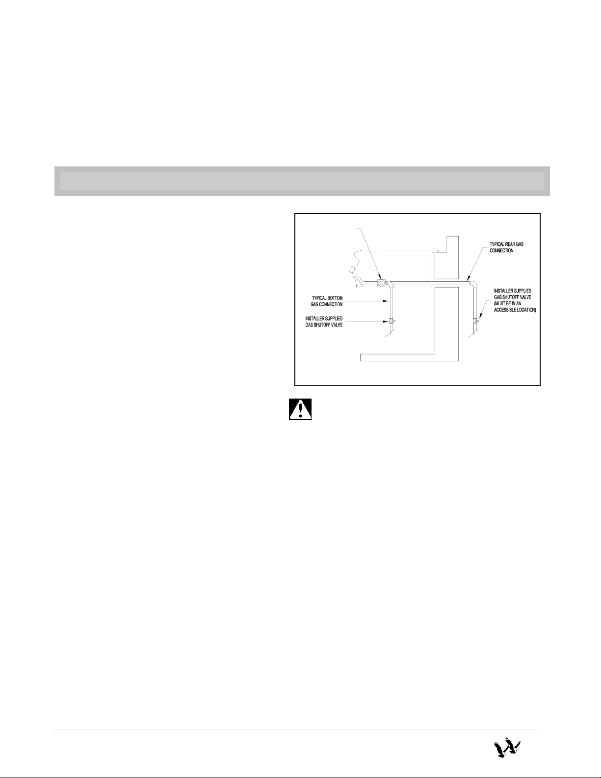
CAUTION: Provide adequate ventilation holes in the
enclosure for safety purposes in the event of a gas leak.
TYPICAL GAS HOOK UP
REGULATOR SET
AT 10” WC (LP GAS)
OR 4” WC (NG GAS)
It must be provided with a shut-off valve terminating in gas tank valve outlet. It must include a
collar to protect the cylinder valve. The cylinder supply system must be arranged for vapor
withdrawal.
Do not operate the gas Power Burner indoors or in any enclosed area. If the gas Power Burner is
not in use, the gas must be turned off at the supply cylinder. If the Power Burner is to be stored
indoors, disconnect the gas supply cylinder and leave the cylinder outdoors.
LP GAS HOOK-UP – TWIN EAGLES GAS POWER BURNER
A typical LP gas installation is shown
on the right. Make sure that the factorysupplied regulator is used and installed with the
arrow mark on the regulator pointing towards
the Power Burner. Do not use any replacement
regulator other than that specified by Twin
Eagles. Use only pipe sealants that are
approved for use with natural and LP gases. An
installer-supplied gas shutoff valve must be
installed in an accessible location. (Reference:
page 4 for leak test procedure). Although LP
gas cylinder may be used, it is not
recommended due to the large amount of
gas consumption of the unit and will freeze
up the LP gas cylinder.
Note: An enclosure for LP gas cylinder must be vented on the level of the cylinder valve and at floor
level. The effectiveness of the opening(s) for purposes of ventilation shall be determined with the LP
gas supply cylinder in place. This shall be accomplished by one of the following:
a. One side of the enclosure shall be fully open; or
b. For an enclosure having four sides, a top and a bottom:
1. At least two ventilation openings at cylinder valve level shall be provided in the sidewall,
equally sized, spaced at 180 degrees (3.14 rad), and unobstructed. Each opening shall have
a total free area of not less than 1/2 square inch per pound (7.1 cm2/kg) of stored fuel
capacity and not less than a total free area of 10 square inches (64.5 cm2).
Ventilation opening(s) shall be provided at floor level and shall have a total free area of not
less than ½" square inch per pound (7.1 cm2/kg) of stored fuel capacity and not less than a total free
area of 10 square inches (64.5 cm2). If ventilation openings at floor level are in a sidewall, there shall
be at least two openings. The bottom of the openings shall be at floor level and the upper edge no more
than 5 inches (127 mm) above the floor. The openings shall be equally sized, spaced at 180 degrees
(3.14 rad) and unobstructed.
3 | P a g e

NATURAL GAS INSTALLATION – TWIN EAGLES GAS POWER BURNER
The installation must conform with local codes or, in the absence of local codes, with either
the national Fuel Gas Code, ANSI Z223.1/NFPA 54, or CAN/CGA-B149.1, Natural Gas
Installation Code or CAN/CGA-B149.2, Propane Installation Code.
1. This gas appliance and its individual shutoff valve must be disconnected from the gas supply
2. This appliance must be isolated from the gas supply piping system by closing its individual
water column. The regulator is convertible to 10” water column for system LP application. Do not
use with a 20-lb LP cylinder. Make sure that the regulator is set for natural gas. To check, remove
the brass hex cap. You will find the conversion plastic pin attached to the cap to the underside of
the cap. If the disc (1/2 in. diameter) of the pin is close to the cap, then the regulator is set for
natural gas. If the disc is at the tip of the pin, away from the brass cap, the regulator is set for
system LP application. To convert to natural gas, remove the plastic conversion pin and invert and
replace it back in a manner such that the disc is close to the brass cap. For both natural and LP, the
maximum inlet pressure is 14” water column.
regulator is used and installed with the arrow mark on the regulator pointing towards the gas
Power Burner. Do not use any replacement regulator other than that specified by Twin Eagles. Use
only pipe sealants that are approved for use with natural and LP gases. An installer-supplied gas
shutoff valve must be installed in an accessible location.
piping system during any pressure testing of that system at the test pressures in excess of 1/2
psi (3.5 kPa).
manual shutoff valve during any pressure testing of the gas supply piping system at test
pressures equal to or less than 1/2 psi (3.5 kPa).
If the gas Power Burner is factory built for natural gas, the regulator supplied is set for 4”
A typical natural gas installation is shown on page 3. Make sure that the factory-supplied
LEAK TEST – TWIN EAGLES GAS POWER BURNER
CAUTION BEFORE TESTING
Finding and/or fixing a gas leak is NOT a “DO-IT-YOURSELF” procedure.
NEVER USE THE POWER BURNER WITHOUT FIRST LEAK TESTING THE GAS
CONNECTIONS.
WARNING: DO NOT USE OPEN FLAME TO CHECK FOR LEAKS. USE OF AN OPEN
FLAME COULD RESULT IN A FIRE, EXPLOSION AND BODILY HARM.
DO NOT SMOKE WHILE PERFORMING THE LEAK TEST!
To prevent fire or explosion hazard, DO NOT use or permit sources of ignition in the area
while performing a leak test. Perform leak test outdoors only.
Check to ensure that flexible hoses do not have any cuts and wear that may affect the safety
before each use. Only the factory supplied regulator must be used. Use only replacement
regulator specified by Twin Eagles.
4 | P a g e

LEAK TEST
AVERTISSEMENT
Instruction pour la mise à la terre electrique:
Cet appareil est muni d’une fiche à trois
broches (mise à la terre) afin de vous protéger
des chocs et doit être branché directement dans
une prise de courant à trois broches
adéquatement mise à la terre. Il ne faut pas
couper ou enlever la broche de mise à la terre
de cette fiche.
WARNING
Electrical Grounding Instructions:
This outdoor gas cooking appliance is equipped
with a three prong (grounding) plug for your
protection against shock hazard and should be
plugged directly into a properly grounded three
prong outlet. Do not cut or remove the third
prong from this plug.
The Power Burner requires 120 volt supply. The power supply cord on the
Power Burner is equipped with a 3-prong (grounded) plug for protection against
shock hazard. Do not cut or remove the grounding prong from the plug.
1) Prepare a leak testing solution of sudsy
water by mixing in a spray bottle with
half liquid soap and half water.
2) Confirm that all control knobs are in the
OFF position.
3) Turn the main gas valve supply ON.
4) Apply leak testing solution by spraying
on the pipe joints, fittings, and hose.
5) A gas leak is detected if;
a) there is a faint gas smell and/or…
b) …growing bubbles appear on any of
the connection points and/or hose,
DO NOT attempt to ignite the Power
Burner and IMMEDIATELY turn off
the gas supply valve.
6) When there is a gas leak, call a qualified
service technician. DO NOT use the
Power Burner until the leak is corrected.
ELECTRICAL REQUIREMENTS – TWIN EAGLES GAS POWER BURNER
The Twin Eagles Power Burner has a power transformer which is concealed in a stainless steel box with
an attached power supply cord. This transformer must be secured in a dry location.
1. In an island application locate the Power Burner near the GFCI 120V outlet in a dry location.
2. Plug-in the transformer’s power cord to the properly grounded GFCI 120V outlet.
5 | P a g e

CONNECTION
DIAGRAM
LADDER
Note:
It is recommended to build
the enclosure for the power
burner 6”-12” lower than
the countertop.
ELECTRICAL WIRING DIAGRAM AND TYPICAL CUTOUT DIMENSION
Burner under overhead combustible surfaces. Do not operate the Power Burner inside a building,
garage, recreation vehicle or any enclosed area. When choosing an area, consider exposure to wind,
proximity to traffic paths and length of gas supply line. Keep gas supply lines as short as possible to
reduce pressure drop. Keep the Power Burner away from windy area but keep the Power Burner in a
well-ventilated area. Do not obstruct the flow of combustion and ventilation air around the Power
Burner. The supporting edges of the Power Burner must be located level and flat. The counter should
also be leveled.
6 | P a g e
LOCATING THE POWER BURNER – TWIN EAGLES GAS POWER BURNER
This gas appliance is designed and certified for outdoor use only. Do not locate this Power

SPIDER AND INSECT WARNING
Spiders and other insects can nest in the burner of this and any other Power Burner, which causes the gas
to flow from the front of the burner. This dangerous “condition” can cause a fire behind the valve panel, damaging
the Power Burner and making the Power Burner unsafe to operate. Inspect the burners once a year or if the Power
Burner has not been used for more than one month or if any of the following conditions occur:
1) The smell of gas in conjunction with the burner flames appearing yellow.
2) The Power Burner does not reach temperature.
3) The Power Burner heats unevenly.
4) The burner makes popping noises.
CLEARANCE TO COMBUSTIBLE CONSTRUCTION
A minimum clearance of 12” from the sides and 6” from the back of the Power Burner to adjacent
vertical combustible construction must be maintained.
DÉGAGEMENT DE TOUTE CONSTRUCTION COMBUSTIBLE
Il faut maintenir une distance minimum de 12 po (30.48 cm) sur les côtés et de 6 po (15.24 cm) sur
l’arrière du gril par rapport aux constructions combustibles verticales adjacentes.
CLEARANCE TO NONCOMBUSTIBLE CONSTRUCTION
A minimum clearance of 1” from the back of the Power Burner above cooking surface to non-
combustible construction is required.
A minimum of 1” clearance to the sides of the Power Burner above cooking surface to non-
combustible construction is recommended. The Power Burner can be installed directly next to noncombustible construction below the cooking surface.
DÉGAGEMENT DE TOUTE CONSTRUCTION INCOMBUSTIBLE
Une distance minimum de 1 po (2.54 cm) de l’arrière du Puissant Bruleur au-dessus de toute surface de
cuisson à la construction incombustible est prescrite.
Une distance minimum de 1 po (2.54 cm) des côtés du Puissant Bruleur au-dessus de la surface de
cuisson à la construction incombustible est recommandée. Le Puissant Bruleur peut être installé
directement à proximité d’une construction incombustible en-dessous de la surface de cuisson.
CLEANING & MAINTENANCE – TWIN EAGLES GAS POWER BURNER
7 | P a g e

CLEANING & MAINTENANCE – TWIN EAGLES GAS POWER BURNER
DRIP PAN
The drip pan collects grease, liquid and fallen food particles.
Allow the pan and its contents to cool before cleaning. Slide the pan out
and wipe it clean. Make sure the drip pan is fully inserted back into the
Power Burner. It is highly recommended to clean the pan after every use
to avoid any possibility of a grease fire. DO NOT use the Power Burner
without the drip pan pushed all the way to the back of the Power Burner
unit.
POWER BURNER GRATE
(a) Round Grates
The easiest way to clean the grates is to scrub them with a
barbeque brush immediately after cooking is completed and the flame is
turned off.
Wear a barbeque mitt to protect your hands from the heat and
steam. Dip a brass bristle barbeque brush in tap water and scrub the hot
grates. Dip the brush frequently in tap water. Steam, created as water
comes in contact with the hot Power Burner, helps loosen food particles
stuck in the Power Burner. These food particles will either get burned or
fall into the cleaning pan. Cleaning of the Power Burner would be
longer and more difficult if the Power Burner grates are allowed to cool
before cleaning.
(b) Heavy Duty Grate
Use warm water and soap to clean the heavy duty grates. Use
non-abrasive sponge to clean off the food particles.
BURNERS
Burners are made of heavy gauge brass and can be cleaned using
a bristle brush, warm water and soap. Check every port hole for clogs.
Use a wire pin to clean out clogged ports. Make sure the burner is dry
before installing it back to the Power Burner.
a
b
STAINLESS STEEL
The TWIN EAGLES Power Burner is made of stainless steel construction. It is non-rusting and nonmagnetic. Never clean the stainless steel when it is hot. After the initial cooking use, certain areas of the Power
Burner may discolor. This is a normal discoloration caused by the intense heat given off by the burner. Specks of
grease can gather on the surface of the stainless steel and get baked-on. These can be removed by using a mild
abrasive pad (like Scotch Brite) with a stainless steel cleaner. Use the mildest cleaner and always scrub in the
direction of the grain.
Do not use steel wool to clean the Power Burner. Do not use abrasives on the polished highlights. Be
extra careful when cleaning around the highlights. Metal polisher or mild chrome cleaner can be used to bring
back the luster on highlights. To touch-up minor scratches in the stainless steel, sand the affected surface very
lightly, with 100-dry grit emery sandpaper in the direction of the grain.
8 | P a g e

OPERATING INSTRUCTIONS – TWIN EAGLES GAS POWER BURNER
Match/BBQ Lighter Lighting Instructions:
If there is no electrical power supply available or if hot surface igniter will not light the burners, the
burners can be lit manually using a lighted long match, taper or BBQ lighter.
1. Push and turn the knob counter-clock-wise to the biggest flame marking on the bezel. Hold the
knob pushed in for 5 seconds.
2. Insert a lit match or BBQ lighter thru the grates and near the top of the burner. Once you see
or hear a flame you can release the knob.
TO LIGHT THE POWER BURNER’S BURNER
Lighting the Power Burner
1. Open the gas supply shut-off valve.
2. Push in the knob and verify that the hot surface igniter glows. If the igniter does not
glow, verify for proper power supply. (Reference page 5 for electrical
requirements).
3. Once the glowing is verified for 5 seconds simultaneously push-in and turn the
knob counter-clock-wise to the biggest flame marking on the bezel. Hold the
knob pushed in for 5 seconds. Once you see or hear a flame you can release the
knob.
CAUTION: If ignition does not take place within 5 seconds, turn knob to the OFF
position, wait for five minutes and repeat step 3.
Important: If burner fails to light within 5 seconds, turn off gas and
wait 5 minutes before repeating the process.
Warning: If you smell gas, shutoff the gas supply and immediately
check for leaks using the soapy water technique.
BEFORE LIGHTING THE POWER BURNER
DO NOT ATTEMPT TO LIGHT THE POWER BURNER IF YOU SMELL GAS.
WARNING! IT IS CRITICAL THAT THE GAS BURNERS ARE PROPERLY INSTALLED WITH
THEIR ORIFICES INSIDE THE BURNERS AIR SHUTTERS. If not properly installed, gas may leak
outside of the burner that could lead to fire, potential damage to your Power Burner and bodily injury.
Inspect the gas supply piping or hose prior to turning the gas ON. If there is evidence of cuts, wear, or
abrasion, it must be replaced prior to use. The replacement pressure regulator and hose assembly must be the
type specified by the manufacturer. Do not use the Power Burner if the odor of gas is present. The pressure
regulator and hose assembly supplied with the units must be used.
If the unit is LP, screw the regulator and hand tighten to the valve of the cylinder and leak check the hose and
regulator connections with a soap and water solution before operating the Power Burner. Reference page 4
for leak test procedure.
Always keep your face and body as far away as possible when lighting.
Refer to spiders and insects warning and procedure under the cleaning and maintenance page of this manual.
9 | P a g e

REPLACEMENT PARTS – TWIN EAGLES GAS POWER BURNER
Item
No.
TE Part
Number
Description
TEPB24HG
-BL
TEPB 24HG
-BN
TEPB 24
-BL
TEPB 24
-BN
Item
No.
TE Part
Number
Description
TEPB24HG
-BL
TEPB 24HG
-BN
TEPB 24
-BL
TEPB 24
-BN
1
S22321
Power Burner Cover
1 1 1 1 15
S13147
Twin Eagles Emblem
1 1 1
1
2
S22330Y
Power Burner HD Grate
1
1
16
S13128
Bezel Knob
2 2 2 2 3
S16230
Hot Surface Igniter
1 1 1 1 17
S13154
Knob 2 2 2 2
4
S22309
Top Trim
1 1 1 1 18
S16192
LED Holder
2 2 2
2
5
S13362Y
Brass Burner
1 1 1 1 19
S22310Y
Front Panel
1 1 1 1 6
S22328
Transformer Cover
1 1 1 1 20
S12407
Flex Tubing, 7 “
2 2 2
2
7
S16111
Power Cord
1 1 1 1 21
S12603
Brass Elbow Burner
2 2 2
2
8
S16302
Transformer, 12V 3A
1 1 1 1 22
S15101Y
Gas Valve with Microswitch
2 2 2
2
9
S15303
Regulator, NG
1
1
23
S12601
Brass Elbow 3/8 CC x 1/8 FIP
2 2 2
2
10
S15303
REGULATOR, NG
(CONVERTED TO LP)
1 1 24
S13891
Power Burner Round Grates
1
1
11
S12750
Manifold
1 1 1 1 25
S13892
Power Burner Middle Round Grate
1
1
12
S14420
Roller Bearing
4 4 4 4 26
S13117
Handle Cover
1 1 1
1
13
S22315Y
Drip Pan Assembly
1 1 1 1 27
S22341Y
Flame Diverter Assembly
1 1 14
S16196
Illuminated light switch
1 1 1
1 S16297Y
Wire Harness (Not Shown)
1 1 1
1
Tools Required:
1.) Philips Screwdriver
2.) Adjustable Wrench
3.) Set of Socket Wrenches
4.) Pipe Sealant
10 | P a g e

TROUBLESHOOTING GUIDE – TWIN EAGLES GAS POWER BURNER
PROBLEM
WHAT TO DO
Power Burner will not
light.
1. Push in the knob and verify that the igniter glow.
2. If the igniter does not glow, verify proper power supply. GFCI 120V.
a. Purge the line of any trapped air.
b. Check if you can match-light the burner.
NOTE: It is normal to hear a popping sound when the Power Burner
burners are first turned ON.
Burner flame is yellow
and gas odor can be
smelled.
1. Check the burner inlet for obstruction…ex. Spiders, insects, etc.
2. Check the air shutter for proper adjustment.
3. Check any source of gas leak.
Low heat generated with
knob in HI position.
1. Check if the problem is isolated to only one burner. If it appears so, clean
the orifice and burner, clearing ports of any obstruction.
2. Check for any bent or kinked fuel hose.
3. Check if the air shutter is properly adjusted.
4. Check for proper gas supply and pressure.
5. Pre-heat Power Burner for 15 minutes.
6. If using LP gas, check for empty tank.
Too much heat.
1. Check for damaged orifice or no orifice.
2. Check for unauthorized regulator adjustment.
Burner blows out
1. Check for any burner defect.
2. Check for proper burner installation.
3. Check if fuel mixture is too lean.
4. Check if gas supply is sufficient.
5. Check if LP tank is empty.
6. Check if the Power Burner location is subject to high winds.
Glow igniter
will not turn ON.
1. Check if the unit is plugged into proper voltage (GFCI 120V).
Front panel lights
will not turn ON.
1. Check if the unit is plugged into proper voltage (GFCI 120V).
BEFORE CALLING FOR SERVICE:
If your Twin Eagles Power Burner does not function properly, use the following troubleshooting
guide before contacting your dealer for service. The troubleshooting guide may save the cost of a
service call and the inconvenience of being without your Power Burner.
11 | P a g e

TWIN EAGLES POWER BURNER WARRANTY
LIMITED LIFETIME WARRANTY: Twin Eagles warrants the main burners, grates and all fabricated stainless steel
components, to be free from defects in materials and workmanship under normal
residential use for the lifetime of the product. This warranty excludes discoloration,
surface scratches, weather and atmospheric related staining, and minor surface rust and
oxidation which are normal conditions and to be expected with any outdoor product.
The actual part will be repaired or replaced, free of charge, with the owner paying for
all other costs, including labor and freight.
FIVE YEAR LIMITED WARRANTY: Twin Eagles warrants the gas valves, and drip pans to be free from defects in
materials and workmanship under normal residential use for a period of five years from
the original date of purchase. The actual part will be repaired or replaced, free of
charge, with the owner paying for all other costs including labor and freight.
ONE-YEAR FULL WARRANTY: Twin Eagles warrants the outdoor gas Power Burner and all of their component parts, to
be free from defects in materials and workmanship under normal residential use for a
period of one year from the original date of purchase. Twin Eagles will repair or
replace, at its option, any part, which fail or is found to be defective during the
warranty period, at no cost to the original purchaser. Warranty service must be
performed by a Twin Eagles authorized representative during normal business hours.
NINETY (90) DAY RESIDENTIAL PLUS WARRANTY: This warranty applies to applications where use of the product
extends beyond normal residential use such as bed and breakfast inn and private clubs.
The actual part will be repaired or replaced, free of charge, with the owner paying for
all other costs including labor and freight. This warranty excludes all commercial
locations such as restaurants and food service locations.
WARRANTY LIMITATIONS & EXCLUSIONS
This warranty shall apply only to the products purchased and located in the continental United States and Canada. The
warranty coverage begins on the original date of purchase and proof of date of purchase is required. In order to activate the
warranty, we require that you send in the attached warranty registration card. This warranty applies only to the original owner
and may not be transferred.
This warranty does not apply to damages resulting from negligence, alteration, misuse, abuse, accident, natural disaster, loss
of electrical power to the product for any reason, improper installation or improper operation, unauthorized adjustments or
calibrations, dings, dents, scratches, or damages due to harsh cleaning chemicals. This warranty does not apply to commercial
use, or to products with altered or removed serial numbers. Twin Eagles shall not be liable for incidental, consequential,
special or contingent damages resulting from its breach of this written warranty or any implied warranty.
WARRANTY SERVICE & REPLACEMENT PARTS: Call your authorized selling dealer or call Twin Eagles directly at
800-789-2206. Be prepared to furnish the following information: Purchaser’s name, model and serial number of the Power
Burner, date of purchase and the accurate description of the problem. Twin Eagles will not pay for service calls for correcting
an installation problem. Owner shall be responsible for proper installation, providing normal care and maintenance, providing
proof of purchase upon request and making the Power Burner accessible for service. In the event of any warranty
replacement, all removal, replacement, installation and shipping costs are the responsibility of the Power Burner owner.
Some states do not allow limitations on how long an implied warranty lasts, or the exclusions of or limitations on
consequential damages. This warranty gives you specific legal rights and you may have other rights, which vary from state to
state.
12 | P a g e

Customer Name
Model #
Address
Serial #
City
Date Purchased
Zip
Dealer’s Name
Phone #
Dealer’s Address
e-mail:
Cut
Here
Or you may register online at http://www.twineaglesbbq.com/contactus.shtml
HOW TO OBTAIN SERVICE
For service, please contact your TWIN EAGLES dealer or call TWIN EAGLES direct at (800) 7892206 or (562) 802-3488 or fax (562) 802-3391
Mailing address:
Twin Eagles, Inc.
13231 East 166th Street
Cerritos, CA 90703
Visit us at www.twineaglesbbq.com
Please provide:
Model number
Serial Number
Date of installation
A description of the problem
This Warranty Registration card must be returned within thirty days of purchased to properly activate
your warranty. This information is for our internal use only.
Warranty Registration

FOR YOUR RECORDS
Place
Postage
Here
Cut
Here
Please record the following information and refer to them when contacting the
company or an authorized service agent. This information is found on the data
nameplate, located on the panel behind the control panel of the Power Burner.
Remove the drip pan to visually access the nameplate from the front of the Power
Burner. A second label with model number and serial number is located under the
right side of the control panel.
Model #: ________________________________
Serial #: _________________________________
Date of Purchase: __________________________
Place of Purchase: __________________________
Type of Gas: NG LP
Customer Service
ATTN: Warranty Department
13231 East 166th Street
Cerritos, CA 90703
Fax no. (562) 802-3391
 Loading...