

Page 1
Twin Eagles
Outdoor Refrigerator
18910 04/15
Model: TEOR24-E
Page 2
CONTENTS
Contents:
Safety information ...............................................................2
Unpacking your appliance ..................................................3
Warranty registration .....................................................3
Installing your appliance ......................................................4
Cabinet clearances .........................................................4
Leveling the appliance ....................................................4
Electrical connection ......................................................5
Installing the anti-tip device .................................................6
Product Dimensions ...........................................................8
Using your Electronic control ............................................10
Starting your appliance ..................................................10
Turning your appliance "ON" or "OFF" ..........................10
Adjusting the temperature .............................................10
Refrigerator operation ...................................................10
Alarms ............................................................................10
Door ajar ...................................................................10
Temperature sensor fault ..........................................10
Shelving congurations .....................................................11
Care and cleaning .............................................................13
Long term storage / winterization ................................ 14
Stainless steel maintenance ............................................15
Energy saving tips ............................................................15
Door alignment .................................................................16
Troubleshooting ................................................................17
Obtaining service ..............................................................17
Warranty ...........................................................................18
Important Safety Instructions
Warnings and safety instructions appearing in this guide
are not meant to cover all possible conditions and situations that may occur. Common sense, caution, and care
must be exercised when installing, maintaining, or operating this appliance.
Recognize Safety Symbols,
Words, and Labels.
!
WARNING
WARNING-You can be killed or seriously injured if
you do not follow these instructions.
!
CAUTION
CAUTION-Hazards or unsafe practices which could re-
sult in personal injury or property / product damage.
NOTE
NOTE-Important information to help assure a problem
free installation and operation.
State of California Proposition 65 Warnings:
WARNING: This product contains one or more chemicals
known to the State of California to cause cancer.
WARNING: This product contains one or more chemicals
known to the State of California to cause birth defects or
other reproductive harm..
2
Page 3
UNPACKING YOUR APPLIANCE
!
WARNING
EXCESSIVE WEIGHT HAZARD
Use two or more people to move product.
Failure to do so can result in personal injury.
Remove Interior Packaging
Your appliance has been packed for shipment with all parts
that could be damaged by movement securely fastened.
Remove internal packing materials and any tape holding internal components in place. The owners manual is shipped
inside the product in a plastic bag along with the warranty
registration card, and other accessory items.
Important
Keep your carton and packaging until your appliance has
been thoroughly inspected and found to be in good condition. If there is damage, the packaging will be needed as
proof of damage in transit. Afterwards please dispose of all
items responsibly.
Warranty Registration
It is important you send in your warranty registration card
immediately after taking delivery of your appliance or you
can register online at:
http://www.twineaglesbbq.com/contactus.shtml
The following information will be required when registering
your appliance.
Service Number
Serial Number
Date of Purchase
Dealer’s name and address
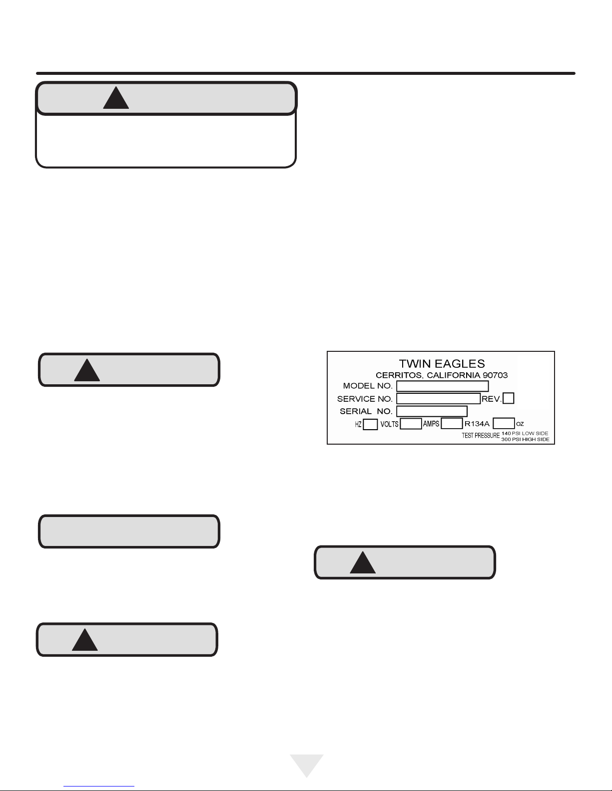
The service number and serial number can be found on the
serial plate which is located inside the cabinet on the left
side near the top. (See gure 1).
!
CAUTION
Dispose of the plastic bags which can be a suffocation
hazard.
Note to Customer
This merchandise was carefully packed and thoroughly
inspected before leaving our plant. Responsibility for its
safe delivery was assumed by the retailer upon acceptance
of the shipment. Claims for loss or damage sustained in
transit must be made to the retailer.
NOTE
DO NOT RETURN DAMAGED MERCHANDISE TO THE
MANUFACTURER - FILE THE CLAIM WITH THE
RETAILER.
!
CAUTION
If the appliance was shipped, handled, or stored in other
than an upright position for any period of time, allow the appliance to sit upright for a period of at least 24 hours before
plugging in. This will assure oil returns to the compressor.
Plugging the appliance in immediately may cause damage
to internal parts.
Figure 1
!
CAUTION
Help Prevent Tragedies
Child entrapment and suffocation are not problems of the
past. Junked or abandoned refrigerators are still dangerous
- even if they sit out for "just a few hours".
If you are getting rid of your old refrigerator, please follow
the instructions below to help prevent accidents.
Before you throw away your old refrigerator or freezer:
• Take off the doors or remove the drawers.
• Leave the shelves in place so children may not easily
climb inside.
3
Page 4
INSTALLING YOUR APPLIANCE
Select Location
The proper location will ensure peak performance of your
appliance. We recommend a location where the unit will
be out of direct sunlight and away from heat sources. To
ensure your product performs to specications, the recommended installation location temperature range is from 55
to 115°F (13 to 46°C).
Cabinet Clearance
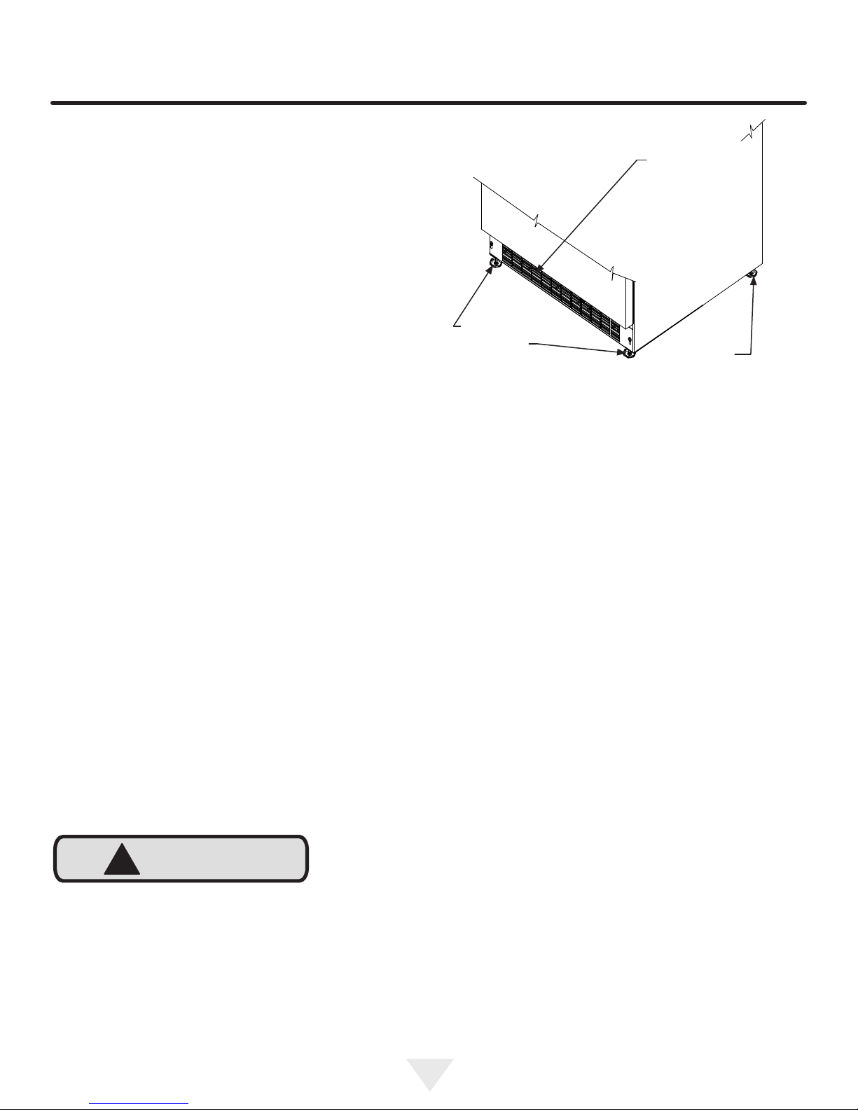
Ventilation is required from the bottom front of the appliance. Keep this area open and clear of any obstructions.
Adjacent cabinets and counter top can be installed around
the appliance as long as the front grille remains unobstructed.
Front Grille,
keep this area
open.
Front Leveling
Legs
Figure 2
Rear
Leveling
Legs
Leveling Legs
Adjustable legs at the front and rear corners of the appli-
ance should be set so the unit is rmly positioned on the
oor and level from side to side and front to back. The
overall height of your appliance may be adjusted between
the minimum, 333⁄4" (85.7 cm), by turning the leveling leg in
(CW ↷) and the maximum, 343⁄4" (88.3 cm) by turning the
leveling leg out (CCW ↶).
!
CAUTION
Front Grille
Do not obstruct the front grille. The openings within the
front grille allow air to ow through the condenser heat exchanger. Restrictions to this air ow will result in increased
energy usage and loss of cooling capacity. For this reason
it is important this area not be obstructed and the grille
openings kept clean. Twin Eagles does not recommend the
use of a custom made grille as air ow may be restricted.
(See Figure 2).
To adjust the leveling legs, place the appliance on a solid
surface and protect the oor beneath the legs to avoid
scratching the oor. With the assistance of another person,
lean the appliance back to access the front leveling legs.
Raise or lower the legs to the required dimension by turning
the legs. Repeat this process for the rear by tilting the appliance forward using caution. On a level surface check the
appliance for levelness and adjust accordingly.
The front grille screws may be loosened and the grille adjusted to the desired height. When adjustment is complete
tighten the two front grille screws. (See Figure 5).
4
Page 5
INSTALLING YOUR APPLIANCE
!
WARNING
Figure 3
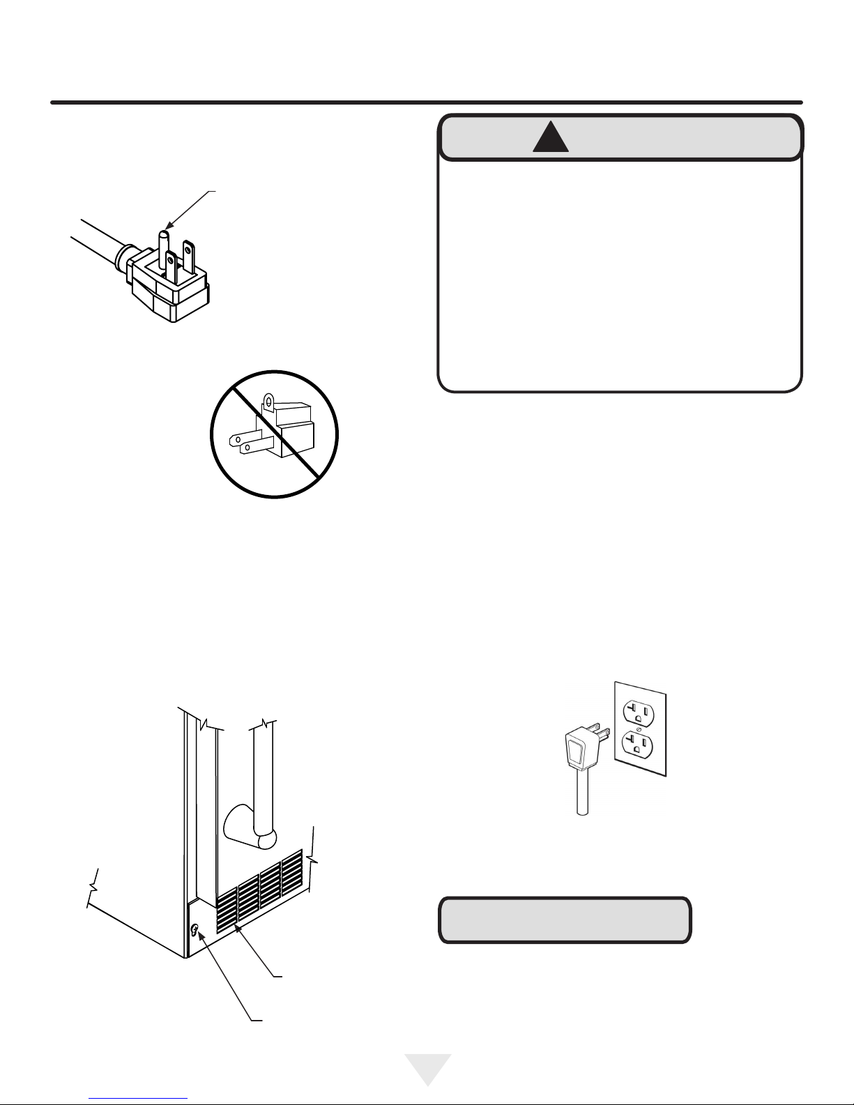
Do not remove
ground prong
Figure 4
Electrical Shock Hazard
• Do not use an extension cord with this appliance.
They can be hazardous and can degrade product
performance.
• This appliance should not, under any circumstances, be installed to an un-grounded electrical supply.
• Do not remove the grounding prong from the power
cord. (See Figure 3).
• Do not use an adapter. (See Figure 4).
• Do not splash or spray water from a hose on the
appliance. Doing so may cause an electrical shock,
which may result in severe injury or death.
Electrical Connection
A grounded 115 volt, 15 amp dedicated circuit is required.
This product is factory equipped with a power supply
cord that has a three-pronged, grounded plug. It must be
plugged into a mating grounding type receptacle in accordance with the National Electrical Code and applicable lo-
cal codes and ordinances (see Figure 6). If the circuit does
not have a grounding type receptacle, it is the responsibility
and obligation of the customer to provide the proper power
supply. The third ground prong should not, under any circumstances, be cut or removed.
Figure 5
Front grille
Front grille screw
Figure 6
NOTE
Ground Fault Circuit Interrupters (GFCI) are prone to nuisance tripping which will cause the appliance to shut down.
GFCI’s are generally not used on circuits with power equipment that must run unattended for long periods of time, unless required to meet local building codes and ordinances.
5
Page 6
INSTALLING THE ANTI TIP DEVICE
FOR FREESTANDING INSTALLATIONS
!
WARNING
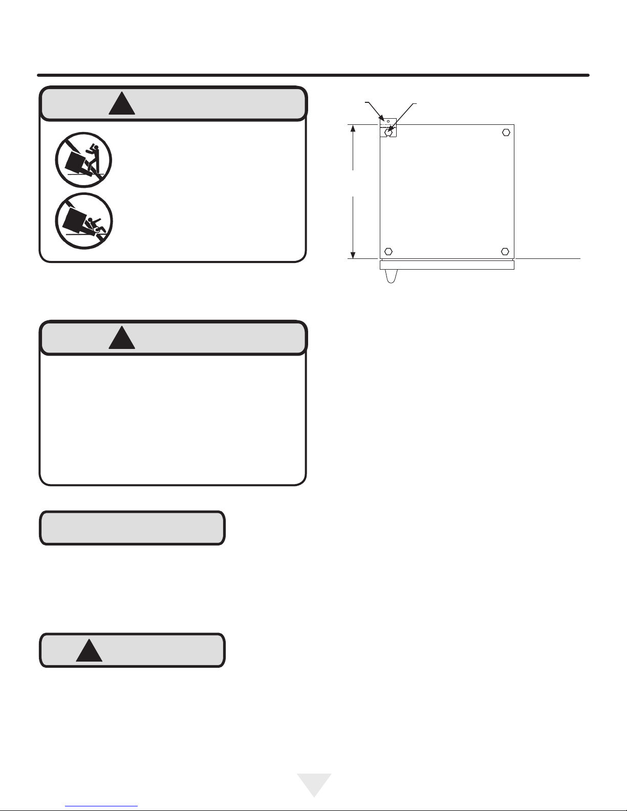
• ALL APPLIANCES CAN TIP
RESULTING IN INJURY.
Anti-Tip
Bracket
Leveling Leg
• INSTALL THE ANTI-TIP
BRACKET PACKED WITH
THE APPLIANCE.
• FOLLOW THE INSTRUCTIONS BELOW
Anti-Tip Device
!
WARNING
If your refrigerator is not located under a counter
top (free standing), you must use an anti-tip device
installed as per these instructions. If the refrigerator is
removed from its location for any reason, make sure
that the device is properly engaged with the anti-tip
bracket when you push the refrigerator back into the
original location. If the device is not properly engaged,
there is a risk of the refrigerator tipping over, with the
potential for property damage or personal injury.
NOTE
If installing on a concrete oor, concrete fasteners are
required, (not included with the anti-tip kit).
211⁄2"
(54.6 cm)
Bottom View of
Refrigerator
Front of cabinet
Figure 7
Step by step instructions for locating the
position of the bracket:
1) Decide where you want to place the refrigerator. Slide it
into place, being careful not to damage the oor, leaving 1"
(2.5 cm) of clearance from the rear wall to allow room for
the anti-tip bracket.
2) Raise the rear leveling legs approximately 1⁄4" (6 mm) to
allow engagement with the anti-tip bracket. Level the unit
by adjusting all the leveling legs as required. Turning the
leveling leg counterclockwise will raise the unit and clockwise will lower the unit.
3) Make sure the refrigerator is in the desired location, then
mark on the oor the rear and side corner of the cabinet
where the anti-tip bracket will be installed. If the installation
does not allow marking the rear corner of the cabinet, then
make temporary lines on the oor marking the front corner
of the cabinet, excluding the door. Slide the refrigerator out
of the way. From the temporary line extend the sidewall line
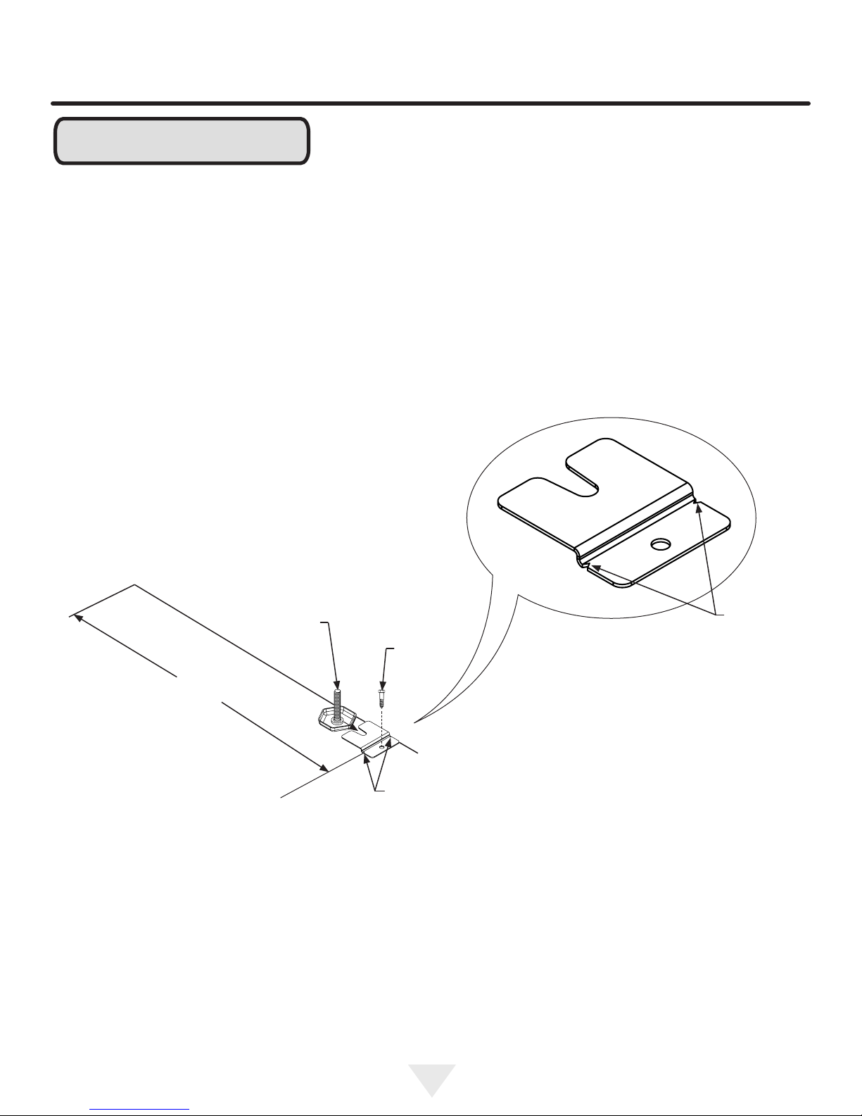
back 211⁄2" (54.6 cm) as shown in Figure 8.
!
CAUTION
Any nished ooring should be protected with appropriate
material to avoid damage when moving the unit.
Floor Mount Installation
The anti-tip bracket is to be located on the oor in the left or
right rear corner of the refrigerator as shown in Figure 7.
4) Align the anti-tip bracket to the marks on the oor so
the side of the bracket lines up with the side of the cabinet
mark, and the "V" notches on the anti-tip bracket line up
with the end of the 211⁄2" (54.6 cm) line (Rear of cabinet
line).
5) Fasten the anti-tip bracket to the oor using the supplied
screw. (See Figure 8).
6) Slide the cabinet back into position, making sure the rear
cabinet leveling leg slides under the anti-tip bracket engaging the slot.
6
Page 7
INSTALLING THE ANTI TIP DEVICE
FOR FREESTANDING INSTALLATIONS
NOTE
When the oor mounted anti-tip bracket is used the minimum adjusted height of the cabinet is increased by
3
⁄8" (9 mm).
Front of cabinet line
Side of cabinet line
211⁄2"
(54.6 cm)
Figure 8
Rear Leveling leg
Rear of cabinet line
Screw
"V" notches
in bracket
Figure 8a
"V" notches
in bracket
7
Page 8
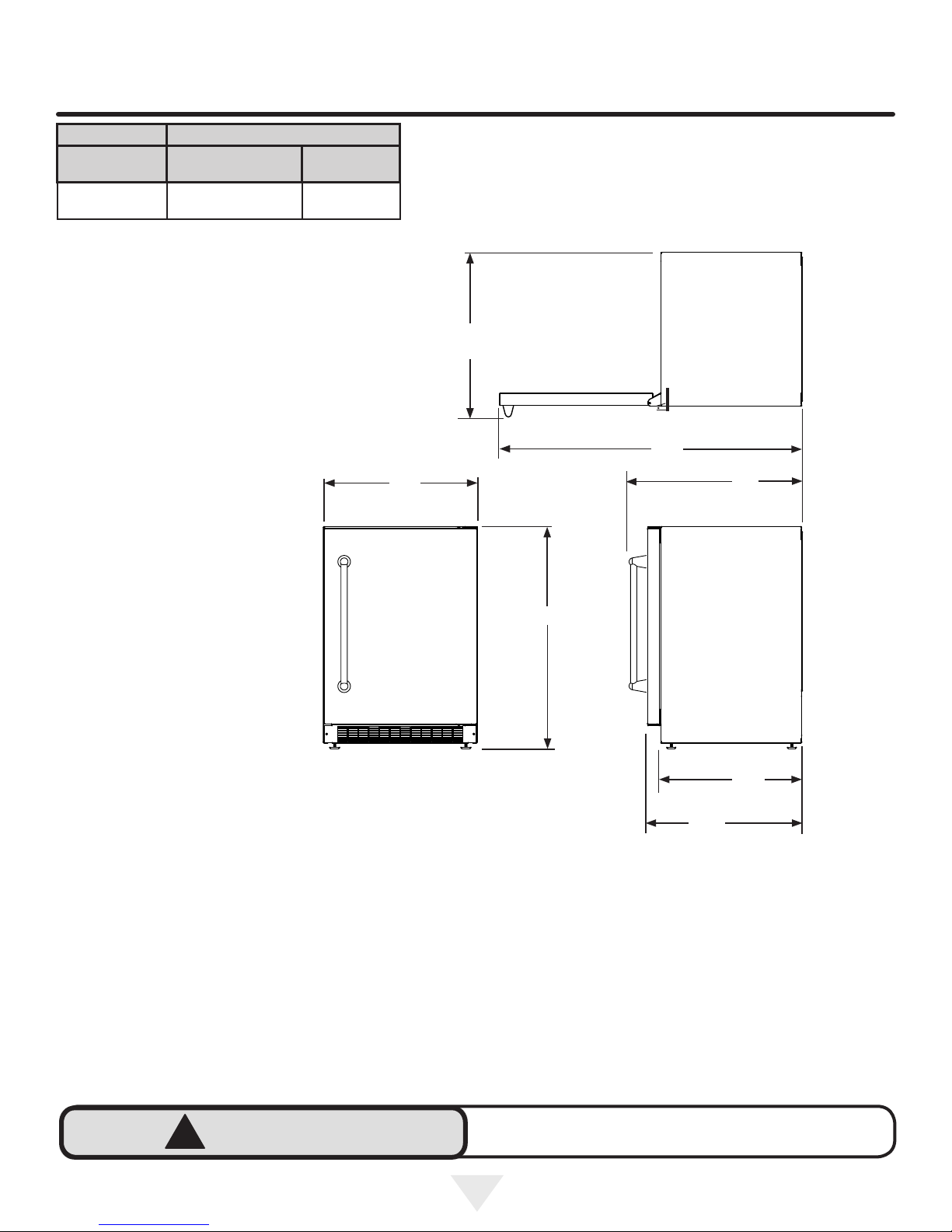
PRODUCT DIMENSIONS
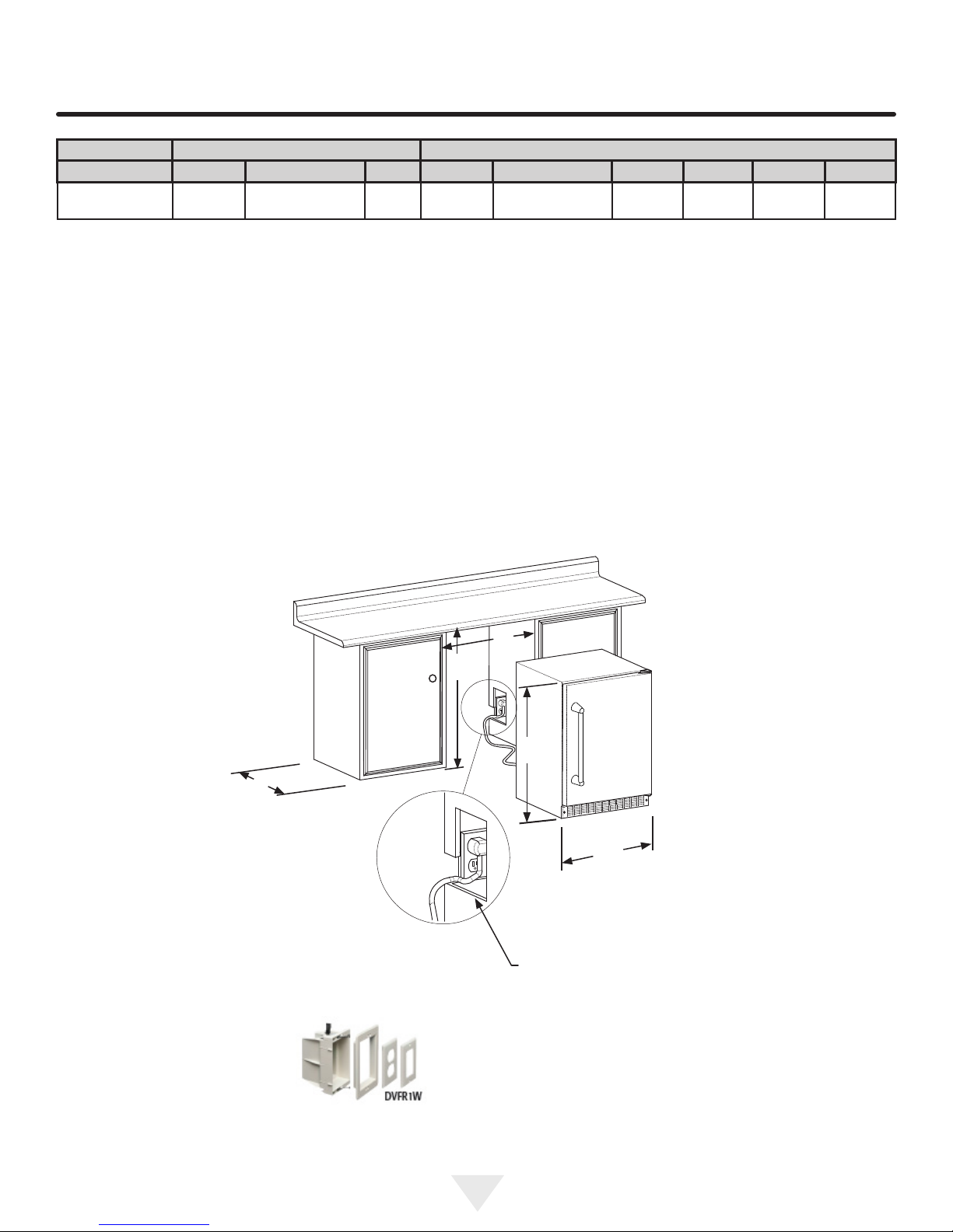
ROUGH-IN OPENING DIMENSIONS CABINET DIMENSIONS
MODEL "A" "B" "C" "D" "E" "F" "G" "H" "J"
TEOR24-E
24"
(61 cm)
**34" to 35"
(86.4 to 88.9 cm)
*
237⁄8"
(60.7 cm)
333⁄4" to 343⁄4"
(85.7 to 88.3 cm)
2323⁄32"
(60.2 cm)
269⁄16"
(67.5 cm)
4613⁄32"
(117.9 cm)
(67.5 cm)
269⁄16"
"C"
Figure 9a
Figure 10
"A"
"B"
Figure 9
"E"
"D"
If necessary to gain clearance inside the rough-in
opening a hole can be cut through the adjacent cabinet and the power cord routed through this hole to a
power outlet. Another way to increase the available
opening depth is to recess the power outlet into the
rear wall to gain the thickness of the power cord plug.
Not all recessed outlet boxes will work for this application as they are too narrow, but a recessed outlet box
equivalent to Arlington #DVFR1W is recommended for
this application, (see Figure 10).
8
Page 9
PRODUCT DATA
MODEL
TEOR24-E 115V/60Hz/15A
ELECTRICAL
REQUIREMENTS #
PRODUCT DIMENSIONS
PRODUCT
WEIGHT
140 lbs
(63.6 kg)
"J"
"H"
"D"
* Depth dimension of rough-in opening may vary depending on each individual installation. To recess entire door "F"
dimension plus 1" (2.5 cm) for thickness of power cord plug
is required.
"E"
Figure 11
"G"
211⁄2"
(54.6 cm)
"F"
** Minimum rough-in opening required is to be larger than
the adjusted height of the cabinet.
# A grounded 15 amp dedicated circuit is required. Follow
all local building codes when installing electrical and appliance.
!
WARNING
Floor mount Anti-tip Bracket must be installed for freestanding applications. Not required for built in applications.
9
Page 10
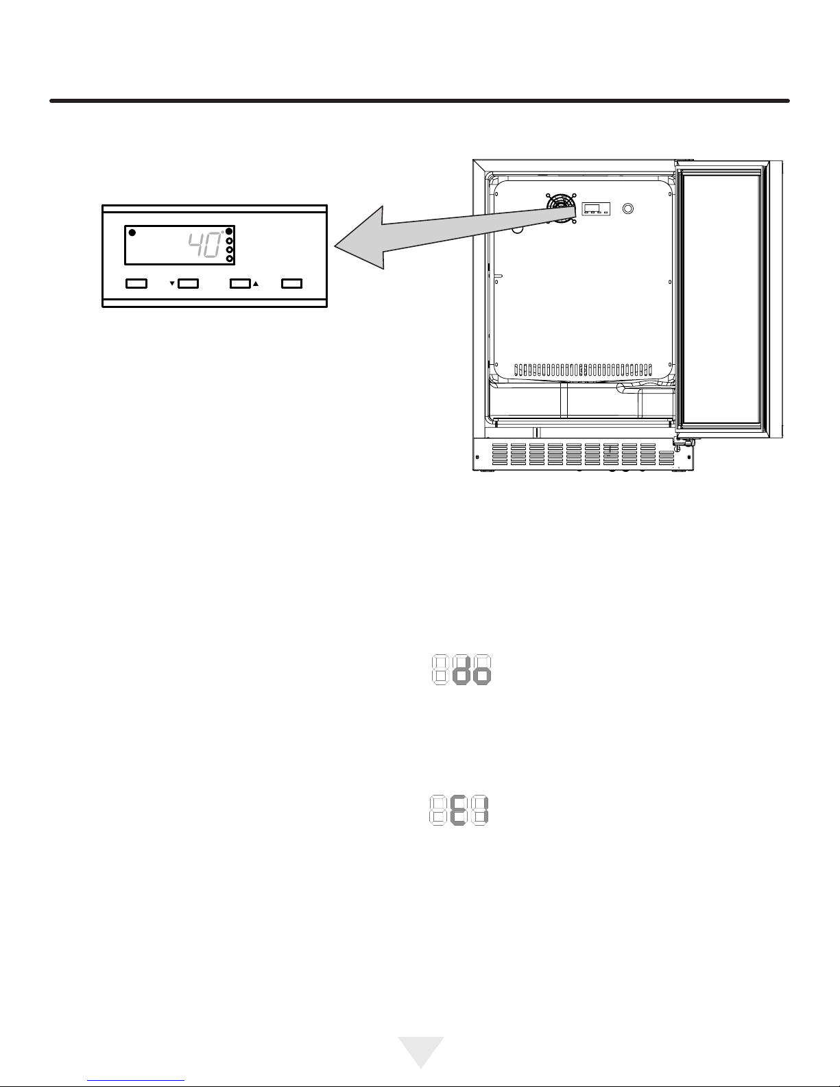
Alarm
USING YOUR ELECTRONIC CONTROL
F
Set
Press and Hold Press and Hold
Colder Warmer
ON/OFF
Figure 12
close-up of
control
Starting your refrigerator
Plug the refrigerator power cord into a wall outlet. Your
refrigerator will begin cooling after power is applied.
If your refrigerator does not start, check that the refrigerator
is turned on and the set temperature is cold enough.
Turning your refrigerator ON or OFF
If the refrigerator is on, the refrigerator temperature will be
shown on the display. To turn the refrigerator off, press and
hold the "ON/OFF" button for three (3) seconds. "OFF" will
appear on the display.
If the refrigerator is not on, "OFF" will be shown on the
display. To turn the refrigerator on, press and hold the "ON/
OFF" button for three (3) seconds. The refrigerator temperature will be shown on the display.
Set temperature
To set the refrigerator temperature, press and hold the
"SET" button. When the "SET" button is pressed, the
display will show the set temperature. While holding the
"SET" button, press the "WARMER" or "COLDER" buttons
to adjust set temperature.
Figure 13
Alarms
Your electronic control will monitor refrigerator function and
alert you with a series of audible and visual alarms.
• Door Ajar Alarm: If the door has been left
open for over ve (5) minutes, the alarm
will sound in one (1) second intervals. The
display panel will ash "do" and the Alarm LED located at
the top left of the display below the word "Alarm" will be illuminated. This will stop as soon as the door is closed.
Refrigerator operation
The available temperature range of the refrigerator is 34° to
42°F (1° to 6° C).
It may take up to 24 hours for your refrigerator to reach
desired temperature. This will depend on amount of content
loaded and number of door opening and closings.
For best results allow refrigerator to "pull down" to desired
set temperature before loading. Once contents are loaded,
allow at least 48 hours for temperature to stabilize before
making any adjustments to the set temperature.
• Temperature Sensor Fault: If the control-
ler detects that the temperature sensor is
not properly functioning, a temperature
sensor alarm will sound in one (1) second intervals. "E1"
will ash on the display panel and the Alarm LED located
at the top left of the display below the word "Alarm" will be
illuminated. Please call Twin Eagles Customer Service or
your dealer if this error code is displayed.
Alarm Mute
Press any key to mute the audible portion of an alarm.
NOTE-This action will only mute the alarm. If the condition that caused the alarm continues, the alarm code will
continue to ash and will sound for 20 seconds every 60
minutes.
10
Page 11
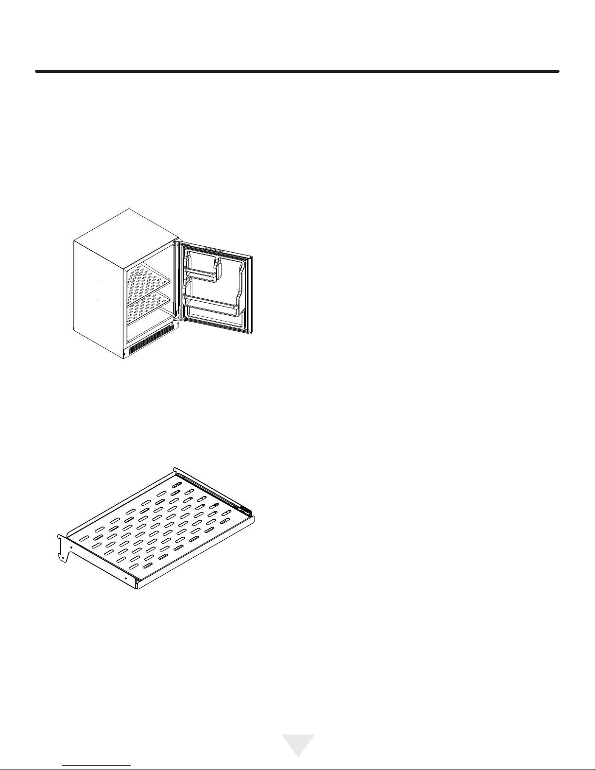
SHELVING CONFIGURATIONS
Loading Tips and Suggestions
Your appliance is equipped with a cantilever shelf system
which provides maximum adjust ability and customizing of
the shelving arrangements listed below.
24" (61 cm) Wide Models:
With a solid door and door racks. Figure 14.
Figure 14
(2) perforated slide out shelf (See Figure 15)..
(1) full width door storage rack.
(1) half width door storage rack.
Figure 15
perforated slide out shelf
11
Page 12
SHELVING CONFIGURATIONS
!
CAUTION
Never try to move a loaded shelf, remove everything from
the shelf before moving. Use both hands when moving the
shelf.
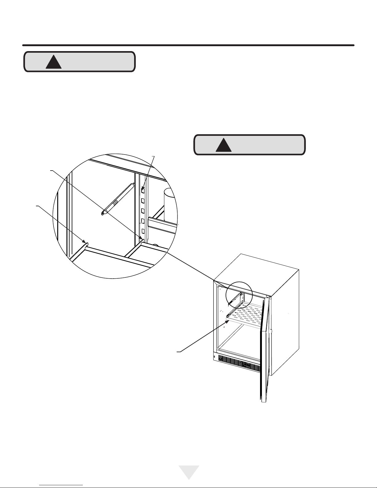
Shelf support
slot
Installed shelf
tang
Rear tang
(hook) on
shelf
To Add or Remove a Shelf
Remove stored product from the shelf. Do not try to remove
a loaded shelf from the appliance. Grasp the shelf front with
both hands, rotate the front upward and lift out. (See Figure
16). To install a shelf insert the shelf in the appliance and
insert the top hooks into the shelf support slots and drop
the shelf down so the hooks drop over the bottom of the
slots.
!
CAUTION
Make sure your cantilever shelf is secure on the shelf supports by pressing down on the shelf before loading.
Figure 16a
Grasp the shelf by the front with
both hands and rotate the front
of the shelf up, then lift the shelf
up and remove the shelf from the
shelf ladders.
Figure 16
12
Page 13
CARE AND CLEANING
Front Grille
Be sure that nothing obstructs the required air ow openings in front of the cabinet. At least once or twice a year,
brush or vacuum lint and dirt from the front grille area (see
page 4).
!
CAUTION
SHOCK HAZARD: Disconnect electrical power from the
appliance before cleaning with soap and water.
Cabinet
The stainless steel cabinet can be washed with either a
mild soap and water and thoroughly rinsed with clear water.
See "Stainless Steel Maintenance" on page 15.
Interior
Wash interior compartment with mild soap and water. Do
NOT use an abrasive cleaner, solvent, polish cleaner or
undiluted detergent.
!
WARNING
Electrocution Hazard
• Never attempt to repair or perform maintenance on
the appliance until the main electrical power has been
disconnected. Turning the appliance control "OFF"
does not remove electrical power from the unit's wiring.
• Replace all parts and panels before operating.
Care of Appliance
1. Avoid leaning on the door, you may bend the door
hinges or tip the appliance.
2. Exercise caution when sweeping, vacuuming or mopping near the front of the appliance. Damage to the
grille can occur.
3. Periodically clean the interior of the appliance as
needed.
In the Event of a Power Failure
If a power failure occurs, try to correct it as soon as possible. Minimize the number of door openings while the
power is off so as not to adversely affect the appliance's
temperature.
Light assembly replacement
All models use LED lamps to illuminate the interior of the
appliance. This component is very reliable, but should one
fail, contact a qualied service technician for replacement
of the LED.
13
Page 14
CARE AND CLEANING
Outdoor Product Long-Term Storage / Winterization:
1. Time to Winterize, when the daily low ambient tempera-
ture is at or below 38°F (3.3°C).
!
CAUTION
Operation of the unit at ambient temperatures below the
recommended Winterization temperature will void your warranty.
2. Turn unit off, (see page 10)
3. Remove all contents.
4. If necessary, move the unit so you can gain access to
the rear of the product.
5. Unplug the unit from the power outlet.
6. It is also recommended that the power to the outlet be
turned-off if the circuit is not required for other items
during the Winter season.
7. When cleaning unit pay particular attention to any
cracks and crevices that may have accumulated dirt
and debris.
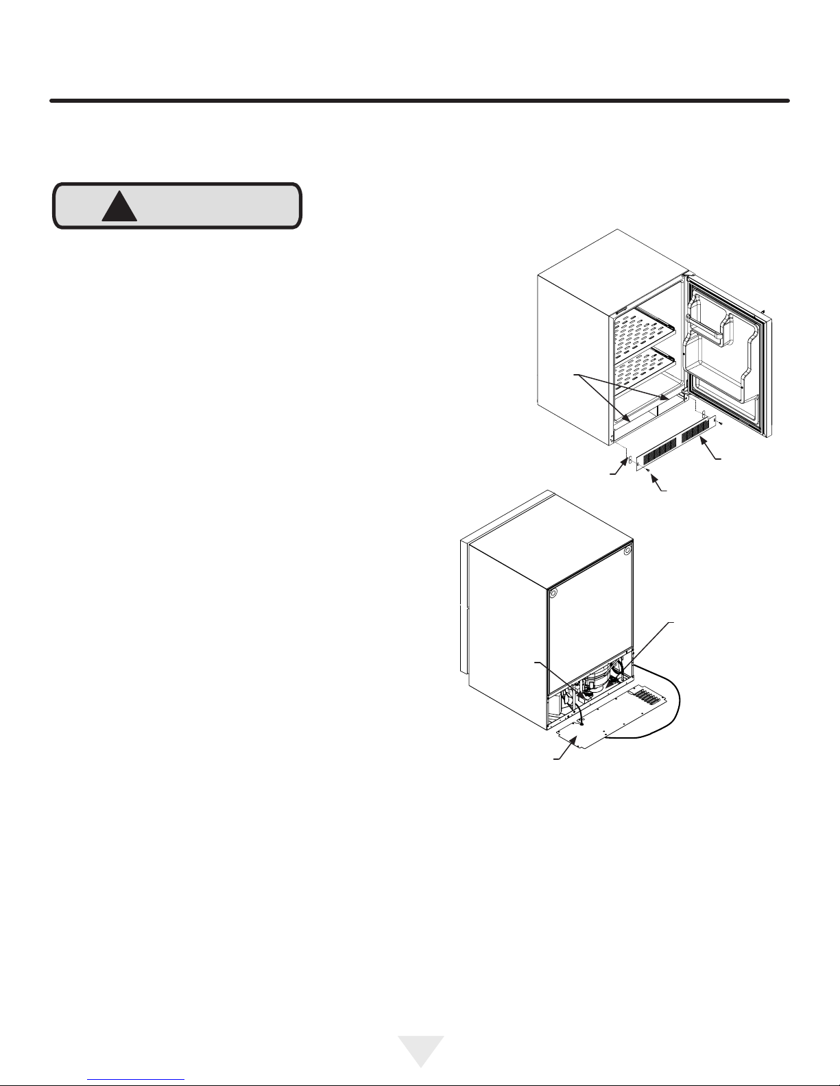
8. Remove the front toe-grille, (see Figure 17), and use a
brush and vacuum to clean dirt and debris from beneath the unit.
9. Thoroughly clean the toe-grille and re-install on the
unit. (See Figure 17).
10. Remove the rear access cover, (see Figure 18), and
use a brush and vacuum to clean dirt and debris from
the machine compartment.
• If the plastic defrost drain pan located under the
compressor contains water, use a sponge to
remove as much water as possible.
11. Thoroughly clean the rear access cover and re-install
on the unit.
12. Wipe down all interior surfaces with anti-bacterial
cleaner to be followed with clean rinse water to remove
any residual chemicals which could cause staining. Do
not use any abrasive cleaners or scouring pads.
13. Leave the door open and allow to completely dry out
before closing the door.
14. Thoroughly clean the door gasket with anti-bacterial
cleaner to be followed with clean rinse water to remove
any residual chemicals.
15. Thoroughly clean the exterior with a cleaner approved
for stainless steel. Do not use any abrasive cleaners or
scouring pads. See "Stainless Steel Maintenance" on
page 15.
16. Any mounting hardware / fasteners that are showing
signs of corrosion should be replaced.
17. Once the exterior has been thoroughly cleaned, you
may want to apply a coating of car wax to help protect
against spotting from moisture, dirt, and debris that
may accumulate on the surfaces during the Winterization period.
18. Do not place a cover on the unit, as this can trap condensation.
After completion of the above, you may choose to store the
unit indoors, although this is not required.
Clean out
behind
grille
Figure 17
Grille
Spacer
Remove screw from
each end of grille
Soak up
water from
plastic drain
pan if
necessary
Figure 18
Access cover
Clean out
debris
Remove screws
around perimeter
of access cover.
Start-Up After Long-Term Storage:
1. If stored outside, it is recommended that the unit again
be thoroughly inspected per the storage instructions
above to address any dirt or debris from the weather
and/or animals/insects.
2. Connect the unit to electrical power.
3. Turn unit on and conrm your desired control settings.
4. Allow 24-hrs for the unit to stabilize before loading
contents.
14
Page 15

STAINLESS STEEL MAINTENANCE AND ENERGY SAVING TIPS
Background
Stainless steel does not stain, corrode, or rust as easily as
ordinary steel, but it is not stain or corrosion proof. Stainless steels can discolor or corrode if not maintained properly.
Stainless steels differ from ordinary carbon steels by the
amount of chromium present. It is this chromium that
provides an invisible protective lm on the surface called
chrome-oxide. This protective chrome-oxide lm on the
surface can be damaged or contaminated, which may
result in discoloration, staining, or corrosion of the base
metal.
Care & Cleaning
Routine cleaning of the stainless steel surfaces will serve to
greatly extend the life of your product by removing contaminants. This is especially important in coastal areas which
can expose the stainless to severe contaminants such as
halide salts, (sodium chloride).
NOTE
Stainless steel products should never be installed, or stored
in close proximity to chlorine chemicals.
Whichever cleaning product you chose, it should be used
in strict accordance with the instructions of the cleaner
manufacturer.
Energy saving tips:
It is strongly recommended to periodically inspect and thoroughly clean crevices, weld points, under gaskets, rivets,
bolt heads, and any locations where small amounts of liquid
could collect, become stagnant, and concentrate contaminates. Additionally, any mounting hardware that is showing
signs of corrosion should be replaced.
Frequency of cleaning will depend upon the installation
location, environmental, and usage conditions.
Choosing a Cleaning Product
The choice of a proper cleaning product is ultimately that
of the consumer, and there are many products from which
to choose. Depending upon the type of cleaning and the
degree of contamination, some products are better than
others.
Typically the most effective and efcient means for routine
cleaning of most stainless steel products is to give the surfaces a brisk rubbing with a soft cloth soaked in warm water
and a gentle detergent, or mild mixture of ammonia. Rubbing should, to the extent possible, follow the polish lines of
the steel, and always insure thorough rinsing after cleaning.
Although some products are called "stainless steel cleaners," some may contain abrasives which could scratch the
surface, (compromising the protective chrome-oxide lm),
and some many contain chlorine bleach which will dull,
tarnish or discolor the surface if not completely removed.
After the stainless surfaces have been thoroughly cleaned,
a good quality car wax may be applied to help maintain the
nish.
The following suggestions will minimize the
cost of operating your refrigeration appliance.
1. Do not install your appliance next to a hot appliance
(cooker, dishwasher, etc.), heating air duct, or other
heat sources.
2. Install product out of direct sunlight.
3. Ensure the front grille vents at front of appliance beneath door are not obstructed and kept clean to allow
ventilation for the refrigeration system to expel heat.
4. Plug your appliance into a dedicated power circuit. (Not
shared with other appliances).
5. When initially loading your new product, or whenever
large quantities of warm contents are placed within
refrigerated storage compartment, minimize door
openings for the next 12 hours to allow contents to pull
down to compartment set temperature.
6. Maintaining a relatively full storage compartment will
require less appliance run time than an empty compartment.
7. Ensure door closing is not obstructed by contents
stored in your appliance.
8. Allow hot items to reach room temperature before placing in product.
9. Minimize door openings and duration of door openings.
10. Use the warmest temperature control set temperature
that meets your personal preference and provides the
proper storage for your stored contents.
11. When on vacation or away from home for extended pe-
riods, set the appliance to warmest acceptable tem perature for the stored contents.
12. Set the control to the “off” position if cleaning the
appliance requires the door to be open for an extended
period of time.
15
Page 16
DOOR ALIGNMENT AND OBTAINING SERVICE
Door alignment:
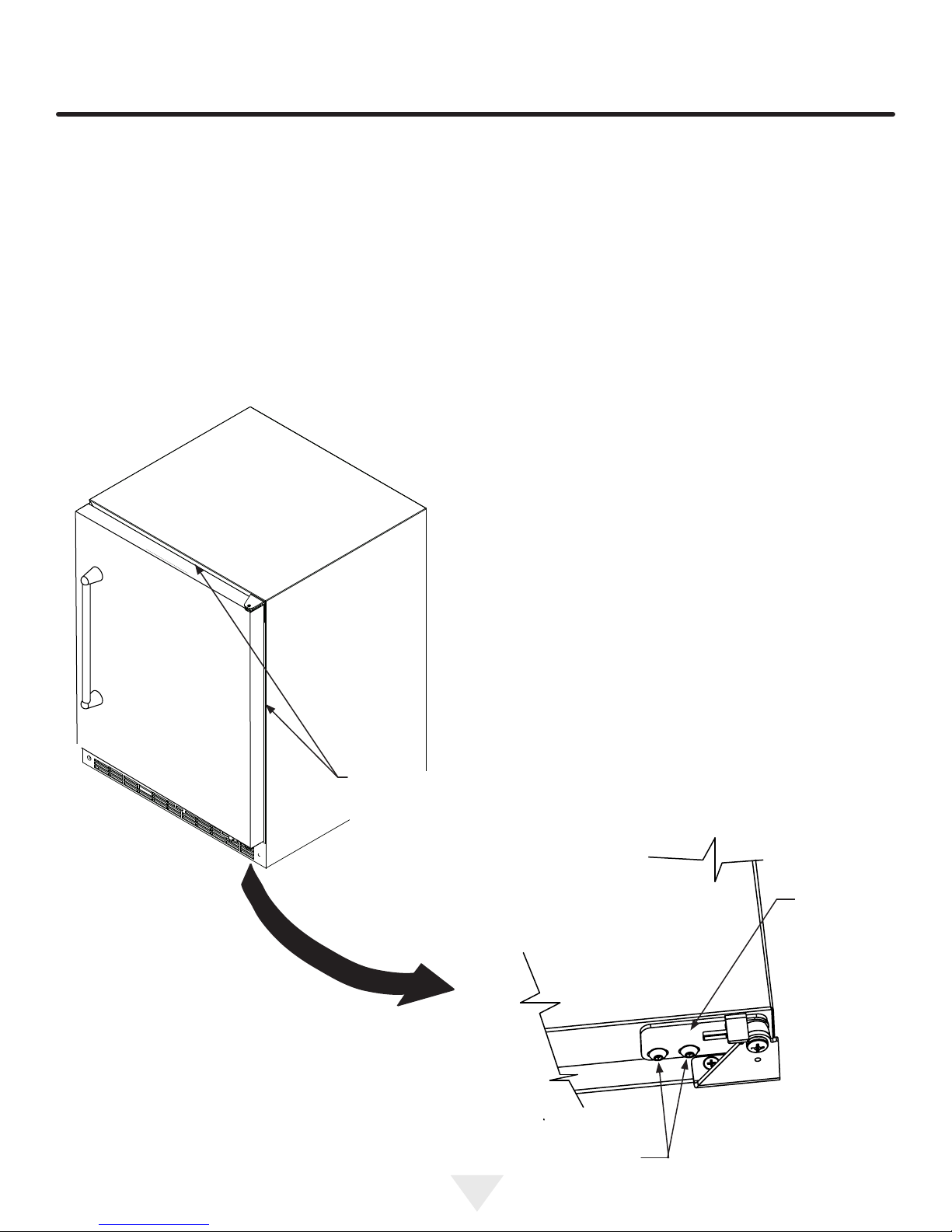
The door should be parallel to the sides and top of the appliance. If alignment is necessary the door may be adjusted
by loosening the 2 screws which secure the door adjust-
ment bracket on the bottom of the door (see Figure 19a)
and adjusting the door side to side. Use a 5⁄32” allen wrench
for this procedure. (See Figure 19 below). When nished
aligning the door, tighten the screws securely.
Figure 19
Door should be
parallel to top
and sides of the
appliance.
Door
adjustment
bracket
Bottom
of door
Figure 19a
Loosen (don't remove)
these two screws.
16
Page 17
TROUBLESHOOTING AND OBTAINING SERVICE
If You Do Need Service
If you do need service, contact your dealer or Twin Eagles.
In any correspondence, refer to the service number and
serial number of your ice machine which is located on the
upper left hand side of the wall liner. Retain your proof of
purchase. You may want to record these numbers in Table
A below.
How to Obtain Service
If trouble occurs during normal operation, rst check the
troubleshooting guide on page 17 to see if any of these
simple steps may correct the problem. If service becomes
necessary:
1. If the product is within the rst year warranty period,
please call Twin Eagles Customer Service at (562) 802-
3488 for directions on how to obtain warranty coverage
in your area.
2. If the product is outside of the rst year warranty
period, Twin Eagles Customer Service can provide
recommendations of service centers in your area.
3. In all correspondence regarding service, be sure to
give the service number, serial number, located on your
product’s serial plate, and proof of purchase.
4. Try to have information or description of the nature of
the problem, how long the ice machine has been running, the room temperature, water temperatures, and
any additional information that may be helpful in quickly
solving the problem.
For Your Records
Date of Purchase
Dealer’s name
Dealer’s Address
Dealer’s City
Dealer’s State
Dealer’s Zip Code
Appliance Serial Number
Appliance Service Number
Date Warranty Card Sent (Must
be within 10 days of purchase).
Table A
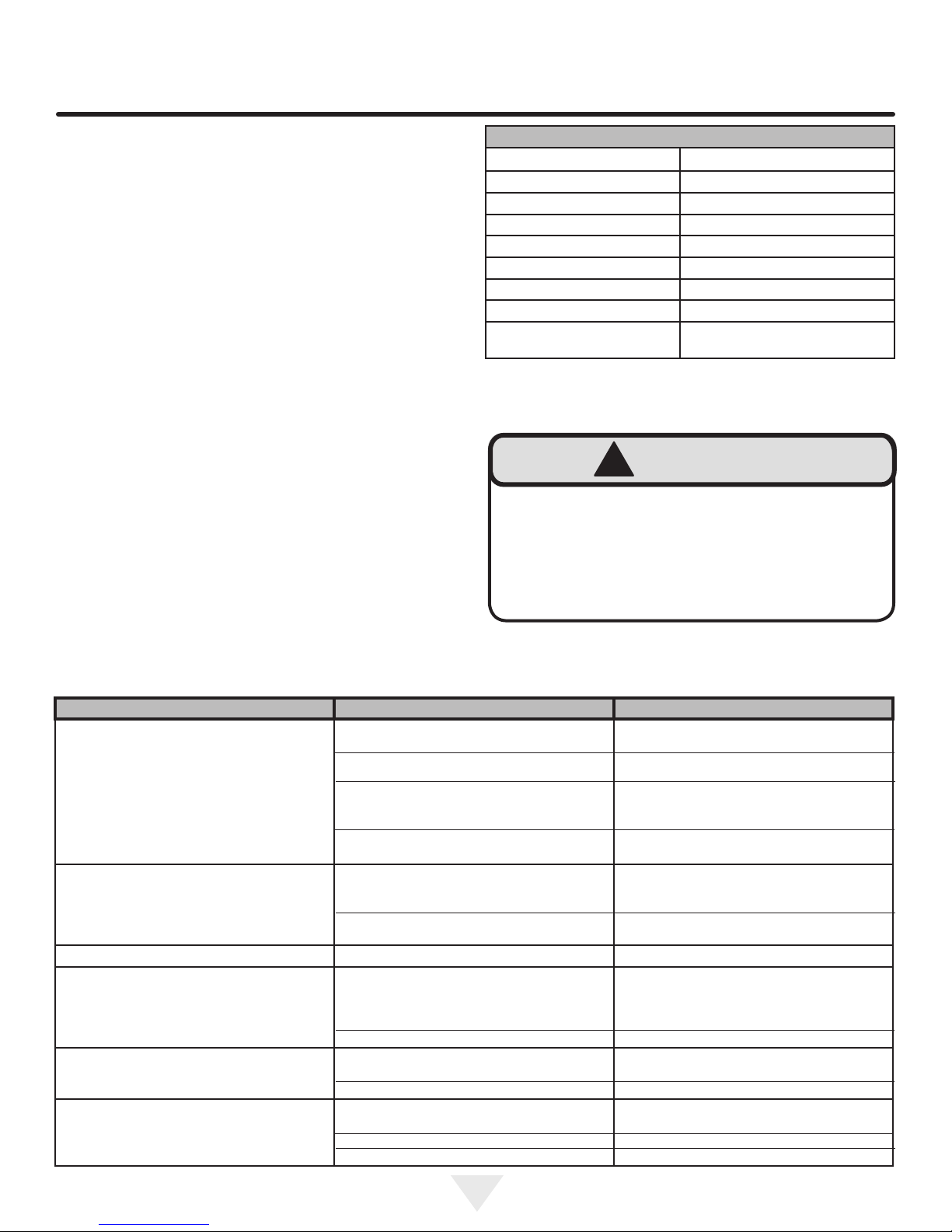
!
WARNING
Electrocution Hazard
• Never attempt to repair or perform maintenance on
the appliance until the main electrical power has been
disconnected. Turning the appliance control "OFF"
does not remove electrical power from the unit's wiring.
• Replace all parts and panels before operating.
Problem Possible Cause Remedy
Appliance not cold enough
(See “Adjusting the temperature" on page 10)
Appliance too cold
(See “Adjusting the Temperature” on page 10)
No interior light. • Failed LED light assembly or light switch. • Contact a qualied service technician.
Light will not go out when door is closed • Door not activating light switch.
Noise or Vibration • Appliance not level
Appliance will not run. • Appliance turned off
• Control set too warm
• Content temperature not stabilized.
• Excessive usage or prolonged door openings.
• Airow to front grille blocked.
• Door gasket not sealing properly.
• Control set too cold
• Door gasket not sealing properly.
• Failed light switch
• Fan hitting tube obstruction.
• Power cord not plugged in.
• No power at outlet.
• Adjust temperature colder. Allow 24 hours
for temperature to stabilize.
• Allow temperature to stabilize for at least
24 hours.
• Airow must not be obstructed to front
grille. See “clearances” on
page 4.
• Check door alignment and/or replace door
gasket.
• Adjust temperature warmer.
Allow 24 hours for temperature to
stabilize.
• Check door alignment and/or replace door
gasket.
• Appliance not level, level appliance, (See
page 4, “leveling legs”)
• Verify the door is aligned properly, refer to
page 16 for instructions.
• Contact a qualied service technician.
• Level appliance, see “Leveling Legs” on
page 4.
• Contact a qualied service technician.
• Turn appliance on. See “Starting your appliance” on page 10.
• Plug in power cord.
• Check house circuit.
17
Page 18

WARRANTY
Entire Product
Limited One Year Parts and Labor Warranty
Twin Eagles warrants that it will supply all necessary parts
and labor to repair or replace in the end user’s home or
ofce, any component which proves to be defective in material or workmanship, subject to the condition and exclusions stated below, for a period of one year from the date of
purchase by the end user.
Additional Second Through Fifth Year
Limited Parts Only Warranty
During the four years following expiration of the one year
limited warranty, Twin Eagles will supply replacement parts
for the hermetically sealed refrigeration system which
consists of the compressor, condenser, drier, accumulator,
bypass valve, connecting tubing and the evaporator that
are proven to be defective due to workmanship or materials
subject to the conditions and exclusions below.
The above warranties do not cover:
• Shipping costs of replacement parts or returned defective parts.
• Customer education or instructions on how to use the
appliance.
• Any content loss due to product failure.
• Removal or installation of product.
Nor do the above warranties cover failure of this product or
its components due to:
• Transportation or subsequent damages.
• Commercial use or use other than normal household or
small ofce.
• Improper installation, misuse, abuse, accident or alteration, use of wiring not conforming to electrical codes,
low or high voltages, failure to provide necessary maintenance, or other unreasonable use.
Parts or Service
Not Supplied or Designated by Twin Eagles
The above warranties also do not apply if:
• The original bill of sale, deliver date, or serial number
cannot be veried.
• Defective parts are not returned for inspection if so
requested by Twin Eagles.
• The refrigeration equipment is not in the possession of
the original end use purchaser.
The warranties set forth herein are the only warranties
extended by Twin Eagles. Any implied warranties, including the implied warranty of merchantability, are limited to
the duration of these express warranties. In no event shall
Twin Eagles be liable for any consequential or incidental
damages or expenses resulting from breach of these or any
other warranties, whether express or implied.
Some states do not allow the exclusion or limitation of consequential damages or a limitation on how long an implied
warranty lasts, so the above exclusion or limitation may not
apply to you. This warranty gives you specic legal rights
and you may have other rights that may vary from state to
state.
No person, rm, or corporation is authorized to make any
other warranty or assume any other obligation for Twin
Eagles. These warranties apply only to products used in
any of the fty states of the United States and the District of
Columbia.
To obtain performance of this warranty, report any defects
to:
Twin Eagles
13259 E. 166th St.
Cerritos, CA 90703
(562) 802-3488
18
Page 19
13259
19
Page 20
41014051 revA
4/24/15
20
 Loading...