

Page 1
MODEL T050
CEILING EXHAUST FAN
READ AND SAVE THESE INSTRUCTIONS
WARNING
TO REDUCE THE RISK OF FIRE, ELECTRIC SHOCK, OR INJURY TO PERSONS,
OBSERVE THE FOLLOWING:
1. Use this unit only in the manner intended by the manufacturer. If you have questions,
contact the manufacturer at the address or telephone number listed in the warranty.
2. Before servicing or cleaning unit, switch power off at service panel and lock the
service disconnecting means to prevent power from being switched on accidentally.
When the service disconnecting means cannot be locked, securely fasten a prominent warning device, such as a tag, to the service panel.
3. Installation work and electrical wiring must be done by a qualified person(s) in
accordance with all applicable codes and standards, including fire-rated construction codes and standards.
4. Sufficient air is needed for proper combustion and exhausting of gases through the
flue
(chimney
equipment manufacturer's guideline and safety standards such as those published
by the National Fire Protection Association (NFPA), and the American Society for
Heating, Refrigeration and Air Conditioning Engineers (ASHRAE), and the local
code authorities.
) of fuel-burning equipment to prevent backdrafting. Follow the heating
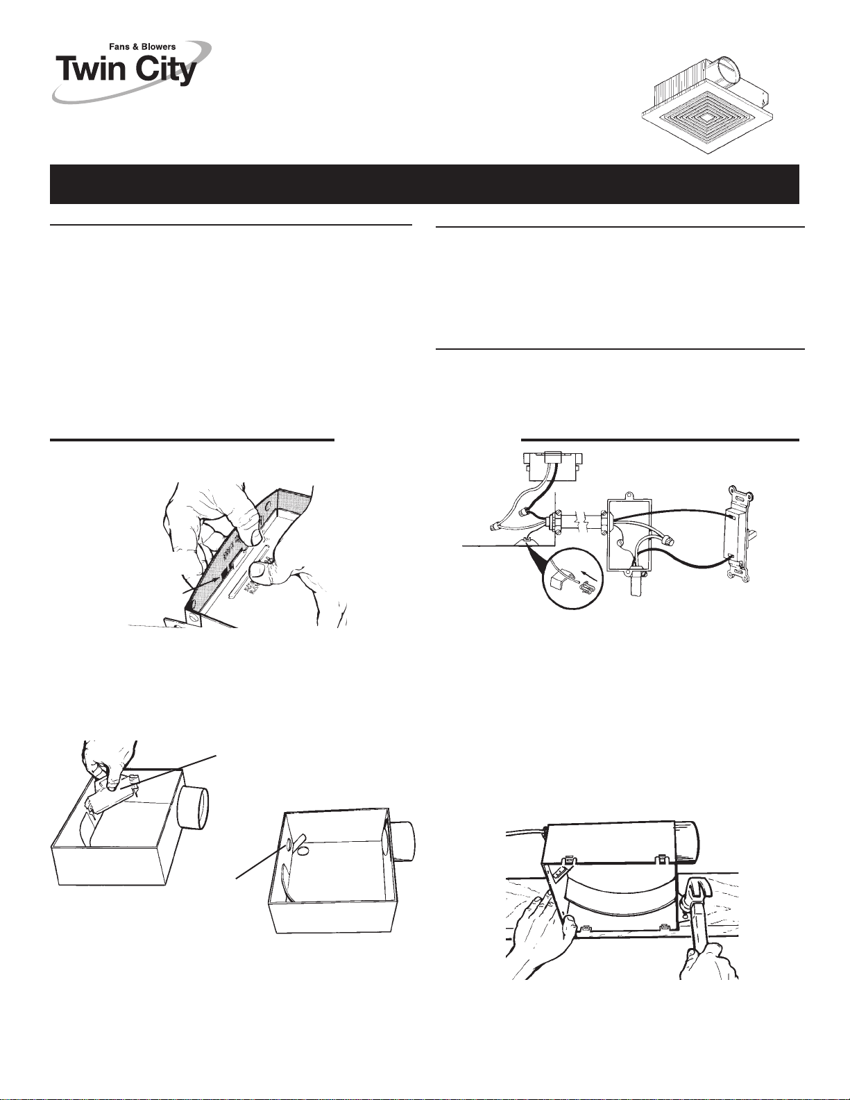
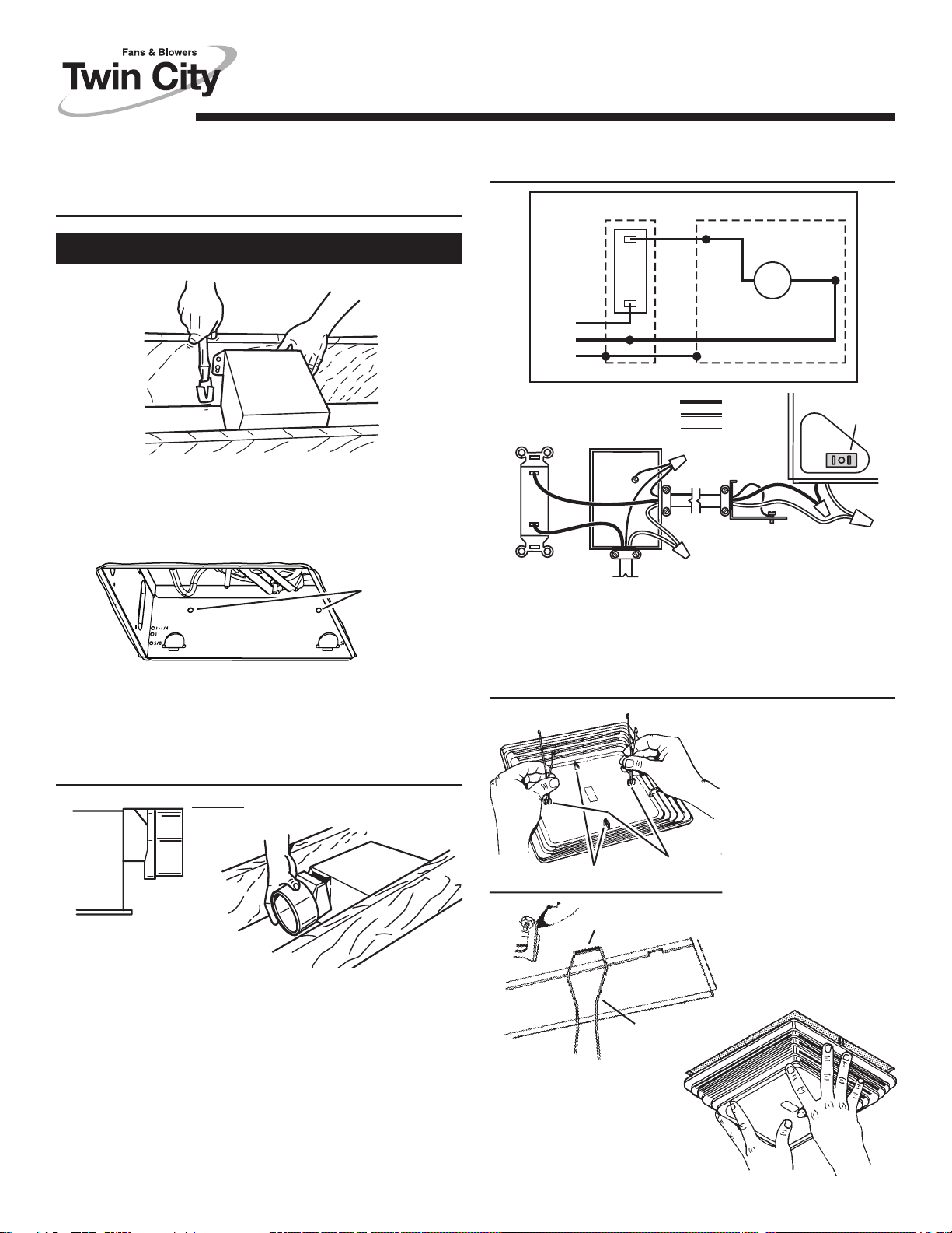
INSTALLATION
SCREWDRIVER
SLOT
WARNING
5. When cutting or drilling into wall or ceiling, do not damage electrical wiring and other
hidden utilities.
6. Ducted fans must always be vented to the outdoors.
7. This unit may be used over a tub or shower enclosure when installed in a GFCI
protected branch circuit.
8. If this unit is to be installed over a tub or shower, it must be marked as appropriate for
the application.
9. Never place a switch where it can be reached from a tub or shower.
10. This unit must be grounded.
CAUTION
1. For general ventilating use only. Do not use to exhaust hazardous or explosive
materials and vapors.
2. To avoid motor bearing damage and noisy and/or unbalanced impellers, keep
drywall spray, construction dust, etc. off power unit.
3. Please read specification label on product for further information and require-
ments.
RECEPTACLE
SWITCH BOX
HOUSING
GROUND
WIRECLIP
DETAIL
LINE IN
1. Remove motor plate from housing by pushing down on rib in plate
while pulling out on side of housing. Motor plate may also be
removed by inserting a straight-blade screwdriver into slot in
housing and twisting screwdriver.
WIRING
COVER
HOUSING
FLAP
2. Remove wiring cover from housing by pulling straight out. Unit is
shipped ready to wire through the top of housing. To wire through
the side, bend housing flap to cover top hole and expose side hole.
DO NOT BREAK OFF FLAP. If flap breaks, plug unused hole
using standard electrical hole plug.
3. Turn off electrical power at service entrance and connect
power cable to housing using appropriate connector. Wire black
to black, white to white. Insert ground wire into grounding clip and
secure to emboss in housing. Push all wiring up into corner of unit
and replace wiring cover. Make sure cover holds housing flap in
place against side or top of housing. CAUTION: DO NOT ALLOW
WIRES TO EXTEND OUTSIDE OF WIRING BOX. Wire left
exposed will become pinched or cut when motor plate is
installed. Electrical shock may result.
4. Choose the location for your fan. For best performance, use the
shortest possible duct run and a minimum number of elbows. For
wall installations: Position unit so damper flap closes when unit is
off.
5. Use embossed measuring guides on side of housing to position
housing for proper wall or ceiling thickness. MAKE SURE HOUSING WILL BE FLUSH WITH FINISHED CEILING OR WALL. Nail
housing or stude joist using four nails to ensure a solid, quiet
installaltion.
Page 2
6. Install 3" round duct onto damper/duct connector. If rigid ductwork
is used, its seam should be positioned at top of damper/duct
connector. Tape the joint and extend ducting to a wall cap or roof
cap. Make sure the damper operates freely. Ceiling or wall can now
be finished.
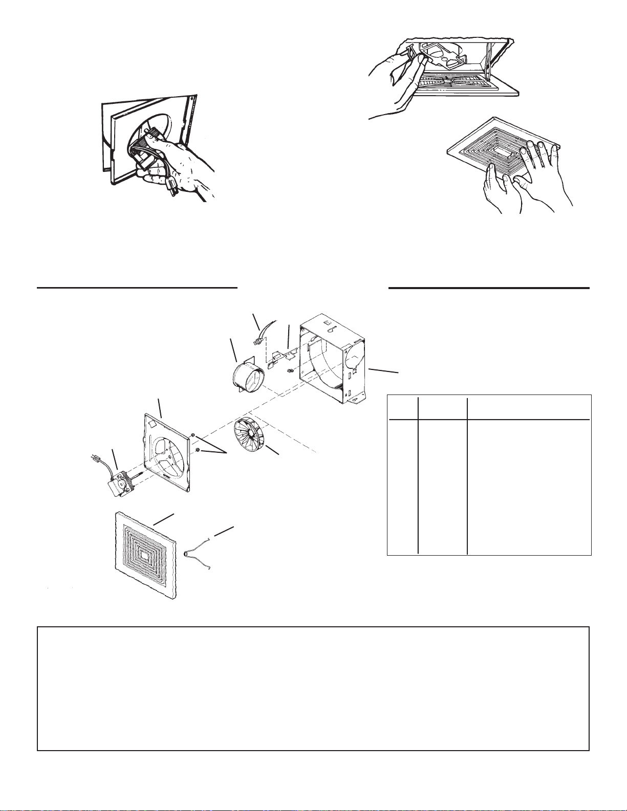
7. Replace the motor plate removed in Step 1. Insert two motor plate
tabs into slots in housing and then pivot motor plate up until third
tab on plate snaps into matching slot in housing. Make sure tabs
hold motor plate securely in place. Plug in motor.
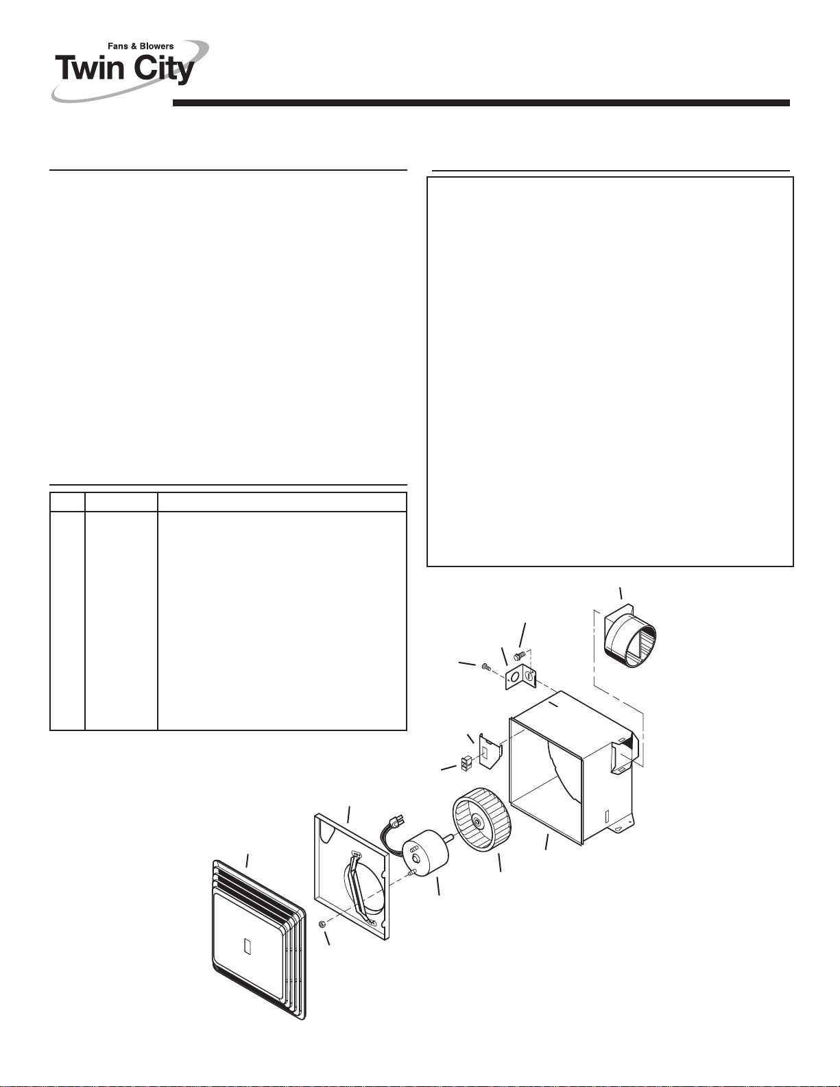
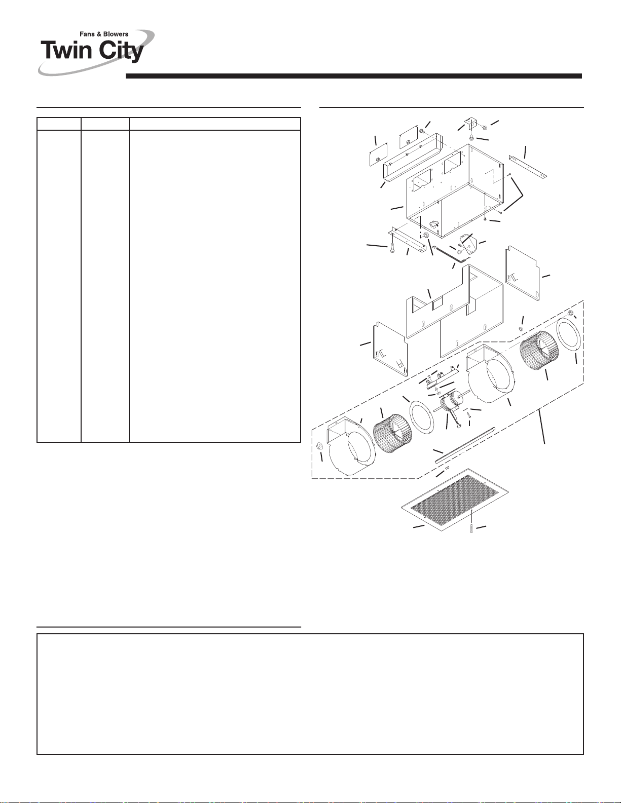
SERVICE PARTS
8
9
7
8. Squeeze grille springs together and insert springs into slots
in motor plate. Push grille up against ceiling or wall.
11
4
KEY
NO. PART NO. DESCRIPTION
1 99110752 Grille Only
3
6
5
1
2
Seller warrants to the original purchaser that the goods sold hereunder shall be free from defects in workmanship and material under normal use and service (except in those cases where the materials
are supplied by the buyer) for a period of one year from the date of original installation or eighteen (18) months from the date of shipment, whichever occurs first. The liability of seller under this warranty
is limited to replacing, repairing, or issuing credit (at cost, F.O.B. factory and at seller’s discretion) for any part or parts which are returned by buyer during such period provided that:
a. seller is notified in writing within ten (10) days following discovery of such defects by buyer, or within ten (10) days after such defects should reasonably have been discovered, whichever is less;
b. the defective unit is returned to seller, transportation charges prepaid by buyer.
c. payment in full has been received by seller or said products; and
d. seller’s examination of such unit shall disclose to its satisfaction that such defects have not been caused by misuse, neglec t, improper installation, repair, alteration, act of God, or accident.
No warranty made hereunder shall extend to any seller product whose serial number is altered, effaced or removed. Seller makes no warranty, express or implied, with respect to motors, switches, controls,
or other components of seller’s product, where such components are warranted separately by their respective manufacturers. THIS WARRANTY IS EXPRESSLY IN LIEU OF ALL OTHER WARRANTIES,
EXPRESS OR IMPLIED, WHETHER STATUTORY OR OTHERWISE, INCLUDING ANY IMPLIED WARRANTY OF MERCHANTABILITY OR FITNESS FOR A PARTICULAR PURPOSE. In no event shall
seller be liable to buyer for indirect, incidental collateral, or consequential damages of any kind. (BUYER’S FAILURE TO PAY THE FULL AMOUNT DUE WITHIN SIXTY (60) DAYS OF DATE OF INVOICE
SHALL OPERATE TO RELEASE SELLER FROM ANY AND ALL LIABILITY OR OBLIGATION ARISING PURSUANT TO ANY WARRANTY, EXPRESS OR IMPLIED, WHETHER STATUTORY OR
OTHERWISE, INCLUDING ANY IMPLIED WARRANTY OR MERCHANTABILITY OR FITNESS FOR A PARTICULAR PURPOSE, MADE IN CONNECTION WITH ANY CONTRACT FORMED HEREUNDER. BUYER AGREES THAT SUCH FAILURE TO PAY SHALL CONSTITUTE A VOLUNTARY WAIVER OF ANY AND ALL SUCH WARRANTIES ARISING PURSUANT TO SUCH CONTACT.)
Limitation of Warranties and Claims
2 99140137 Grille Springs (2 Required)
97009346 Grille Assembly (Includes Key
Nos. 1 & 2)
3 99080254 Motor (T050)
4 98006791 Motor Plate
5 99110655 Blower Wheel
6 99260428 Nut #6-32 (2 Required)
7 97008632 Damper/Duct Connector
8 99270748 Receptacle
9 98006773 Wiring Cover
10 99390015 Ground Clip
11 97008319 Housing Assembly
Order replacement parts by part number - not key
number.
TWIN CITY FAN & BLOWER, 5959 Trenton Lane, Minneapolis, MN 55442
99042958B
Page 3
CEILING
VENTILATOR
READ AND SAVE THESE INSTRUCTIONS
MODEL • T080
Page 1
WARNING
TO REDUCE THE RISK OF FIRE, ELECTRIC SHOCK, OR INJURY TO PERSONS, OBSERVE THE FOLLOWING:
1. Use this unit only in the manner intended by the manufacturer. If
you have questions, contact the manufacturer at the address or
telephone number listed in the warranty.
2. Before servicing or cleaning unit, switch power off at service panel
and lock the service disconnecting means to prevent power from
being switched on accidentally. When the service disconnecting
means cannot be locked, securely fasten a prominent warning
device, such as a tag, to the service panel.
3. Installation work and electrical wiring must be done by a qualified person(s) in accordance with all applicable codes and standards, including fire-rated construction codes and standards.
4. Sufficient air is needed for proper combustion and exhausting of
gases through the flue (chimney) of fuel burning equipment to
prevent backdrafting. F ollow the heating equipment
manufacturer’s guideline and safety standards such as those
published by the National Fire Protection Association (NFPA),
and the American Society for Heating, Refrigeration and Air Conditioning Engineers (ASHRAE), and the local code authorities.
5. When cutting or drilling into wall or ceiling, do not damage electrical wiring and other hidden utilities.
WARNING
6. Ducted fans must always be vented to the outdoors.
7. If this unit is to be installed over a tub or shower, it must be
marked as appropriate for the application and be connected to a
GFCI (Ground Fault Circuit Interrupter) - protected branch circuit.
8. Never place a switch where it can be reached from a tub or
shower.
9. This unit must be grounded.
CAUTION
1. For general ventilating use only. Do not use to exhaust hazardous or explosive materials and vapors.
2. To avoid motor bearing damage and noisy and/or unbalanced
impellers, keep drywall spray, construction dust, etc. off power
unit.
3. Please read specification label on product for further information and requirements.
!
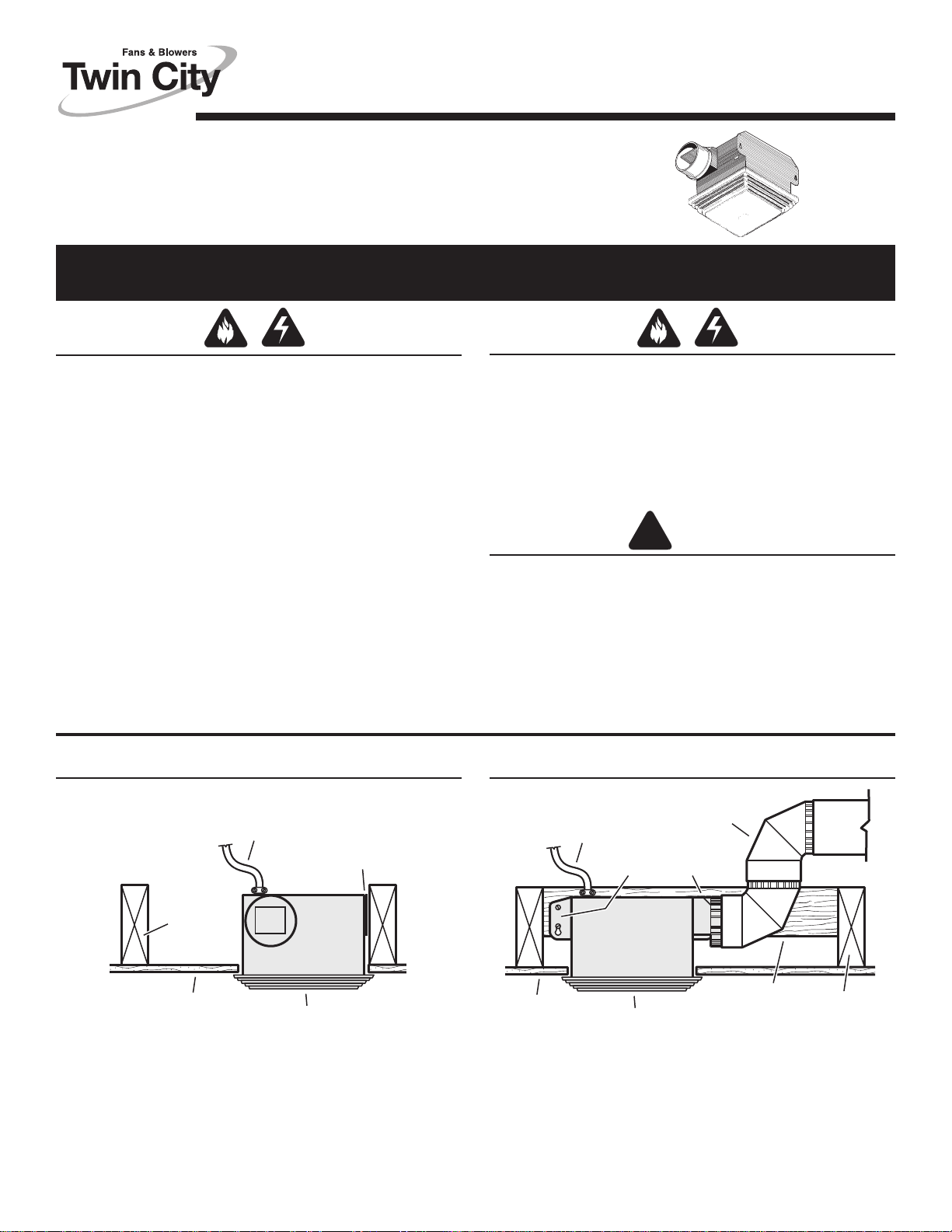
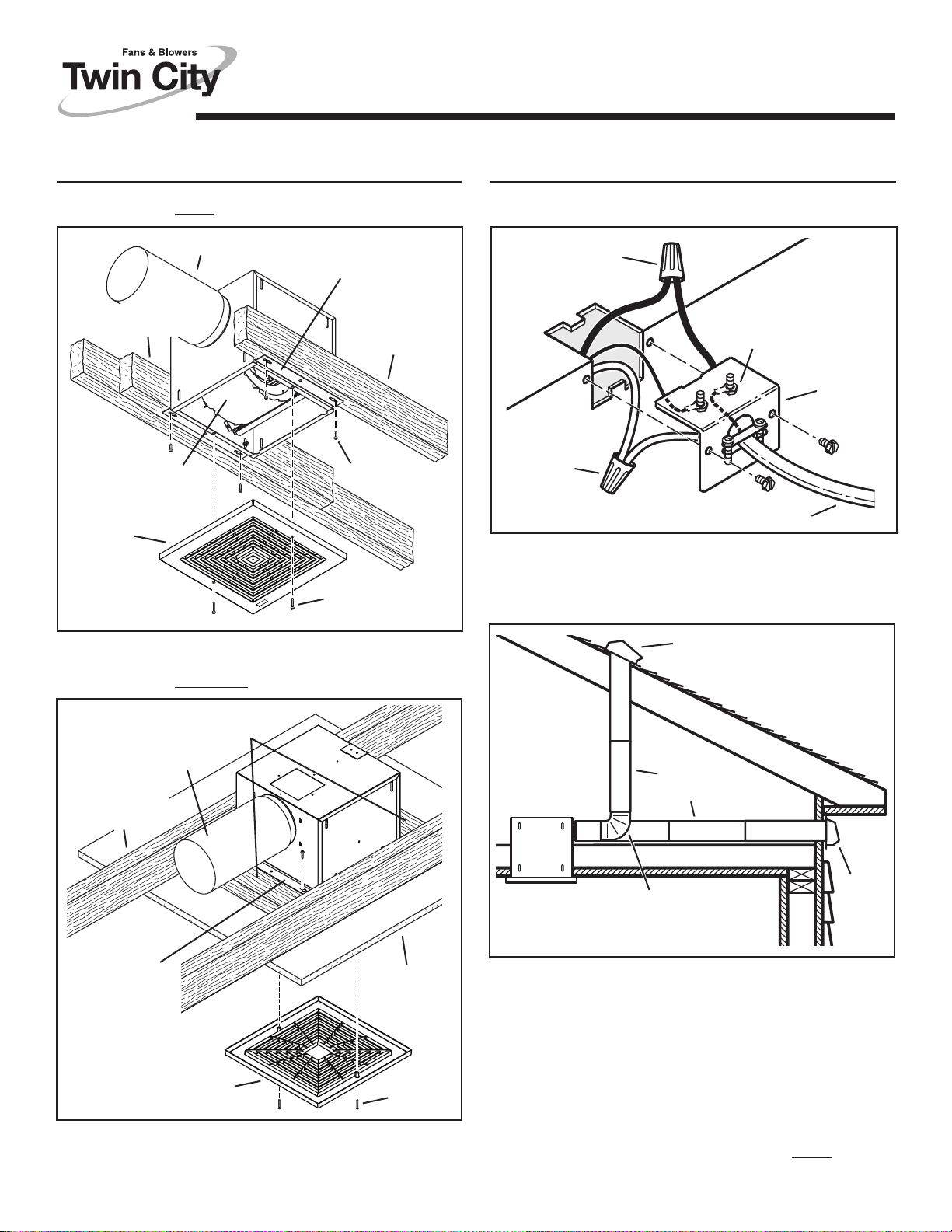
TYPICAL INSTALLATIONSTYPICAL INSTALLATIONS
4" ROUND
POWER CABLE
MOUNTING TABS
CEILING
JOIST
HOUSING
CEILING
MATERIAL
GRILLE
16”-ON-CENTER CEILING JOISTS
Housing mounted directly to joist.
POWER CABLE
MOUNTING TABS
HOUSING
CEILING
MATERIAL
GRILLE
24”-ON-CENTER CEILING JOISTS
Housing mounted to additional framing.
DUCT
ADDITIONAL
Installer: Leave this manual with the homeowner.
Homeowner: Use and Care information on page 4.
FRAMING
CEILING
JOIST
Page 4
MODEL • T080
Page 2
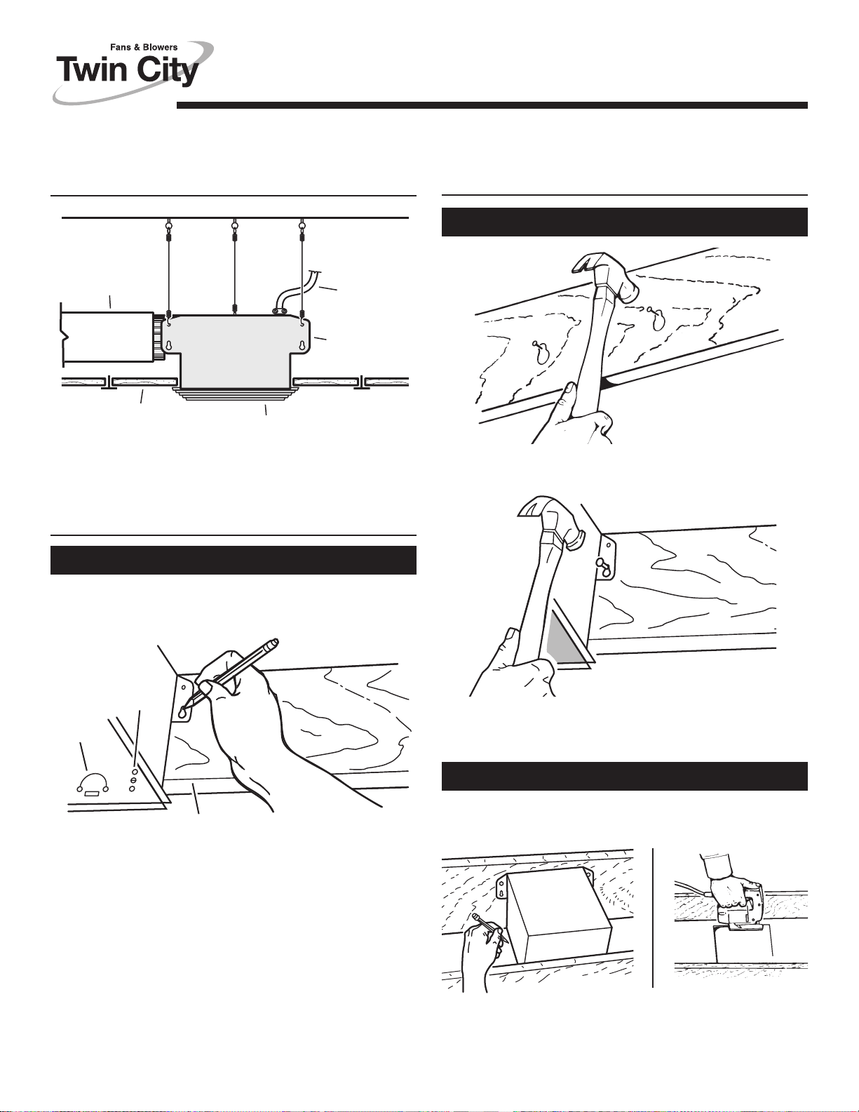
TYPICAL INSTALLATIONS
(continued)
4" ROUND
DUCT
SUSPENDED
CEILING MATERIAL
HOUSING
GRILLE
POWER
CABLE
MOUNTING
TAB
SUSPENDED CEILINGS
Housing hung with wires - 3-point mount.
INSTALL THE HOUSING
New Construction
INSTALL THE HOUSING
(continued)
New Construction
3. Set housing aside and drive nails partially into joist at the top of
both keyhole marks.
1. Choose the location for your fan in the ceiling. For best possible
performance, use the shortest possible duct run and a minimum
number of elbows.
HOLES
TAB
1-1/4
1
5/8
BOTTOM EDGE OF JOIST
2. Position mounting brackets against joist so that bottom
edge of housing will be flush with finished ceiling.
Additional positioning feature for 5/8”, 1”, & 1-1/4”
thick ceiling material:
Holes in corners of housing are labeled with various
ceiling material thicknesses. Position housing so bottom
edge of joist is visible through a matched set of holes.
The housing is now in the proper position for that ceiling
material thickness.
Additional positioning feature for 1/2” thick ceiling
material:
Bend two tabs, on side of housing, 90
housing until tabs contact underside of joist.
Mark the keyhole slot on both mounting brackets.
0
outward. Lift
4. Hang housing from nails and pound nails tight. To ensure a noisefree mount, pound another nail through the top hole of each
mounting tab.
Existing Construction
1. Choose the location for your fan in the ceiling. For best possible
performance, use the shortest possible duct run and a minimum
number of elbows.
2. In attic, position mounting brackets against joist. Trace outline of
housing on ceiling material.
3. Set housing aside and cut ceiling opening slightly larger than
marked.
Page 5
MODEL • T080
Page 3
INSTALL THE HOUSING
(continued)
Existing Construction
4. Place housing in opening so that its bottom edge is flush
with finished ceiling. Nail to joist through keyhole on both sides.
To ensure a noise-free installation, drive another nail through
the top hole of each mounting bracket.
ADDITIONAL
MOUNTING
HOLES
CONNECT THE WIRING
SCHEMATIC WIRING DIAGRAM
B L K
O N / OFF
S WITC H
B L K
LIN E
I N
ON / OFF SWITCH
(purchase separately)
W H T
G R D
S WITCH B O X
SWITCH BOX
120 VAC
LINE IN
W H T
G R D
1. Wire unit following diagram above. Run electrical cable as direct
as possible to unit. Do not allow cable to touch sides or top of
unit after installation is complete.
B L K
BLACK
WHITE
GROUND
(bare)
WIRING
PLATE
M
UNI T
W H T
RECEPTACLE
5. Additional mounting holes are provided for installations where
access from above is inconvenient or not possible. Nail or screw
housing directly to joists or framing.
INSTALL THE DUCTWORK
FLUSH
1. Snap the damper/duct connector onto housing. Make sure that
tabs on the connector lock into slots in housing. Top of damper/
duct connector should be flush with top of housing.
2. Connect 4” round duct to damper/duct connector and extend
duct to outside through a roof or wall cap. Check damper to
make sure that it opens freely. Tape all duct connections to make
them secure and air tight.
ATTACH THE GRILLE
1. Squeeze grille springs
toget her and insert
OPTIONAL TABS
SLOT IN
MOTOR PLATE
2. Push grille up
against ceiling.
SPRING
TABS
GRILLE
SPRING
springs into slots in motor plate.
NOTE: If desired, rotate
grille 90
springs to optional tabs.
o
and move
Page 6
MODEL • T080
Page 4
USE AND CARE
WARNING: DISCONNECT ELECTRICAL POWER SUPPLY AND
LOCK OUT SERVICE PANEL BEFORE CLEANING OR SERVICING THIS UNIT.
The motor is permanently lubricated. Do not oil or disassemble
motor.
TO CLEAN GRILLE:
CAUTION: Plastic parts can be cleaned with mild, soapy water (use
a mild detergent, such as dishwashing liquid) and dried with a soft
cloth. Do not use abrasive cloth, steel wool pads, or scouring
powders.
TO CLEAN FAN ASSEMBLY:
Unplug fan assembly. To remove motor plate: Find the single tab on
the motor plate (located next to the receptacle). Push up near motor
plate tab while pushing out on side of housing. Or insert a straightblade screwdriver into slot in housing (next to tab) and twist
screwdriver. Gently vacuum fan, motor and interior of housing.
METAL AND ELECTRICAL PARTS SHOULD NEVER BE IMMERSED IN WATER.
SERVICE PARTS
KEY PART NO. DESCRIPTION
1 97013576 Grille
2 97014926 Motor Plate
3 99080518 Motor (T080)
4 99020276 Impeller
5 99260425 Motor Nut (2 req.)
97015159 Blower Assembly (includes Key Nos. 2 thru
*
6 99270982 Receptacle
7 98009611 Wire Panel
97015170 Wire Panel Assembly (includes Key Nos. 6 & 7)
*
8 97014922 Housing
9 97003932 Damper/Duct Connector
10 98008868 Wiring Plate
11 99150575 Screw, #8-18 x .375
12 99150574 Ground Screw
Not shown assembled.
*
Order replacement parts by
“PART NO.” - not by “KEY NO.”
5) (T080)
2
WARRANTY
Seller warrants to the original purchaser that the goods sold hereunder shall be
free from defects in workmanship and material under normal use and service
(except in those cases where the materials are supplied by the buyer) for a period
of one year from the date of original installation or eighteen (18) months from the
date of shipment, whichever occurs first. The liability of seller under this warranty
is limited to replacing, repairing, or issuing credit (at cost, F.O.B. factory and at
seller’s discretion) for any part or parts which are returned by buyer during such
period provided that:
a. seller is notified in writing within ten (10) days following discovery of such defects by buyer, or within ten (10) days after su
been discovered, whichever is less;
b. the defective unit is returned to seller, transportation charges prepaid by buyer.
c. payment in full has been received by seller or said products; and
d. seller’s examination of such unit shall disclose to its satisfaction that such de-
fects have not been caused by misuse, neglect, improper installation, repair, alteration, act of God, or accident.
No warranty made hereunder shall extend to any seller product whose serial number is altered, effaced or removed. Seller makes no warranty, express or implied,
with respect to motors, switches, controls, or other components of seller’s product, where such components are warranted separately by their respective manufacturers.
THIS WARRANTY IS EXPRESSLY IN LIEU OF ALL OTHER WARRANTIES, EXPRESS OR IMPLIED, WHETHER STATUTORY OR OTHERWISE,
INCLUDING ANY IMPLIED WARRANTY OF MERCHANTABILITY OR FITNESS
FOR A PARTICULAR PURPOSE. In no event shall seller be liable to buyer for
indirect, incidental collateral, or consequential damages of any kind. (BUYER’S
FAILURE TO PAY THE FULL AMOUNT DUE WITHIN SIXTY (60) DAYS OF DATE
OF INVOICE SHALL OPERATE TO RELEASE SELLER FROM ANY AND ALL
LIABILITY OR OBLIGATION ARISING PURSUANT TO ANY WARRANTY, EXPRESS OR IMPLIED, WHETHER STATUTORY OR OTHERWISE, INCLUDING
ANY IMPLIED WARRANTY OR MERCHANTABILITY OR FITNESS FOR A PARTICULAR PURPOSE, MADE IN CONNECTION WITH ANY CONTRACT FORMED
HEREUNDER. BUYER AGREES
STITUTE A VOLUNTARY WAIVER OF ANY AND ALL SUCH WARRANTIES ARISING PURSUANT TO SUCH CONTACT.)
11
7
6
Limitation of Warranties and Claims
ch defects should reasonably have
THAT SUCH FAILURE TO PAY SHALL CON-
9
12
10
1
3
5
TWIN CITY FAN & BLOWER, 5959 Trenton Lane, Minneapolis, MN 55442
8
4
99042959B
Page 7

CEILING / WALL-MOUNT
VENTILATORS • 120V
READ AND SAVE THESE INSTRUCTIONS
MODELS • T100 • T150
T200 • T250 • T300
Page 1
WARNING
TO REDUCE THE RISK OF FIRE, ELECTRIC SHOCK, OR INJURY TO PERSONS, OBSERVE THE FOLLOWING:
1. Use this unit only in the manner intended by the manufacturer. If
you have questions, contact the manufacturer at the address or
telephone number listed in the warranty.
2. Before servicing or cleaning unit, switch power off at service panel
and lock the service disconnecting means to prevent power from
being switched on accidentally. When the service disconnecting
means cannot be locked, securely fasten a prominent warning
device, such as a tag, to the service panel.
3. Installation work and electrical wiring must be done by a qualified person(s) in accordance with all applicable codes and standards, including fire-rated construction codes and standards.
4. Sufficient air is needed for proper combustion and exhausting of
gases through the flue (chimney) of fuel burning equipment to
prevent backdrafting. F ollow the heating equipment
manufacturer’s guideline and safety standards such as those
published by the National Fire Protection Association (NFPA),
and the American Society for Heating, Refrigeration and Air Conditioning Engineers (ASHRAE), and the local code authorities.
5. When cutting or drilling into wall or ceiling, do not damage electrical wiring and other hidden utilities.
6. Ducted fans must always be vented to the outdoors.
7. To reduce the risk of fire, use only metal ductwork.
8. If
this unit is to be installed over a tub or shower, it must be
marked as appropriate for the application and be connected to a
GFCI (Ground Fault Interrupter) - protected branch circuit.
9. Never place a switch where it can be reached from a tub or
shower.
10. This unit must be grounded.
TABLE OF CONTENTS
This manual is divided into sections as follows:
• “TYPICAL INSTALLATION”
This section shows a common installation in new and existing,
frame construction.
- Mounting (new construction)
- Mounting (existing construction)
- Wiring
- Ducting (horizontal blower discharge)
• “MOUNTING OPTIONS”
• “WIRING OPTIONS”
-Wiring Plate Position
• “DUCTING OPTIONS”
- Blower Discharge Positions
- Ducting (vertical blower discharge)
• “USE AND CARE”
• “SERVICE PARTS”
• “WARRANTY”
CAUTION
1. For general ventilating use only. Do not use to exhaust hazardous or explosive materials and vapors.
2. To avoid motor bearing damage and noisy and/or unbalanced
impellers, keep drywall spray, construction dust, etc. off power
unit.
3. Please read specification label on product for further information and requirements.
!
Installer: Leave this manual with
the homeowner.
Homeowner: Use and Care
information on page 3.
Page 8
MODELS • T100 • T150
T200 • T250 • T300
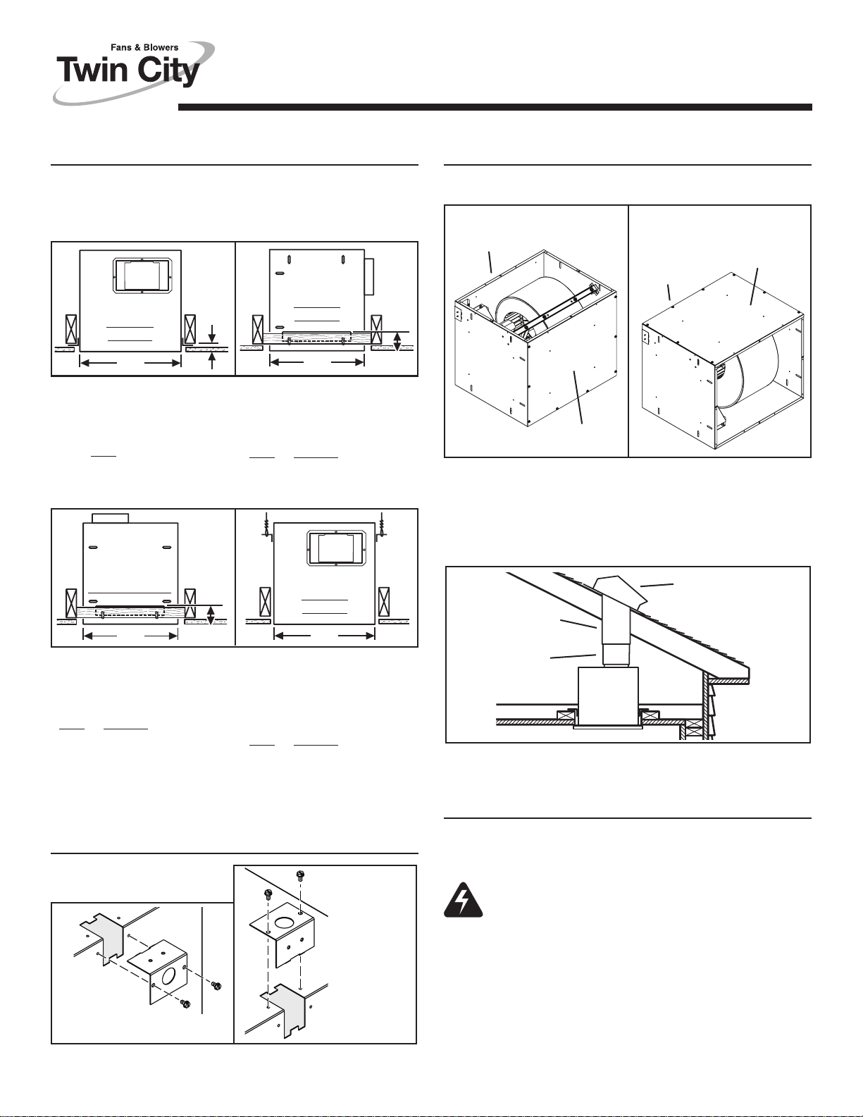
TYPICAL INSTALLATION
MOUNTING
ADDITIONAL
1½” FRAMING
Blower factory-shipped
in horizontal
discharge position.
GRILLE
(Install after
ceiling is
finished.)
(New Frame Construction)
ROUND DUCT*
Mounting brackets
factory-shipped in
position for ½”
ceiling material.
CEILING JOIST
(16” centers shown)
MOUNTING
SCREW
GRILLE
SCREW
TYPICAL INSTALLATION
WIRING
BLACK
TO
BLACK
GROUND TO
WIRING PLATE
WHITE
TO
WHITE
120 VAC LINE IN
Ventilator can be wired from outside of housing. Use UL
approved connectors to wire per local codes.
DUCTING
(Horizontal blower discharge)
TOP / BACK
OF HOUSING
WIRING
PLATE
Factory-shipped unit installed in new construction.
MOUNTING
CEILING JOIST
(16” centers
shown)
MOUNTING
BRACKETS
(Attached to
opposite sides
of housing &
upside-down,
so housing is
flush with
finished ceiling)
(Existing Frame Construction)
2 X 4 FRAMING
(wide side down)
ROUND DUCT*
FINISHED
MATERIAL
GRILLE
(Polymeric shown)
Factory-shipped unit installed in existing construction.
* T100 & T150 use 6” round duct.
T200, T250 & T300 use 8” round duct.
CEILING
GRILLE
SCREW
ROOF CAP
ROUND
DUCT*
WALL
ROUND
ELBOW*
CAP
Two ways to connect ductwork to a factory-shipped unit.
* T100 & T150 use 6” round duct.
T200, T250 & T300 use 8” round duct.
IMPORTANT:
Remove shipping tape from damper
Remove the shipping tape from the damper flap and make sure
that damper flap opens and closes freely inside the ductwork. Use
duct tape to make ductwork connections secure and air-tight.
Remove shipping ring from blower inlet
Remove the shipping ring from the blower inlet before operating
the ventilator.
Page 9

MODELS • T100 • T150
"
"
T200 • T250 • T300
Page 3
MOUNTING OPTIONS
¼-20 hex nuts secure mounting brackets to housing. Loosen and
re-tighten or remove and replace nuts as necessary for desired
mounting bracket position.
1
MAX.
12¼"
Mounting Brackets in
factory-shipped position.
(Outlet parallel to joists.)
(
New construction)
12¼"
Mounting Brackets mounted
to outlet sides of housing.
(Outlet perpendicular to joists.)
New construction)
(
1
/
8"
12¼"
Mounting Brackets flipped
over and mounted to outlet
sides of housing.
(Outlet parallel to joists.)
(
Existing construction)
12¼"
Mounting Brackets flipped
over to give approx. 1”
more clearance.
(Outlet parallel to joists.)
New construction)
(
1½"
to
2½"
1
2
1
2"
/
to
1
/
2"
DUCTING OPTIONS
BLOWER DISCHARGE POSITIONS
DUCT CONNECTOR
BLOWER
Blower and duct connector in
horizontal discharge position.
(Factory shipped)
DUCTING
ROUND
DUCT*
(Vertical blower discharge)
DUCT CONNECTOR
Change
blower &
duct
connector
positions for
vertical
discharge.
BLOWER
Blower and duct connecter in
vertical discharge position.
ROOF CAP
1
2
"
/
9
to
1
10
2
"
/
12¼"
Mounting Brackets mounted
Mounting Brackets flipped
to top sides of housing.
(Outlet parallel to joists.)
(
New or existing construction)
(
New or existing construction)
WIRING OPTIONS
WIRING PLATE
POSITION
HORIZONTAL POWER
CABLE CONNECTION
Wiring plate mounts to side or top of housing.
12¼"
over and mounted to top
of sides of housing.
(Outlet parallel to joists.)
VERTICAL
POWER
CABLE
CONNECTION
3
4
/
10
to
3
4
11
/
* T100 & T150 use 6” round duct.
T200, T250 & T300 use 8” round duct.
Typical ductwork connection to a ventilator
converted to vertical discharge.
USE AND CARE
Ventilator is designed for continuous operation. If desired, it may
be controlled using an on/off switch or a solid-state, variable speed
control. Follow wiring instructions packed with control, and adhere
to all local and state codes, and the National Electrical Code.
WARNING: To reduce the risk of electric shock,
disconnect from power supply before servicing.
To clean grille: Use appropriate vacuum attachment or remove
grille and clean with a soft cloth and mild soap or detergent. Dry
grille thoroughly before reinstalling.
To clean blower assembly: Remove grille, unplug blower from
housing, remove blower mounting nuts, and carefully remove blower
from housing. Use appropriate vacuum attachment or a soft cloth
and mild soap or detergent to clean blower discharge area and
wheel. DO NOT ALLOW WATER TO ENTER MOTOR. Make sure
blower assembly is completely dry before reinstalling.
Motor is permanently lubricated. Do not oil or disassemble motor.
Page 10
MODELS • T100 • T150
T200 • T250 • T300
Page 4
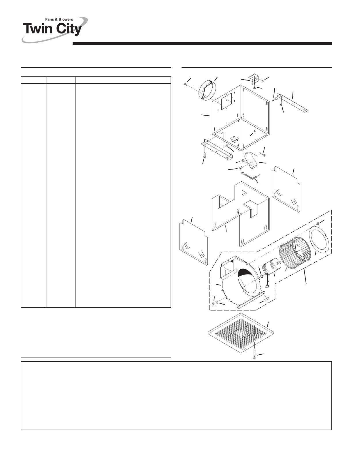
SERVICE PARTS
KEY NO. PART NO. DESCRIPTION
1 97014725 Housing Assembly (T100 & T150)
97014726 Housing Assembly (T200,
T250, & T300)
2 97014728 Mounting Bracket (2 req.)
3 97014760 Damper Assembly (6” dia.)
97014761 Damper Assembly (8” dia.)
4 99150415 Screw, 8-18 x ¼ (12 req.)*
5 98005513 Wire Box Cover
6 99400035 Strain Relief Bushing
7 98005512 Wiring Plate
8 99150471 Ground Screw, 10-32 x ½ (2 req.)
9 97014774 Scroll Assembly (T100 & T150)
97014775 Scroll Assembly (T200, T250, &
T300)
10 98009399 Inlet Ring
11 99110805 Blower Wheel
12 99080481 Motor (T100)
99080482 Motor (T150)
99080483 Motor (T200)
99080484 Motor (T250)
99080485 Motor (T300)
13 99260558 Lock Nut, 8-32 (4 req.)*
14 99250959 Washer (4 req.)*
15 99100491 Grommet (4 req.)
Blower Assembly, Complete
(Includes Key Nos. 4 & 9-15)
97014800 (T100)
97014801 (T150)
97014802 (T200)
97014803 (T250)
97014804 (T300)
16 99260477 Nut, ¼-20 (6 req.)*
17 97006039 Wire Harness
18 99500390 Wrapper Insulation
19 99500391 Side Insulation (2 req.)
20 99420466 Insulation Mounting Clip
21 99110807 Grille
22 99420470 Grille Nut (2 req.)
23 99150472 Grille Mounting Screw (2 req.)
24 99150591 Screw, 10-16 x 7/8 (4 req.)*
Order replacement parts by PART NO. - not by KEY NO.
* Standard hardware - may be purchased locally.
SERVICE PARTS
9
13
3
7
23
16
4
6
17
18
15
14
16
4
1
25
19
8
20
5
21
4
20
2
25
19
4
10
11
12
BLOWER
ASSEMBLY
WARRANTY
Seller warrants to the original purchaser that the goods sold hereunder shall be free from defects in workmanship and material under normal use and service (except in those cases where the materials
are supplied by the buyer) for a period of one year from the date of original installation or eighteen (18) months from the date of shipment, whichever occurs first. The liability of seller under this warranty
is limited to replacing, repairing, or issuing credit (at cost, F.O.B. factory and at seller’s discretion) for any part or part s which are returned by buyer during such period provided that:
a. seller is notified in writing within ten (10) days following discovery of such defects by buyer, or within ten (10) days afte r such defects should reasonably have been discovered, whichever is less;
b. the defective unit is returned to seller, transportation charges prepaid by buyer.
c. payment in full
d. seller’s examination of such unit shall disclose to its satisfaction that such defects have not been caused by misuse, neglect, improper installation, repair, alteration, act of God, or accident.
No warranty made hereunder shall extend to any seller product whose serial number is altered, effaced or removed. Seller makes no warranty, express or implied, with respect to motors, switches, controls,
or other components of seller’s product, where such components are warranted separately by their respective manufacturers. THIS WARRANTY IS EXPRESSLY IN LIEU OF ALL OTHER WARRANTIES,
EXPRESS OR IMPLIED, WHETHER STATUTORY OR OTHERWISE, INCLUDING ANY IMPLIED WARRANTY OF MERCHANTABILITY OR FITNESS FOR A PARTICULAR PURPOSE. In no event shall
seller be liable to buyer for indirect, incidental collateral
SHALL OPERATE TO RELEASE SELLER FROM ANY AND ALL LIABILITY OR OBLIGATION ARISING PURSUANT TO ANY WARRANTY, EXPRESS OR IMPLIED, WHETHER STATUTORY OR
OTHERWISE, INCLUDING ANY IMPLIED WARRANTY OR MERCHANTABILITY OR FITNESS FOR A PARTICULAR PURPOSE, MADE IN CONNECTION WITH ANY CONTRACT FORMED HEREUNDER. BUYER AGREES THAT SUCH FAILURE TO PAY SHALL CONSTITUTE A VOLUNTARY WAIVER OF ANY AND ALL SUCH WARRANTIES ARISING PURSUANT TO SUCH CONTACT.)
has been received by seller or said products; and
, or consequential damages of any kind. (BUYER’S FAILURE TO PAY THE FULL AMOUNT DUE WITHIN SIXTY (60) DAYS OF DATE OF INVOICE
TWIN CITY FAN & BLOWER, 5959 Trenton Lane, Minneapolis, MN 55442
Limitation of Warranties and Claims
24
99042948A
Page 11

CEILING / WALL-MOUNT
VENTILATORS • 120V
READ AND SAVE THESE INSTRUCTIONS
MODELS
T400 • T500 • T700
Page 1
Page 1
WARNING
TO REDUCE THE RISK OF FIRE, ELECTRIC SHOCK, OR INJURY TO PERSONS, OBSERVE THE FOLLOWING:
1. Use this unit only in the manner intended by the manufacturer. If
you have questions, contact the manufacturer at the address or
telephone number listed in the warranty.
2. Before servicing or cleaning unit, switch power off at service panel
and lock the service disconnecting means to prevent power from
being switched on accidentally. When the service disconnecting
means cannot be locked, securely fasten a prominent warning
device, such as a tag, to the service panel.
3. Installation work and electrical wiring must be done by a qualified person(s) in accordance with all applicable codes and standards, including fire-rated construction codes and standards.
4. Sufficient air is needed for proper combustion and exhausting of
gases through the flue (chimney) of fuel burning equipment to
prevent backdrafting. F ollow the heating equipment
manufacturer’s guideline and safety standards such as those
published by the National Fire Protection Association (NFPA),
and the American Socie
ditioning Engineers (ASHRAE), and the local code authorities.
5. When cutting or drilling into wall or ceiling, do not damage electrical wiring and other hidden utilities.
6. Ducted fans must always be vented to the outdoors.
7. To reduce the risk of fire, use only metal ductwork.
8. If this unit is to be installed over a tub or shower, it must be
marked as appropriate for the application and be connected to a
GFCI (Ground Fault Interrupter) - protected branch circuit.
9. Never place a switch where it can be reached from a tub or
shower.
10. This unit must be grounded.
ty for Heating, Refrigeration and Air Con-
TABLE OF CONTENTS
This manual is divided into sections as follows:
• “TYPICAL INSTALLATION”
This section shows a common installation in new and existing,
frame construction.
- Mounting (new construction)
- Mounting (existing construction)
- Wiring
- Ducting (horizontal blower discharge)
• “MOUNTING OPTIONS”
• “WIRING OPTIONS”
-Wiring Plate Position
• “DUCTING OPTIONS”
- Blower Discharge Positions
- Ducting (vertical blower discharge)
• “USE AND CARE”
• “SERVICE PARTS”
• “WARRANTY”
CAUTION
1. For general ventilating use only. Do not use to exhaust hazardous or explosive materials and vapors.
2. To avoid motor bearing damage and noisy and/or unbalanced
impellers, keep drywall spray, construction dust, etc. off power
unit.
3. Please read specification label on product for further information and requirements.
!
Installer: Leave this manual with
the homeowner.
Homeowner: Use and Care
information on page 3.
Page 12

MODELS
T400 • T500 • T700
Page 2
TYPICAL INSTALLATION
MOUNTING
4½” X 18½”
TO 10” ROUND
TRANSITION
Blower factory-shipped
in horizontal
discharge position.
GRILLE
Install after ceiling is
finished.
Factory-shipped unit installed in new construction.
(New Frame Construction)
10” ROUND DUCT
Mounting brackets
factory-shipped in
position for ½”
ceiling material.
MOUNTING
SCREW
GRILLE SCREW
CEILING
JOIST
(24” centers
shown)
TYPICAL INSTALLATION
WIRING
BLACK
TO
BLACK
GROUND TO
WIRING PLATE
WHITE
TO
WHITE
120 VAC LINE IN
Ventilator can be wired from outside of housing.
Use UL approved connectors to wire per local codes.
DUCTING
(Horizontal blower discharge)
ROOF CAP
TOP / BACK
OF HOUSING
WIRING
PLATE
MOUNTING
4½” X 18½”
TO 10” ROUND
TRANSITION
10” ROUND
DUCT
MOUNTING
BRACKETS
(Attached to
opposite sides
of housing &
upside-down,
so housing is
flush with
finished ceiling)
(Existing Frame Construction)
2 X 4 FRAMING
(wide side down)
GRILLE
Factory-shipped unit installed in existing construction.
CEILING JOIST
(24” centers
shown)
MOUNTING
SCREW
FINSHED
CEILING
MATERIAL
GRILLE
SCREW
4½” X 18½”
TO 10” ROUND
TRANSITION
ROUND
ELBOW
10”
10”
ROUND
DUCT
WALL
CAP
Two ways to connect ductwork to a factory-shipped unit.
NOTE: Make sure the shipping tape is removed from the damper
flap and that damper flap opens and closes freely inside the
ductwork. Use duct tape to make ductwork connections secure and
air-tight.
Page 13

MODELS
T400 • T500 • T700
Page 3
MOUNTING OPTIONS
¼-20 hex nuts secure mounting brackets to housing. Loosen and
re-tighten or remove and replace nuts as necessary for desired
mounting bracket position.
10
11
1½"
2½"
1
2
3
/
to
1
2"
/
to
1
2"
/
4
" to
3
4
"
/
1
/
1
MAX.
21½"
Mounting brackets in
factory-shipped position.
(Outlet parallel to joists.)
(
New construction)
12¼"
Mounting brackets mounted
to outlet sides of housing.
(Outlet perpendicular to joists.)
(
New construction)
1
/
9
2
" to
1
/
10
8
"
21½"
Mounting brackets flipped
over and mounted to outlet
sides of housing.
(Outlet parallel to joists.)
(
Existing construction)
21½"
Mounting brackets flipped
over to give approx. 1”
more clearance.
(Outlet parallel to joists.)
New construction)
(
2
"
DUCTING OPTIONS
BLOWER DISCHARGE POSITIONS
DUCT CONNECTOR
BLOWER
Blower and duct
connector in horizontal
discharge position
(factory shipped).
DUCTING
10”
ROUND
DUCT
(Vertical blower discharge)
Change
blower
& duct
connector
positions
vertical
for
discharge.
ROOF CAP
DUCT CONNECTOR
BLOWER
Blower and duct
connector in vertical
discharge position.
4½” X 18½”
TO 10” ROUND
TRANSITION
21½"
Mounting brackets mounted
to top sides of housing.
(Outlet parallel to joists.)
(
New or existing construction)
Mounting brackets flipped
over and mounted to top of
(
New or existing construction)
WIRING OPTIONS
WIRING PLATE
POSITION
HORIZONTAL POWER
CABLE CONNECTION
Wiring plate mounts to side or top of housing.
21½"
sides of housing.
(Outlet parallel to joists.)
VERTICAL
POWER
CABLE
CONNECTION
Typical ductwork connection to a ventilator
converted to vertical discharge.
USE AND CARE
Ventilator is designed for continuous operation. If desired, it may be
controlled using an on/off switch or a solid-state, variable speed
control. Follow wiring instructions packed with control, and adhere
to all local and state codes, and the National Electrical Code.
WARNING: To reduce the risk of electric shock,
disconnect from power supply before servicing.
To clean grille: Use appropriate vacuum attachment or remove
grille and clean with a soft cloth and mild soap or detergent. Dry
grille thoroughly before reinstalling.
To clean blower assembly: Remove grille, unplug blower from
housing, remove blower mounting nuts, and carefully remove blower
from housing. Use appropriate vacuum attachment or a soft cloth
and mild soap or detergent to clean blower discharge area and
wheel. DO NOT ALLOW WATER TO ENTER MOTOR. Make sure
blower assembly is completely dry before reinstalling.
Motor is permanently lubricated. Do not oil or disassemble motor.
Page 14
MODELS
T400 • T500 • T700
SERVICE PARTS SERVICE PARTS
KEY NO. PART NO. DESCRIPTION
1 97014744 Housing Assembly
2 97014728 Mounting Bracket (2 req.)
3 98009449 Duct Connector
4 97014822 Damper Flap Assembly (2 req.)
5 99150415 Screw, 8-18 x ¼ (18 req.)*
6 98005512 Wiring Plate
7 99150471 Ground Screw, 10-32 x ½ (2 req.)
8 98005513 Wire Box Cover
9 99400035 Strain Relief Bushing
10 97006039 Wire Harness
11 99500392 Wrapper Insulation
12 99500391 Side Insulation (2 req.)
13 99420466 Insulation Mounting Clip (6 req.)
14 99260477 Nut, ¼-20 (12 req.)*
15 97014745 Scroll Assembly (2 req.)
16 99110805 Blower Wheel (2 req.)
17 98009399 Inlet Ring (2 req.)
18 99080486 Motor (T400)
19 97014794 Motor Mounting Bracket
20 99100497 Rubber Isolator (4 req.)
21 99160380 Screw, 10-24 x 7/8 (4 req.)*
22 99250399 Washer (4 req.)*
23 99260306 Nut, Hex 10-24 (4 req.)*
24 99250254 Washer (4 req.)*
25 93260456 Nut, Hex Flange 3/8-16
26 98009461 Scroll Mounting Channel
--- ------------- Blower Assembly, Complete
27 98009463 Grille
28 99420470 Grille Nut (4 req.)
29 99150472 Grille Mounting Screw (4 req.)
30 99150591 Screw, 10-16 x 7/8 (4 req.)
Order replacement parts by PART NO. - not by KEY NO.
* Standard hardware - may be purchased locally.
99080487 Motor (T500)
99080488 Motor (T700)
(Includes Key Nos. 5 &
97014817 (T400)
97014819 (T500)
97014821 (T700)
14-26)
4
3
1
30
12
17
16
15
14
5
6
9
2
14
10
11
19
23
24
25
18
26
14
20
21
Page 4
5
7
5
8
22
2
13
28
12
14
5
17
16
15
BLOWER
ASSEMBLY
27
29
WARRANTY
Seller warrants to the original purchaser that the goods sold hereunder shall be free from defects in workmanship and material under normal use and service (except in those cases where the materials are supplied
by the buyer) for a period of one year from the date of original installation or eighteen (18) months from the date of shipment, whichever occurs first. The liability of seller under this warranty is limited to replacing, repairing,
or issuing credit (at cost, F.O.B. factory and at seller’s discretion) for any part or parts which are returned by buyer during such period provided that:
a. seller is notified in writing within ten (10) days following discovery of such defects by buyer, or within ten (10) days after such defects should reasonably have been discovered, whichever is less;
b. the defective unit is returned to seller, transportation charges prepaid by buyer.
c. payment in full has been received by seller or said products; and
d. seller’s examination of such unit shall disclose to its satisfaction that such defects have not been caused by misuse, neglect, improper installation, repair, alteration, act of God, or accident.
No warranty made hereunder shall extend to any seller product whose serial number is altered, effaced or removed. Seller makes no warranty, express or implied, with respect to motors, switches, controls, or other
components of seller’s product, where such components are warranted separately by their respective manufacturers. THIS WARRANTY IS
IMPLIED, WHETHER STATUTORY OR OTHERWISE, INCLUDING ANY IMPLIED WARRANTY OF MERCHANTABILITY OR FITNESS FOR A PARTICULAR PURPOSE. In no event shall seller be liable to buyer
for indirect, incidental collateral, or consequential damages of any kind. (BUYER’S FAILURE TO PAY THE FULL AMOUNT DUE WITHIN SIXTY (60) DAYS OF DATE OF INVOICE SHALL OPERATE TO RELEASE
SELLER FROM ANY AND ALL LIABILITY OR OBLIGATION ARISING PURSUANT TO ANY WARRANTY, EXPRESS OR IMPLIED, WHETHER STATUTORY OR OTHERWISE, INCLUDING ANY IMPLIED
WARRANTY OR MERCHANT
TO PAY SHALL CONSTITUTE A VOLUNTARY WAIVER OF ANY AND ALL SUCH WARRANTIES ARISING PURSUANT TO SUCH CONTACT.)
ABILITY OR FITNESS FOR A PARTICULAR PURPOSE, MADE IN CONNECTION WITH ANY CONTRACT FORMED HEREUNDER. BUYER AGREES THAT SUCH FAILURE
TWIN CITY FAN & BLOWER, 5959 Trenton Lane, Minneapolis, MN 55442
Limitation of Warranties and Claims
EXPRESSLY IN LIEU OF ALL OTHER WARRANTIES, EXPRESS OR
99042951A
Page 15

CEILING / WALL-MOUNT
VENTILATORS • 120V
READ AND SAVE THESE INSTRUCTIONS
MODELS • T900 • T1500
Page 1
WARNING
TO REDUCE THE RISK OF FIRE, ELECTRIC SHOCK, OR INJURY TO PERSONS, OBSERVE THE FOLLOWING:
1. Use this unit only in the manner intended by the manufacturer. If
you have questions, contact the manufacturer at the address or
telephone number listed in the warranty.
2. Before servicing or cleaning unit, switch power off at service panel
and lock the service disconnecting means to prevent power from
being switched on accidentally. When the service disconnecting
means cannot be locked, securely fasten a prominent warning
device, such as a tag, to the service panel.
3. Installation work and electrical wiring must be done by a qualified person(s) in accordance with all applicable codes and standards, including fire-rated construction codes and standards.
4. Sufficient air is needed for proper combustion and exhausting of
gases through the flue (chimney) of fuel burning equipment to
prevent backdrafting. F ollow the heating equipment
manufacturer’s guideline and safety standards such as those
published by the National Fire Protection Association (NFPA),
and the American Society for Heating, Refrigeration and Air Conditioning Engineers (ASHRAE), and the local code authorities.
5. When cutting or drilling into wall or ceiling, do not damage electrical wiring and other hidden utilities.
6. Ducted fans must always be vented to the outdoors.
7. To reduce the risk of fire, use only metal ductwork.
8. If
this unit is to be installed over a tub or shower, it must be
marked as appropriate for the application and be connected to a
GFCI (Ground Fault Interrupter) - protected branch circuit.
9. Never place a switch where it can be reached from a tub or
shower.
10. This unit must be grounded.
TABLE OF CONTENTS
This manual is divided into sections as follows:
• “TYPICAL INSTALLATION”
This section shows a common installation in new and existing,
frame construction.
- Mounting (new construction)
- Mounting (existing construction)
- Wiring
- Ducting (horizontal blower discharge)
• “MOUNTING OPTIONS”
• “WIRING OPTIONS”
-Wiring Plate Position
• “DUCTING OPTIONS”
- Blower Discharge Positions
- Ducting (vertical blower discharge)
• “USE AND CARE”
• “SERVICE PARTS”
• “WARRANTY”
CAUTION
1. For general ventilating use only. Do not use to exhaust hazardous or explosive materials and vapors.
2. To avoid motor bearing damage and noisy and/or unbalanced
impellers, keep drywall spray, construction dust, etc. off power
unit.
3. Please read specification label on product for further information and requirements.
!
Installer: Leave this manual with
the homeowner.
Homeowner: Use and Care
information on page 3.
Page 16

MODELS • T900 • T1500
Page 2
TYPICAL INSTALLATION
MOUNTING
GRILLE NUT
(Install into square
holes in housing)
Ventilator
factory-shipped
in horizontal
discharge
position.
GRILLE
SCREW
Factory-shipped unit installed in new construction.
(New Frame Construction)
12” ROUND DUCT
8” X 12” TO
12” ROUND
TRANSITION
(24” centers
MOUNTING
BRACKETS
factory-shipped
in position for
½” ceiling
material.
GRILLE
(Install after ceiling is finished.)
CEILING
JOIST
shown)
TYPICAL INSTALLATION
WIRING
BLACK
TO
BLACK
GROUND TO
WIRING PLATE
WHITE
TO
WHITE
120 VAC LINE IN
Ventilator can be wired from outside of housing.
Use UL approved connectors to wire per local codes.
DUCTING
(Horizontal blower discharge)
OF HOUSING
EDGE
WIRING
PLATE
MOUNTING
FINISHED
CEILING
MATERIAL
Ventilator factory-shipped
in horizontal
discharge position.
(Existing Frame Construction)
8” X 12” TO
12” ROUND
TRANSITION
12” ROUND
DUCT
MOUNTING BRACKETS
factory-shipped in position
for ½” ceiling material.
GRILLE
Factory-shipped unit installed in existing construction.
CEILING
JOIST
(24” centers
shown)
MOUNTING
SCREWS
GRILLE NUT
(Install into
square holes
in housing)
GRILLE
SCREW
ROOF CAP
8” X 12”
TO
12” ROUND
TRANSITION
12” ROUND
ELBOW
12”
ROUND
DUCT
WALL
CAP
Two ways to connect ductwork to a factory-shipped unit.
IMPORTANT:
Remove shipping tape from damper
Remove the shipping tape from the damper flap and make sure
that damper flap opens and closes freely inside the ductwork. Use
duct tape to make ductwork connections secure and air-tight.
Page 17
MODELS • T900 • T1500
Page 3
MOUNTING OPTIONS
¼-20 hex nuts secure mounting brackets to housing. Loosen and
re-tighten or remove and replace nuts as necessary for desired
mounting bracket position.
Factory-shipped
Horizontal
discharge
22"
1
MAX.
Mounting brackets in
factory-shipped position,
mounted directly to joists.
(Outlet parallel to joists.)
(
New construction)
Housing
Converted to
Vertical Discharge
18"
1½"
2½"
Mounting brackets flipped
over and mounted to
additional framing
(Outlet vertical.)
(
New or Existing construction)
Factory-shipped
1
/
8
"
Horizontal
discharge
18"
Mounting brackets flipped
over and mounted to
additional framing.
(Outlet perpendicular to joists.)
(
New or Existing construction)
to
Factory-shipped
Horizontal
discharge
22"
Mounting brackets flipped
over and mounted to
top of housing. Housing
secured with cables.
(Outlet parallel to joists.)
(
New or Existing construction)
1½"
to
2½"
DUCTING OPTIONS
BLOWER DISCHARGE POSITIONS
DUCT
CONNECTOR
(this side)
MOVABLE
PANEL
Ventilator shown in
horizontal discharge position
(factory shipped).
DUCTING
12” ROUND DUCT
8” X 12” TO
12” ROUND
TRANSITION
(Vertical blower discharge)
Typical ductwork connection to a ventilator
converted to vertical discharge.
DUCT
CONNECTOR
(this side)
Ventilator shown in
vertical discharge position
(change movable panel to
new location as shown).
ROOF CAP
MOVABLE
PANEL
(Change to this
location)
WIRING OPTIONS
WIRING PLATE
POSITION
HORIZONTAL POWER
CABLE CONNECTION
Wiring plate mounts to side or top of housing.
VERTICAL
POWER
CABLE
CONNECTION
USE AND CARE
Ventilator is designed for continuous operation. If desired, it may
be controlled using an on/off switch or a solid-state, variable speed
control. Follow wiring instructions packed with control, and adhere
to all local and state codes, and the National Electrical Code.
WARNING: To reduce the risk of electric shock,
disconnect from power supply before servicing.
To clean grille: Use appropriate vacuum attachment or remove
grille and clean with a soft cloth and mild soap or detergent. Dry
grille thoroughly before reinstalling.
To clean blower assembly: Remove grille, unplug blower from
housing, remove blower mounting nuts, and carefully remove blower
from housing. Use appropriate vacuum attachment or a soft cloth
and mild soap or detergent to clean blower discharge area and
wheel. DO NOT ALLOW WATER TO ENTER MOTOR. Make sure
blower assembly is completely dry before reinstalling.
Motor is permanently lubricated. Do not oil or disassemble motor.
Page 18

MODELS • T900 • T1500
SERVICE PARTS SERVICE PARTS
Page 4
KEY NO. PART NO. DESCRIPTION
1 97014853 Damper Flap
2 99150415 Screw, #8B x ¼* (10 req.)
3 98009520 Duct Connector
4 97014784 Housing Assembly
5 97014728 Mounting Bracket (2 req.)
6 99150591 Mounting Screw (4 req.)
7 97006142 Wiring Harness
8 99150471 Ground Screw, #10-32 x ½* (2 req.)
9 98005512 Wiring Adapter Plate
10 99420466 Insulation Mounting Clip (16 req.)
11 99420470 Grille Nut (4 req.)
12 98009518 Movable Housing Panel
13 93150487 Screw, #10-24 x .375* (8 req.)
14 98005513 Outlet Box Cover
15 99400035 Strain Relief Bushing
16 99500394 Insulation, Front
17 99500393 Insulation, Base
18 99500395 Insulation, Back
19 97014788 Motor Bracket
20 99260477 Whiz Nut, ¼-20* (11 req.)
21 99200202 Screw, ¼-20 x ½* (5 req.)
22 97014785 Blower Scroll
23 99080490 Motor (T900)
24 93260447 Nut, Hex Flange 5/16-18* (5 req.)
25 98009516 Support Bracket
26 99680019 Wheel Clamp
27 99020274 Blower
28 98009514 Inlet Ring
29 99150417 Screw, #8-18 x ¼* (5 req.)
30 98009513 Scroll Support Channel
+ 97014848 Blower Assembly Complete (T900)
+ 97014849 Blower Assembly Complete (T1500)
31 98009522 Grille
32 99150472 Grille Screw (4 req.)
Order replacement parts by PART NO. - not by KEY NO.
* Standard hardware - may be purchased locally.
+ Not shown assembled.
99080491 Motor (T1500)
Wheel (includes Key No. 26)
(Includes Key Nos. 19 thru 30)
(Includes Key Nos. 19 thru 30)
1
7
2
16
20
19
23
24 21
6
21
8
9
17
22
2
3
4
5
20
11
15
10
13
12
14
18
27
28
26
29
30
25
20
BLOWER
ASSEMBLY
32
31
WARRANTY
Seller warrants to the original purchaser that the goods sold hereunder shall be free from defects in workmanship and material under normal use and service (except in those cases where the materials
are supplied by the buyer) for a period of one year from the date of original installation or eighteen (18) months from the date of shipment, whichever occurs first. The liability of seller under this warranty
is limited to replacing, repairing, or issuing credit (at cost, F.O.B. factory and at seller’s discretion) for any part or part s which are returned by buyer during such period provided that:
a. seller is notified in writing within ten (10) days following discovery of such defects by buyer, or within ten (10) days afte r such defects should reasonably have been discovered, whichever is less;
b. the defective unit is returned to seller, transportation charges prepaid by buyer.
c. payment in full ha
d. seller’s examination of such unit shall disclose to its satisfaction that such defects have not been caused by misuse, neglect, improper installation, repair, alteration, act of God, or accident.
No warranty made hereunder shall extend to any seller product whose serial number is altered, effaced or removed. Seller makes no warranty, express or implied, with respect to motors, switches, controls,
or other components of seller’s product, where such components are warranted separately by their respective manufacturers. THIS WARRANTY IS EXPRESSLY IN LIEU OF ALL OTHER WARRANTIES,
EXPRESS OR IMPLIED, WHETHER STATUTORY OR OTHERWISE, INCLUDING ANY IMPLIED WARRANTY OF MERCHANTABILITY OR FITNESS FOR A PARTICULAR PURPOSE. In no event shall
seller be liable to buyer for indirect, incidental collateral, or
SHALL OPERATE TO RELEASE SELLER FROM ANY AND ALL LIABILITY OR OBLIGATION ARISING PURSUANT TO ANY WARRANTY, EXPRESS OR IMPLIED, WHETHER STATUTORY OR
OTHERWISE, INCLUDING ANY IMPLIED WARRANTY OR MERCHANTABILITY OR FITNESS FOR A PARTICULAR PURPOSE, MADE IN CONNECTION WITH ANY CONTRACT FORMED HEREUNDER. BUYER AGREES THAT SUCH FAILURE TO PAY SHALL CONSTITUTE A VOLUNTARY WAIVER OF ANY AND ALL SUCH WARRANTIES ARISING PURSUANT TO SUCH CONTACT.)
s been received by seller or said products; and
consequential damages of any kind. (BUYER’S FAILURE TO PAY THE FULL AMOUNT DUE WITHIN SIXTY (60) DAYS OF DATE OF INVOICE
TWIN CITY FAN & BLOWER, 5959 Trenton Lane, Minneapolis, MN 55442
Limitation of Warranties and Claims
99042954B
 Loading...