

Page 1
BACKWARD INCLINED HINGED
RESTAURANT EXHAUST FAN
INSTALLATION, OPERATION & MAINTENANCE MANUAL
IM-610
August 2014
Twin City Fan & Blower Catalog 610 provides additional information on this equipment, fan performance,
optional accessories and construction features. This
catalog can be found at www.tcf.com or by contacting
your local Twin City Fan & Blower sales representative.
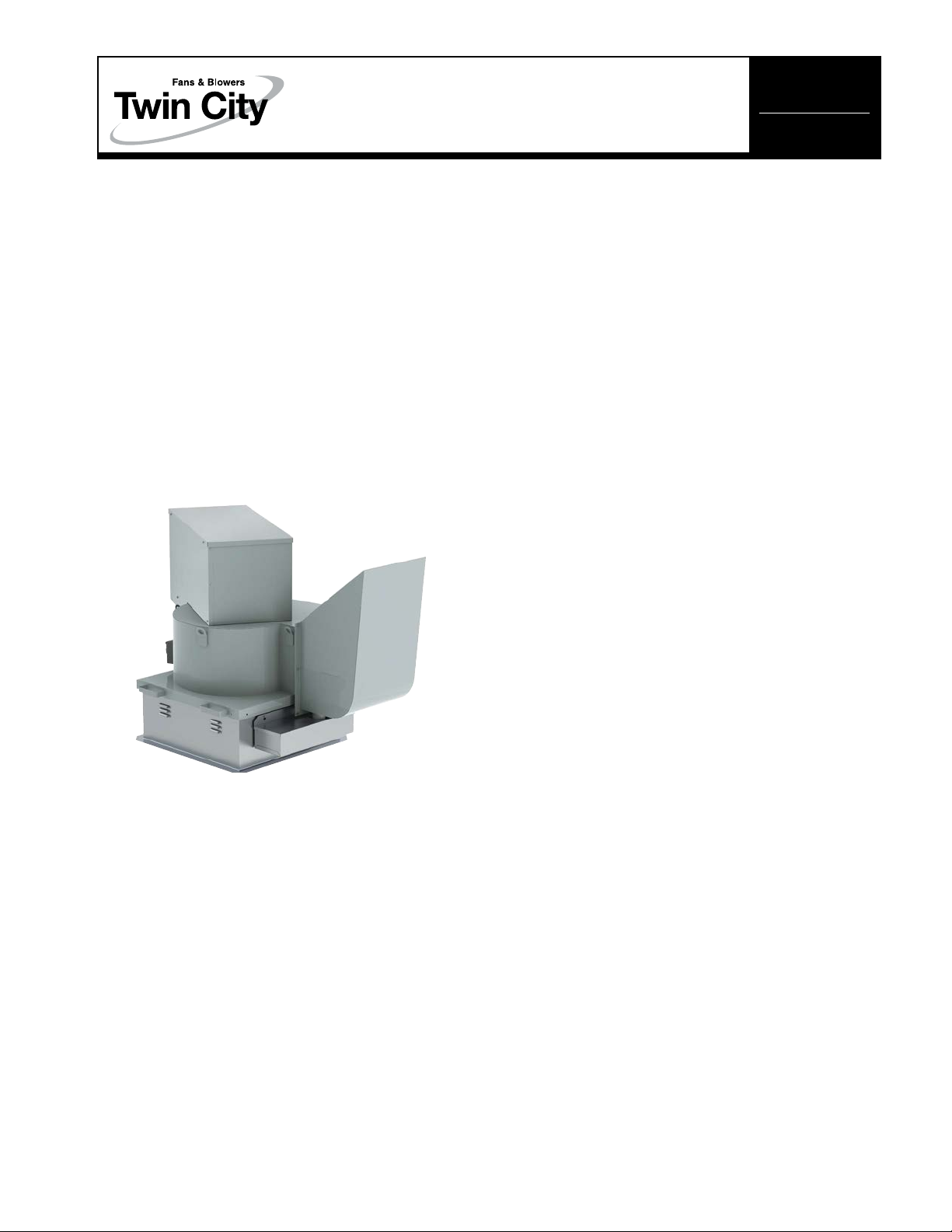
HEAVY DUTY RESTAURANT EXHAUST
Belt Drive Model: BHRE
Type: Centrifugal Roof Exhaust
CFM to 9,043 (15,365 m³/hr)
Static Pressure to 5.00 in. w.g. (1,245 Pa)
Maximum Continuous Operating Temperature:
400°F (204.4°C)
Available in nine sizes: 105 - 245, nominal wheel
diameter 10.5 to 24.5 inches (267-622 mm)
General Installation
CAUTION: Sheet metal parts, screws, clips and similar
items inherently have sharp edges, and it is necessary
that the installer and service personnel exercise caution.
The installation of this equipment shall be in accordance
with the regulations of authorities having jurisdiction and
all applicable codes.
This equipment is to be installed by an experienced
installation company and fully trained personnel. The
mechanical installation of the exhaust ventilator consists
of making final connections between the unit and building services.
CAUTION: Disconnect power and lock out power source
before installing or servicing. Failure to disconnect power
can result in electric shock, fire or serious injury.
1. Do not operate the fan beyond the maximum cataloged RPM. The current should be verified any time
the RPM is adjusted to ensure it is below the
nameplate amperage value.
2. Verify the equipment is compatible with the power source.
3. Allow motor to cool down before servicing to avoid
injury.
Receiving
When the equipment is received, all items should be
carefully checked against the bill of lading to ensure all
items have been received. Inspect each package for
shipping damage before accepting delivery.
If any damage occurred, notify the carrier, who will make
proper notation on the delivery receipt acknowledging
the damage. Damages should be noted on all copies of
the bill of lading and have all copies countersigned by
the delivering carrier. A Carrier Inspection Report should
be filled out and forwarded to the Traffic Department.
If units are damaged in transit, it is the responsibility of
the receiver to make all claims against the carrier. Twin
City Fan is not responsible for damages incurred during
shipment or after acceptance.
Short Term Storage
If fan installation is to be delayed, store the unit in a
protected area, preferably indoors. Protect fan bearings
and motor from moisture and vibration.
Long Term Storage
Prior to storage, grease fan bearings and motor bearings
per manufacturer's specifications. Note, motors which
contain ball bearings are permanently lubricated as built.
No additional lubrication is required. On belt drive units,
belts should be removed or at least the belt tension
reduced to prevent a sag/set from forming in the fan
shaft and belts. Rotate wheel and shaft monthly and
leave in a different position. When unit is to be removed
from storage and activated, check for corrosion and
damage. All bearing grease should be purged and
replaced with fresh grease.
Unpacking
Verify that all required parts and proper quantities have
been received for each item. Report shortages or missing items to your local representative to arrange for
replacement parts.
Sometimes it is not possible for all items to ship together due to availability of carriers and truck space.
Verification of shipments must be limited to only items
on the bill of lading.
©2012 Twin City Fan Companies, Ltd.
Page 2
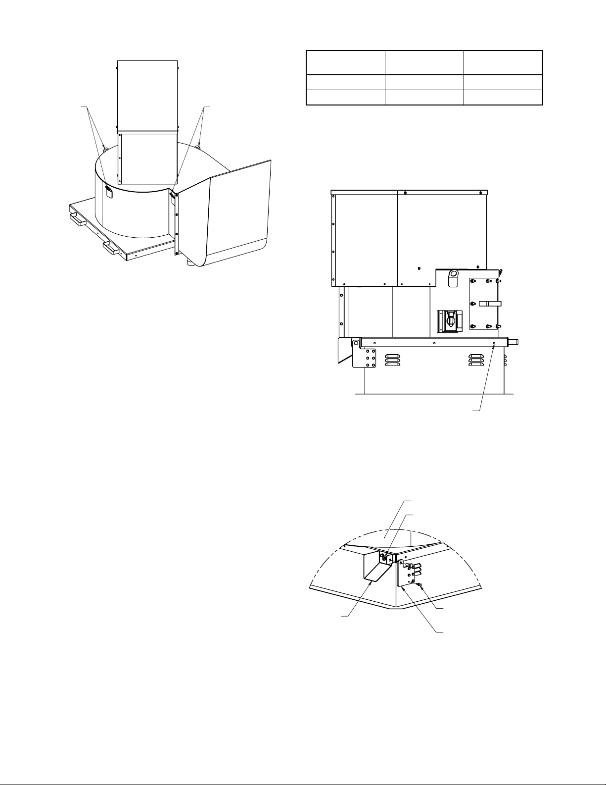
Fan
Lifting Lug
Figure 1.
Table 1. Fan Mounting to Roof Curb
Lifting Lug
Handling
Lift fan using all lift points. Use spreader bars to ensure
straps do not come in contact with unit. See Figure 1.
BHRE Size
Fasteners per
Side
105 2 8
122 - 245 3 12
Figure 2.
Total
Fasteners
Installation
Refer to Table 2 for appropriate size roof opening.
Follow curb manufacturer's recommended installation.
1. For lifting locations, see Fig. 1.
2. Position the fan with its wiring conduit in line with
the wiring or external disconnect, towards the power
supply. The location and placement of any supply
fans should be considered.
3. Center fan on roof curb, allow 3/4" (19 mm) space
all around.
4. Attach hinge bracket to fan with 1/2" cap screw and
nut. Adjust curb stop (bolted to fan) so hinge is
flush with roof curb.
5. Rotate hinge bracket such that mounting holes are
vertical and fasten curb hinge with hardware pack
(p/n HWPACK-1) according to Fig. 3.
6. Screw fan to the roof curb using #12-14 dril-flex or
equal 3" (76 mm) from each corner and one fastener centered. Add additional fasteners equally
spaced to satisfy. See Figure 2 and Table 1.
7. Verify the power is de-energized. Run wires to the
disconnect switch. Leave some slack in the wire in
the motor compartment so the motor and wheel
assembly can be lifted for inspection and cleaning.
8. Verify power source is compatible with the fan.
Make connection to the disconnect switch.
9. Check tightness of all fasteners.
10. Verify wheel is centered and spins freely.
11. Restaurant fan installation must be in compliance
with local codes and National Fire Protection
Association's standard NFPA 96.
#12-14 Dril-Flex self drilling
Figure 3.
Nut, 1/2-13
Curb Stop
All hardware found in package HWPACK-1
screw or equal
1/4-11 x .75 Dril-ex screw or equal
6 Locations
Hinge Bracket
(Both Sides)
2
Twin City IM-610
Page 3
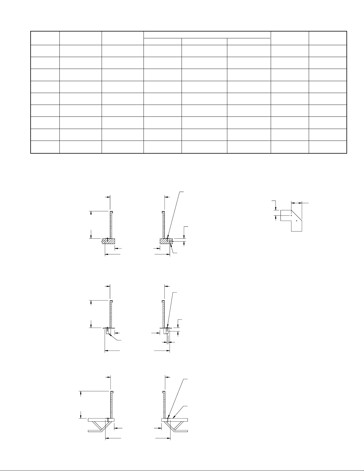
Table 2. Roof Curb Mounting to Building Structure
Concrete Anchoring Instructions for Roof Curbs
BHRE Size Curb Cab Roof Curb
105
122
135
150
165
182
200
222
245
20 x 20
(508 x 508)
23 x 23
(584 x 584)
25 x 25
(635 x 635)
27 1/2 x 27 1/2
(698 x 698)
29 x 29
(737 x 737)
31 1/2 x 31 1/2
(800 x 800)
34 x 34
(864 x 864)
38 x 38
(965 x 965)
41 1/2 x 41 1/2
(1054 x 1054)
18 1/2 x 18 1/2
(470 x 470)
21 1/2 x 21 1/2
(546 x 546)
23 1/2 x 23 1/2
(597 x 597)
26 x 26
(660 x 660)
27 1/2 x 27 1/2
(698 x 698)
30 x 30
(762 x 762)
32 1/2 x 32 1/2
(825 x 825)
36 1/2 x 36 1/2
(927 x 927)
40 x 40
(1016 x 1016)
Figure 4.
Outside of Roof Curb
Curb Height
8" - 18"
(203 - 457 mm)
1 1/2" (38 mm)
less than Fan Curb
[3/4" (19 mm) per side]
Minimum Fasteners
Steel Anchoring Concrete Anchoring Timber Anchoring
3 3 3
3 3 3
3 3 3
3 3 3
3 3 3
3 3 4
3 3 4
3 4 5
4 4 5
1/4" Dia. S.S. Hilti Kwik bolt expansion
anchors or equal.
4-1/2" (114 mm) min. spacing.
Located at each corner as shown.
Each side at center of unit.
Add additional fasteners to satisfy.
1.00
2" (51 mm) Min. Embedment
Outside
Flange
22 1/2 x 22 1/2
(571 x 571)
25 1/2 x 25 1/2
(648 x 648)
27 1/2 x 27 1/2
(698 x 698)
30 x 30 (762 x
762)
31 1/2 x 31 1/2
(800 x 800)
34 x 34 (864 x
864)
36 1/2 x 36 1/2
(927 x 927)
40 1/2 x 40 1/2
(1029 x 1029)
44 x 44 (1118 x
1118)
Corner Detail Of
All Structures - Typ
Roof
Opening
13 1/2 x 13 1/2
(343 x 343)
16 1/2 x 16 1/2
(419 x 419)
18 1/2 x 18 1/2
(470 x 470)
21 x 21
(533 x 533)
22 1/2 x 22 1/2
(571 x 571)
25 x 25
(635 x 635)
27 1/2 x 27 1/2
(698 x 698)
31 1/2 x 31 1/2
(800 x 800)
35 x 35
(889 x 889)
2.00
Curb Height
8" - 18"
(203 - 457 mm)
Curb Height
8" - 18"
(203 - 457 mm)
Roof Opening
Outside Flange
2000 PSI Min. Concrete Strength
Wood Anchoring Instructions for Roof Curbs
Outside of Roof Curb
1 1/2" (38 mm)
less than Fan Curb
[3/4" (19 mm) per side]
#10 Zinc plated wood screw or equal.
Located at each corner as shown.
Each side at center of unit.
3/4" (19 mm) min. spacing, 14-1/2" (368 mm) max. spacing.
Add additional fasteners to satisfy.
1-1/2" (38 mm) Min. Embedment
Roof Opening
Wood Buck
Min. S.G. = .55
Center fasteners
Outside Flange
Steel Anchoring Instructions for Roof Curbs
Outside of Roof Curb
1 1/2" (38 mm)
less than Fan Curb
[3/4" (19 mm) per side]
#12-14 Dril-ex self drilling screw or equal.
Located at each corner as shown.
Each side at center of unit.
3/4" (19 mm) min. spacing, 14-1/2" (368 mm) max. spacing.
Add additional fasteners to satisfy.
Min. 12 ga. or 1/8" (3 mm) thick steel member
Twin City IM-610
Roof Opening
Outside Flange
Fig. 3
3
Page 4
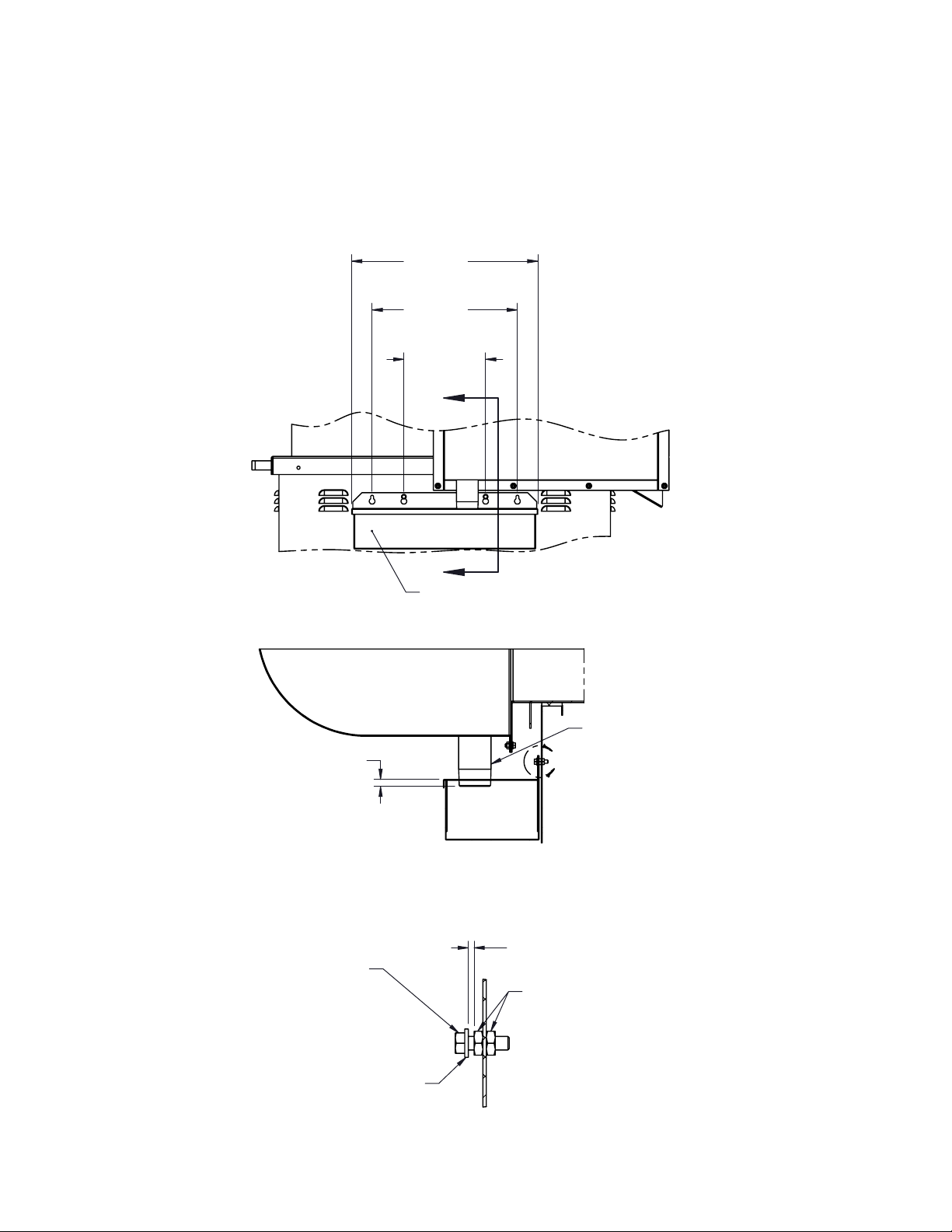
Grease Box Installation
1. Position Grease Box under the 2" NPT pipe with
approximately 1/2 - 3/4 in. (13-19 mm) overlap using
the inside or outside hole patterns.
2. Mark mounting hole locations on curb cap.
3. Drill two 5/16 in. (8 mm) diameter holes in marked
location.
4. Install 1/4 in. (6 mm) hardware to detail shown.
Figure 5.
20.48
(520 mm)
16.00
(406 mm)
9.00
(229 mm)
A
A
Grease Pad
(Inside box)
.50 - .75
(13 - 19 mm)
Cap Screw
1/4-20 x 3/4
Flat Washer, 1/4
Drain Pipe
B
SECTION A-A
.13
(3 mm)
Hex Nut, 1/4-20
DETAIL B
4
Twin City IM-610
Page 5

Table 3.
BHRE
Size
105 25.74 11.57 21.14 11.21 20.00 17.69 12.05 26.90 1.00 2 173
122 26.87 13.24 24.44 13.02 23.00 20.13 12.12 29.29 1.00 2 193
135 28.93 14.43 26.76 14.34 25.00 22.11 14.10 32.61 1.00 3 251
150 30.05 15.86 29.58 15.90 27.50 24.36 14.35 34.72 1.00 3 267
165 31.30 17.28 31.85 17.43 29.00 26.67 14.74 36.17 1.00 5 294
182 32.68 18.94 35.08 19.40 31.50 29.38 14.75 38.11 1.19 5 348
200 34.08 20.62 38.14 21.21 34.00 32.09 15.28 40.38 1.19 5 380
222 35.77 22.76 42.52 23.59 38.00 35.45 16.04 43.98 1.44 5 446
245 38.64 24.90 46.64 25.96 41.50 38.87 17.84 50.09 1.44 7.5 573
A B C D E F G H
Dimensions
Bearing
Size
Max
HP
Figure 6.
D
H
Approx.
Weight
(lbs)
A
MAX
2.00
G
E SQ.
INSIDE
C
B
F
2" NPT DRAIN
Twin City IM-610
5
Page 6

Electrical Connection
Standard Fan
1. Connect supply wiring to the disconnect switch (nonfused standard).
2. The motor is factory set at the voltage marked on the
fan nameplate. Check the line voltage with the nameplate voltage.
3. The main power wiring should be sized for the ampacity shown on the dataplate. Size wires in accordance
with the ampacity tables in Article 310 of the National
Electrical Code. If long wires are required, it may be
necessary to increase wire size to prevent excessive
voltage drop. Wires should be sized for a maximum
of 3% voltage drop.
CAUTION: Use copper conductors only.
any two of the three line leads. If the unit is checked with
temporary wiring, it should be rechecked when permanently installed. Motor burn out or tripped overload protection devices are usually the result of wrong rotation.
6. Electrical Input Check: Perform check of fan ampere
draw and verify that motor nameplate amps are not
exceeded. Take into account the service factor of the
motor if it is above 1.0 S.F.
7. Fan RPM should be checked and verified with a
tachometer.
CAUTION: Protect wiring from sharp edges. Leave some
slack in the line to prevent damage.
4. Disconnect switches are not fused. The power leads
must be protected at the point of distribution in accordance with the fan dataplate.
5. All units must be electrically grounded in accordance
with local codes or, in the absence of local codes,
with the latest edition of the National Electrical Code
(ANSI/NFPA 70). A ground lug is provided as standard
in the unit terminal box. Size grounding conductor in
accordance with Table 250-95 of the National Electrical
Code. DO NOT use the ground lug for connecting a
neutral conductor.
6. Supply voltage to the power ventilator should not vary
by more than 10% of the value indicated on the unit
dataplate. Phase unbalance must not exceed 2%.
Check, Test & Start Procedures
Warning: Electric shock hazard. Could cause severe
injury or death. Failure to bond the frame of this equipment to the building electrical ground by use of the
grounding terminal provided or other acceptable means
may result in electrical shock. Disconnect electric power
before servicing equipment. Service to be performed only
by qualified personnel.
Before Start-up: Disconnect power before servicing unit
Figure 7.
.44 Overlap,
Figure 8.
.13
Gap, Swingout Fan
.00
6
1. Check all fasteners and setscrews for tightness.
Note: The wheel position is set at the factory and the fan
was balanced and vibration tested prior to shipment.
Movement may have occurred during transport and realignment may be necessary.
2. Check that the wheel is centered and free to rotate.
Centering can be changed by loosening isolator
mounts and repositioning the drive frame.
3. For optimum fan performance make sure that the
wheel to inlet venturi gap or overlap is maintained per
Figure 7. Height can be adjusted by loosening set
screws on the wheel and reposition on the fan shaft,
per the table.
4. Verify that the power supply matches the voltage on
the fan data plate and is within the 10% utilization
rate.
5. Apply power to unit and check rotation of wheel with
the directional arrow on the unit. All fans are clockwise, as viewed from drive side, per Figure 8.
Warning: Rotation is critical. If allowed to operate in the
wrong direction, the motor will overload and burn out. For
three-phase units, rotation can be changed by switching
View from drive side
Twin City IM-610
Page 7

Inspection
Inspection of the fan should be completed at the first
30 minutes, 8 hour and 24 hour intervals of satisfactory operation.
30 Minute Interval
Inspect tightness of all hardware, setscrews and motor
mounting bolts. Adjust and tighten as necessary.
8 Hour Interval
Inspect belt alignment and tension. See Belt Adjustment
and tension as necessary
24 Hour Interval
Inspect belt tension, adjust as necessary.
Maintenance
A maintenance program should be established to maintain the reliability and performance of the fan. The
frequency of inspection depends on the location and
operating conditions of the fan.
Maintenance is to be performed only by qualified personnel who are familiar with local codes and regulations and experienced with this type of equipment.
Routine maintenance should cover the following:
a. Tighten all setscrews and hardware.
b. Check belt tension and sheaves for wear.
c. Lubricate fan bearings (see Table 4 for recom-
mended interval and Table 5 for grease types.
d. Cleaning of unit, wheel and grease box.
1. Before performing any maintenance on the fan, be
sure power is turned off and locked in the off
position at the service entrance.
2. Ventilators should be carefully checked at least
once a year. For critical or rugged applications, a
routine check every two or three months is suggested.
3. Always follow the bearing manufacturer's recom-
mended lubrication schedule. If not available, below
is a general guideline:
Table 4.
Bearing Greasing Intervals
Fan RPM Interval (months)
Up to 500 6
500 - 1,000 6
1,000 - 1,500 5
1,500 - 2,000 3
2,000 - 2,500 3
2,500 - 3,000 2
Divide the listed interval by 2 for vertical shaft applications or for 24 hour operation.
Relubricate while running, if safety permits, until some
purging occurs at seals. Adjust lubrication frequency
depending on condition of purged grease. Hours of
operation, temperature and surrounding conditions will
affect the relubrication frequency required.
4. All motors supplied with Twin City Fan & Blower
ventilators carry a one year limited warranty from
date of shipment. For repairs within the warranty
period, the motor must be taken to the motor man-
ufacturer's authorized service dealer. Contact your
TCF representative for additional warranty details.
5. A periodic motor check should consist of removing
the belt, then spinning the motor shaft with the
power off to be sure the motor turns freely and
the bearings run smoothly.
6. When removing or installing a belt, do not force
the belt over the sheave. Loosen the motor mount
so that the belt can be easily slipped over the
sheave. See Belt Adjustment, on page 8.
7. The belt should be removed and carefully checked
for glazing, cracks, ply separation or irregular wear.
A small irregularity in the contact surface of the
belt will result in noisy operation. If any defects are
apparent, the belt should be replaced.
8. Check sheaves for chipping, dents or rough surfaces which could damage the belt. Always replace
sheaves with identical size and type.
9. If the unit is left idle for an extended period, the
belts should be removed and stored in a cool, dry
place to avoid premature belt failure.
10. Check sheave setscrews to ensure tightness.
Proper keys must be in keyways.
11. Check for proper belt alignment. See Figure 10.
Improper alignment leads to excessive belt wear,
vibration, noise and power loss.
12. For two-groove drives, matched belts must be
used.
13. When replacing belts, use the same type & size as
supplied on the unit.
14. The standard pillow block bearings on belt driven
ventilators are factory lubricated and are provided
with external grease fittings. Lubrication bi-annually
is recommended, or more frequently if needed. (see
Table 5). It is recommended to add fresh grease
at start-up, but do not over-grease. Use only 1 or
2 shots of a recommended lubricant with a hand
gun in most cases (see Table 5). Maximum hand
gun rating of 40 psi. Rotate bearings during lubrication where good safety practice permits.
Caution: Greases of different soap bases (lithium,
sodium, etc.) may not be compatible when
mixed. Prevent such intermixing by completely purging the bearing of old greases.
Table 5.
Grease Manufacturers
Manufacturer Grease (NLGI #2)
Shell Gadus S2 V100 2
Exxon/Mobil Ronex MP
15. The most frequent causes of bearing failure are not
greasing often enough, using an excessive quantity
of grease or using incompatible greases. Excessive
vibration, especially if the bearing isn't rotating, will
also cause bearings to fail. Bearings must also be
protected from water and moisture to avoid internal
corrosion.
16. During the first few months of operation, it is recommended to periodically check the bearing setscrews to ensure tightness.
17. Wheels require attention when moving dirty or
grease laden air. Regular cleaning is required to
avoid imbalance caused by accumulation of grease
or dust.
18. All fasteners should be checked for tightness during each maintenance.
Twin City IM-610
7
Page 8

Motor Lubrication:
Fasteners
(Both Sides)
C
Lid
Standard Fan
(Both Sides)
Motor Cover
Motors which contain ball bearings are permanently lubricated from the factory. No additional maintenance is
required. Motors supplied with grease fittings should be
lubricated according to the manufacturer's recommendation.
Figure 9.
Access for Drive Inspectionk, Fig 9:
1. For inspection and belt tightening, remove motor
cover lid.
2. For unrestricted access to motor and drives, remove
motor cover.
Belt Adjustment, Detail C
1. Loosen screws (A) on motor plate; do not remove.
2. Turn jacking bolts (B) equally to proper belt tension.
(Ref Fig. 11).
3. Tighten screws (A).
Motor
Cover
Fasteners
(Both Sides)
Lid
V-Belts
V-belts are oil, heat and static resistant type and oversized for continuous duty.
The condition and the amount of belt deflection should
be checked prior to start-up. Do not over-tension as
bearing damage may occur. Recommended belt tension
C
is 1/64" multiplied by the center distance of sheaves (in
inches). (See Figure 11.)
Extreme care must be exercised when adjusting V-belts
as not to mis-align sheaves. Any misalignment will cause
a reduction in belt life and will increase the likelihood of
noise & vibration.
Figure 10.
Standard Fan
Fasteners
Figure 11.
Deection = 1/64 x Distance
Swingout Fan
A
B
Distance
(inches)
DETAIL C
8
Twin City IM-610
Page 9

Access for Cleaning:
Curb Stops
Remove Wingnuts
(Qty 1) Sizes 105-150
(Qty 2) Sizes 165-245
All models - Hinge fan open or remove outlet scoop held
on by screw/nut. See Fig. 12. It is recommended to use
two people to open the fan.
Swingout - Remove wingnut(s). Lift handle and rotate prop
rod onto stud. Secure with wingnut. See Fig. 13.
Figure 12. Hinged Fan
Handle
Screw
Hex Nut
Figure 13. Swingout Fan
Handle
Prop Rod
Stud/Wingnut
Twin City IM-610
9
Page 10

Lid
Curb Hinge
Motor
Cover
Gasket
Prop Rod
Gasket
(All models)
Swingout Fan
Roof Curb
Outlet
Scoop
Fan
Sheave
Bearing
Plate
Disconnect
Switch
Inlet Funnel
Wheel
Grease
Box
Motor
Cover
Prop
Rod
Retaining
Cable
Gasket
(All Models)
Parts List
Gasket
Motor
Cover
Prop
Rod
Retaining
Cable
Gasket
(All Models)
Gasket
Motor
Cover
Parts List
Fan Sheave
Bearing Plate
Motor
Sheave
Motor
Mounting Rail
Disconnect
Switch
Standard Fan
Wheel
Inlet Funnel
Roof Curb
(Optional)
Outlet
Scoop
Grease Box
(Optional)
Swingout Fan
Motor
Cover
Gasket
Prop Rod
Gasket
(All models)
10
Parts List
Refer to the TCF nameplate for model number and serial number to assist in ordering the correct replacement parts.
Be sure the unit is locked out/tagged out before repairing.
Twin City IM-610
Page 11

Table 6.
Symptom Cause Corrective Action
Fan does not operate
Too little air
Too much air
Excessive Noise or
Vibration
Excessive Horsepower
Motor Overloads/
Overheats
Electrical Supply
Drive
Motor
Wheel rotating in wrong direction Check wheel rotation, see Fig. 8, P.6
System resistance too high
Fan speed lower than design Tighten belt; close variable speed sheave.
Dampers closed Inspect and repair.
Improper wheel alignment
Excessive dirt/grease on wheel Clean wheel.
Fan inlet/outlet is restricted
Filters (if applicable) are dirty or clogged Clean or replace filters.
System resistance lower than expected
Fan speed higher than design Adjust fan speed.
Wheel hitting inlet
Loose sheave or wheel Align and tighten.
Wheel out of balance Clean wheel; check wheel balance.
Bearings
V-belts
Fan not properly anchored Secure fan base, see Table 2, P. 3
Loose components Tighten loose hardware.
Fan Check wheel rotation; reduce fan speed.
System resistance too high
Motor improperly wired
Incorrect wheel rotation Change wiring leads to correct rotation.
Undersized motor
Fan rpm too high
Over/Under line voltage Contact power company.
Fan
Check disconnect switch, fuses/breakers.
Check for correct supply voltage.
Check for broken belts. Tighten loose belts,
see Belt Adjustment
Check overload protection on motor. Verify
correct motor horsepower.
Check system backdraft dampers, ductwork
and filters.
Center wheel on inlet, check wheel gap/over
lap against Fig. 7, P.6
Remove obstruction, check for damage or
unbalance.
Reduce fan speed to reach required operat
ing point.
Center wheel on inlet, check wheel gap/over
lap against Fig. 7, P. 6
Lubricate bearings, replace defective bear
ings; tighten setscrew or bearing bolt, align
bearings.
Mismatched belts, replace with matched
belts; Adjust belt tension, replace worn belt.
Check dampers; re-size ductwork; check fan
inlet conditions; check filter.
Check motor wiring against wiring diagram
on motor nameplate.
Check motor ratings against cataloged performance.
Check fan rpm; open variable pitch sheave
on motor.
Check for bent shaft; check for proper belt
tension; check for damaged bearings.
-
-
-
-
It is recommended that the users and installers of this equipment familiarize themselves with AMCA Publication
#201, "Fans and Systems" and publication # 202 "Troubleshooting" which are published by the Air Movement
and Control Association (AMCA), 30 West University Drive, Arlington Heights, Illinois 60004. www.amca.org
Twin City IM-610
11
Page 12

LIMITATIONS OF WARRANTIES and CLAIMS
Seller warrants to the original purchaser that the goods
sold hereunder shall be free from defects in workmanship and material under normal use and service (except
in those cases where the materials are supplied by the
buyer) for a period of one year from the date of original
installation or eighteen (18) months from the date of
shipment, whichever occurs first. The liability of seller
under this warranty is limited to replacing, repairing, or
issuing credit (at cost, F.O.B. factory and at seller’s
discretion) for any parts which are returned by buyer
during such period provided that:
a. Seller is notified in writing within ten (10) days
following discovery of such defects by buyer, or
within ten (10) days after such defects should
be reasonably have been discovered, whichever
is less;
b. The defective unit is returned to seller, trans portation charges prepaid by buyer.
c. Payment in full has been received by seller or
said products; and
d. Seller’s examination of such unit shall disclose
to its satisfaction that such defects have not
been caused by misuse, neglect, improper installation,
repair, alteration, act of God, or accident.
e. Seller cannot guarantee sound pressure levels or
dBA.
No warranty made hereunder shall extend to any seller
product whose serial number is altered, effaced, or
removed. Seller makes no warranty, express or implied,
with respect to motors, switches, controls, or other
components of seller’s product, where such components
are warranted separately by their respective manufacturers. THIS WARRANTY IS EXPRESSLY IN LIEU OF ALL
OTHER WARRANTIES, EXPRESS OR IMPLIED, WHETHER
STATUTORY OR OTHERWISE, INCLUDING ANY IMPLIED
WARRANTY OF MERCHANTABILITY OR FITNESS FOR
A PARTICULAR PURPOSE. In no event shall seller be
liable to buyer for indirect, incidental collateral, or consequential damage of any kind. (BUYER’S FAILURE TO
PAY THE FULL AMOUNT DUE WITHIN SIXTY (60) DAYS
OF DATE OF INVOICE SHALL OPERATE TO RELEASE
SELLER FROM ANY AND ALL LIABILITY OR OBLIGATION
ARISING PURSUANT TO ANY WARRANTY, EXPRESS
OR IMPLIED, WHETHER STATUTORY OR OTHERWISE,
INCLUDING ANY IMPLIED WARRANTY OR
MERCHANTABILITY OR FITNESS FOR A PARTICULAR
PURPOSE, MADE IN CONNECTION WITH ANY
CONTRACT HEREUNDER. BUYER AGREES THAT SUCH
FAILURE TO PAY SHALL CONSTITUTE A VOLUNTARY
WAIVER OF ANY AND ALL SUCH WARRANTIES
ARISING PURSUANT TO SUCH CONTRACT.)
TWIN CITY FAN & BLOWER | WWW.TCF.COM
5959 Trenton Lane N | Minneapolis, MN 55442 | Phone: 763-551-7600 | Fax: 763-551-7601
 Loading...