

Page 1
DETAIL
SCALE 1 : 2
MPLFN, MPLFS, MPLQN, MPLQS
Modular Plenum Fans
INSTALLATION, OPERATION & MAINTENANCE MANUAL
IM-495
May 2014
Contents
Introduction .........................................................................1
Shipping and Receiving .....................................................1
Handling .............................................................................. 1
Short Term Storage ...........................................................1
Long Term Storage............................................................1
Foundations and Supporting Structures .......................... 2
Fan Installation ...................................................................3
Assembly of Fans ..............................................................3
Fan Operation – Safety .....................................................3
Operation Checklist ............................................................ 4
Maintenance of Fans ......................................................... 4
General Motor Maintenance ......................................... 4
Wheel and Shaft Maintenance ..................................... 5
Structural Maintenance ................................................. 5
Troubleshooting Guidelines................................................ 5
Troubleshooting Performance Problems
Air Capacity Problems ..................................................5
Noise Problems .............................................................5
Vibration Problems ........................................................ 5
Motor Problems ............................................................. 5
Limitation of Warranties and Claims ............................... 6
Introduction
The purpose of this manual is to provide instructions that
complement good general practices when installing or operating fans manufactured by Twin City Fan & Blower. It is the
responsibility of the purchaser to provide qualified personnel
experienced in the installation, operation, and maintenance
of air moving equipment.
Handling
Handling of all air moving equipment should be conducted by trained personnel and be consistent with safe
handling practices. Verify the lift capacity and operating condition of handling equipment. Maintain handling
equipment to avoid serious personal injury.
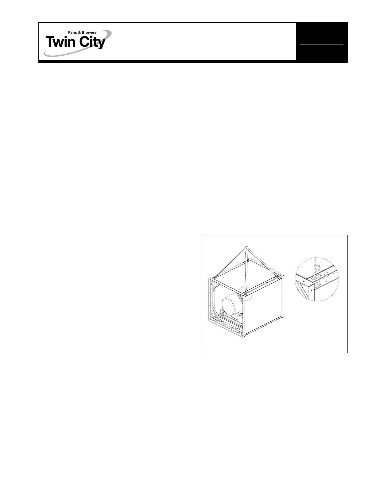
Units shipped completely assembled may be lifted with
slings and spreader bars. Use well-padded chains, cables
or nylon straps. On most units, lifting lugs are provided
for attaching chains (see Figure 1). Lift the fan in a fashion that protects the fan and fan coating from damage.
Never lift a fan by the inlet or discharge flange, shafting
or drives, wheel or impeller, motor or motor base, or in
any other manner that may bend or distort parts.
Partial or disassembled units require special handling. All
parts should be handled in a fashion which protects the
coatings and parts from damage. Components should
be handled such that forces are not concentrated and
bending or distortion cannot occur.
Figure 1. Lifting Lug Locations
Instructions given in the body of this manual are general in
nature and apply to a variety of models manufactured by
Twin City Fan & Blower. Most units can be installed and
maintained with the instructions given. Additional product
and engineering information is available at www.tcf.com.
Special applications may require additional information. These
instructions are supplied in the form of attached appendices.
Use the instructions in the appendix if the directions in this
manual differ from instructions in the appendix.
As always, follow good safety practices when installing,
maintaining and operating your air moving equipment. A
variety of safety devices are available. It is the user’s
responsibility to determine adequate safety measures and
to obtain the required safety equipment.
Shipping and Receiving
All Twin City Fan & Blower products are carefully constructed and inspected before shipment to insure the highest standards of quality and performance.
Compare all components with the bill of lading or packing
list to verify that the proper unit was received.
Check each unit for any damage that may have occurred in
transit. Any damage should be reported immediately to the
carrier and the necessary damage report filed.
NOTE: When lifting, the
straps/chains should be at a
minimum angle of 45°
Housing should be lifted using straps and spreaders. Do
not distort housing or side plates when lifting.
Short Term Storage
If fan installation is to be delayed, store the unit in a
protected area. Protect the fan and motor bearings from
moisture and vibration (or shock loading).
Long Term Storage
Prior to Storage – Motor bearings are to be greased at
the time of going into extended storage per the motor
manufacturer’s specifications.
©2014 Twin City Fan Companies, Ltd.
Page 2
Storage Procedure – Fans should be stored indoors
whenever possible where control over temperature,
shock and dust is reasonably maintained. If units are to
be stored outside in the elements, they should be covered with a water-resistant material. Stored equipment
should be stored on a clean, dry floor or blocked up
off the ground on blocks to prevent unit from setting in
any water or directly on the ground. If shock or vibration
will be present during storage, the unit may need to be
placed on some type of vibration dampening material
to aid in preventing brinelling of the bearing surfaces.
Periodic Check – On a monthly interval, the equipment
should be checked to ensure that it has remained in
an acceptable stored condition. After verifying the fan is
disconnected from the electrical supply, the fan wheel
should be rotated several times by hand while adding
enough grease to replenish the bearing surfaces with
fresh grease and to maintain a full bearing cavity. Grease
used must be compatible with that already supplied in
the motor and fan bearings. The fan impeller should
be left at approximately 180 degrees from that of the
previous month to prevent the shaft and impeller from
taking a set in one position. Storage records should
be maintained which indicate the above requirements
have been followed. Consult the motor manufacturer for
proper storage, space heater connection and lubrication
if the unit was supplied with one.
Start-Up – When the unit is removed from storage, all
bearing grease should be purged and replenished with
fresh grease as per the lubrication decal. The motor
resistance should be measured to verify it is still at a
satisfactory level compared to the value recorded prior
to storage.
Foundations and Supporting Structures
Floor mounted fans should be installed on a flat, level
surface with sufficient structure support. Support shall
be suitable for static and dynamic loads and foundation
frequencies be separated at least 20% from the rotational speed/speed ranges.
If the fans are mounted in a structure, the support
should be placed under the enclosure inlet and outlet
edges as a minimum. The fan mounting surfaces or
beams must be flat and level. Structural resonance
should be at least 20% from the fan operating speed,
when considering the weight of all fans and accessories.
Any ducting and/or dampers with sleeves should have
independent support; do not use the fan for support.
Isolating the fan from ductwork with flex connections
eliminates transmission of vibration.
1. Sufficient structure must be provided to support
weight of fan assembly.
2. Sufficient restraint must be provided to resist the
pressure force against the fans. Typically fans are
assembled in an application in a modular fashion with
multiple fans working in parallel. The cumulative thrust
force must be restrained to prevent the fan assemblies
from leaning or tipping forward. The force acting on
the fan assemblies is calculated as shown below.
Thrust force (lb
27.68
H x W x N x P
f) =
s
Where
P
s = Maximum operating static pressure (in. w.g.)
W = Width of each individual fan (in.)
H = Height of each individual fan (in.)
N = Quantity of fans in system
27.68 = conversion factor for in. w.g. to PSI
Example
Parallel fan system employing nine (9) – Size 182 fans
in a 3 x 3 configuration. (3 fans high x 3 fans wide)
System pressure is 5 inches of water column.
Outside dimension of fan housing = approx. 38 in. by
38 in.
Thrust force (lb
27.68
Thrust force (lb
27.68
NOTE:
The thrust force is distributed evenly across
H x W x N x P
f) =
38 x 38 x 9 x 5
f) =
s
= 2348 (lbf)
the front surface of the parallel fan system.
3. Recommend attachments to the sides and top of the
parallel fan system incorporating some form of spring
support, i.e. rubber snubbers/isolators or springs. Such
devices should be attached to prevent significant point
loading on an individual fan. They should be located
on the side of the parallel fan system at the top corner and along the top every 2 fans or less.
a. When the fans are rigidly mounted to the base, an
assumption can be made that half of the thrust
load will be supported at the base, and the supports added at the top of the fan need to carry a
minimum of one half of the thrust load.
b. When the fans are supported on an isolation base
or isolators, it will be necessary to add thrust
restraints around the periphery of the fan assembly
to support the entire thrust load. Flex connections are required when using isolators or isolation
base.
c. Attachments to the fan can be made utilizing the
factory mounting holes. Recommend that the gage
of the materials be checked for tear out strength
in thrust applications. If necessary utilize multiple
mounting hole locations to distribute the load.
2
Twin City IM-495
Page 3
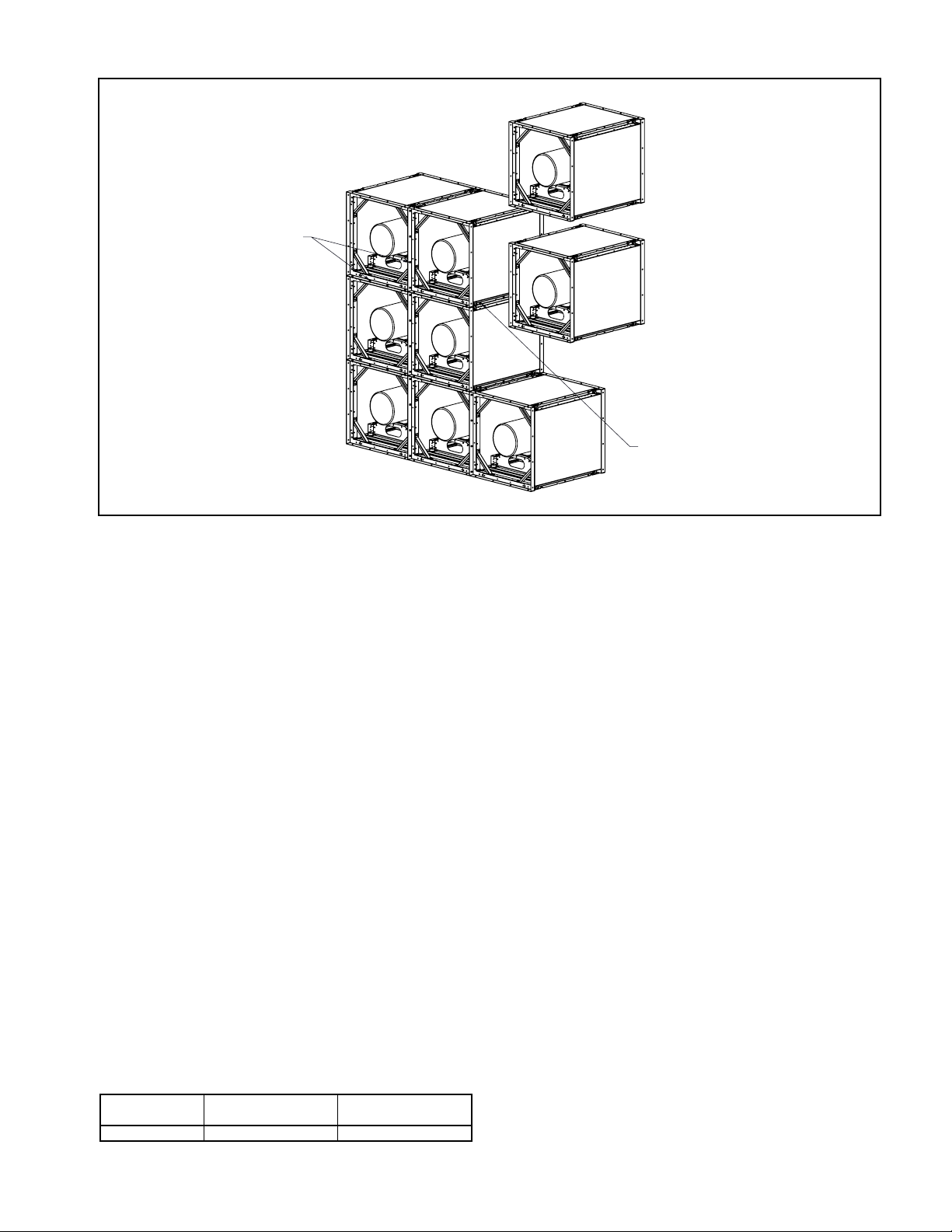
Figure 2.
3/8-16 x 0.75 Screws & Nuts
axial anges where accessable
front and back anges
3/8-16 x 0.75 Screws & Nuts
Fan Installation – Factory Assembled Units
Follow proper handling instructions given earlier.
1. Move the fan to the final mounting position.
2. Remove skid, crates, and packing materials carefully.
3. If supplied, place vibration pads or isolation base on
mounting bolts. Line up holes in fan base with bolts.
4. Place fan on mounting structure. Carefully level unit
using shims as required at all mounting hole locations. Bolt down the unit.
Assembly of Fans
1. Fans must be securely bolted to a base either directly
through the factory mounting holes or with a properly
designed clip. Final bolting of each individual row of
fans to the support structure or base should be done
after the individual fans are bolted together as a row.
NOTE: A thin gasket or caulk may be used to prevent
undesired air leakage and noise
2. The bolts to be snugged up on vertical sections for the
first row. Once all fasteners are in place, the bolts shall
be tightened to torque values in table. See Table 1.
3. The bolts holding the fan to the supporting structure
can now be torqued.
4. The second row and succeeding rows can be installed
using the same assembly steps as the first row.
5. Sealing around the perimeter should be accomplished
using a flexible material.
Table 1. Torque Values MPLFN/MPLFS/MPLQN/MPLQS
Fasteners
Size
3/8 – 16 UNC
Net Type
Nylock 16 – 17
Torque Values
(ft lbs)
Electrical Wiring of Fans
The customer is required to investigate and install
equipment in compliance with all local electrical and
safety codes for the equipment location. Twin City Fan &
Blower requires all power cabling be located away from
the rotating impeller and fastened to the inside of the
fan housing. Wiring must be routed away from the motor
to reduce potential contact with hot or greasy surfaces.
When a fan is supplied with an outlet damper, wiring
the electrical supply to the motor requires routing the
supply through the damper housing frame. Knockouts of
various sizes are provided in the damper housing frame to
accommodate cable connectors or raceway (see figure 3).
Fan Operation - Safety
For general safety practices for air moving equipment,
see AMCA Catalog 410.
Twin City Fan & Blower has many safety accessories
available. These safety devices include (but are not
limited to) inlet and discharge screens. The use, abuse,
or non-use of safety devices is the responsibility of the
purchaser.
Facility-related safety conditions include fan accessibility and location. How easily can non-service personnel
access the unit? Is the fan in a hazardous duty environment? Was the unit ordered for this duty? Other
concerns must also be addressed. All fans should be
powered through switches which are easily accessible
to service personnel from the fan. Every switch should
have the ability to be “locked-off” by the service person
and the key to be retained by this person to prevent
accidental power of the fan while service is in process.
Twin City IM-495 3
Page 4

Operation Check List
Verify that proper safety precautions have been followed:
□ Electrical power must be locked off.
Check fan mechanism components:
□ System connections are properly made and tightened. □
□ Bearings are properly lubricated.
□ Wheel, drives and fan surfaces are clean and free
of debris.
□ Rotate the impeller by hand to verify it has not shifted
in transit.
□ Check fan/wheel overlap. (See Figure 4.)
Figure 4. Wheel-Funnel Overlap
A
DIA
B
MPLFN/MPLFS/MPLQN/MPLQS
Size
1
15
165
182/18
200/200C
222/222C
Check fan electrical components:
□ Motor is wired for proper supply voltage.
□ Motor was properly sized for power and rotational
inertia of rotating assembly.
□ Motor is properly grounded.
□ All leads are properly insulated.
Trial “bump”:
□ Turn on power just long enough to start assembly
rotating.
□ Check rotation for agreement with rotation arrow.
Does the assembly make any unusual noise?
(See Figure 5.)
□ Correct any problems which may have been found.
(Follow safety guidelines - shut power off.) Perform
checklist again until unit is operating properly.
□ Run unit up to speed.
A B Size A B
22
0
2C
12.75 0.130
15.62 0.172
17.18 0.203
19.00 0.38
20.82 0.41
23.16 0.45
2
45/245
270/270C
300/300C
330/330C
365/365C
C
25.51 0.50
28.11 0.55
31.23 0.61
34.36 0.67
38.00 0.75
Verify fastener tightness. These may have loosened during shipment or installation.
□ Setscrews attaching wheel hub to shaft.
□ Nuts on inlet funnel.
□ Nuts and bolts holding motor.
□ Nuts holding housing frame to base and base to
ground.
□ Bolts in taper-lock bushings.
□ Grease line connections.
After one week of operation, check all nuts, bolts and
setscrews and tighten if necessary.
Figure 5. Proper Wheel Rotation
a
t
i
t
o
o
n
R
MPLFN, MPLFS,
MPLQN, & MPLQS
Wheels
Maintenance of Fans
This section contains general maintenance instructions
for your Twin City Fan & Blower unit. For specific information about maintenance of components, particularly
for special application fans, see the attached documents.
General Motor Maintenance
The three basic rules of motor maintenance are keep the
motor clean, dry and properly lubricated.
Keeping motors and windings clean is important because
dirt and dust serve as thermal insulators. Heat normally
dissipated by the motor is trapped causing overheating
and/or premature failure. Blow dust and dirt out of windings and off the motor periodically. Use low pressure (50
psig) airstream so that winding damage does not occur.
Keep the area surrounding the motor open so the air can
circulate through the motor cooling fan. Follow normal
maintenance schedule given to the right.
Motors should be kept dry to avoid electrical short circuits. Motors kept in storage for long periods of time
can have moisture condense on the windings. Be certain
the motor is dry before using.
Some smaller motors are lubricated for life. Motor bearing lubrication, if required, must follow a rigorous schedule. Motors less than 10 hp running about eight hours
a day in a clean environment should be lubricated once
every five years; motors 15 to 50 hp, every 3 years;
and motors 50 to 150 hp, yearly. For motors in a dusty
or dirty environment or running 24 hours a day, divide
the service interval by 2. If the environment is very dirty
or high temperatures exist, divide the service interval by
4. Lubrication requirements are normally attached to the
motor. Do not overlubricate.
4
Twin City IM-495
Page 5

Wheel and Shaft Maintenance
Periodically inspect the shaft and wheel for dirt buildup,
corrosion, and signs of excess stress or fatigue. Clean
the components and, when appropriate, apply new coatings. (Any addition of coatings or weld can create an
imbalance.) Check the balance of the assembly.
Structural Maintenance
All structural components or devices used to support or
attach the fan to a structure should be checked at regular intervals. Vibration isolators, bolts, foundations, etc.,
are subject to failure from corrosion, erosion, and other
causes. Improper mounting can lead to poor operation
characteristics or fan fatigue and failure.
Check metallic components for corrosion, cracks, or
other signs of stress. Concrete should be checked to
ensure the structural integrity of the foundation.
Troubleshooting Guidelines
Use current safety practices when investigating fan or
system performance problems. General safe practices
and performance troubleshooting guidelines can be
found in AMCA Publications 410 and 202, respectively.
Fan application and field measurement procedures can
be found in AMCA Publications 201 and 203.
Troubleshooting Performance Problems
The lists below indicate possible areas to check when air
or sound values do not match expectations. Most fan problems can be pinpointed to one of these common causes.
Vibration Problems:
1. Misalignment of drive components.
2. Poor foundations or mounting structure (resonances).
3. Foreign material attached to rotating components.
4. Damaged rotating components (bearings, shaft, fan,
wheel).
5. Broken, loose or missing setscrews.
6. Loose bolts.
7. Vibration transmitted by another source.
8. Water accumulating in airfoil blades.
9. Fan is operating in stall or unstable flow region.
NOTE: All fans manufactured by Twin City Fan &
Blower are factory balanced prior to shipment. Handling
and movement of the fan during shipment may cause
the rotating assembly to shift. Balance should be
checked once the fan is installed. If a final trim balance
is required, it is the end user's responsibility to bring the
fan back to factory specifications. Final trim balancing is
not the responsibility of Twin City Fan & Blower.
Motor Problems:
1. Incorrect wiring.
2. Speed of fan too high.
3. Parts improperly installed - binding.
4. Bearings improperly lubricated.
2
5. WR
capability of motor too low for application.
6. Protection devices may be improperly sized.
Air Capacity Problems:
1. Resistance of system not at design rating. If resistance is lower than expected, both airflow and
horsepower may be up. If resistance is higher than
anticipated, air volume will be down.
2. Fan speed is not at design speed.
3. Air density not at design values. Also check air performance measurement techniques/procedures.
4. Devices for air modulation are closed or plugged.
Also check filters.
5. Wheel mounted improperly or is rotating in reverse.
6. Parts of system or fan have been damaged or need
cleaning.
Noise Problems:
1. Air performance is incorrect and fan is not at design
point of operation. Fan forced to operate in an
unstable flow region.
2. Bearing failure. Check bearings (lubrication).
3. Supply voltage high or inconsistent supply frequency.
Adjustable frequency controllers can generate motor
noise.
4. Objects which are installed in a high velocity airstream can generate noise. This includes flow sensors, turning vanes, etc.
5. Poor fan inlet conditions.
6. Acoustics or sound measurement procedure incorrect.
Motor Lubrication – The major cause of motor bearing
failure is contamination of grease, insufficient grease, or
incompatibility of grease. If a fan is to be stored for
any length of time at the job site and the bearings are
regreasable, the motor bearings should immediately be
filled with grease while rotating the fan and then the
bearings should be regreased and rotated monthly. This
will prevent moisture, which condenses within the bearing, from corroding the raceways. Most greases used on
motor bearings are lithium base. Use the greases shown
in the motor information. Do not mix the bases without
completely purging out the initial grease.
Initially, follow the lubrication instruction in the motor
information. The frequency of lubrication should be
adjusted depending on the condition of the old grease
being purged. This is the responsibility of the user. If
the grease is dirty, the lubrication frequency should be
more often.
a. Noise – If a bearing is increasing in noise intensity
and/or vibration, it will probably result in failure.
b. Temperature – If a bearing temperature begins to
gradually rise, it will generally result in failure. A
bearing can operate up to 200 degrees and operate
satisfactorily if the temperature remains constant and
the bearing receives adequate lubrication. Remember
that a roller bearing under the same load and speed
will be somewhat more noisy and run warmer than a
ball bearing. This is normal.
Rough handling and/or dropping a fan can result in brinelling the bearing. This appears as a clicking noise at
first, then gradually worsens until failure.
Twin City IM-495 5
Page 6

Limitation of Warranties and Claims
Seller warrants to the original purchaser that the goods
sold hereunder shall be free from defects in workmanship and material under normal use and service (except
in those cases where the materials are supplied by the
buyer) for a period of one year from the date of original
installation or eighteen (18) months from the date of
shipment, whichever occurs first. The liability of seller
under this warranty is limited to replacing, repairing, or
issuing credit (at cost, F.O.B. factory and at seller’s
discretion) for any part or parts which are returned by
buyer during such period provided that:
a. seller is notified in writing within ten (10) days fol-
lowing discovery of such defects by buyer, or within
ten (10) days after such defects should reasonably
have been discovered, whichever is less;
b. the defective unit is returned to seller, transportation
charges prepaid by buyer.
c. payment in full has been received by seller or said
products; and
d. seller’s examination of such unit shall disclose to its
satisfaction that such defects have not been caused
by misuse, neglect, improper installation, repair,
alteration, act of God, or accident.
e. seller cannot guarantee sound pressure levels or
dBA.
No warranty made hereunder shall extend to any seller
product whose serial number is altered, effaced or
removed. Seller makes no warranty, express or implied,
with respect to motors, switches, controls, or other
components of seller’s product, where such components
are warranted separately by their respective manufacturers. THIS WARRANTY IS EXPRESSLY IN LIEU OF
ALL OTHER WARRANTIES, EXPRESS OR IMPLIED,
WHETHER STATUTORY OR OTHERWISE, INCLUDING
ANY IMPLIED WARRANTY OF MERCHANTABILITY OR
FITNESS FOR A PARTICULAR PURPOSE. In no event
shall seller be liable to buyer for indirect, incidental collateral, or consequential damages of any kind.
(BUYER’S FAILURE TO PAY THE FULL AMOUNT DUE
WITHIN SIXTY (60) DAYS OF DATE OF INVOICE SHALL
OPERATE TO RELEASE SELLER FROM ANY AND ALL
LIABILITY OR OBLIGATION ARISING PURSUANT TO
ANY WARRANTY, EXPRESS OR IMPLIED, WHETHER
STATUTORY OR OTHERWISE, INCLUDING ANY IMPLIED
WARRANTY OR MERCHANTABILITY OR FITNESS FOR
A PARTICULAR PURPOSE, MADE IN CONNECTION
WITH ANY CONTRACT FORMED HEREUNDER. BUYER
AGREES THAT SUCH FAILURE TO PAY SHALL
CONSTITUTE A VOLUNTARY WAIVER OF ANY AND ALL
SUCH WARRANTIES ARISING PURSUANT TO SUCH
CONTACT.)
6
Twin City IM-495
Page 7

TWIN CITY FAN & BLOWER | WWW.TCF.COM
5959 Trenton Lane N | Minneapolis, MN 55442 | Phone: 763-551-7600 | Fax: 763-551-7601
 Loading...