

Twin City IM-4860NF User Manual
Hooded Propeller Roof Fans
(Non-Filtered)
INSTALLATION & ASSEMBLY MANUAL
IM-4860NF
September 2009
Panel End Assy, Male 1 1 1 1 1 1 1 1 1 1 1
14 16 18 21 24 30 36 42 48 54 60
Panel End Assy, Female 1 1 1 1 1 1 1 1 1 1 1
Hood Panel 2 2 2 2 3 5 5 6 7 7 8
Hood Side Rail Assy 2 2 2 2 2 2 2 2 2 2 2
Hood Gusset 0 0 0 0 0 4 4 4 4 4 4
Hood Clip 0 0 0 0 0 0 0 0 0 16 18
Hood Mount Bar 2 2 2 2 2 2 2 2 2 2 2
Bird Screen Assy, Fixed 2 2 2 2 2 2 2 2 2 2 2
Bird Screen Assy, Removable 2 2 2 2 2 2 2 2 2 2 2
HDWRKIT-LH01 Hardware Kit #1 - Hood
Qty Item
12 Cap Screw, Serrated Flange Hex, 3/8-16 x .75
20 Hex Nut, Serrated Flange, 3/8-16
4 Cap Screw, Serrated Flange Hex, 3/8-16 x 1.25
72 Screws, #12
Fan Size/Qty
HDWRKIT-LH06 Hardware Kit #6 - Mesh Bird Screen (Size 24 to 60)
Qty Item
10 Cap Screw, Serrated Flange Hex, 5/16-18 x .75
6 Nut Clip, 5/16
4 Hex Nut, Serrated Flange, 5/16-18
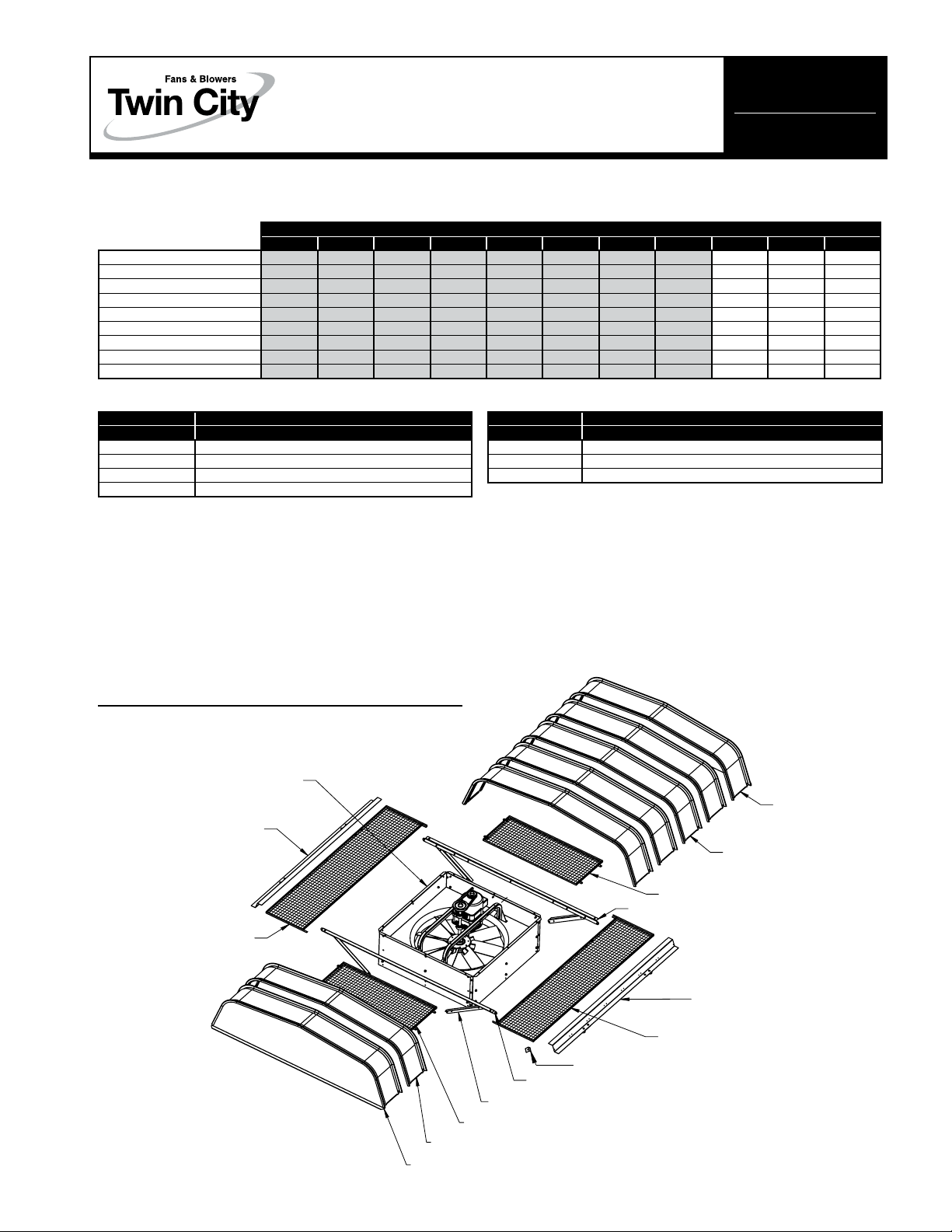
• Fan sizes 14 to 42 are shipped fully assembled, unless otherwise specified.
• A minimum of two people are required for assembly. Before starting, review these instructions.
• The following tools are required:
- Powered screwdriver (preferred), or drill
- 3/8, 7/16, 1/2, 9/16 wrenches and sockets
- 5/16" nut driver bit for powered screwdriver
- Awl, for hole alignment
Inspect for missing or damaged parts
Fan Base Assy
Hood Side Rail Assy
Bird Screen Assy, Fixed
Hood Panel
End Panel Assy, Female
©2009 Twin City Fan Companies, Ltd.
Hood Clip
(Size 54 and 60)
Hood Mount Bar
Hood Gusset
Bird Screen Assy, Removable
Hood Panel
Bird Screen Assy, Removable
Hood Mount Bar
Hood Side Rail Assy
Bird Screen Assy, Fixed
End Panel Assy
Male
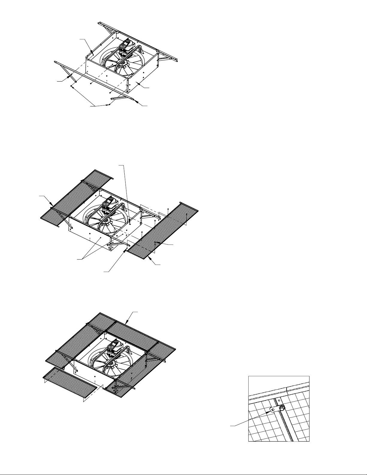
3/8-16 x .75
Cap Screw
Fasteners are already
installed (four places)
Nut
Fan Housing
Side Panel
Hood Mount
Bar
Step 1 – Install Hood Mount Bars
Fasteners (Kit #1):
Cap Screw, Serrated Flange, 3/8-16 x 0.75
Hex Nut, Serrated Flange, 3/8-16
A. Assemble Hood Mount Bars on both sides
of the fan housing, using cap screws and
nuts.
B. Assemble four Hood Gussets using cap
screws and nuts. The bottom holes on the
gussets attach to the curb stop fasteners,
which are already installed on the fan housing. One at a time, remove the screws and
attach the gussets.
Bird
Screen
Assy,
Fixed
Fan Housing
Side Panels
5/16-18
Hex Nuts
5/16-18
Nut Clips
Cap Screws
Bird Screen
Assy, Fixed
Bird Screen
Assy, Removable
Step 2 – Install Fixed Screens
Fasteners (Kit #6):
Cap Screw, Serrated Flange, 5/16-18 x 0.75
Hex Nut, Serrated Flange, 5/16-18
Nut Clips, 5/16-18
A. Install nut clips onto Fan Housing Side Panel
flanges as shown.
B. Install two Fixed Screen Assemblies using
cap screws and nuts. Do not fully tighten
these fasteners. They will be fully tightened
in the next step.
5/16-18
Step 3 – Install Removable Screens
A. Install two Removable Screen Assemblies.
After positioning the assemblies, rotate the
locking tabs in place and tighten.
B. Fully tighten the Fixed Screen assembly fas-
teners from the previous step.
Detail of locking tabs
Locking Tab,
rotate into place
and tighten
2 Twin City IM-4860NF Twin City IM-4860NF 3
 Loading...