

Page 1
Hooded Propeller Roof Fans
(Filtered Supply)
INSTALLATION & ASSEMBLY MANUAL
IM-4860FS
September 2009
Panel End Assy, Male 1 1 1 1 1 1 1 1
21 24 30 36 42 48 54 60
Panel End Assy, Female 1 1 1 1 1 1 1 1
Hood Panel 2 3 5 5 6 7 8 9
Hood Side Rail Assy 2 2 2 2 2 2 2 2
Filter Rail Assy, Long 2 2 2 2 2 2 2 2
Filter Rail Assy, Short 0 2 2 2 2 2 2 2
Filter Rail 2 2 2 2 2 2 2 2
Hood Gusset 0 0 4 4 4 4 4 4
Stiffener Angle 2 2 2 2 2 2 2 2
Filter Stop Plate 2 2 2 2 2 2 2 2
Hood Clip 0 0 0 0 0 0 18 20
Hood Mount Bar 2 2 2 2 2 2 2 2
Filter Size A 4 6 8 8 8 10 10 10
Filter Size B 2 4 4 4 4 4 8 8
HDWRKIT-LH01 Hardware Kit #1 - Hood
Qty Item
12 Cap Screw, Serrated Flange Hex, 3/8-16 x .75
20 Hex Nut, Serrated Flange, 3/8-16
4 Cap Screw, Serrated Flange Hex, 3/8-16 x 1.25
72 Screws, #12
Fan Size/Qty
HDWRKIT-LH07 Hardware Kit #7 - Filter Rail
Qty Item
22 Cap Screw, Serrated Flange, 5/16-18 x .75
16 Hex Nut, Serrated Flange, 5/16-18
6 Nut Clips, 5/16
• Fan sizes 21 to 36 are shipped fully assembled, unless otherwise specified.
• A minimum of two people are required for assembly. Before starting, review these instructions.
• The following tools are required:
- Powered screwdriver (preferred), or drill
- 3/8, 7/16, 1/2, 9/16 wrenches and sockets
- 5/16" nut driver bit for powered screwdriver
- Awl, for hole alignment
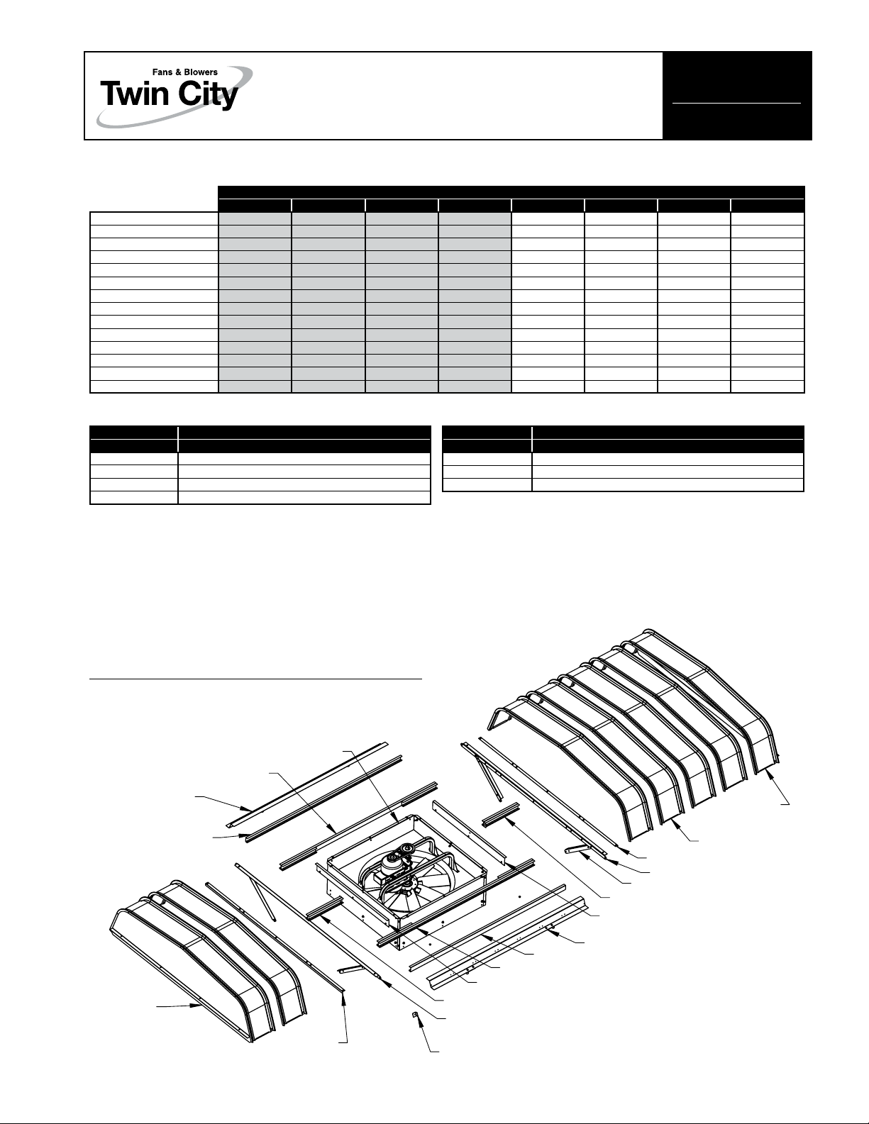
Inspect for missing or damaged parts
Fan
Base
Assembly
Stiffener
Angle
©2009 Twin City Fan Companies, Ltd.
Side Rail
Assembly
Panel End
Assembly,
Female
Hood
Filter Rail
Filter
Rail
Assembly,
Long
Filter Rail
Filter Rail Assembly, Long
Filter Stop Plate
Filter Rail Assembly, Short
Hood Mount Bar
Hood Clip
(Size 54 and 60)
Hood Panel
Stiffener Angle
Hood Mount Bar
Hood Gusset
Filter Rail Assembly, Short
Filter Stop Plate
Hood Side Rail Assembly
Panel End
Assembly,
Male
Page 2
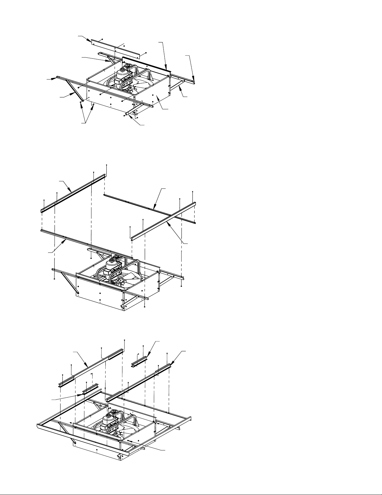
Hood Gusset
Hood
Mount
Bar
Hood Gusset
Fasteners are
already installed
(four places)
Filter
Stop
Plate
Filter
Stop
Plate
Mount
Fan Housing
Side Panel
Hood Gusset
Hood
Bar
Hood
Gusset
Step 1 – Install Hood Mount Bars
and Filter Stops
Fasteners (Kit #1):
Cap Screw, Serrated Flange, 3/8-16 x 0.75
Hex Nut, Serrated Flange, 3/8-16
A. Assemble Hood Mount Bars and Filter Stop
Plates on both sides of the fan housing,
using cap screws and nuts.
B. Assemble four Hood Gussets using cap
screws and nuts. The lower fasteners on the
gussets attach to the curb stop fasteners,
which are already installed on the fan housing. One at a time, remove the screws and
attach the gussets.
Channel
Stiener
Angle
Filter
Long
Assembly
Rail
Stiener
Angle
Short
Rail
Assembly
Filter
Channel
Long
Rail
Assembly
Step 2 – Install Filter Channels and
Stiffeners
Fasteners (Kit #7):
Cap Screw, Serrated Flange, 5/16-18 x 0.75
Hex Nut, Serrated Flange, 5/16-18
A. Assemble two Filter Channels to Hood Mount
Bars using cap screws and nuts.
B. Assemble two Stiffener Angles to the Filter
Channels using cap screws and nuts.
Step 3 – Install Filter Rail
Assemblies
Fasteners (Kit #7):
Cap Screw, Serrated Flange, 5/16-18 x 0.75
Hex Nut, Serrated Flange, 5/16-18
Nut Clip, 5/16-18
Short
Rail
Assembly
A. Install nut clips onto the fan Housing Side
Panel flanges as shown.
B. Assemble two Long Rail Assemblies using
cap screws and nuts.
C. Assemble two Short Rail Assemblies using
cap screws and nuts.
Nut Clips
2 Twin City IM-4860FS Twin City IM-4860FS 3
Page 3

Hood
Side Rail
Assembly
3/8-16 x 1.25
Cap Screws
and Hex Nuts
End Panel Assembly
Male Type
Hood
Side Rail
Assembly
Step 4 – Install Hood Side Rails
Fasteners (Kit #1):
Cap Screw, Serrated Flange, 3/8-16 x 1.25
Hex Nut, Serrated Flange, 3/8-16
A. Install two Hood Side Rail Assemblies to
the Hood Mount Bars using cap screws and
nuts. Do not fully tighten fasteners. They will
be tightened in Step 7.
Step 5 – Install End Assy (Male)
Fasteners (Kit #1):
Screws, #12
A. Assemble End Panel Assembly (male type)
using two #12 screws.
Important - This
flange must
be male
Hood Panels
End View of Panel
End View of Panel
Male Flange
(Narrow)
Female Flange
(Wide)
Step 6 – Install Hood Panels
Fasteners (Kit #1):
Screws, #12
A. Install the Hood Panels using #12 screws.
B. On Sizes 54 and 60, hood clips must be
installed at each interlocking rib while installing the panels. Position the Hood Panel in
place and reach underneath to slide the clip
into place.
For Sizes 54 and 60,
install hood clips at each rib.
#12
Hood
Panels
Screws
Hood Clip
Hood Side
Rail Assy
Page 4

End Panel Assembly
TM
®
Female Type
Step 7 – Install End Assembly
(Female)
Fasteners (Kit #1):
Screws, #12
A. Assemble End Panel Assembly (female type)
using four #12 screws. On sizes 54 and 60,
install hood clips at flange joints.
B. Fully tighten the Hood Mount Bar/Side Rail
fasteners from Step 4.
This flange must
be female
Step 8 – Install Filters
A. Remove both Filter Retainers from End
Panels. Retain hardware.
B. Install Filters as shown.
C. Reinstall both Filter Retainers.
Filter
Retainers
Filter Configurations
Fan Size 21
A
A
BB
AA
Fan Size P/N Size Quantity P/N Size Quantity
21
FILTER2A-LH21 23.81 x 9.75 4 FILTER2B-LH21 29.19 x 8.88 2
24
FILTER2A-LH24 19.88 x 13.50 6 FILTER2B-LH24 16.00 x 13.38 4
30
FILTER2A-LH30 20.88 x 15.50 8 FILTER2B-LH30 20.00 x 21.06 4
36
FILTER2A-LH36 20.81 x 20.50 8 FILTER2B-LH36 23.00 x 18.25 4
42
FILTER2A-LH42 23.81 x 17.00 8 FILTER2B-LH42 26.00 x 21.38 4
48
FILTER2A-LH48 21.44 x 23.50 10 FILTER2B-LH48 29.00 x 24.38 4
54
FILTER2A-LH54 23.88 x 26.50 10 FILTER2B-LH54 32.13 x 13.69 8
60
FILTER2A-LH60 26.25 x 29.50 10 FILTER2B-LH60 35.00 x 15.00 8
Filter A Filter B
Fan Size 24 to 48
(Check table for quantities)
AAAA
A
B
B
A
AAAA
B
B
Fan Size 54 to 60
AAAA
A
B
B
B
B
AAAAA
BB
BB
.5MW09/09
 Loading...