

Twin City IM-4720FSS User Manual
MGI Modular Gravity Hood with Filters
(throat sizes 72" & smaller)
INSTALLATION & ASSEMBLY MANUAL
See Catalog 4720 for sizes that ship assembled.
IM-4720FSS
August 2013
Qty
24 Cap Screw, Serrated Flange, 1/4-20 x 5/8"
24 Hex Nut, Serrated Flange, 1/4-20
Qty
4 Doubler plates
4 Cap Screw, Serrated Flange, 5/16-18 x 3/4"
4 Hex Nut, Serrated Flange, 5/16-18
Note: Not always required.
Qty
8 Cap Screw, Serrated Flange, 5/16-18 x 3/4"
8 Hex Nut, Serrated Flange, 5/16-18
Hardware Kit #1A
Item
Hardware Kit #1C
Item
Hardware Kit #3
Item
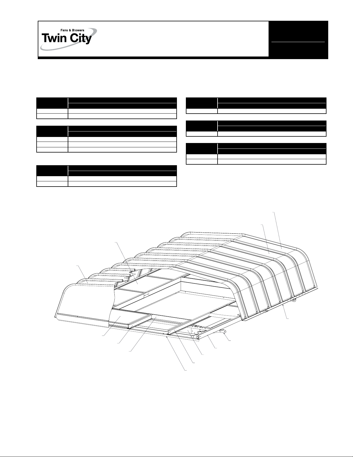
Figure 1.
End Filter
Hood End Panel
Assy (Male Rib)
Qty
40 Screws, #12 x 3/8"
Qty
A/R Hood Clips (Only for hood panels longer than 108")
Qty
20 Cap Screw, Serrated Flange, 5/16-18 x 3/4"
20 Hex Nut, Serrated Flange, 5/16-18
Hardware Kit #4A
Item
Hardware Kit #5
Item
Hardware Kit #6A
Item
Hood End Panel
Assy (Female Rib)
Hood Panel
Side Filter
Filter Rail, Type -C-
Filter Stop Plate
Hood Rail Assy
Hood Mount Bar
Filter Rail, Type -A-
Base Assy
Filter Rail, Type -B-
Stiffener Angle
©2013 Twin City Fan Companies, Ltd.
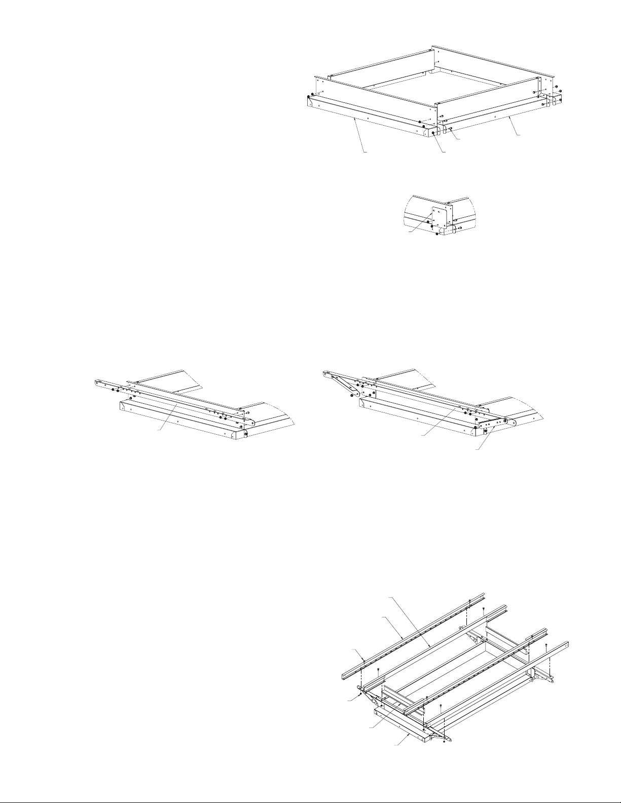
Step 1 – Base Assembly
Curb Base Side
Figure 2.
Fasteners (Kit #1A and #1C) – Note: There may
be extra fasteners.
Lay out the Curb Base Side and Curb Base
End in approximate location to each other. See
Figure 2. Use (3) 1/4-20 fasteners for 5" base
height and (4) 1/4-20 fasteners for 12" base
height. Leave top two holes open on the Base
End. Note: Hand tighten only until Step 3. On
some hoods, a Doubler Plate is required. See
Detail A in Figure 2.
Curb Base End
Doubler Plate
DETAIL A
* When Kit 1C provided.
Screw
Hex Nut
Step 2 – Hood Mount Bars
Fasteners (Kit #1A and #1C)
Loosely assemble Hood Mount Bars on both sides of the Curb Base Ends using (4) 1/4-20 fasteners per side. On
hoods using a Doubler Plate, mount Brace using 5/16-18 hardware. See Figure 3b.
Figure 3a. Figure 3b.
Hood Mount Bar
Hood Mount Bar
Brace
Step 3 – Caulk
Caulk inside corners of base assembly and tighten all fasteners. Install assembly onto roof curb before proceeding.
Ensure that assembly is properly anchored to roof curb.
Step 4 – Filter Rails
Fasteners (Kit #6A) – Note: There may be
extra fasteners.
Attach Filter Channel, Type -A- to the
Hood Mount Bar using cap screws and
nuts (hand tight). Lay Filter Channels,
Type -B- onto assembly and wedge Filter
Stop Plate between them and the Base
Assembly. Assemble with cap screws and
nuts (hand tight).
Figure 4.
Filter Rail, Type -B-
Filter Rail, Type -A-
Screw, Hex Head
Hex Nut, Flanged
Filter Stop Plate
Base Assy
2 Twin City IM-4720FSS
 Loading...