

Page 1

Gravity Relief/Intake Ventilators
INSTALLATION, OPERATION & MAINTENANCE MANUAL
Models
GRV, TEL, TIL, LUG
IM-4700
June 2014
Model GRV
Model LUG
Twin City Fan & Blower Catalog 4720 provides additional information on this equipment. This catalog can be found
at www.tcf.com or by contacting your local Twin City Fan & Blower sales representative.
Models TEL & TIL
Nomenclature
GRV – 120 B
GRV = Gravity Relief/Intake Ventilator Design Vintage (GRV)
TEL = Exhaust Louvered
TIL = Intake Louvered Throat Dimension (TEL/TIL)
LUG = Low Profile Upblast Gravity Exhaust Vent Size (LUG)
Nominal Throat Diameter (GRV)
090 = 9.00" 270 = 27.38"
120 = 12.13" 300 = 30.38"
160 = 16.25" 320 = 32.38"
180 = 18.25" 360 = 36.38"
210 = 21.25" 420 = 42.38"
240 = 24.25" 480 = 48.38"
©2014 Twin City Fan Companies, Ltd.
Page 2
Receiving, Inspection & Unpacking
When the equipment is received all items should be
carefully checked against the bill of lading to be sure all
crates and cartons have been received. Before accepting delivery, carefully inspect each carton or crate for
visible shipping damage. If any damage is noticed, the
carrier should make the proper notation on the delivery
receipt acknowledging the damage. Make notations of all
damage on all copies of the bill of lading and have all
copies countersigned by the delivering carrier. The carrier should also fill out a Carrier Inspection Report. The
factory Traffic Department should then be contacted.
General Installation
CAUTION: Sheet metal parts, screws, clips and similar
items inherently have sharp edges, and it is necessary
that the installer and service personnel exercise caution.
The installation of this equipment shall be in accordance
with the regulations of authorities having jurisdiction and
all applicable codes.
File claim for damage with the carrier. Physical damage
to the unit after acceptance is not the responsibility of
Twin City Fan Companies, Ltd.
Unpack each carton or crate and verify that all required
parts and proper quantities of each item have been
received. Refer to drawings for part descriptions. Report
shortages or missing items to your local representative
to arrange for replacement parts
Due to availability of carriers and truck space, it is not
possible to guarantee that all items will be shipped
together. Verification of shipments must be limited to
only those items on the bill of lading.
This equipment is to be installed by an experienced
installation company and fully trained personnel.
The mechanical installation of the exhaust ventilator
consists of making final connections between the unit,
building services, and duct connections.
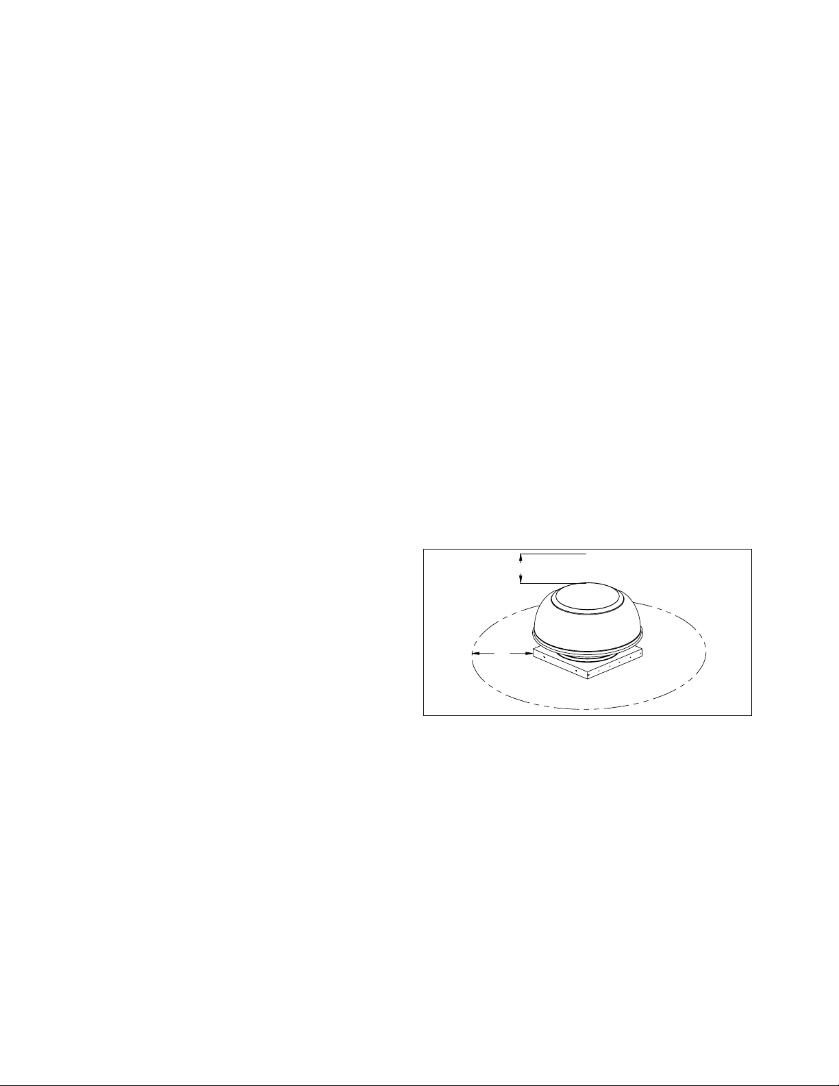
Service Clearance
Adequate clearance around the unit should be kept for
safety, maintenance, and proper unit operation.
A minimum clearance of 36" to 48" is recommended
to insure proper ventilation. Unit should be installed
remote from building air exhausters to inhibit ingestion
of exhaust air into building.
Allow a minimum of 24" clearance above the unit for
removal of unit top cover. Note: Clearance may have to
be increased if using the hinged curb option.
The unit must not be installed under any obstructions.
Unit Installation
General
1. The unit should be roof mounted only to an appropriately sized roof curb or duct. See "Roof Curb
Installation" on page 3.
2. The base of the curb cap should be horizontal.
Figure 1. Service Clearances
24"
36"
Model GRV shown
Installation
1. Drill 8 holes (2 per side) into the roof curb through
the holes provided in the unit curb cap.
2. Bolt the unit to the roof curb through these holes
1
⁄4-20 self-tapping screws.
using
2 Twin City Fan IM 4700
Page 3

Roof Curb Installation
General
1. Roof curbs are shipped fully assembled. Leveling and
mounting on the roof structure are the responsibility
of the installing contractor. All curb installations must
comply with the established guidelines of the National
Roofing Contractors Association.
2. Curb flashing, cant strips, and general roofing materials are to be furnished by the contractor. Wood nailing strip is provided with standard curb; gasketing is
provided with self-flashing and straight-sided curbs.
3. The unit and curb accessories are designed to allow
vertical duct installation before unit placement. Duct
installation after unit placement is not recommended.
NOTE: Outside dimensions of roof curb top should be
1
⁄2" to 11⁄2" less than inside unit curb cap dimension
depending on thickness of flashing material used. If curb
hinge accessory is used, specify 1
1
⁄2" difference.
NOTE: On self-flashing and straight-sided curbs check
top of curb to make sure gasket has been applied
properly. Gasket should be firmly applied to top of curb
perimeter.
Curb Hinge Installation (Optional - GRV, LUG)
Installation
1. Place curb in proper location over roof opening.
2. Curb must be level. Shim curb as required to level curb.
3. Attach leveled curb to roof structure following industry accepted practice.
4. Install cant strips, roofing materials, flashing and
counterflashing in accordance with the established
guidelines of the National Roofing Contractors
Association. The finished roof, including counterflashing around the curb, must be installed prior to setting
unit on the curb.
General
1. The curb hinge option assists unit maintenance and
cleaning by allowing easy access to the underside of
the unit.
2. Pilot holes are provided in the unit curb cap for
attaching the curb hinge to the unit as standard. The
option is available factory or field installed.
Installation
1. Ensure the unit will not be restricted from pivoting
and that airflow to the unit is not restricted. (See note
under “Service Clearance.”)
2. Bolt the hinge to the unit curb cap through the holes
provided by using
1
⁄4-20 self-tapping screws (see
Figure 2).
3. Place the unit with the hinge on the roof curb and
align hinge holes with roof curb holes.
1
4. Now bolt the hinge to the roof curb using
⁄4-20 self-
tapping screws (see Figure 2).
Insect Screen (Optional)
Figure 2. Curb Hinge Installation
UNIT CURB CAP
(PREPUNCHED
MOUNTING HOLES)
CURB HINGE DETAIL
(END VIEW)
UNIT CURB
CAP
ROOF
CURB
Note: Roof curb to be 11/2" smaller than unit base (curb cap).
OFFSET
HINGE
1/4-20
SCREW
CURB HINGE,
PIANO
1/4-20 SCREW
ROOF CURB
1/4-20 SCREW
General
1. The insect screen is a separate part and should not
be confused with the bird screen. It contains a finer
screen and needs to be installed while the unit is
being fastened to the roof curb.
Installation
1. Place the insect screen assembly on top of the roof
curb.
2. When the unit is placed on and being bolted to the
roof curb the insect screen will be held in place
between the unit curb cap and the roof curb.
Twin City Fan IM 4700 3
Page 4

Backdraft Damper Installation (Optional - GRV, TEL, TIL)
1. Damper must be mounted prior to unit installation.
3. Damper should be installed inside curb on a nailing
strip or tray (see Figure 3).
4. Be sure knockout for power supply, in one corner of
the damper frame, is in the most convenient position
for connecting between power source and conduit
raceway of unit.
5. Before setting unit on curb, ascertain that the damper
is positioned horizontally and operative.
6. Damper motors (optional) are available for 115, or
208-230, 460V, or 575V. When power supply is threephase, the damper can be connected across any two
of the three phases. A power supply of 575V requires
a step-down transformer to 115V. Damper motor is
energized continuously when open.
1
NOTE: Outside dimensions of damper are
⁄8" less than
specified.
CAUTION: Installation of the damper will differ when
using the unit as a relief ventilator versus an intake. The
damper must be motorized when used with a GRV as
an intake ventilator.
Maintenance
1. Periodically inspect bird or insect screens to ensure
they are clean and not restricting airflow.
2. If using a backdraft damper on a GRV, TEL or TIL
Ventilator, ensure that it can operate freely.
Figure 3. Backdraft Damper Installation
KNOCKOUT FOR
POWER SUPPLY
ROOF CURB
BACKDRAFT DAMPER
(OPTIONAL)
MOUNTING SCREW
(FIELD SUPPLIED)
DAMPER TRAY
3. Make sure the butterfly dampers on an LUG operate
freely.
4. Periodically inspect filters on a TIL, if so equipped,
to ensure they are clean.
Limitation of Warranties and Claims
Seller warrants to the original purchaser that the goods
sold hereunder shall be free from defects in workmanship and material under normal use and service (except
in those cases where the materials are supplied by the
buyer) for a period of one year from the date of original
installation or eighteen (18) months from the date of
shipment, whichever occurs first. The liability of seller
under this warranty is limited to replacing, repairing, or
issuing credit (at cost, F.O.B. factory and at seller’s
discretion) for any part or parts which are returned by
buyer during such period provided that:
a. seller is notified in writing within ten (10) days fol-
lowing discovery of such defects by buyer, or within
ten (10) days after such defects should reasonably
have been discovered, whichever is less;
b. the defective unit is returned to seller, transportation
charges prepaid by buyer.
c. payment in full has been received by seller for said
products; and
d. seller’s examination of such unit shall disclose to its
satisfaction that such defects have not been caused
by misuse, neglect, improper installation, repair,
alteration, act of God, or accident.
No warranty made hereunder shall extend to any seller
product whose serial number is altered, effaced or
removed. Seller makes no warranty, express or implied,
with respect to motors, switches, controls, or other
components of seller’s product, where such components
are warranted separately by their respective manufacturers. THIS WARRANTY IS EXPRESSLY IN LIEU OF
ALL OTHER WARRANTIES, EXPRESS OR IMPLIED,
WHETHER STATUTORY OR OTHERWISE, INCLUDING
ANY IMPLIED WARRANTY OF MERCHANTABILITY OR
FITNESS FOR A PARTICULAR PURPOSE. In no event
shall seller be liable to buyer for indirect, incidental collateral, or consequential damages of any kind.
(BUYER’S FAILURE TO PAY THE FULL AMOUNT DUE
WITHIN SIXTY (60) DAYS OF DATE OF INVOICE SHALL
OPERATE TO RELEASE SELLER FROM ANY AND ALL
LIABILITY OR OBLIGATION ARISING PURSUANT TO
ANY WARRANTY, EXPRESS OR IMPLIED, WHETHER
STATUTORY OR OTHERWISE, INCLUDING ANY IMPLIED
WARRANTY OR MERCHANTABILITY OR FITNESS FOR
A PARTICULAR PURPOSE, MADE IN CONNECTION
WITH ANY CONTRACT FORMED HEREUNDER. BUYER
AGREES THAT SUCH FAILURE TO PAY SHALL
CONSTITUTE A VOLUNTARY WAIVER OF ANY AND ALL
SUCH WARRANTIES ARISING PURSUANT TO SUCH
CONTACT.)
TWIN CITY FAN & BLOWER | WWW.TCF.COM
5959 Trenton Lane N | Minneapolis, MN 55442 | Phone: 763-551-7600 | Fax: 763-551-7601
 Loading...