

Page 1
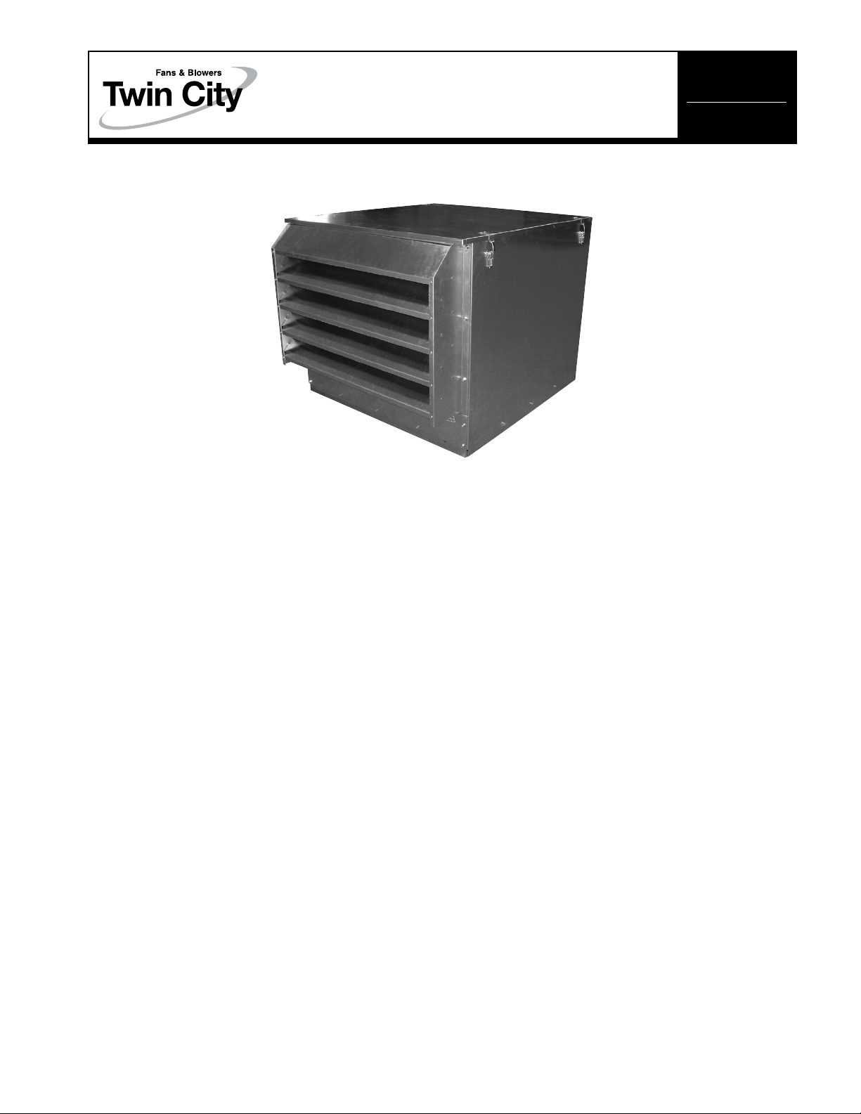
BCFS Belt Driven
Centrifugal Filtered Supply Fans
INSTALLATION, OPERATION & MAINTENANCE MANUAL
Models BCFS 140A through 240A
IM-4300
January 2006
Receiving, Inspection & Unpacking
When the equipment is received all items should be carefully checked against the bill of lading to be sure all crates
and cartons have been received. Before accepting delivery, carefully inspect each carton or crate for visible shipping
damage. If any damage is noticed, the carrier should make the proper notation on the delivery receipt acknowledging
the damage. Make notations of all damage on all copies of the bill of lading and have all copies countersigned by
the delivering carrier. The carrier should also fill out a Carrier Inspection Report. The factory Traffic Department should
then be contacted. File claim for damage with the carrier. Physical damage to the unit after acceptance is not the
responsibility of Twin City Fan Companies, Ltd.
Unpack each carton or crate and verify that all required parts and proper quantities of each item have been received.
Refer to drawings for part descriptions. Report shortages or missing items to your local representative to arrange for
replacement parts.
Due to availability of carriers and truck space, it is not possible to guarantee that all items will be shipped together.
Verification of shipments must be limited to only those items on the bill of lading.
The unit nameplate must be checked to make sure the voltage agrees with the power supply available.
Installation
CAUTION: Sheet metal parts, screws, clips and similar
items inherently have sharp edges, and it is necessary
that the installer and service personnel exercise
caution.
The installation of this equipment shall be in accordance
with the regulations of authorities having jurisdiction and
with all applicable codes.
This equipment is to be installed by an experienced
installation company and fully trained personnel.
The mechanical installation of the exhaust ventilator
consists of making final connections between the unit,
building services, and duct connections.
1. Before setting unit on curb (if damper is to be used),
make sure that the damper is installed correctly and
that it is operative. See diagram, page 6.
2. Position unit on roof curb so that the wiring can be
run through one of the knockouts provided. Wiring to
the unit may be run through knockouts provided in
the curb cap or the side of the unit. Provide enough
slack in the wiring to the unit to allow lifting, and
removal for cleaning, and inspection.
3. Connect supply leads to the disconnect switch.
4. Check line voltage with the motor nameplate and the
attached instruction cards.
5. Determine if wheel is free to rotate and has not been
subject to misalignment in shipping or installation.
6. Apply power and check rotation of wheel with directional label in motor compartment.
7. Lag bolt the unit to the roof curb using a minimum
of four bolts, one at each corner. Replace unit top
panel and fasten all latches securely.
©2006 Twin City Fan Companies, Ltd.
Page 2
Check, Test and Start Procedure
WARNING
Electric shock hazard. Could cause severe injury
or death. Failure to bond the frame of this equipment to the building electrical ground by use of
the grounding terminal provided or other acceptable
means may result in electrical shock. Disconnect
electric power before servicing equipment. Service
to be performed only by qualified personnel.
BEFORE STARTUP: Disconnect power to this unit before
servicing the unit.
1. Check to verify that the wheel is free to rotate.
2. Verify that supply voltage on the line side of disconnect agrees with voltage on unit identification plate and
is within the utilization voltage range as indicated in
Table 1.
3. On three-phase units check and calculate phase
unbalance as follows:
% Voltage Unbalance = 100 x max. voltage deviation
from avg. voltage ÷ avg. voltage
Example: Determine the percent voltage unbalance
given voltages of 220, 216 and 213.
How To Use The Formula:
a. Avg. Voltage = 220 + 216 + 213 = 649 ÷ 3 = 216
b. Max. Voltage Deviation From Avg. Voltage =
220 – 216 = 4
c. % Voltage Unbalance = 100 x (4 ÷ 216) = 1.8%
Voltage unbalance should not exceed 2%.
4. Apply power to unit and check rotation of wheel with
the directional arrow on the unit.
WARNING: The BCFS centrifugal wheels run in a counterclockwise direction when viewed opposite the air
intake. If the wheel is run in the wrong direction, the
motor will overload and burn out.
WARNING: Check three-phase units for rotation. For
three-phase, rotation can be changed by interchanging
any two of the three line leads. If unit is installed on
temporary wiring, it should be rechecked when permanently installed. Motor burn-out or tripped overload
protection devices are usually the result of incorrect
rotation.
WARNING: Motor overloading is usually the result of
incorrect rotation, high voltage, or low voltage. The NEC
states that motors used in devices such as filtered roof
supply units must be protected by a separate overload
device that is responsive to motor current or a thermal
protector integral with the motor. Refer to Sections 43022 of the NEC for additional information.
5. Electrical Input Check: Perform check of fan ampere
draw and verify that motor nameplate amps are not
exceeded. Take account of the service factor range
if motor is nameplated above a 1.0 service factor.
6. Fan RPM Check: Fan RPM should be checked and
verified with a tachometer. Refer to Table 2 for maximum fan RPM values.
WARNING: Running fan at an RPM greater than the
maximum RPM value in Table 2 will overload the fan
motor and lead to premature motor failure.
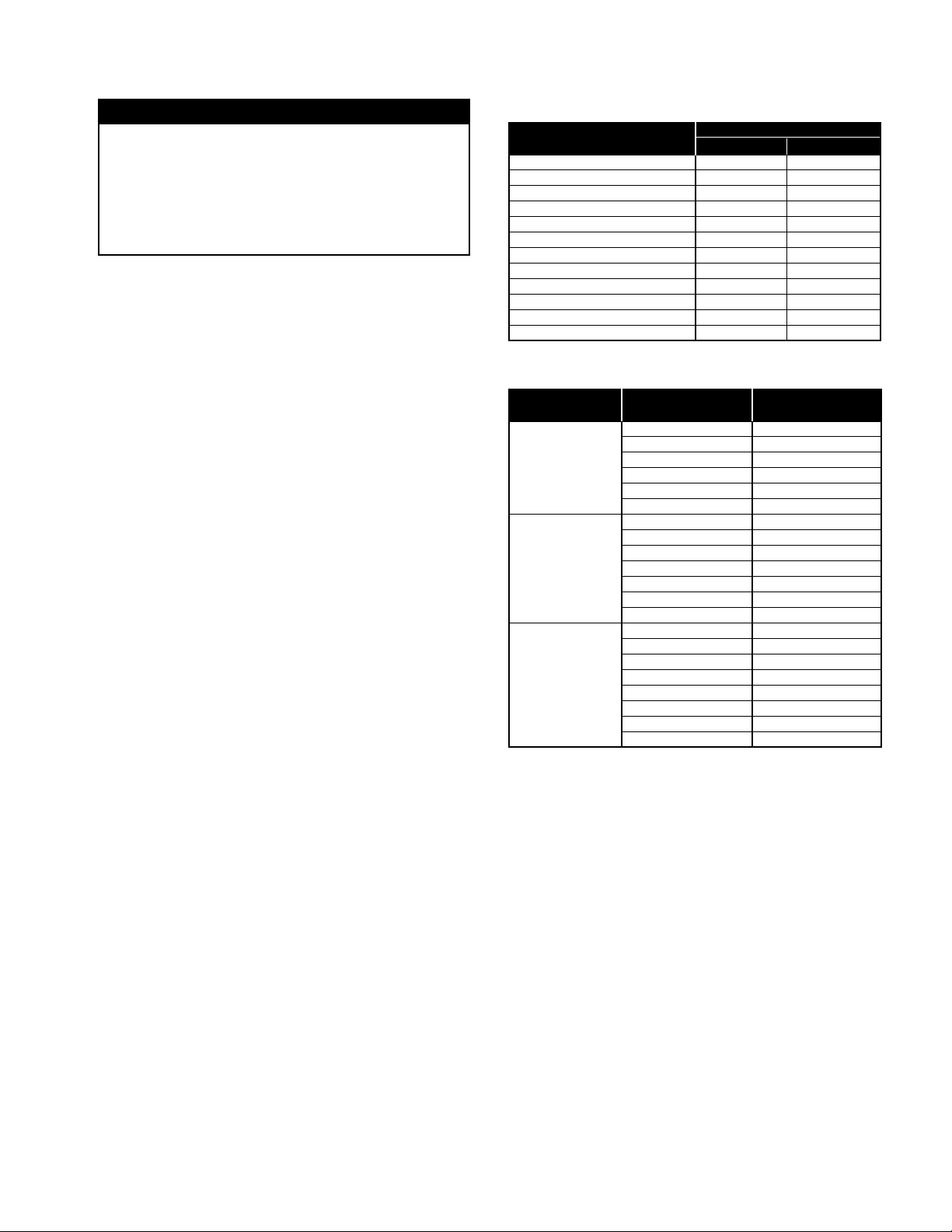
Table 1. Utilization Voltage Ranges
SYSTEM VOLTAGE/ UTILIZATION VOLTAGE
UNIT NAMEPLATE MIN. MAX.
115/60/1 104 127
208-230/60/1 or 208-230/60/3 187 253
230/60/1 or 230/60/3 207 253
277/60/1 249 305
200/60/3 180 220
380/60/3 342 418
460/60/3 414 506
575/60/3 517 633
110/50/1 99 121
220/50/1 198 242
380-415/50/3 342 456
440/50/3 396 484
Table 2. Maximum Fan RPM
BCFS MAXIMUM
MODEL
1/6 1100
1/4 1250
1/2 1590
3/4 1810
1.0 2000
1/6 730
1/4 840
1/3 930
180 1/2 1060
3/4 1220
1.0 1300
1.5 1530
1/3 580
1/2 660
3/4 760
1.5 960
2.0 1060
3.0 1180
5.0 1350
1/3 1380
140
1.0 840
240
MOTOR HP
FAN RPM
Maintenance
FILTERS: To gain access to filters, unlatch top panel
and slide top back approximately 2 inches. Lift filters out
from top. Filters may be cleaned with soap and water
or replaced. Filters should be cleaned regularly, as dirty
filters will cause performance to be reduced. Frequency
of cleaning depends upon the local environment and
frequency of use of the fan.
1. The motors in these units are equipped with prelubricated ball bearings which are considered to be
permanently lubricated.
2. Fan shaft pillow block bearings are equipped with
grease gun fittings. These bearings are factory lubricated and, with normal operation, will need no lubrication for 3 to 6 months.
3. For pillow block bearings, use a low pressure grease
gun with Alvania #2 or #3 grease or equivalent. Only
a few strokes of the gun are required. Excess grease
will be forced out through the bearing pressure relief
holes. Use of a high pressure gun, however, is liable
to blow the bearing seals.
2 Twin City IM-4300
Page 3

4. Belt tension is adjusted at the factory. It should be
readjusted after a break-in period of 24 hours of
actual operation.
5. To adjust belt tension, loosen the hex head screw in
the tab of the motor plate. Snug belts by pulling on
the motor until the belt is tight. Tension is correct if
the belt can be twisted from
1
⁄4 to 1⁄2 turn with mod-
erate pressure at a point midway between sheaves.
6. Belt condition and tension should be checked every
3 to 6 months depending on service. If belt tension
is too tight, there is a possibility of overloading the
motor as well as causing undue belt wear. If the belt
tension is too slack, then the wheel will fall off in
RPM, air delivery will decrease and the belts will wear
quite rapidly.
7. If the air handled by the unit is dust or grease laden,
a regular inspection and cleaning of the backdraft
damper and the wheel will ensure smooth, efficient
operation.
WARNING: Do not replace motor sheave with one larger
in diameter. Do not replace fan sheave with one smaller
in diameter. The sheave ratios are set so that the motor
will not be overloaded within the range of the adjustable sheave.
CHECK: Belt tension is adjusted at the factory, but it
should be readjusted after a break-in period of approximately 24 hours of actual operation.
Figure 2. Opening Location of Duct Adapter AccessoryFigure 1. Typical Installation
Apply foam tape to seal duct
to unit to prevent leakage
Duct Adapter
(Align this side with
inlet side of curb)
L
W
Y
Duct
(Customer
Supplied)
Damper*
X
Figure 3. Location of Fan Outlet
Top View of Roof Curb Showing Duct Location
L
Curb
Sq.
Fan Outlet
Y
Roof
Curb
Nailer
Duct Flange
By Customer
Strip
Position duct adapter as shown and secure to nailer strip
with nails in holes provided in duct adapter.
*For a standard gravity (spring return) damper, recess the
damper a minimum of 2" inside the duct in order to clear the
fan outlet. For an optional motorized damper, the damper must
be recessed 12" to allow for clearance between the actuator
and fan outlet.
MODEL DIMENSION (IN.)
BCFS W L X Y
140A 8
180A 10
240A 13
X
MODEL DIMENSION (IN.) CURB SUPPLY
BCFS W L X Y SQ. DAMPER
140A 8 19 2
W
180A 10 22 2
240A 13
DIMENSIONS ARE NOT TO BE USED FOR CONSTRUCTION.
1
⁄2 191⁄2 2
1
⁄2 221⁄2 1
11
⁄16 291⁄2 1
1
⁄2 71⁄4 30 x 30 8 x 19
1
3
⁄16 29 2 113⁄4 47 x 47 13 x 29
⁄8 91⁄4 36 x 36 10 x 22
1
⁄4 7
7
⁄8 9
3
⁄4 111⁄2
Inlet Side of Fan (Provide a min. of 15"
between inlet side and nearest obstruction)
3 Twin City IM-4300
Page 4

Motor Installation
To prevent damage during shipment, the motor of this
unit has been installed at the factory, tested, then
removed and shipped separately. Please follow the
instructions below to reinstall the motor.
1. Fasten the motor plate to the bearing plate by inserting the hinge pin in the holes and then putting a
hitch pin in the hole of the hinge pin.
See Figure 4.
2. Install the belts on the sheaves, apply tension and
tighten the bolt at the top of the motor plate or the
nut on the jacking bolt to maintain tension. The ideal
Figure 4. Motor Plate Assembly Figure 5. Sheave Alignment
HINGE PIN
TENSION
HOLD BOLT
HITCH PIN
belt tension is to be enough so that the belt does
not slip under peak load. Do not over-tighten the belt
as it will severely reduce the life of the bearings.
3. Check the sheave alignment as shown in Figure 5
below and align sheaves with a straightedge if necessary. Be sure the belt tension is rechecked if the
sheave alignment is changed.
Note: The belt tension will need to be rechecked after
the fan has been operating for a few days. There is an
initial break-in period for the belts in which they may
stretch.
Limitation of Warranties and Claims
Seller warrants to the original purchaser that the goods
sold hereunder shall be free from defects in workmanship and material under normal use and service (except
in those cases where the materials are supplied by the
buyer) for a period of one year from the date of original
installation or eighteen (18) months from the date of shipment, whichever occurs first. The liability of seller under
this warranty is limited to replacing, repairing, or issuing
credit (at cost, F.O.B. factory and at seller’s discretion)
for any part or parts which are returned by buyer during
such period provided that:
a. seller is notified in writing within ten (10) days follow-
ing discovery of such defects by buyer, or within ten
(10) days after such defects should reasonably have
been discovered, whichever is less;
b. the defective unit is returned to seller, transportation
charges prepaid by buyer.
c. payment in full has been received by seller for said
products; and
d. seller’s examination of such unit shall disclose to its
satisfaction that such defects have not been caused
by misuse, neglect, improper installation, repair,
alteration, act of God, or accident.
No warranty made hereunder shall extend to any seller
product whose serial number is altered, effaced or
removed. Seller makes no warranty, express or implied,
with respect to motors, switches, controls, or other
components of seller’s product, where such components
are warranted separately by their respective manufacturers. THIS WARRANTY IS EXPRESSLY IN LIEU OF ALL
OTHER WARRANTIES, EXPRESS OR IMPLIED, WHETHER
STATUTORY OR OTHERWISE, INCLUDING ANY IMPLIED
WARRANTY OF MERCHANTABILITY OR FITNESS FOR A
PARTICULAR PURPOSE. In no event shall seller be liable
to buyer for indirect, incidental collateral, or consequential
damages of any kind. (BUYER’S FAILURE TO PAY THE
FULL AMOUNT DUE WITHIN SIXTY (60) DAYS OF DATE
OF INVOICE SHALL OPERATE TO RELEASE SELLER
FROM ANY AND ALL LIABILITY OR OBLIGATION ARISING
PURSUANT TO ANY WARRANTY, EXPRESS OR IMPLIED,
WHETHER STATUTORY OR OTHERWISE, INCLUDING
ANY IMPLIED WARRANTY OR MERCHANTABILITY
OR FITNESS FOR A PARTICULAR PURPOSE, MADE
IN CONNECTION WITH ANY CONTRACT FORMED
HEREUNDER. BUYER AGREES THAT SUCH FAILURE TO
PAY SHALL CONSTITUTE A VOLUNTARY WAIVER OF
ANY AND ALL SUCH WARRANTIES ARISING PURSUANT
TO SUCH CONTACT.)
Twin ciTy fan & blower | www.Tcf.com
5959 Trenton Lane N | Minneapolis, MN 55442 | Phone: 763-551-7600 | Fax: 763-551-7601
1MPP11/09
 Loading...