

Page 1

Axial Roof Ventilators
& Tubeaxial Fans
INSTALLATION, OPERATION & MAINTENANCE MANUAL
Models: TB, TBSH, TD, TUB, TUBSH, TUD
Twin City Fan & Blower Catalogs 4830 and 4850 provide
additional information on this equipment. These catalogs
can be found at www.tcf.com or by contacting your
Introduction
DO NOT INSTALL, USE OR OPERATE THIS EQUIPMENT
UNTIL THIS MANUAL HAS BEEN READ AND
UNDERSTOOD. READ AND SAVE THESE INSTRUCTIONS
FOR FUTURE USE.
The purpose of this manual is to aid in the proper
installation and operation of fans supplied by Twin City
Fan & Blower. These instructions are intended to supplement good general practices and are not intended to
cover detailed instruction procedures because of the
IM-4000
August 2014
local Twin City Fan & Blower sales representative. Also
see installation and maintenance manuals ES-191 and
ES-404.
wide variety and types of fans manufactured by Twin
City Fan & Blower.
It is the responsibility of the purchaser to assure that
the installation and maintenance of this equipment is
handled by qualified personnel experienced in such work
and equipment.
Contact your local representative should you need further information.
Shipment and Receiving
Prior to shipment, all fans have been thoroughly inspected and tested.
All equipment shipped from Twin City Fan & Blower is
boxed or crated to fully comply with trucking requirements. Inspect all shipments carefully for damage.
THE RECEIVER MUST NOTE ANY DAMAGE ON THE
CARRIER’S BILL OF LADING AND FILE A CLAIM
Handling
Handle your equipment with caution. Some fans are provided with lifting lugs or holes for easy handling. Others
must be handled using nylon straps which protect the
fan’s coating and housing. Spreader bars should be
used when lifting large parts.
Fans should be lifted by using straps around the fan
housing only. DO NOT LIFT FANS BY THE MOTOR,
MOTOR BASE, PROP OR FLANGES.
Storage
If fans are stored for any length of time, they should
be stored in a clean, dry location to prevent rust and
corrosion. Outdoor storage is not recommended. When
outdoor storage is necessary, fans should be protected
from the elements as completely as possible. Cover the
fan inlet and outlet and keep motors dry and clean.
For extended storage (more than 3 months) motor shafts
and bearings should be rotated monthly. If stored longer
IMMEDIATELY WITH THE FREIGHT COMPANY IN THE
CASE OF ANY DAMAGE. Keep a record of all equipment received including inspection details and date of
receipt due to the possibility of partial shipments.
If you receive damaged goods, contact your sales or
factory representative for repair or replacement service.
Roof ventilators should be lifted by using straps around
the fan housing or base only. Spreader bars should also
be used to avoid damage to stack caps or hoods. DO
NOT LIFT ROOF VENTILATORS BY THE STACK CAP
OR HOOD. On hooded units, disassemble the stack
from hood when lifting. Upblast models may be lifted
assembled.
than 6 months, bearing grease in motor and fan should
be purged and replaced with compatible grease. Belts
should be rechecked for proper tension. Storage records
should be kept to assure proper maintenance. The factory can advise warranty centers to provide motor and
bearing service if needed.
©2014 Twin City Fan Companies, Ltd.
Page 2
Installation
Roof ventilators should always be mounted to a flat,
level, solid and rigid structure. Particular caution should
be exercised when installing fans on metal buildings. Be
sure wall or roof is capable of supporting the fan(s).
Fans mounted on walls or roofs and not supported
correctly will cause vibration that could cause damage
or injury.
Fans mounted off ground level should be rigidly mounted to a structural platform and be placed over or as
near as possible to a solid wall or column.
Support for suspended fans must be cross-braced for
live load support to prevent side sway.
Use guy wires to help secure roof units if excessively
windy conditions prevail.
1. CAUTION! This fan contains rotating parts and
requires electrical service. Appropriate safety precautions should be taken during installation, operation
and maintenance.
2. WARNING! Do not install or operate this fan in an
environment or atmosphere where combustible or
flammable materials, gasses or fumes are present
unless it was specifically designed and manufactured for use in that environment. Explosion or fire
can result. Explosive, corrosive, high temperature,
or other extreme conditions may require special
construction, inspection and maintenance. It is
necessary to observe the fan manufacturer’s recommendations and limitations concerning the type of
material to be handled by the fan and its application
to special conditions.
3. When the roof ventilator is designed to be mounted
on a curb, the curb should be securely installed
prior to fan installation.
4. A damper, if used, should be securely mounted
within the curb or wall in a manner which allows
free and unobstructed operation.
5. CAUTION! All electrical work must be done in accordance with local and/or national electrical codes as
applicable. If you are unfamiliar with methods of
installing electrical wiring, secure the services of a
qualified electrician.
6. WARNING! This product must be grounded.
7. DANGER! Make sure power is turned off and locked
in the OFF position at the service entrance before
installing, wiring or servicing fan.
8. CAUTION! Before wiring the motor, check the supply voltage against the motor nameplate voltage.
High or low voltage can damage the motor and void
the motor warranty. See Table 1.
Table 1. Utilization Voltages
SYSTEM VOLTAGE/ UTILIZATION VOLTAGE
UNIT NAMEPLATE MIN. MAX.
115/60/1 104 127
208-230/60/1 or 208-230/60/3 187 253
230/60/1 or 230/60/3 207 253
277/60/1 249 305
200/60/3 180 220
380/60/3 342 418
460/60/3 414 506
575/60/3 517 633
110/50/1 99 121
220/50/1 198 242
380-415/50/3 342 456
440/50/3 396 484
9. On three-phase units check and calculate phase
unbalance as follows:
% Voltage Unbalance = 100 x max. voltage deviation
from avg. voltage ÷ avg. voltage
How To Use The Formula:
With voltage of 220, 216 and 213
a. Avg. Voltage = 220 + 216 + 213 = 649 ÷ 3 = 216
b. Max. Voltage Deviation From Avg. Voltage =
220 – 216 = 4
c. % Voltage Unbalance = 100 x (4 ÷ 216) = 1.8%
Voltage unbalance should not exceed 2%.
10. WARNING! Be sure to keep all wiring clear of rotat-
ing or moving parts.
11. WARNING! Before starting the fan, turn the wheel to
assure it rotates freely. If needed, adjust the wheel/
shaft/bearing/motor position as required to achieve
necessary clearances.
12. On belt driven units, assure belts are tensioned and
aligned properly. See Maintenance section, page 3.
13. Check all setscrews and keys. Tighten as necessary
prior to fan start-up.
14. On roof units, anchor the fan securely to the curb.
Anchoring through the vertical portion of the curb
cap flange is recommended. Use a minimum of four
lag bolts or other suitable fasteners.
15. As with most installations of rotating machinery,
due to the nature of their applications, most fans
are available with protective guards and/or other
devices for required operating safety. Before operating the unit in any of its applications, determine the
requirements for any guards and/or devices needed
for protection against accidental contact with moving parts or against injury to nearby personnel or
equipment due to accidental rupture of fast moving
parts.
Check, Test & Start Procedure
WARNING
Electric shock hazard. Could cause severe injury or
death. Failure to bond the frame of this equipment
to the building electrical ground by use of the
grounding terminal provided or other acceptable
means may result in electrical shock. Disconnect
electric power before servicing equipment. Service
to be performed only by qualified personnel.
2 Twin City IM-4000
BEFORE START-UP: Disconnect power to this unit
before servicing the unit.
1. Check to verify that the propeller is free to rotate.
2. Verify that supply voltage on the line side of discon-
nect agrees with voltage on fan data plate and is
within the 10% utilization voltage.
3. Apply power to unit and check rotation of propeller
with the directional arrow on the unit.
WARNING: Rotation is critical. If allowed to operate
in the wrong direction, the motor will overload and
burn out.
Page 3

WARNING: Check units for rotation. For three-phase,
rotation can be changed by interchanging any two of
the three line leads. If unit is checked on temporary
wiring, it should be rechecked when permanently
installed. Motor burn-out or tripped overload protection devices are usually the result of wrong rotation.
4. Electrical Input Check: Perform check of fan ampere
draw and verify that motor nameplate amps are not
exceeded. Take into account the service factor range
if motor is nameplated above a 1.0 service factor.
Maintenance
1. Before performing any maintenance on the fan, be
sure power is turned off and locked in the OFF
position at the service entrance.
2. Ventilators should be carefully checked at least once
a year. For critical or rugged applications, a routine
check every two or three months is suggested.
3. All motors supplied with Twin City Fan & Blower
ventilators carry a one-year limited warranty from
date of shipment. For repairs within the warranty
period, the motor must be taken to the motor
manufacturer’s authorized service dealer. Contact
your representative for additional warranty details.
4. A periodic motor check should consist of spinning
the motor shaft with the power off to be sure the
motor turns freely and the bearings run smoothly.
The belt on belt driven units should be removed
from the motor sheave.
5. When removing or installing a belt, do not force
the belt over the sheave. Loosen the motor mount
so that the belt can be easily slipped over the
sheave.
6. The belt on belt driven units should be removed and
carefully checked for glazing, cracks, ply separation
or irregular wear. A small irregularity in the contact
surface of the belt will result in noisy operation. If
any of these defects are apparent, the belt should
be replaced. Check the sheaves also for chipping,
dents or rough surfaces which could damage the
belt.
7. The correct belt tension is important. Too tight of
a belt will result in excess bearing pressure on the
motor bearings and shaft pillow blocks and may
also overload the motor. Too loose of a belt will
result in slippage which will quickly “burn” out belts.
A belt should feel “live” when thumped, approximately
to finger pressure at midpoint between sheaves.
8. The belt alignment should also be checked to be
sure the belt is running perpendicularly to the rotating shafts. Fan and motor shafts must be parallel. Improper alignment will result in excessive belt
wear.
9. Check sheave setscrews to ensure tightness. Proper
keys must be in keyways.
10. Do not readjust blade pitch or fan RPM. If sheaves
are replaced, use only sheaves of identical size and
type.
1
⁄4" belt deflection (3 to 5 lb.) when subject
5. Fan RPM should be checked and verified with a
tachometer.
NOTE: The fan was balanced at the factory to be
within stringent vibration levels before shipment.
However, there are several things that may cause
vibration, such as rough handling in shipment and
installation, weak foundations and alignments.
11. If unit is to be left idle for an extended period, it is
recommended that belts be removed and stored in
a cool, dry place to avoid premature belt failure.
12. The standard pillow block bearings on belt driven
ventilators are factory lubricated and are provided with
external grease fittings. Annual relubrication is recommended, or more frequently if needed (see Table 2).
Do not over-grease. Use only 2 or 3 shots of
a recommended lubricant with a hand gun in most
cases (see Table 3). Maximum hand gun rating 40
P.S.I. Rotate bearings during lubrication where good
safety practice permits.
CAUTION: Greases of different soap bases
(lithium, sodium, etc.) may not be compatible when
mixed. Prevent such intermixing by completely purging the bearing of old greases.
The most frequent causes of bearing failure are
not greasing often enough, using an excessive
quantity of grease, or using incompatible greases.
Excessive vibration, especially if the bearing is not
rotating, will also cause bearings to fail. Bearings
must also be protected from water and moisture to
avoid internal corrosion.
13. During the first few months of operation it is rec-
ommended that the bearing setscrews be checked
periodically to ensure that they are tight.
14. The rotating wheel or propeller requires particular
attention since materials in the air being handled
can build up on the blades to cause destructive
vibration or weaken the structure of the propeller by corroding and/or eroding the blade metal.
Regular inspection and corrective action at intervals
determined by the severity of each application are
essential to good service life and safety.
Table 2. Suggested Fan Bearing Greasing Intervals
INTERVAL
(MONTHS)
12 to 18 Infrequent operation or light duty in clean atmosphere.
6 to 12 8 to 16 hrs./day in clean, relatively dry atmosphere.
3 to 6 12 to 24 hrs./day, heavy duty, or if moisture is present.
temperatures; moisture laden atmosphere; vibration.
Heavy duty in dirty, dusty locations; high ambient
1 to 3
TYPE OF SERVICE
Table 3. Grease Manufacturers
MANUFACTURER GREASE (NLGI #2)
Shell Gadus S2 V100 2
Exxon/Mobil Ronex MP
Twin City IM-4000 3
Page 4
V-Belts
V-belts on these belt driven fans are oil, heat, and static
resistant type and oversized for continuous duty. With
proper installation and maintenance, years of operating
efficiency can be added to the lifespan of the V-belt
drive.
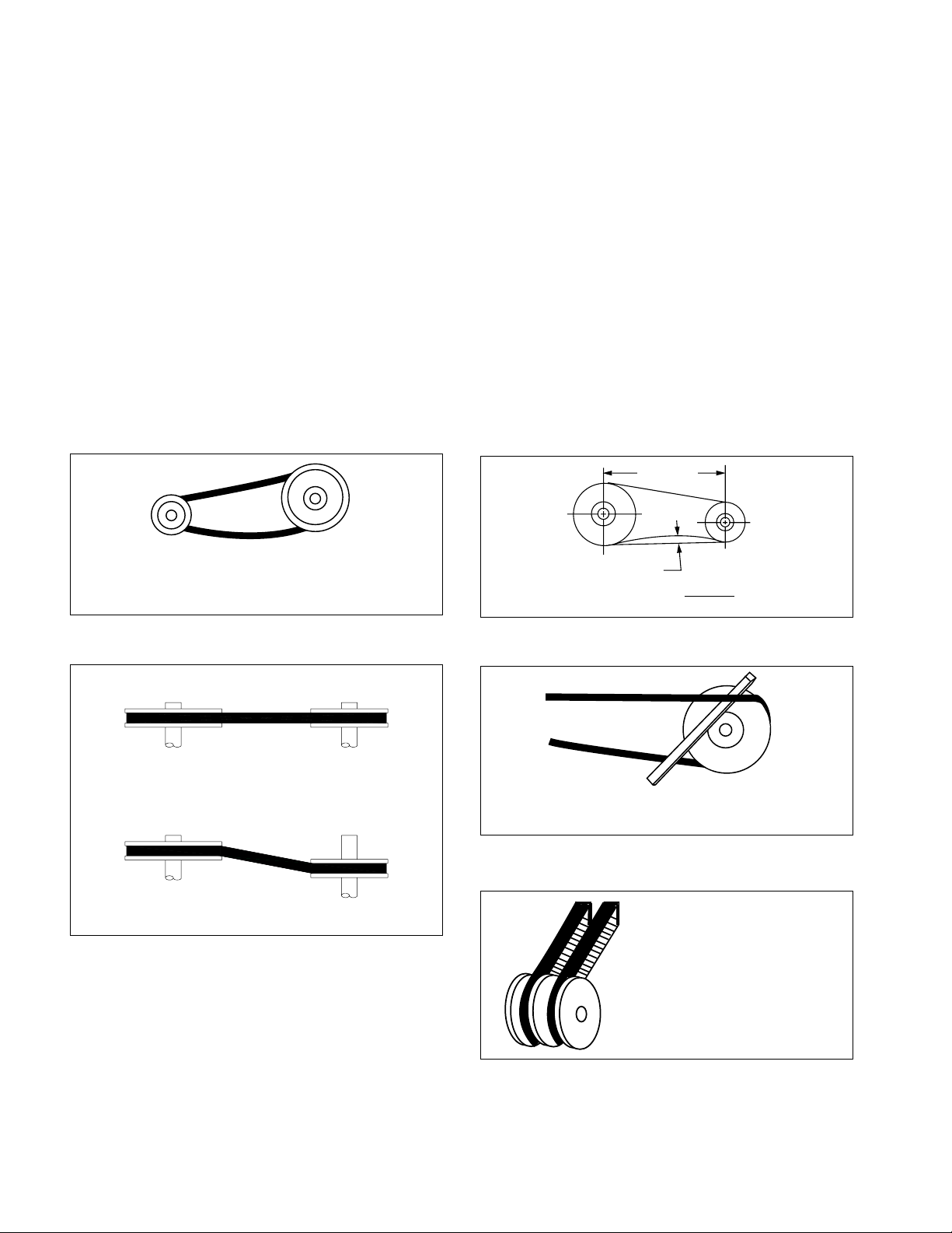
The condition of V-belts and the amount of belt tension
should be checked prior to start-up (see Figure 1). When
it becomes necessary to adjust belt tension, do not overtension as bearing damage will occur. Recommended
belt tension should permit
span of the belt at the center of the belt span. To
find this point, measure halfway between the pulley
centerlines as shown in Figure 2. Extreme care must be
exercised when adjusting V-belts as not to misalign the
pulleys. Any misalignment will cause a sharp reduction
in belt life and will also produce squeaky, annoying
noises (see Figure 3). On units equipped with 2 groove
pulleys, adjustments must be made so that there is
equal tension on all belts (see Figure 5).
Figure 1. Eliminate Slack Figure 2. Belt Deflection
1
⁄64" deflection per inch of
1. Where tensioning rods are not available, adjustment is
more easily obtained by loosening and adjusting one
side of the motor bracket at a time.
2. Always loosen tension adjustment enough to place
belts on sheaves without running belts over the
edge of either sheave. A new belt may be seriously
damaged internally by careless handling (see Figure
4).
WARNING: When removing or installing belts, never
force belts over pulleys without loosening motor first to
relieve belt tension.
3. Fan speed can be increased by closing the adjustable
motor pulley, or decreased by opening it. Two
and three groove adjustable pitch pulleys must be
adjusted an equal number of turns. (See Figure 5).
Always check load on motor when increasing fan
speed.
Belt Span
Slack belts wear excessively, cause slippage
and deliver less power. For longest belt life,
always provide proper tension
Figure 3. Alignment Figure 4. Belts
CORRECT
Do not force belt. Forcing the belt will
break the cords and cause belt failure.
Figure 5. 2-Groove Sheaves
INCORRECT
Mount belts straight. Shafts must be parallel
and sheaves in alignment to prevent unnecessary belt wear.
Deflection
Deflection =
64
Belt Span
Two-groove variable pitch
sheaves must be opened the
same number of turns on
both sides; otherwise, slippage occurs, wearing belts
rapidly,
4 Twin City IM-4000
Page 5

Bearing Replacement
Fan bearings on belt driven fans should not need to be
replaced for many years if the previous recommendations are strictly adhered to. However, use the following
procedure when bearing replacement is necessary.
1. Gain access to the fan bearings. Remove the bearing cover, if any.
2. Loosen the belts by shifting the motor.
3. Remove the propeller or wheel and disconnect the
remote lube lines (if applicable).
4. Measure the location of the bearing to the propeller
or wheel end of the shaft and the bearing spacing.
5. Remove the shaft and bearing assembly. Note the
position of the bearings’ shims (if applicable).
6. Loosen all bearing/shaft setscrews or other locking
devices.
7. Remove bearings (may need to be pressed off the
shaft).
8. Polish the shaft with fine emery paper (240 grit or
finer) and file the setscrew dimples left on the shaft
flat.
9. Install new bearings on the shaft, making sure that
the collars are together (i.e. facing each other on the
shaft). Lightly seat one setscrew or eccentric locking
collar on each bearing to hold in the approximate
marked position.
10. Mount the shaft/bearing assembly in the fan with
bolts. Do not tighten yet. Just snug up. Loosen the
setscrew.
11. Center the shaft in the housing (both ends) as
closely as possible. (The fan propeller or wheel may
need to be temporarily installed to get its clearances
equal.)
12. Lubricate bearings. See Table 3, Page 3.
13. Tighten setscrews in steps (alternating half turns).
Note torquing requirements with bearing instructions.
14. Tighten the bearing mounting bolts.
15. Reinstall the lube lines (if applicable).
16. Install bearing cover, propeller and belts and adjust
the motor to get proper belt tension. Also, make
sure that the sheaves are properly aligned.
17. If a new shaft is supplied, ignore items 6 thru 8.
Motors
Twin City Fan & Blower recommends periodic checks
of voltage, frequency and current of a motor while in
operation. Such checks assure the correctness of frequency and voltage applied to the motor, and yield an
indication of the fan load. Comparison of this data with
previous data will give an indication of the fan performance. Any serious deviations could indicate a potential
motor failure.
All motors have prelubricated sealed bearings and are
lubricated for the life of the motor.
1. All motors carry a one-year limited warranty from date
of shipment. For repairs within the warranty period,
the motor must be taken to the motor manufacturer’s
authorized service dealer. Contact your representative
for additional warranty details.
2. A periodic motor check should consist of spinning
the motor shaft with the power off to be sure the
motor turns freely and the bearings run smoothly. The
belt on belt driven units should be removed from the
motor pulley.
Repair or replacement of motors is normally performed
by a repair station authorized by the manufacturer.
Contact your representative or the factory for locations
nearest you. DO NOT ship motor to the factory without
specific authorization forms.
Twin City IM-4000 5
Page 6

Fan Troubleshooting Chart
PROBLEM POSSIBLE CAUSES
FAN DOES NOT OPERATE 1. Wrong voltage.
2. Electricity turned off or not wired properly.
3. Tripped overload protector.
4. Blown fuses.
5. Loose pulleys.
6. Broken belts.
TOO LITTLE AIR 1. Wheel or propeller rotating in wrong direction.
2. Fan speed lower than design.
3. System is more restrictive (more static pressure) than expected.
4. Restricted fan inlet or outlet.
5. Inlet or outlet screens clogged.
6. Filters, if applicable, are dirty or clogged.
TOO MUCH AIR 1. Fan speed higher than design.
2. System is less restrictive (less static pressure) than expected.
3. Filters, if applicable, not in place.
EXCESSIVE HORSEPOWER 1. Wheel or propeller rotating in wrong direction.
2. Wheel or propeller rubbing on inlet venturi.
3. Fan speed higher than design.
4. Worn fan bearings.
EXCESSIVE NOISE 1. Wheel, propeller or sheaves loose.
2. Bearing or drive misalignment.
3. Accumulation of material on wheel or propeller.
4. Worn or corroded wheel or propeller.
5. Wheel or propeller out of balance.
6. Wheel or propeller hitting housing.
7. Bent shaft.
8. Bearings need lubrication.
9. Loose bearing bolts.
10. Loose or worn bearings.
11. Mismatched belts.
12. Belts too loose or too tight.
13. Belts oily or dirty.
14. Belts worn.
15. Loose fan mounting bolts.
16. Rattle of components in high velocity airstream.
17. Electrical noise.
18. Noise from high velocity air system.
19. Vibrating parts not isolated from building.
20. Vibrating ductwork.
EXCESSIVE VIBRATION 1. Wheel, propeller or sheaves loose on shaft.
2. Wheel or propeller out of balance.
3. Excessive buildup of dirt/dust on wheel or propeller.
4. Belts too loose or too tight.
5. Mismatched belts.
6. Bent shaft.
7. Bearing or drive misalignment.
8. Loose or worn bearings.
9. Fan mounting bolts loose.
10. Weak mounting base for fan.
11. Structures not cross-braced.
12. Curb not flat and level.
It is recommended that the users and installers of this shipment familiarize themselves with AMCA Publication #201,
“Fans and Systems” and publication #202, “Troubleshooting” which are published by the Air Movement and Control
Association (AMCA), 30 West University Drive, Arlington Heights, Illinois 60004. www.amca.org
6 Twin City IM-4000
Page 7

Limitation of Warranties and Claims
Seller warrants to the original purchaser that the
goods sold hereunder shall be free from defects in
workmanship and material under normal use and service
(except in those cases where the materials are supplied
by the buyer) for a period of one year from the date of
original installation or eighteen (18) months from the date
of shipment, whichever occurs first. The liability of seller
under this warranty is limited to replacing, repairing, or
issuing credit (at cost, F.O.B. factory and at seller’s
discretion) for any part or parts which are returned by
buyer during such period provided that:
a. seller is notified in writing within ten (10) days
following discovery of such defects by buyer, or
within ten (10) days after such defects should
reasonably have been discovered, whichever is less;
b. the defective unit is returned to seller, transportation
charges prepaid by buyer;
c. payment in full has been received by seller for said
products;
d. seller’s examination of such unit shall disclose to its
satisfaction that such defects have not been caused
by misuse, neglect, improper installation, repair,
alteration, act of God, or accident.
No warranty made hereunder shall extend to any
seller product whose serial number is altered, effaced
or removed. Seller makes no warranty, express or
implied, with respect to motors, switches, controls,
or other components of seller’s product, where such
components are warranted separately by their respective
manufacturers. THIS WARRANTY IS EXPRESSLY IN LIEU
OF ALL OTHER WARRANTIES, EXPRESS OR IMPLIED,
WHETHER STATUTORY OR OTHERWISE, INCLUDING
ANY IMPLIED WARRANTY OF MERCHANTABILITY OR
FITNESS FOR A PARTICULAR PURPOSE. In no event
shall seller be liable to buyer for indirect, incidental
collateral, or consequential damages of any kind.
(BUYER’S FAILURE TO PAY THE FULL AMOUNT DUE
WITHIN SIXTY (60) DAYS OF DATE OF INVOICE SHALL
OPERATE TO RELEASE SELLER FROM ANY AND ALL
LIABILITY OR OBLIGATION ARISING PURSUANT TO
ANY WARRANTY, EXPRESS OR IMPLIED, WHETHER
STATUTORY OR OTHERWISE, INCLUDING ANY IMPLIED
WARRANTY OR MERCHANTABILITY OR FITNESS FOR
A PARTICULAR PURPOSE, MADE IN CONNECTION
WITH ANY CONTRACT FORMED HEREUNDER. BUYER
AGREES THAT SUCH FAILURE TO PAY SHALL
CONSTITUTE A VOLUNTARY WAIVER OF ANY AND ALL
SUCH WARRANTIES ARISING PURSUANT TO SUCH
CONTACT.)
Twin City IM-4000 7
Page 8

TWIN CITY FAN & BLOWER | WWW.TCF.COM
5959 Trenton Lane N | Minneapolis, MN 55442 | Phone: 763-551-7600 | Fax: 763-551-7601
7.5MWG8/11
 Loading...