

Page 1
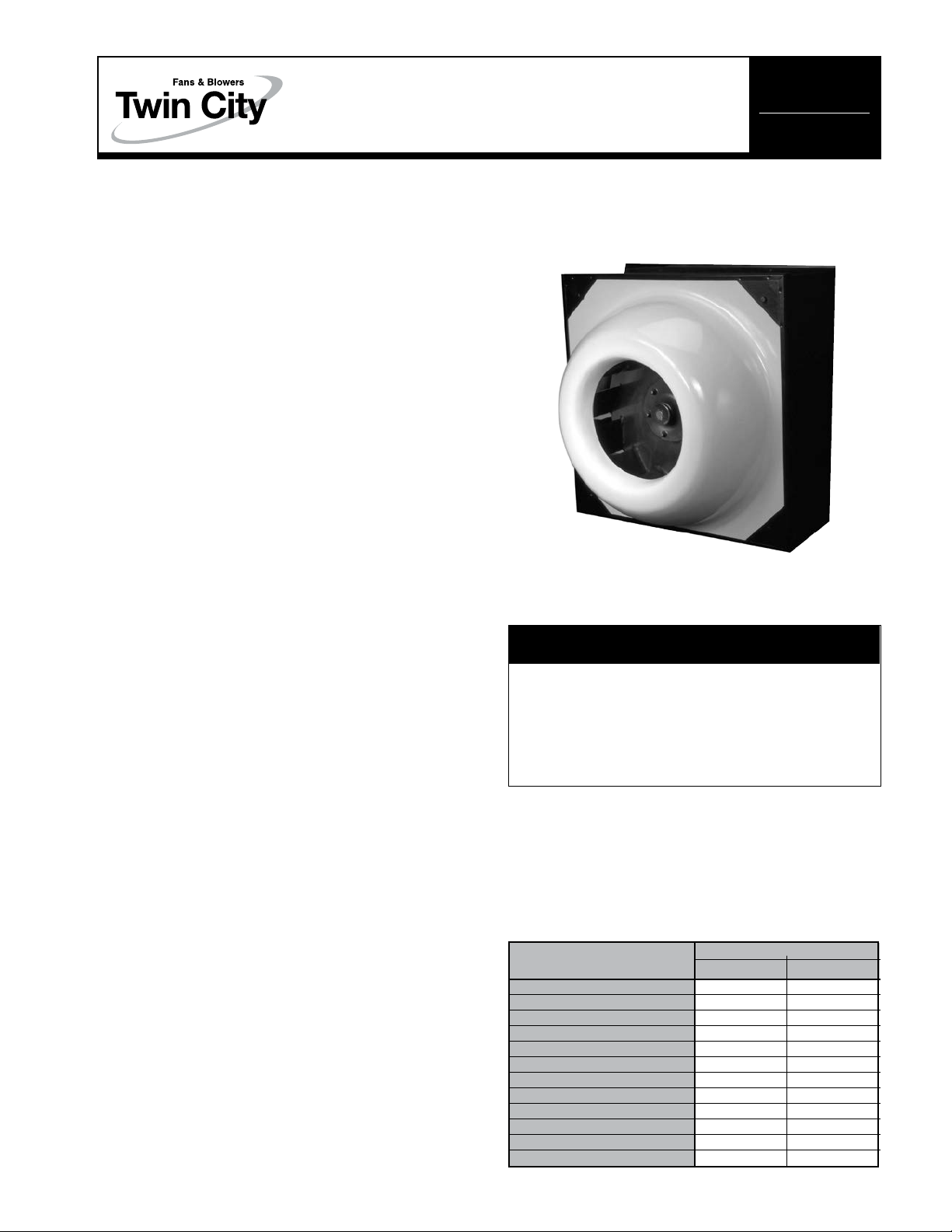
HA/HAB Fiberglass
Wall Mount Ventilators
INSTALLATION, OPERATION & MAINTENANCE MANUAL
Receiving
The HA/HAB ventilator is shipped in two parts:
1. Fan housing assembly complete with fiberglass inlet
venturi to the wheel and complete motor and drive
assembly.
2. Flanged extruded aluminum louver assembly.
Duct adapter and companion angles are shipped loose
if unit is for inline application.
Inspect cartons or crates carefully before signing a delivery receipt for the carrier. If any damage is apparent,
note it on the carrier’s receipt so that a claim can be
filed against the carrier through your usual channels.
Handle the units carefully while delivering to installation
location. Use ordinary care in unpacking the units. If the
units, when unpacked, appear to be damaged in a way
that could not be determined at the time of delivery,
notify the carrier that concealed damage has been discovered and insist on inspection by the carrier. Obtain
a copy of carrier’s inspection report showing the concealed damages so that a claim can be filed through
your usual channels.
Study the attached installation prints carefully. Inspect
the units carefully for identification marks, fan rotation
symbols, etc.
IM-3100
August 2014
Check, Test & Start Procedure
WARNING
Installation
Wall Application
1. Remove wood shipping supports from fan assembly
(see Figure 1).
1
2. Locate and provide hole in the wall
the fan housing (see Figure 2). This will provide an
opening for the electrical wiring into the unit.
3. Anchor the box in the wall, keeping a minimum of
23⁄8" between the outside wall and any part of the
box or the power assembly.
4. Fasten the flanged extruded louver to the exterior
wall.
Inline Application
1. Remove wood shipping supports from fan assembly
(see Figure 1).
2. Attach duct adapter and companion angles to unit
per Figure 3 with fasteners supplied.
3. Before anchoring the unit to the ductwork, check line
voltage and current characteristics outlined in previous section.
4. Fasten the flanged extruded louver to the exterior wall
wherever the outlet of the ductwork ends.
For easy maintenance of the ventilator inline, provide a
drop-out section between ductwork and duct adapter
(see Figure 3).
⁄2" larger than
©1997 Twin City Fan Companies, Ltd.
Electric shock hazard. Could cause severe injury or
death. Failure to bond the frame of this equipment
to the building electrical ground by use of the
grounding terminal provided or other acceptable
means may result in electrical shock. Disconnect
electric power before servicing equipment. Service to
be performed only by qualified personnel.
BEFORE START-UP: Disconnect power to this unit
before servicing the unit.
1. Check to verify that the wheel is free to rotate.
2. Verify that supply voltage on the line side of disconnect agrees with voltage on unit identification plate
and is within the utilization voltage range as indicated
in Table 1.
Table 1.
SYSTEM VOLTAGE/
UNIT NAMEPLATE MIN. MAX.
115/60/1 104 127
208-230/60/1 or 208-230/60/3 187 253
230/60/1 or 230/60/3 207 253
277/60/1 249 305
200/60/3 180 220
380/60/3 342 418
460/60/3 414 506
575/60/3 517 633
110/50/1 99 121
220/50/1 198 242
380-415/50/3 342 456
440/50/3 396 484
UTILIZATION VOLTAGE
Page 2
3. On three-phase units check and calculate phase unbalance as follows:
% Voltage Unbalance = 100 x max. voltage deviation
from avg. voltage ÷ avg. voltage
Given example: With voltage of 220, 216 and 213
How To Use The Formula:
a. Avg. Voltage = 220 + 216 + 213 = 649 ÷ 3 =
216
b. Max. Voltage Deviation From Avg. Voltage =
220 – 216 = 4
c. % Voltage Unbalance = 100 x (4 ÷ 216) = 1.8%
Voltage unbalance should not exceed 2%.
4. Apply power to unit and check rotation of wheel with
the directional arrow on the unit.
WARNING: Especially check three-phase units for rota-
tion. For three-phase, rotation can be changed by
interchanging any two of the three line leads. If unit is
check on temporary wiring, it should be rechecked
when permanently installed. Motor burn-out or tripped
overload protection devices are usually the result of
wrong rotation.
5. Electrical Input Check: Perform check of fan ampere
draw and verify that motor nameplate amps are not
exceeded. Take account of the service factory range
if motor is nameplated above a 1.0 service factor.
6. Fan RPM Check: Fan RPM should be checked and
verified with a tachometer. Refer to Table 2 for maximum fan RPM values.
WARNING: Running fan at an RPM greater than the
maximum RPM value in Table 2 will overload the fan
motor and lead to premature motor failure.
Table 2. Maximum Fan RPM (Belt Drive Units)
MAXIMUM
MODEL
12HA1B, 2B, 3B 1/4 1740
14HA1B, 2B, 3B 1/4 1470
14HA4B 1/3 1615
14HA5B 1/2 1850
18HA1B, 2B 1/4 945
18HA3B 1/3 1040
18HA4B 1/2 1200
18HA5B 3/4 1365
24HA1B 1/4 575
24HA2B 1/3 633
24HA3B 1/2 725
24HA4B 3/4 830
24HA5B 1 915
30HA1B 1/3 440
30HA2B 1/2 500
30HA3B 3/4 575
30HA4B 1 630
30HA5B 1
30HA6B 2 795
MOTOR HP
FAN RPM
1
⁄2 725
Table 3. Bearing Lubrication Interval
(Belt Drive Model HAB Only)
OPERATING CONDITION GREASING INTERVAL
FAIRLY CLEAN 6 TO 12 MONTHS
MODERATE TO
EXTREMELY DIRTY 1 MONTH
1. Frequency or regreasing will vary, depending on the hours of
operation, temperature and surrounding conditions.
2. Bearings have been prelubricated from factory with NLGI Grade
No. 2 lithium-12 hydroxysterate base grease.
Belts on belt-drive units should be readjusted after 24
hours of operation. Loosen motor base bolts and apply
15 lbs. pull per belt for proper belt tensions. Tighten
motor base bolts.
Check contact surfaces of belt for excessive wear. If
belts have a slick, glazed look or are cracked, belts are
slipping. Replace belts as required.
Motors require no lubrication for 10 years of normal
operation.
The inlet venturi is molded shock-resistant, bonded,
reinforced fiberglass and will require no maintenance.
Wall Application
1. Servicing or inspecting the unit can be accomplished
from the exterior by removing the flanged extruded
louver and from the interior of the building by removing the fiberglass inlet (see Figure 2).
2. To remove the motor assembly for servicing, unplug
the motor from the provided outlet and unfasten the
four vibro-isolator bolts. The entire motor assembly,
including the wheel and bearing (belt drive units), will
slide out of the housing.
Inline Application
For easy maintenance of the inlet unit, provide a dropout section between the ductwork and duct adapter (see
Figure 3).
Servicing or inspection can then be accomplished by
removing the dropout section, then removing the fiberglass inlet. The motor assembly can then be removed
by disconnecting the motor from the provided outlet and
unfastening the four vibro-isolator bolts. Periodic inspection and cleaning of the fan will insure smooth operation.
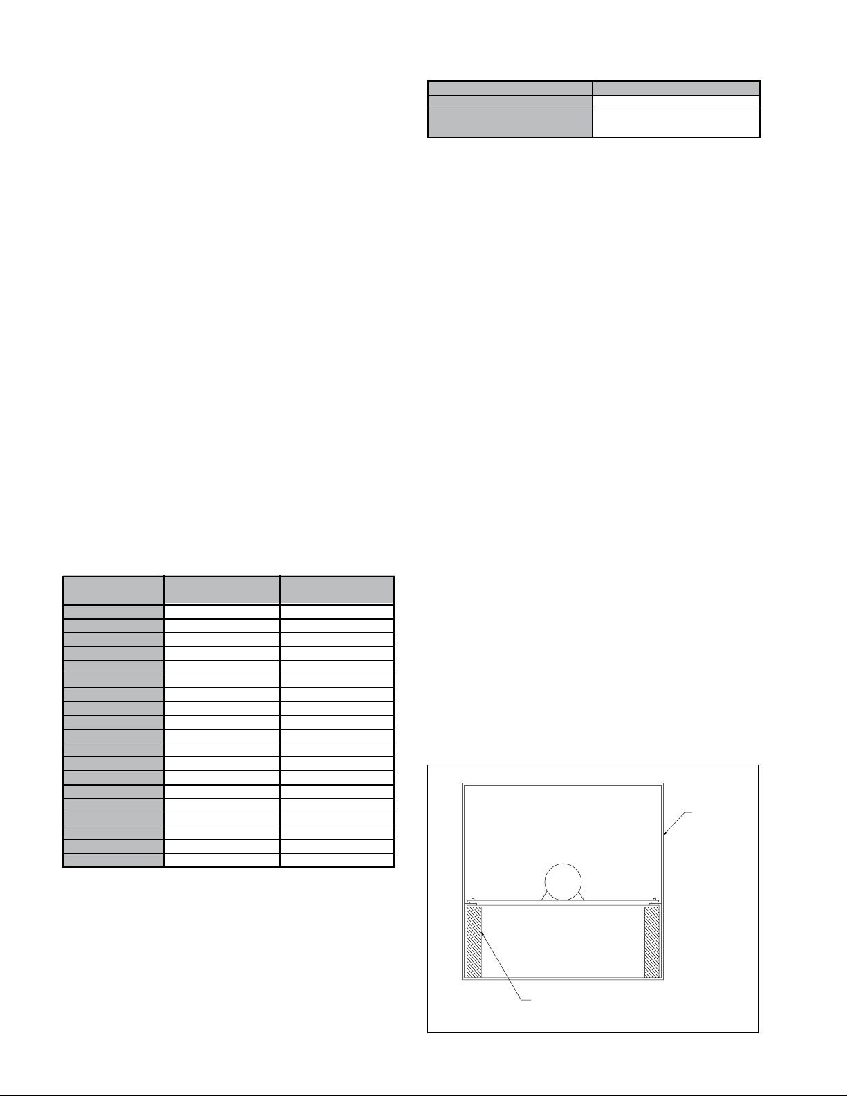
Figure 1. Removal of Wood Shipping Supports
Housing
Maintenance
General
Fan shaft bearings on belt drive units are factory lubricated and require no lubrication for the first 3-6 months
of operation. Lubricate at intervals shown in Table 3
thereafter. With fan running and with a low pressure
grease gun, add grease slowly until a slight bead forms
between the seals. Use Sinclair Litholene, Shell Gadus
S2 V100 2, Socony Vacuum Armvac 781, Sinclair Oil
Stranolith 57 or equal.
2
Instructions: Remove wood shipping supports
frame before installing unit
.
Twin City Fan & Blower IM-3100
Page 3

Figure 2. Wall Application
Louver
Assembly
Fan
Housing
Assembly
Electrical Wiring By Others
Hole Provided for Electrical Entrance Into Unit
Electrical Junction Box With Outlet
Belt Drive Motor
Assembly
Figure 3. Inline Application
Louver Assembly
on Exterior Wall
Direct Drive Motor
Assembly
Wiring By
Others
Ductwork By Others
Trim Angle Assembly
Access To Power Pack of Ventilator
By Removing 4 Fasteners (Interior Side)
or Louvers (Exterior Side)
Duct Adaptor
(Shipped Loose
With Fasteners)
Fiberglass Inlet Venturi
Ductwork By Others
Companion Angles (Shipped Loose)
With Fasteners)
Access to Power Pack of Inline
Unit By Removing 4 Fasteners
Twin City Fan & Blower IM-3100
Dropout Section of Duct For
Easy Maintenance (By Others)
3
Page 4

Limited Warranty
Seller warrants to the original purchaser that the goods
sold hereunder shall be free from defects in workmanship and material under normal use and service (except
in those cases where the materials are supplied by the
buyer) for a period of one year from the date of original
installation or eighteen (18) months from the date of
shipment, whichever occurs first. The liability of seller
under this warranty is limited to replacing, repairing, or
issuing credit (at cost, F.O.B. factory and at seller’s
discretion) for any part or parts which are returned by
buyer during such period provided that:
a. seller is notified in writing within ten (10) days follow-
ing discovery of such defects by buyer, or within ten
(10) days after such defects should reasonably have
been discovered, whichever is less;
b. the defective unit is returned to seller, transportation
charges prepaid by buyer.
c. payment in full has been received by seller or said
products; and
d. seller’s examination of such unit shall disclose to its
satisfaction that such defects have not been caused
by misuse, neglect, improper installation, repair,
alteration, act of God, or accident.
No warranty made hereunder shall extend to any seller
product whose serial number is altered, effaced or
removed. Seller makes no warranty, express or implied,
with respect to motors, switches, controls, or other
components of seller’s product, where such components
are warranted separately by their respective manufacturers. THIS WARRANTY IS EXPRESSLY IN LIEU OF ALL
OTHER WARRANTIES, EXPRESS OR IMPLIED, WHETHER
STATUTORY OR OTHERWISE, INCLUDING ANY IMPLIED
WARRANTY OF MERCHANTABILITY OR FITNESS FOR
A PARTICULAR PURPOSE. In no event shall seller be
liable to buyer for indirect, incidental collateral, or consequential damages of any kind. (BUYER’S FAILURE TO
PAY THE FULL AMOUNT DUE WITHIN SIXTY (60) DAYS
OF DATE OF INVOICE SHALL OPERATE TO RELEASE
SELLER FROM ANY AND ALL LIABILITY OR OBLIGATION
ARISING PURSUANT TO ANY WARRANTY, EXPRESS
OR IMPLIED, WHETHER STATUTORY OR OTHERWISE,
INCLUDING ANY IMPLIED WARRANTY OR
MERCHANTABILITY OR FITNESS FOR A PARTICULAR
PURPOSE, MADE IN CONNECTION WITH ANY
CONTRACT FORMED HEREUNDER. BUYER AGREES
THAT SUCH FAILURE TO PAY SHALL CONSTITUTE A
VOLUNTARY WAIVER OF ANY AND ALL SUCH
WARRANTIES ARISING PURSUANT TO SUCH CONTACT.)
TWIN CITY FAN & BLOWER | WWW.TCF.COM
5959 Trenton Lane N | Minneapolis, MN 55442 | Phone: 763-551-7600 | Fax: 763-551-7601
 Loading...