

Twin City ES-409 User Manual
Aero Acoustic Diffuser
™
INSTALLATION, OPERATION & MAINTENANCE MANUAL
ES-409
June 2010
Contents
Introduction ......................................................................... 1
Shipping .............................................................................. 1
Handling .............................................................................. 1
Storage ................................................................................1
Parts List ............................................................................ 1
Aero Acoustic Diffuser™ Installation ................................ 2
Aero Acoustic Diffuser™ Operation Safety ..................... 2
Operation Checklist ............................................................ 3
Maintenance ........................................................................ 3
Troubleshooting Guidelines................................................ 3
Limitation of Warranties and Claims ............................... 3
Introduction
The purpose of this manual is to provide instructions
that complement good general practices when installing
or operating Twin City Fan & Blower’s Aero Acoustic
Diffuser™ originally provided on the E-Series Plenum
Fan or purchased as an accessory after purchasing the
E-Series plenum fan.
Instructions given in the body of this manual are
general in nature, but apply to only to the E-Series
plenum fan manufactured by Twin City Fan & Blower.
Shipping and Receiving
All Twin City Fan & Blower products are carefully constructed and inspected before shipment to insure the
highest standards of quality and performance.
Compare all the components with the bill of lading
or packing list to verify the proper unit was received.
Check each unit for any damage that may have
occurred in transit. Any damage should be reported
immediately to the carrier and the necessary damage
report filed.
Handling
Handling of all air moving equipment should be conducted by trained personnel and be consistent with safe
handling practices. Verify the lift capacity and operating
condition of handling equipment. Maintain handling
equipment to avoid serious personal injury.
Units shipped completely assembled, mounted to the
fan, require minimal handling. Use only designated lifting
lugs on fan framework for handling the fan.
Partial or disassembled units require special handling.
All parts should be handled in a fashion that protects
the parts from damage. Components should be handled
such that forces are not concentrated and bending or
distortion cannot occur.
Aero Acoustic Diffusers™ should be lifted using
straps or padded chains if necessary. Do not distort the
components when lifting. Deformed components are a
source of interference between the fan impeller and the
Aero Acoustic Diffuser™ resulting in excessive noise and
possibly fan impeller imbalance.
Storage
If the Aero Acoustic Diffuser™ installation is to be
delayed, store the unit in an indoor, protected area.
Protect the Aero Acoustic Diffuser™ from moisture and
possible incidental contact. A temperature controlled
storage facility is preferred.
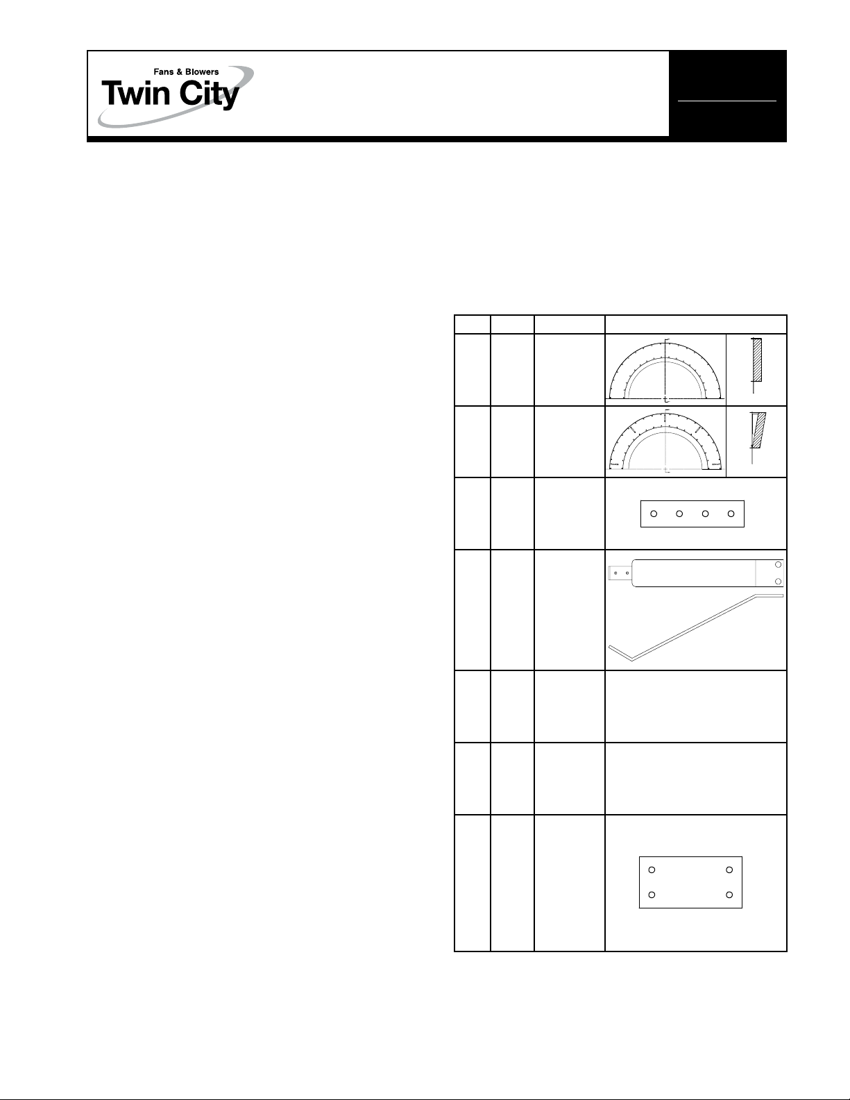
Parts List
Item Qty Part Name Sketch
Backplate
4
(Only
re-
for
Sizes
807)
Diffuser
(Two (2)
Halves)
Frontplate
Diffuser
(Two (2)
Halves)
Diffuser
End
Connector
Diffuser
Mounting
Brackets
1
/4"-20
Self Tap
Screws
3
/8"-16
Bolt & Nut
Diffuser
Side
Connector
1 1
2 1
3 4
4 8
5 48
6 16
quired
7
300 to
A
A
A
A
N/A
N/A
SECTION A-A
SECTION A-A
©2010 Twin City Fan Companies, Ltd.

Aero Acoustic Diffuser™ Installation
Follow the proper handling instructions given earlier. If
mounting slots are not supplied, proceed to Step 1; if
mounting slots are supplied on fan, proceed to Step 3:
1. Using the formulas below, calculate mounting hole
locations. (See Figure 1):
“A” = Measured in the field. (Distance from inside
frame to impeller backplate)
“B” = Measured in the field. (Distance from impeller
backplate to impeller frontplate)
“C” = “A”–1.40
“D” = “A”+“B”+“F”
“E” = See Table 1
“F” = See Table 1
2. Measure, mark and drill mounting bracket holes as
shown (See Figure 1). Note: Holes are required on
both sides of fan on the top and bottom frame rails
for sixteen (16) holes. Lifting lugs may need to be
removed.
Table 1.
Size E F
122 0.89 0.03
150 0.89 0.00
165 0.89 0.00
182 0.93 0.16
200 0.93 0.13
222 1.13 0.13
245 1.13 0.19
270 1.13 0.16
300 1.13 0.16
330 1.13 0.16
Size E F
365 1.19 0.15
402 1.19 0.16
445 1.19 0.15
490 1.19 0.15
542 1.19 0.12
600 1.19 0.46
660 1.19 0.58
730 1.19 0.41
807 1.19 0.31
4. Insert each diffuser section into the fan frame. As
shown in Figure 3. The backplate diffuser mounts on
backplate side of impeller; the frontplate diffuser
mounts on the frontplate side of impeller. Note:
Perforated side of diffuser sections must be in the air
path (see Figure 3).
Figure 3.
PERF PLATE TO BE FLUSH
BACKPLATE
DIFFUSER
WITH END OF BACKPLATE
ON WHEEL
FRONTPLATE
DIFFUSER,
LOCATE AS
CLOSE TO
FRONTPLATE
TIP AS
POSSIBLE
5. With the four (4) diffuser sections located inside the
fan framework, use the screws and connector brackets removed in Step 3 to reassemble the two (2)
diffuser halves back together as shown in Figure 4.
Figure 4.
Figure 1.
D
B
1.25
TYP.
(16) 0.56 SLOTS
(8) ONE EACH SIDE
C
E
A
3. If not done so, separate backplate diffuser and frontplate diffuser into two (2) halves by removing connector brackets provided. Four (4) diffuser pieces will
result. (See Figure 2)
Figure 2.
Figure 5.
2
Twin City Engineering Supplement 409
 Loading...