

Page 1

Fans with CE Mark
INSTALLATION, OPERATION & MAINTENANCE MANUAL
ES-2-06
March 2013
Contents
Introduction .........................................................................1
Personal Protection ............................................................1
Hazardous Materials........................................................... 1
Installation
Shipping and Receiving ................................................1
Handling .........................................................................2
Unit Storage ................................................................... 2
Foundations and Supporting Structures
- Industrial Fans .......................................................2
Fan Installation - Factory Assembled Units ............... 3
Fan Installation - Disassembled Units ........................4
Bearing Installation ........................................................ 5
Grouting .......................................................................... 8
Drive Mounting .............................................................. 8
Flexible Couplings ......................................................... 8
Duct Connections ..........................................................8
Guards and Enclosures ................................................8
Electrical Supply and Controls .................................... 9
Maintenance
Motor Maintenance ....................................................... 9
Drive Maintenance ....................................................... 10
Bearing Maintenance ................................................... 10
Wheel and Shaft Maintenance ...................................10
Structural Maintenance ............................................... 10
Fan Operation
Proper Use and Application....................................... 10
Sound ........................................................................... 11
Operation Checklist .....................................................12
Optional Accessories ................................................... 12
Troubleshooting Guidelines ......................................... 12
Disposal ........................................................................ 13
Appendix A - Commercial Ventilator Installation
Instructions ................................................................... 13
Appendix B - Axial Fans ................................................ 14
Introduction
This bulletin has been prepared to guide the users of
fans in the proper installation, operation and maintenance procedures to insure maximum equipment life with
trouble-free operation. Personnel operating or maintaining
this equipment shall be trained in the proper procedures
for doing so.
Since many fans of this type have custom features or
components, please refer to the attached documentation
and appendices for additional information. When manufacturers of components provide detailed installation and
operation manuals, they will be provided. Because of the
wide variety of equipment covered in this bulletin, the
instructions given here are general in nature.
For safe installation, startup and operational life of
this equipment, it is important that all involved with the
equipment be well versed in proper fan safety practices
and read this bulletin. Please review the safety section
before beginning any work. It is the user’s responsibility to make sure that all requirements of good safety
practices and any applicable safety codes are strictly
adhered to. Only properly trained personnel should operate and maintain this equipment.
©2013 Twin City Fan Companies, Ltd.
Personal Protection
For safety reasons maintenance personnel should wear
personal protection equipment when attempting to maintain fans. People with long hair are advised to tuck hair
back possibly into a cap.
Personal protection equipment should include the
following:
• Safety glasses or goggles approved by local safety
authority
• Protective shoes with steel toecaps and oil resistant soles
• Heavy gloves that can cope with sharp edges or
exposure to hazardous chemicals. This is especially
important when hazardous residues are present in
fans.
• Breathing apparatus if toxic gases or vapors are
expected to be present.
• Close fitting clothing
Do not wear:
• Rings
• Bracelets
• Necklaces
• Loose items of clothing
It is the responsibility of the maintenance personnel
to determine that the lighting is sufficient for the work
being performed. Additional portable lighting may be
required as there are no lighting fixtures supplied with
the fans.
Hazardous Materials
Twin City Fan Companies, Ltd. is not always made
aware of the materials that may be handled with a fan
and therefore can not warn the user of these hazards.
Because of this, the end user must identify the material hazards present and indicate this on the fan with
a warning label. If there is risk of residual hazardous
material being left in a fan if the gas or vapor being
handled can accumulate as a deposit, all maintenance
and operation personnel must be trained to handle such
hazards before having access to the fan.
Lubricants used on fan components could be hazardous if they contact someone’s eyes or are consumed.
For additional general safety practices for air moving
equipment, see AMCA Bulletin 410.
Installation
Shipping and Receiving
All Twin City Fan Companies, Ltd. products are carefully
constructed and inspected before shipment to insure the
highest standards of quality and performance. Compare
all components with the bill of lading or packing list to
verify that the proper unit was received. Check each unit
for any damage that may have occurred in transit. Any
damage should be reported immediately to the carrier and
the necessary damage report filed.
Page 2
Handling
Handling of all air moving equipment should be conducted by trained personnel and be consistent with safe
handling practices. Verify the lift capacity and operating condition of handling equipment. Maintain handling
equipment to avoid serious personal injury.
On most units, lifting lugs are fashioned to protect
the fan and fan housing from damage. Secure lifting
equipment to all provided lifting lugs to avoid instability
while moving the equipment. Units shipped completely
assembled may be lifted with slings and spreader bars.
(Use well-padded chains, cables or nylon straps.) Never
lift a fan by the inlet or discharge flange, shafting or
drives, wheel or impeller, motor or motor base, or in any
other manner that may bend or distort parts. Never lift
with slings or timbers passed through the fan inlets.
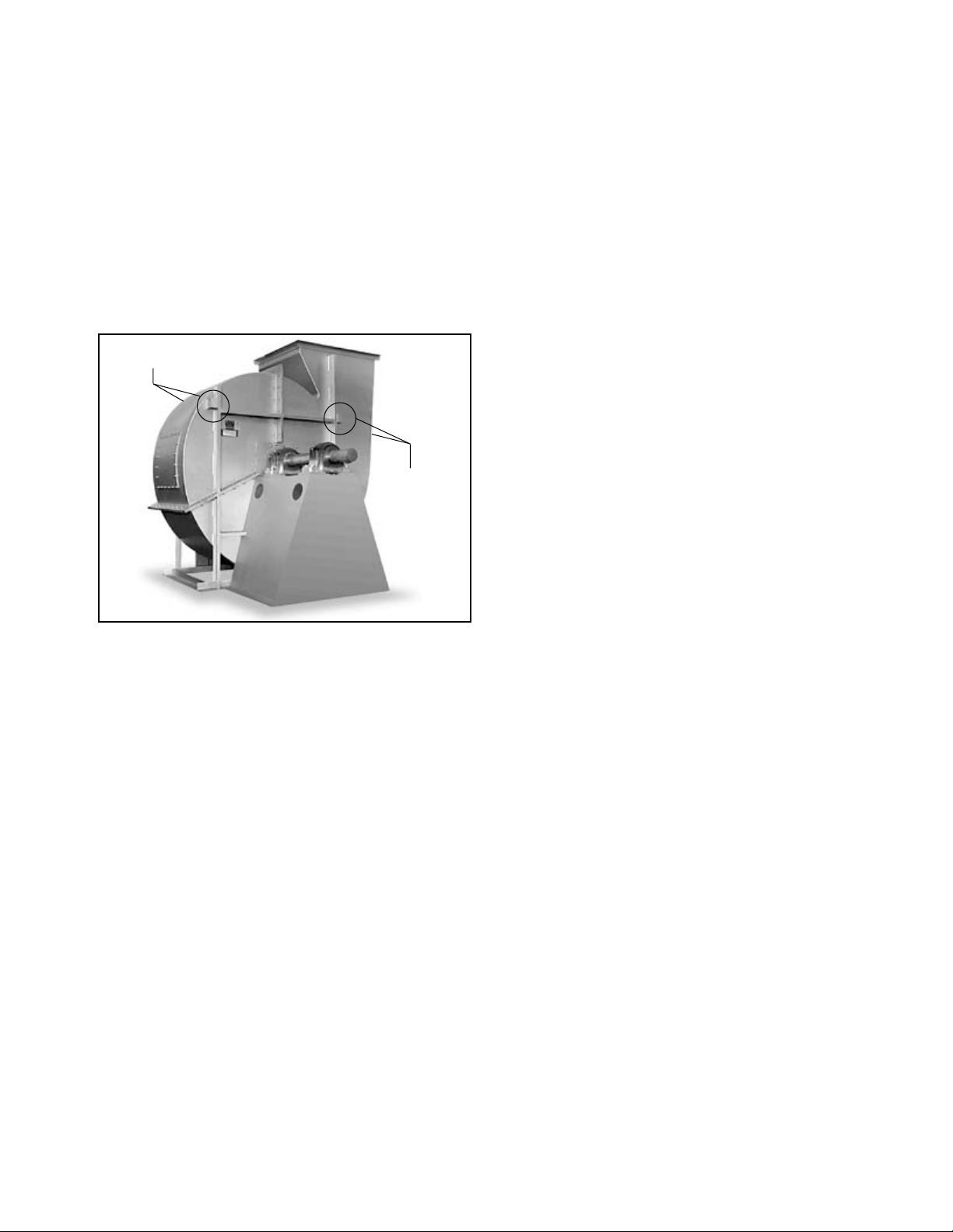
Figure 1. Lifting Lug Locations
Lifting Lugs
Lifting Lugs
Partial or disassembled units require special handling. All
parts should be handled in a fashion which protects the
coatings and parts from damage. Components should be
handled such that forces are not concentrated to avoid
bending or distortion.
The housing should be lifted using straps and spreaders. Do not distort housing or side plates when lifting.
Bearing pedestals should be lifted using straps or
padded chains. Under no circumstance should an
attached or separated bearing pedestal be lifted by the
shaft, bearings, drives, motor or wheel.
The shaft and wheel assembly may be lifted using
a hoist and a spreader with a sling around the shaft
at points nearest the wheel. Use the spreader bar to
ensure that the slings do not push against the sides of
the wheel as this may distort the wheel. Take care not
to scratch the shaft where the wheel or bearings will
be mounted. Never lift or support the assembly by the
wheel. Always support the assembly by the shaft when
lifting or storing. Do not support the shaft or the wheel
on the housing sides.
Wheels shipped separately can be lifted by slings running between the blades or around the hub. Never lift
the wheel by blades or flanges. Always transport wheels
by lifting. Do not roll the wheel as this can damage
coatings and change the balance of the wheel.
Bent shafting is a source of vibration and bearing
failure, so handle the shaft with care. Any scratches on
the shaft may be removed with fine emery cloth or a
stone.
For roof ventilators, also see instructions specific to
handling roof ventilators in Appendix A.
Pins to hold insulation to the housing are supplied
for some high temperature fan designs. Use caution
when handling and working around fans that have these
insulation pins as the points are sharp.
Unit Storage
If fan installation is to be delayed, store the unit in
an environmentally stable and protected area. Vibration
should not exceed 0.051 mm peak – peak displacement
at the storage site unless the fan is properly isolated
from the vibration. The unit should be reasonably protected from any accidental impacts. Cover the fan to
protect coatings and to prevent any foreign material or
moisture from entering the inlet or discharge. Take care
to protect the motor, drives and bearings. The following
precautions should be taken during extended storage to
ensure the equipment is not damaged:
• Extended storage requires monthly inspections.
Check for corrosion or damage to the unit and for
debris within the fan.
• Bearings tend to take on moisture if the atmosphere they are stored in is not at a constant
temperature. To avoid corrosion, it is necessary to
keep the bearings full of grease and to rotate them
periodically. Even when full of grease, bearings will
take on moisture, so it is necessary to purge the
bearings with new grease to expel moisture every
thirty days. It is recommended that the bearings be
purged with grease while being rotated by hand.
Do not use high-pressure greasers as they may
ruin the bearing seals.
• The drives and belts should be removed if the fan
is to be stored for a prolonged period. The drives
should be labeled for service and stored in a dry
place. Belts should be removed, coiled without
kinks, placed in a heavy carton, and stored in a
dry, well-ventilated place. To prevent belt deterioration storage conditions should not exceed 85°F
and 70% humidity. If belts show signs of deterioration, they should be replaced prior to startup.
• Motors should be stored in a clean, dry, vibrationfree location. The packaging should be opened up
enough to allow air circulation around the motor.
The winding temperature should be kept slightly
above that of the surroundings to prevent condensation. This can be accomplished by energizing
the internal heaters, if the motor is so equipped,
or by using space heaters. If it is impossible to
heat the windings, the motor should be wrapped
tightly with a waterproof material that also encloses
several bags of desiccant. Replace the desiccant
regularly to prevent moisture problems. The motor
rotor should also be rotated regularly (monthly) to
assure the bearing parts are well greased.
Foundations and Supporting Structures
— Industrial Fans
The best means of floor mounting a fan is on a welldesigned, flat, level concrete foundation. The foundation
should have a mass of at least three times that of
the supported assembly. The foundation should extend
150mm beyond the outer dimensions of the fan and
driver; however, it should be no more than twice the
area required for the equipment. If it is made larger, the
mass should be increased accordingly to resist rocking
modes of vibration. J or T type anchor bolts using one
size smaller than the nominal dimension of the base hole
shall be used. Anchor bolts should be tied into the reinforcing bar of the foundation for the foundation. A pipe
2 Twin City Fan Engineering Supplement 2-06
Page 3
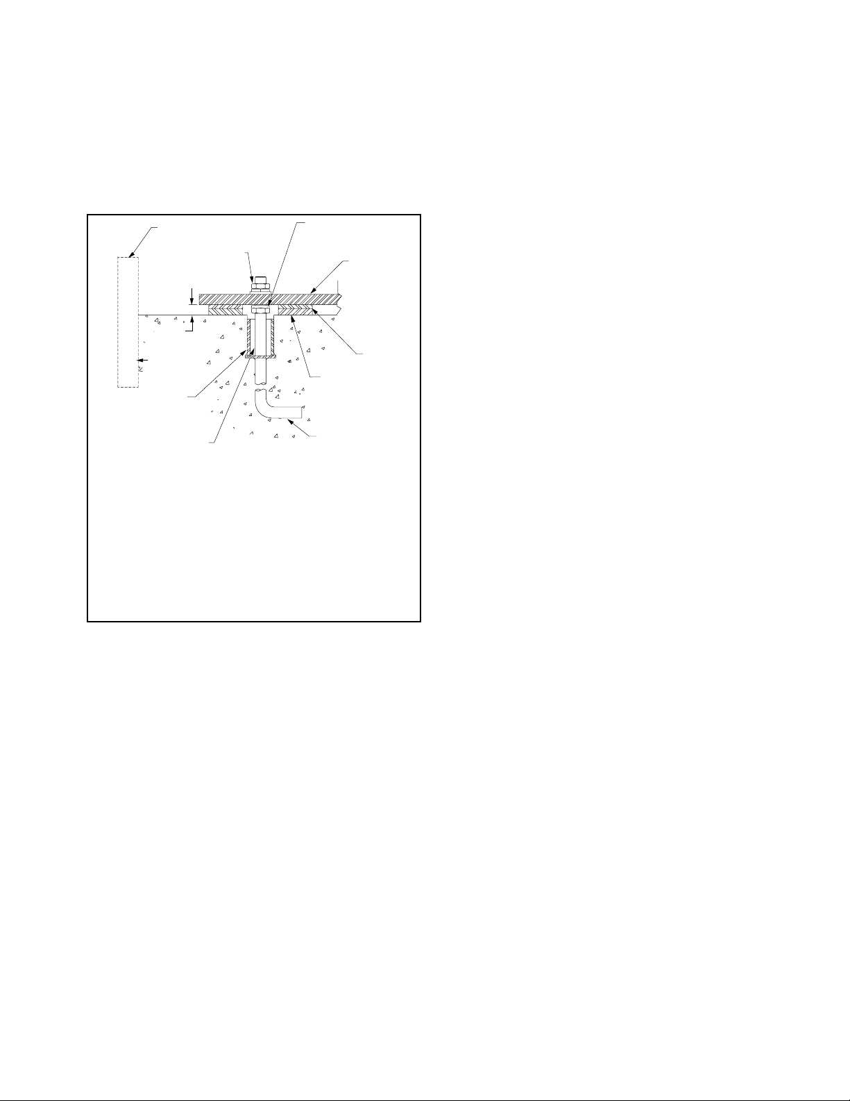
sleeve with a diameter of 2 to 21⁄2 times the anchor
bolt diameter should be provided around the anchor bolt
for final adjustment (see Figure 2). The mounting surface of the foundation should be smooth for good shim
contact. When deciding the thickness of the foundation,
approximately 25 to 40mm height should be allowed for
shimming, grouting, leveling, washers, nuts, etc.
The foundation plan on the customer submittal drawing indicates the mounting hole size and locations on
the fan.
Figure 2. Typical Foundation Section
Fan Installation - Factory Assembled Units
General instructions for industrial centrifugal fans – For Axial
fans and commercial ventilators, follow steps below noting
instructions specific to those fan types in Appendix A and B.
Follow proper handling instructions as given earlier.
1. Move the fan to the final mounting position.
2. Remove skid, crates and packing materials carefully.
3. If vibration isolation is to be used, place isolation
base on mounting bolts. Line up holes in fan base
with bolts as indicated on the foundation plan of
the customer submittal drawing.
4. Consult each specific fan’s submittal drawing for
proper installation arrangement and mounting dimensions. Place the fan on mounting structure. Carefully
level the unit (checking the level on the shaft) on
the foundation and shim as necessary using stainless steel shims on both sides of each anchor bolt.
Anchor bolts are to be pre-tensioned per Table 1.
For metric grade bolts or materials not shown in
Table 1, check with bolt manufacturer for the proper
torque. (See details specific to commercial ventilators in appendix A for this step).
5. Check the alignment of the bearings. Shim or
reposition the bearings if necessary. In many split
housing roller bearings, the gap between the seal
NOTES:
1. Temporary form for grout pouring.
2. Hex nut, split ring lock washer and tapered or flat washer.
3. 1" to 1.5" grout allowance to be filled with nonshrinking machinery grout.
4. Pipe-bolt sleeve diameter 2 to 2
rection of alignment errors.
5. Care should be taken that anchor bolt sleeves are filled with
grout.
6. J-Bolt leg should be fastened to foundation rebar.
7. Shimming surface to be smooth, level, dressed if necessary.
8. Full width stainless steel shims.
9. Fan base angle or structural steel.
10. Leveling nut, if used, should be backed off after shimming for
final tightening of hex nuts.
1
/2 times bolt diameter for cor-
carrier and housing can be measured with a feeler
gage. The variation in this gap should be less than
half of the maximum gap measured. In roller bearings where this gap is not visible, alignment can
be verified by verifying the bearing is square with
the pedestal top. In ball bearings, the bearing outer
ring swivels in the housing to accommodate a small
amount of misalignment. Verify bearing set screws,
cap bolts, and collars are tightened per Tables 2a,
2b and 2c.
6. Check face alignment of sheaves on belt driven fans.
Parallel alignment should be within 5mm per meter of
center distance. Angular Misalignment should be less
than 1 degree. Check and record tension of belts
If a structural steel base or platform is to be used, the
structure must be designed for the weight of the fan,
live loads imposed by rotation of the rotor and driver,
and any external live loads. The structure should be
designed to ensure that no natural frequency will occur
within 30% of the fan speed. This is especially true if
the structure supports more than one fan.
Any ducting should have independent support. Do
not use the fan to support ducting. The fan frame
can be designed to carry some external loads. Consult
the factory if this is a concern. Isolating the fan from
ductwork with flex connections eliminates transmission
of vibration. Fans handling hot gases require expansion
joints at both the inlet and discharge to prevent excessive loads caused by thermal growth. Refer to AMCA
Publication 201 for good practices in ductwork geometry
and configuration. When possible, ductwork shall be
located where there is least risk of personnel tripping,
walking into or falling over the ductwork. If not possible,
warnings shall identify this hazard.
See Appendix A Commercial Ventilator Installation
Instructions for commercial ventilator foundation details.
Fans should not be located underneath other machinery where there might be a risk of harmful liquid falling
onto fans from above.
Fans should be installed where they are readily accessible to maintenance personnel, so that such personnel
are not required to stoop or crawl to access fans.
to see if it is sufficient. Proper belt tension is specified on the included datasheet. If belt tension needs
adjustment, instructions on belt tensioning are given
in the Drive Mounting section of this manual. Sheaves
on belt driven fans are often provided with taperlock
bushings. When tightening bushing bolts, proceed in a
progressive manner to avoid cocking the tapered surfaces between the bushing and the sheave. Bushing
bolt torque specifications are indicated in Table 3.
7. Check alignment of factory mounted couplings, as
they are subject to misalignment during shipment.
Realign if necessary in accordance with the instructions which are included with the shipment. NOTE:
Most couplings need lubrication.
8. Make sure there is no rubbing or binding and that
the wheel-inlet cone or wheel to fan housing clearances and overlap are correct. Overlap values or
other dimensions to verify proper wheel location are
given in the included documentation specific to the
fan. Wheel clearance should be verified to match
the specified value and be uniform. The measured
values should be recorded.
9. Check the tightness of the wheel on the shaft per
Table 4. The measured torque should be recorded.
10. Check the tightness of foundation bolts, motor
mounting bolts, and bearing mounting bolts per
Table 1. For metric bolts or grades not specified in
Table 1, check proper torque values per the bolt
3 Twin City Fan Engineering Supplement 2-06
manufacture.
Page 4
11. Check that bearings are fully lubricated and check
Assembled Bearing,
the oil level in the static oil lube systems (if
supplied).
12. Install any accessories shipped loose from the
factory.
Fan Installation - Disassembled Units
General instructions for industrial centrifugal fans – For Axial
fans (including mounting arrangements for inline centrifugal
fans), follow assembled fans instructions above and use
Appendix B for assembly details.
A unit is considered “disassembled” if any component
required for proper operation is shipped or supplied separately or in pieces. Reference earlier instructions concerning proper handling of fan components. Assembly shall
only be performed by trained personnel familiar with the
assembly of this type of equipment.
1. Move the lower half of the housing to its mounting
location (split housing).
2. Remove skids, crates, and packing materials carefully.
3. If vibration isolation is to be used, place the vibration isolation base on mounting bolts. Line up holes
in fan base with bolts.
4. Place the lower housing on the mounting structure.
Carefully level the lower housing on the foundation
and shim as necessary using stainless steel shims
on both sides of each anchor bolt.
5. If the bearing pedestal(s) are separated they should
be installed next.
a. Move bearing pedestal(s) to mounting location.
b. Put vibration base, if any, in place. Set pedestal(s)
on bolt(s).
c. Do not distort bearing pedestal by forcing it to
align with a non-level foundation. Shim beneath
the pedestal as necessary.
d. Check the bearing centerline height. Adjust the
height to match centerline height of the housing. High temperature units may require a lower
housing centerline when cold so that it will be
centered when hot.
e. Bring the bearing pedestal into square with the
housing using careful measurements or a large
square.
f. Bolt the pedestal into position.
6. If the wheel and shaft were shipped unassembled,
you must now install the shaft in the wheel.
a. First use solvent to clean the protective coating
off the shaft. Check all surfaces for corrosion or
nicks and clean if necessary with fine emery cloth
or a stone. After thoroughly cleaning the shaft
with solvent, do not touch it with bare hands as
perspiration can cause rust or pitting over time.
b. Remove keys from the shaft.
c. Clean the inside of the wheel bore with solvent.
Make sure the setscrews will not interfere when
inserting the shaft into the wheel bore.
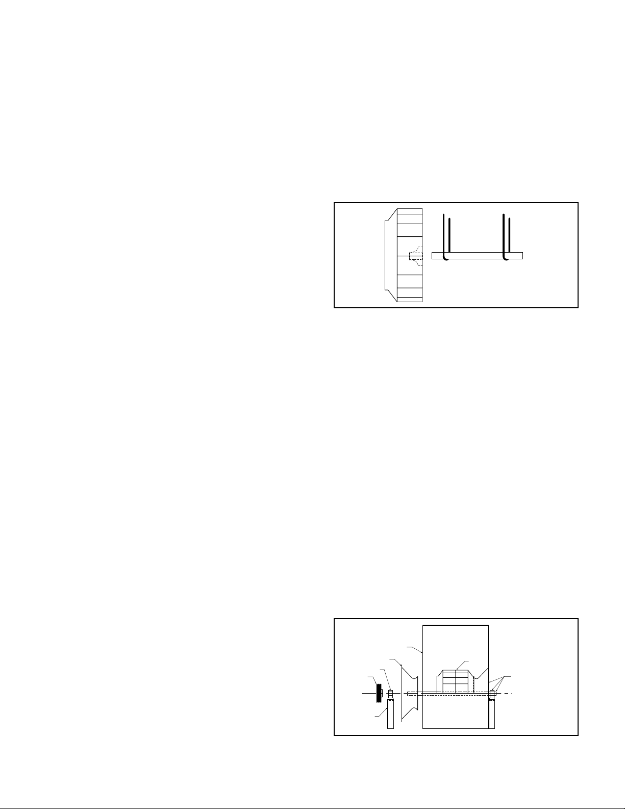
7. Arrangement 1, 9 or 10: Drive Component
Assembly:
a. Insert shaft into wheel from back side of wheel
(Fig 3).
b. When shaft is flush with wheel hub, put key into
keyway and tighten wheel setscrews (for straight
bore hubs), or for bushing bore hubs, progressively tighten the bushing bolts per Table 3.
Record the measured torque value.
c. Insert shaft through opening in drive side. (If
splithoused unit, lower into position.)
d. Install bearings onto shaft. Do not tighten bear-
ing setscrews at this time. The bearing housing
should be perpendicular and the bearing base
parallel to the axis of the shaft to prevent loads
caused by misalignment.
e. Mount assembly, bolt bearings to drive stand.
Shaft must be parallel with side of bearing
pedestal.
Figure 3. Drive Component Assembly
8. Arrangement 3 (Split-housed) units (See Figure 4):
a. Parts on DWDI units are assembled in the fol-
lowing order as viewed from opposite drive side:
Bearing bar assembly and opposite bearing, funnel, (housing side), wheel, (housing side), funnel,
drive side bearing bar assembly, drive bearing
and sheaves. Mount bearing bar assembly to
housing. Center wheel in funnels.
b. Parts on SWSI units are assembled in the
following order as viewed from opposite drive
side: Bearing bar assembly and opposite bearing,
funnel, (housing side), wheel, (housing side),
drive side bearing bar assembly, drive bearing
and sheaves. Mount bearing bar assembly to
housing.
c. Assemble parts in above order on shaft.
d. Move assembly into position. Lightly bolt bearings
into place.
e. Shaft should be parallel with discharge of hous-
ing. Move bearings to accommodate. Follow
bearing alignment instructions per step 5 in factory assembled units section above.
f. Level shaft; shim bearings if required. Tighten
bearing setscrews.
Figure 4. Split-housed Drive Component Assembly
Housing Side
Inlet Funnel
Bearing
Sheave
Shaft
Centerline
Bearing
Pedestal
Wheel
Shaft, Funnel, and
Housing. Frame
Angles Not Shown.
9. Install motor on base. Carefully align shafts for drive
installation.
4 Twin City Fan Engineering Supplement 2-06
Page 5

10. Mount drives as follows:
a. Slip (do not pound) proper sheave onto cor-
responding shaft. CAUTION: PLACING FAN
SHEAVE ON MOTOR CAN OVERSPEED WHEEL
AND CAUSE STRUCTURAL FAILURE.
b. Align sheaves with a straight-
edge extended along the
Figure 5.
Sheave Alignment
perimeters of both sheaves,
just making contact in two
places on outside perimeters
of both sheaves (see Figure
5). Parallel alignment should
be within 5mm per meter
of center distance. Angular
Misalignment should be less
than 1 degree.
c. Tighten down sheave bolts.
d. Install a matched set of
belts. Adjust belt tension as
indicated in “Drive Mounting”
step #3.
Table 1. Bolt Tightening Torque
Size
1/4 - 20
5/16 - 18
3/8 - 16
7/16 - 14
1/2 - 13
5/8 - 11
3/4 - 10
7/8 - 9
1 - 8
1 1/4 - 7
Grade 2 Grade 5 Grade 8 Aluminum Stainless
(Ft - lbs) (N - m) (Ft - lbs) (N - m) (Ft - lbs) (N - m) (Ft - lbs) (N - m) (Ft - lbs) (N - m)
5.5 7.5 8 10.8 12 16.3 3.8 5.2 6.3 8.5
11 15 17 23 25 34 6.7 9.1 11 15
22 30 30 41 45 61 11.9 16 19 26
30 41 50 68 70 95 19 26 31 42
55 75 75 102 110 149 26 35 43 58
100 136 150 203 220 298 59 80 92 125
170 230 270 366 380 515 81 110 128 174
165 224 430 583 600 813 125 169 194 263
250 339 645 874 900 1220 184 249 287 389
500 678 1120 1518 1500 2034 336 456 523 709
e. Tighten belts to proper belt tension. Record the
belt tension used. See drive mounting section for
tensioning instructions. Proper tension is specified
in the datasheet included with the fan.
11. Fans that have motors and drives mounted at the
factory are trim balanced prior to shipment. This
is not possible on units that are shipped without
motors and drives. The addition of drive components in the field can create unbalance forces. Twin
City Companies, Ltd. recommends final balancing
of the unit after the drive components are installed.
Failure to do so voids the Twin City Fan Companies,
Ltd. warranty.
12. Repeat the installation checks indicated for factory
assembled units to assure proper tightness and
alignment of all components.
Bearing Installation
Bearings are only to be field installed when accompanied by installation instructions from the bearing manufacturer. When field installation is required, follow the
manufactures instructions carefully to install bearings.
Table 2a. Bearing Cap Bolt Torque Specifications (see page 6)
Table 2b. Metric Set Screw Torque Specifications
METRIC SHAFTS SET SCREW SIZE LOCKING COLAR SCREW SIZE
Manufacturer BRG ID Units M5 M6 M8 M10 M12 M4 M5 M6 M8
Dodge
Dodge
Dodge
SKF
Manufacturer BRG ID Units 12-35mm 40-45mm 50-65mm
SKF
Linkbelt
Table 2c. IP Set Screw Torque Specifications (see page 7)
S2000 N-m - - 17.8 35 57 - - - SCAH N-m 3.4 6.9 16 28 51 5.85 10.75 20.5 45
SCMAH N-m 3.4 6.9 16 28 51 5.85 10.75 20.5 45
SY N-m See Below 4.2 7.4
SY BEARING DIAMETER PB224 BEARING DIAMETER
70-100mm
SY N-m 4 6.5 16.5 28.5 - - - - -
PB224 N-m - - - - 21 37 52 77 153
25,30mm 35-50mm 55mm
60-80mm 90,100mm
Table 4. Set Screw Tightening Torque (other than bearing
set screws)
Table 3. Browning Split Taper Bushing Tightening Torque
Bolt
Size
1/4 - 20
5/16 - 18
3/8 - 16
1/2 - 13
Bushing
Type
H 8 11 8 11
P, B 17 23 13 18
Q, R 30 41 24 33
S 70 95 - -
Iron/Steel Hub,
Sheave
Ft - lbs N - m Ft - lbs N - m
Aluminum
Hub
Set Screw
Size
1/4 - 20
5/16 - 18
3/8 - 16
7/16 - 14
1/2 - 13
5/8 - 11
3/4 - 10
7/8 - 9
1 - 8
1 1/4 - 7
Steel Set Screws Stainless Set Screws
Ft - lbs N - m Ft - lbs N - m
5.5 7.5 5.8 7.9
11 15 11 15
22 30 19 26
30 41 28 38
55 75 42 57
100 136 82 111
170 230 115 156
165 224 - 250 339 - 500 678 - -
5 Twin City Fan Engineering Supplement 2-06
Page 6

(N-m)
TORQUE
(FT-LBS)
TORQUE
SEALMASTER
(RPB & RPB-M SERIES)
MODEL
(N-m)
TORQUE
(FT-LBS)
LINK-BELT
TORQUE
(PLB6800 SERIES)
PRPB-100M (exp) 150 203
RPB-315 (exp) 150 203
RPB-105M (fixed) 266 360
RPB-105M (exp) 150 203
RPB-110M (fixed) 266 360
RPB-110M (exp) 150 203
RPB-407 (fixed) 266 360
RPB-407 (exp) 150 203
RPB-115M (fixed) 266 360
RPB-115M (exp) 150 203
RPB-120M (fixed) 394 534
RPB-120M (exp) 266 360
RPB-125M (fixed) 394 534
RPB-125M (exp) 266 360
RPB-415 (fixed) 394 534
- - -
RPB-415 (exp) 266 360
SETSCREW
SETSCREW
TORQUE
SKF
TORQUE
(SAF SERIES)
TORQUE
TORQUE
MODEL
NUT
(N-m)
FOR LOCK
NUT
(FT-LBS)
FOR LOCK
SAE
GRADE 8
CAP BOLTS
SAE
GRADE 8
CAP BOLTS
METRIC
GRADE 8.8
CAP BOLTS
METRIC
GRADE 8.8
CAP BOLTS
PLB6863 160-180* 217-244* RPB-315 (fixed) 266 360
(N-m)
(FT-LBS)
(N-m)
(FT-LBS)
MODEL
SAE
(N-m)
TORQUE
GRADE 5
- - - - - - - - - - - - - RPB-85M 266 360
520 208-260 282-352 SAF22520 150 203 380 515 13 17 PLB6855 160-180* 217-244* RPB-307 266 360
85mm
3.438"
- - - - - - - - - - - - RPB-95M 266 360
- - - - - - - - - - PLB68M90 160-180* 217-244* RPB-90M 266 360
-
90mm
95mm
- - - - - - - - - - PLB68M100 160-180* 217-244* PRPB-100M (fixed) 266 360
522 208-260 282-352 SAF22522 150 203 380 515 13 17
3.938"
100mm
- - - - - - - - - - - - -
105mm
- - - - - - - - - - PLB68M110 160-180* 217-244*
526 320-430 433-583 SAF22526 295 399 900 1220 26 35 PLB6871 280-330* 379-447*
4.438"
110mm
- - - - - - - - - - PLB68M115 280-330* 379-447*
- - - - - - - - - - - - -
115mm
120mm
- - - - - - - - - - PLB68M125 400-430* 542-583*
528 512-640 694-867 SAF22528 295 399 900 1220 - - PLB6879 400-430* 542-583*
4.938"
125mm
- - - - - - - - - - PLB68M135 400-430* 542-583*
532 512-640 694-867 SAF22532 - 380 515 - PLB6887 400-430* 542-583* - - -
5.438"
135mm
- - - - - - - - - - PLB68M140 400-430* 542-583* - - -
- - - - - - - - - - PLB68M150 400-430* 542-583* - - -
140mm
150mm
- - - - - - - - - - PLB68M160 400-430* 542-583* - - -
534 512-640 694-867 SAF22534 - 380 515 - - - - - - -
5.938"
160mm
536 512-640 694-867 SAF22536 - 380 515 - - - - - - -
6.438"
DODGE
SAE
TORQUE
(USAF SERIES)
Table 2a. Bearing Cap Bolt Torque Specifications
SHAFT
(FT-LBS)
GRADE 5
MODEL
DIA.
- - - - - - - - - - - - - PRB-35M 31 42
509 24-30 32-40 SAF22509 45 61 70 94 6 8 PLB6823 45-50* 61-67* RPB-107 31 42
35mm
1.438"
- - - - - - - - - - PLB68M40 45-50* 61-67* RPB-40M 31 42
- - - SAF22510 45 61 70 94 6 8 PLB6827 45-50* 61-67* RPB-111 31 42
40mm
1.688"
- - - - - - - - - - PLB68M45 45-50* 61-67* RPB-45M 31 42
- - - SAF22511 60 81 110 149 13 17 PLB6831 45-50* 61-67* RPB-115 31 42
45mm
1.938"
- - - - - - - - - - PLB68M50 45-50* 61-67* RPB-50M 31 42
- - - - - - - - - - - - - RPB-55M 31 42
50mm
55mm
- - - - - - - - - - PLB68M60 45-50* 61-67* RPB-60M 75 101
513 40-50 54-67 SAF22513 60 81 110 149 13 17 PLB6835 45-50* 61-67* RPB-203 31 42
60mm
2.188"
- - - - - - - - - - PLB68M65 45-50* 61-67* RPB-65M 75 101
515 60-75 81-101 SAF22515 60 81 110 149 13 17 PLB6839 45-50* 61-67* RPB-207 75 101
65mm
2.438"
- - - - - - - - - - PLB68M70 90-100* 122-135* RPB-70M 75 101
516 120-150 162-203 SAF22516 110 149 220 298 13 17 PLB6843 90-100* 122-135* RPB-211 75 101
70mm
2.688"
- - - - - - - - - - PLB68M75 90-100* 122-135* RPB-75M 75 101
517 120-150 162-203 SAF22517 110 149 220 298 13 17 PLB6847 90-100* 122-135* RPB-215 75 101
75mm
2.938"
- - - - - - - - - - PLB68M80 90-100* 122-135* RPB-80M 266 360
80mm
6 Twin City Fan Engineering Supplement 2-06
- - - - - - - - - - PLB68M170 630-700* 854-949* - - 538 896-1120 1214-1518 SAF22538 - - 600 813 - - - - - - - -
6.938"
170mm
* Lower torque values are for oil lubricated threads.
Page 7

Table 2c. IP Set Scew Torque Specifications
INCH SHAFTS
MANU-
FACTURER
SEAL-
MASTER
SKF
SEAL-
MASTER
SEAL-
MASTER
SEAL-
MASTER
SEAL-
MASTER
SKF
LINKBELT /
REXNORD
SEAL-
MASTER
SEAL-
MASTER
DODGE
DODGE
DODGE
SKF
BROWN-
ING
BROWN-
ING
BRG
ID
RP FT-LB 2.3 5.5 5.5 10.5 10.5 19 19 19 - - - - - -
SY FT-LB 7.2 7.2 7.2 14 14 24 24 24 24 35 35 51 - -
NP FT-LB - 5.5 5.5 10.5 10.5 19 19 19 29 29 29 - - -
MP FT-LB - 5.5 10.5 10.5 19 19 19 29 29 29 42 92 - -
MPD FT-LB - 5.5 10.5 10.5 19 19 29 29 42 42 42 92 92 -
EMP FT-LB - 5.5 5.5 10.5 10.5 19 19 19 29 29 29 - - -
SYR FT-LB - - - 21 21 21 21 51 51 51 51 110 - -
PB224 FT-LB - 15.4 15.4 27 27 27 38 57 57 57 57 113 113 113
RPB FT-LB - - 9 9 9 15 15 15 34 34 34 73 120 120
ERPB FT-LB - - - - - - - 15 34 34 34 73 - 120
SCAH FT-LB 6.1 6.1 11.8 11.8 11.8 21 21 21 21 21 - - - -
SCMAH FT-LB - 6.1 11.8 11.8 21 21 21 21 21 21 21 - - -
S2000 FT-LB - - 13.8 13.8 13.8 24 24 24 52 52 52 110 110 110
SYM FT-LB - - - 13.8 24 24 24 24 - - - - - -
VPS
200
VP3
300
THRU-
UNITS
IN-LB 28 66 66 126 126 228 228 228 - - - - - -
N-m 3.1 7.5 7.5 14.2 14.2 26 26 26 - - - - - -
IN-LB 87 87 87 165 165 290 290 290 290 430 430 620 - -
N-m 9.8 9.8 9.8 19 19 33 33 33 33 47 47 69 - -
IN-LB - 66 66 126 126 228 228 228 348 348 348 - - -
N-m - 7.5 7.5 14.2 14.2 26 26 26 39 39 39 - - -
IN-LB - 66 126 126 228 228 228 348 348 348 504 1104 - -
N-m - 7.5 14.2 14.2 26 26 26 39 39 39 57 125 - -
IN-LB - 66 126 126 228 228 348 348 504 504 504 1104 1104 -
N-m - 7.5 14.2 14.2 26 26 39 39 57 57 57 125 125 -
IN-LB - 66 66 126 126 228 228 228 348 348 348 - - -
N-m - 7.5 7.5 14.2 14.2 26 26 26 39 39 39 - - -
IN-LB - - - 251 251 251 251 620 620 620 620 1325 - -
N-m - - - 28 28 28 28 69 69 69 69 149 - -
IN-LB - 185 185 325 325 325 460 680 680 680 680 1350 1350 1350
N-m - 21 21 37 37 37 52 77 77 77
IN-LB - - 108 108 108 180 180 180 408 408 408 876 1440 1440
N-m - - 12.2 12.2 12.2 20 20 20 46 46 46 99 163 163
IN-LB - - - - - - - 180 408 408 408 876 - 1440
N-m - - 20 46 46 46 99 - 163
IN-LB 73 73 141 141 141 252 252 252 252 252 - - - -
N-m 8.3 8.3 16.0 16.0 16.0 28 28 28 28 28 - - - -
IN-LB - 73 141 141 252 252 252 252 252 252 252 - - -
N-m - 8.3 16.0 16.0 28 28 28 28 28 28 28 - - -
IN-LB - - 165 165 165 290 290 290 620 620 620 1325 1325 1325
N-m - - 19 19 19 33 33 33 71 71 71 149 149 149
IN-LB - - - 165 290 290 290 290 - - - - - -
N-m - - 19 33 33 33 33 - - - - - -
IN-LB 28 66 66 126 126 228 228 228 - - - - - -
FT-LB 2.3 5.5 5.5 10.5 10.5 19 19 19 - - - - - -
N-m 3.1 7.5 7.5 14.2 14.2 26 26 26 - - - - - -
IN-LB 66 66 126 126 228 228 228 348 348 348 504 1104 - -
FT-LB 5.5 5.5 10.5 10.5 19 19 19 29 29 29 42 92 - -
N-m 7.5 7.5 14.2 14.2 26 26 26 39 39 39 57 125 - -
1 1-3/16 1-7/16 1-11/16 1-15/16 2-3/16 2-7/16 2-11/16 2-15/16 3-7/16 3-15/16 4-7/16 4-15/16
1
SHAFT DIAMETER (INCHES)
77 153 153 153
7 Twin City Fan Engineering Supplement 2-06
Page 8

Grouting
Y
X
P
P
FF
GAP
Grouting is the final installation step. Check all shims
before grouting to make sure that the fan is resting
evenly on all points with anchor bolts secured to hold
the shim. Use forms with sufficient space allowed for
working the grout. The concrete foundation should be
clean and well moistened before pouring grout. Use a
commercial grade non-shrinking grout and be especially
sure when pouring grout that the anchor bolt sleeves are
filled. Refer to Figure 2 for a detail of a proper foundation, grout allowance and anchor bolt sleeves.
Figure 6. Coupling Alignment
ANGULAR PARALLEL GAP AND
MISALIGNMENT MISALIGNMENT END FLOAT
X-Y = ANGULAR MISALIGNMENT
P = PARALLEL OFFSET (MISALIGNMENT)
F = END FLOAT
Drive Mounting
Mount drives as follows:
1. Slip (do not pound) proper sheave onto corresponding shaft. CAUTION: Placing fan sheave on motor can
overspeed wheel and cause structural failure.
2. Align sheaves with straightedge extended along
sheaves (see Fig. 5), just making contact in two
places on outside perimeters of both sheaves. This
“four-point” alignment may also be checked with a
string tied to the shaft behind one of the sheaves.
The string is then pulled taut over the faces of the
sheaves to check the alignment at the four points
at the outside perimeters. Each sheave should be
rotated about one-half revolution during this check
to look for excessive runout or a bent shaft. Parallel
alignment should be within 5mm per meter of center
distance. Angular Misalignment should be less than 1
degree.
3. Install and tighten the belts. Proper belt tension is
specified on the included documentation. Belts are
tensioned as follows:
Post type, saddle base, slide rails, and slide base
types use one or more bolts held by retaining nuts to
adjust the motor position. Loosen the retaining nuts
and adjust the bolts to push or pull the motor until
the belts reach their specified tension. Tighten the
retaining nuts per torque specifications in Table 1.
4. Run the drive for a few minutes to seat the belts.
When tightening the belts, slide the motor in to slip
the belts on. Do not use a pry bar, as this may damage the belt cords. Retighten the belts to the proper
tension if necessary. Recheck sheave alignment.
5. After initial installation of belts, recheck belt tension
and alignment as indicated in Table 7.
Flexible Couplings
These instructions are general for the installation of
several types of flexible couplings and should not be
used as a substitute for more specific manufacturer’s
instructions. The coupling manufacturer’s installation data
is included with the supplied datasheet (when applicable)
and will give specific dimensions for alignment limits,
lubricants, etc.
Before preparing to mount the coupling, make sure
that all bearings, inlet vanes, shaft seals, or other components have been installed on the shaft.
When mounting and keying the coupling halves to
the shaft, follow supplied instructions for heating and
shrink fitting. Set the coupling halves for the normal gap
specified by the manufacturer. Coupling gap is illustrated
in Figure 6.
The two types of misalignment are illustrated above.
Typically angular alignment is checked with feeler gauges between the hub faces. When angular alignment has
been adjusted to manufacturer’s specification by shimming, if necessary, parallel alignment can be checked
with a straightedge and feeler gauges on the hub halves’
O.D. When shimming has brought parallel alignment
within specification, angular alignment and gap should
again be checked, and adjustments made if necessary.
A dial indicator may be used to more accurately take
the measurements described above.
Special adjustments may need to be made for couplings used with some equipment. As an example, when
used with motors of over 300 HP, couplings may require
provisions for limiting end float. Larger drivers may grow
in operation (due to heat expansion) requiring the driver
side to be set slightly low when not operating. Specific
instruction manuals or assembly drawings will indicate
these requirements when applicable.
Thoroughly clean the coupling halves after completion
of alignment. Reassemble the coupling and tighten bolts,
washers and locknuts. Lubricate per manufacturer’s recommendations.
Duct Connections
The fan support structure is normally not designed to
carry loads imposed by the weight of ducts, silencers,
stacks, etc. Supporting these loads on the fan can
cause housing distortion and may cause performance
problems due to the relation of fan housing to wheel.
Use of flexible connections is recommended.
Where hazardous materials will be conveyed in the
fan, all connections made by the user shall be completely sealed with material suitable for the gas or vapor
to be handled.
Guards and Enclosures
When advised of the need for guards fully complying
with the machinery directive, Twin City Fan Companies,
Ltd. will supply the guarding identified as being required.
In most cases, Twin City Fan Companies, Ltd. is not
aware of the end use and installation of the fan, which
typically eliminates the need for more restrictive guarding to be compliant with EN 294 and EN 811. For this
reason, the user is must verify that the final installation
is compliant with EN 953, EN 294, and EN 811. This is
especially true of plug and plenum fans. Specific items
that should be considered include but are not limited
to the following:
• Outlet ducting / enclosure. The ducting or enclosure
must be compliant to the requirements of EN 953
and EN 294 and EN 811. This is not assured by
Twin City Fan Companies, Ltd. unless specifically
notified by the end user at the time of the order.
• Inlet guards. Inlet guarding relies on the additional
safety distance provided by inlet ducting or other
enclosure increasing the safety distance to 850 mm
or greater. This is because the installation usually
eliminates the need for excessive guarding on the
inlet of the fan. In addition, excessive guarding on
the inlet of the fan would significantly deteriorate
performance and is therefore not desirable.
8 Twin City Fan Engineering Supplement 2-06
Page 9

• Plug and Plenum fans. These fans are intended for
installation in a user supplied enclosure. Twin City
Fan Companies, Ltd. rarely knows the details of
the enclosure and therefore can not provide guarding based on the needs of the final installation for
these types of fans. The user must verify that the
enclosure a plug or plenum fan is located in is
compliant with EN 953 and EN 294 and EN 811.
Guards shall not be removed during fan operation as
this could cause severe injury. Guards shall not be stood
on or used to support any additional load.
Electrical Supply and Controls
Twin City Fan Companies, Ltd. does not supply electrical controls. Items identified below are intended to
guide the user in supplying controls in conformance to
Annex I of the Machinery Directive and EN 14461:2005
– Industrial Fans – Safety requirements. Furthermore,
electrical installations shall fulfill the requirements of EN
60204-1 and shall be selected for compliance with the
low voltage directive. Those involved with the design
of the electrical supply and control systems should
be familiar with the above mentioned standards and
directives. Control systems including relays, contactors,
Variable Frequency Drive Units, isolating transformers,
over-current and short circuit protection devices may be
required. Relays, contactors, Variable Frequency Drive
Units, isolating transformers, over-current and short
circuit protection devices should all be in compliance
with the Low Voltage Directive. The following is a list
of some of the more common European standards that
are observed when considering compliance with the Low
Voltage Directive.
EN60742 - Isolating Transformers
EN50178 - Electronic Equipment for use in
Power Installations.
EN60730-2-10 - Motor Starting Relays.
EN60947-2-1 - Overload trips.
EN60947-3-1 - Switches, Disconnectors, Switch
Disconnectors and Fuse Combination
Units.
EN60947-4-1 - Electro-mechanical Contactors and
Motor control circuits.
EN60947-5-1 - Electromechanical control circuit
devices.
EN60947-5-5 - Low voltage switchgear and control
gear - Part 5: Control circuit devices
and switching elements - Electrical
emergency stop devices with mechan
ical latching function.
EN61810-1 - Electromechanical elementary relays Part 1: General and requirements.
EN60255-23 - Electrical relays - Part 23: Contact
performance.
EN60439-1 - Low Voltage Switchgear and
Switchgear Assemblies, Part 1.
EN 60034 - Rotating Electrical machines Parts 1
and 5.
Variable Frequency Drive Units come under the Low
Voltage and EMC Directives. Standards that shall be
considered for compliance with the EMC Directive are
listed below:
EN 61000-6-4: 2001 Generic Industrial Emission
Standard.
EN 55011: 1998 + A1 Conducted Emissions
Industrial (Group 1 Class A)
In addition, controls shall meet the requirements for
category 2 safety critical control systems as detailed
in EN 954-1. When a VFD is used, controls shall be
implemented to guard against the VFD causing the fan
to run above the maximum safe speed of the fan.
Wiring diagrams provided by the electrical equipment
manufacture shall be followed.
General Considerations for Controls
Intended automatic or remote restart after short term
power failure shall only be permitted if no risk exists
and if there are no other fault conditions.
Warning signs that automatic or remote start may
take place shall be provided when applicable.
After a stop caused by the safety devices indicating
hazardous conditions, restart shall only be possible by
an intentional operation of manual control.
When possible, electrical power cables connected to
fans should be routed where there is least risk of personnel tripping, walking into or falling over such items
because they have been routed in areas where personnel are expected to move.
If it is necessary for periodical inspection and repairs
to override the monitoring and control systems during
operation, then consideration shall be given to the provision of stand-by fans, motors or other features. This is
allowed provided that:
• The alarm system remains in operation during the
override and an alarm signal is given when the
safety limits are reached.
• Override is indicated by a clearly visible signal.
• Override is affected by auxiliaries specially installed
for that purpose, e.g. key operated switches.
Maintenance
Any maintenance requiring the guards to be removed
shall be performed while the fan is not operating.
When restarting fan after maintenance, follow operation
checklist for start up of fan.
Lockouts shall be used whenever unexpected energizing of the fan could cause a mechanical or electrical
hazard.
Motor Maintenance
The three basic rules of motor maintenance are:
1. Keep the motor clean.
2. Keep the motor dry.
3. Keep the motor properly lubricated.
Blow dust off periodically (with low pressure air) to prevent motor from overheating.
If the motor is to be started after sitting for more
than a week, the resistance of the motor windings to
earth should be measured (at 500 V DC). If the resistance is less than 10 megohms, the motor should be
dried until a resistance over 10 megohms is measured.
Some smaller motors are lubricated for life.
Lubrication requirements are normally attached to the
motor. Use the motor manufacturer’s recommendations
for re-lubrication. If this information is not available, the
following schedule may be used. Motors less than 10
HP running about eight hours a day in a clean environment should be lubricated once every five years; motors
15 to 40 HP, every three years. For motors in dusty or
dirty environments or running 24 hours a day: divide the
service interval by 4. Do not over lubricate. Note that
motors typically use a different type of lubricant than
fan shaft bearings.
9 Twin City Fan Engineering Supplement 2-06
Page 10

Drive Maintenance
V-belt drives need periodic inspection, re-tensioning, and
occasional belt replacement. Follow Table 5 on page 11
for drive inspections and maintenance. Proper belt tension can be found on the included datasheet specific to
each fan. A log should be kept with belt tension and
replacement information.
Bearing Maintenance
Proper lubrication of the fan drive bearings helps assure
maximum bearing life. All fans are equipped with decals
indicating re-lubrication intervals for normal operating
conditions. Bearings should be inspected after the first
24 hours of operation and then inspected each time they
are lubricated. Lubrication schedules for the included
type of bearings are attached to the fan. Note that all
speeds shown do not apply to all shaft sizes in that
group. Consult the factory if in doubt of maximum speed
for a particular bearing. Note that every installation is
different and the frequency of re-lubrication should be
adjusted accordingly.
On high moisture applications the lubrication frequency may need to be doubled or tripled to adequately
protect the bearings. Double the relubrication frequency
on fans with vertical shafts.
Observation of the conditions of the grease expelled
from the bearings at the time of relubrication is the best
guide as to whether regreasing intervals and amount of
grease added should be altered.
Greases are made with different bases. There are
synthetic base greases, lithium base, sodium base, etc.
Avoid mixing greases with different bases. They could be
incompatible and result in rapid deterioration or breakdown of the grease. The lubrication sticker identifies a
list of acceptable lubricants. All fan shaft bearings are
filled with a lithium-based grease before leaving the factory unless otherwise specified. When the fans are started, the bearings may discharge excess grease through
the seals for a short period of time. Do not replace the
initial discharge because leakage will cease when the
excess grease has worked out. Sometimes the bearings
have a tendency to run hotter during this period. This
is no reason for alarm unless it lasts over 48 hours or
gets very hot (over 200°F, 93°C).
If bearings are exhibiting excessive vibration at any
time or are running hotter than 200°F, 93°C, the bearings should be inspected for proper lubrication, alignment, tightness of set screws, cap bolts, and collars,
and inspected for signs of contamination in the lubricant.
The bearings or damaged bearing components shall be
replaced if found faulty or showing signs of wear. When
relubricating, use a sufficient amount of grease to purge
the seals. Rotate bearings by hand during relubrication.
Wheel and Shaft Maintenance
Inspect the shaft and wheel for dirt buildup, corrosion,
and signs of excess stress or fatigue after one month
of service. Future inspection interval shall be based on
findings in this initial inspection. Clean the components.
If any signs of damage, stress, or fatigue are present
(deformation, cracks, excessively worn surfaces) the
part shall be replaced. Any material buildup on rotating
parts or parts that could contact rotating parts shall be
cleaned. If the wheel is removed for any reason, make
sure that it is securely attached to the shaft before
restarting the fan. The wheel and shaft shall also be
inspected any time excessive vibration is observed (filter
in readings should be 7.2 mm/s RMS or less). Reference
ISO 14694:2003, “Industrial Fans – Specifications for
Balance Quality and Vibration Levels” for more details
on acceptable fan vibration levels.
Structural Maintenance
All structural components or devices used to support
or attach the fan to a structure should be checked at
regular intervals. Vibration isolators, bolts, foundations,
etc., are all subject to failure from corrosion, erosion,
and other causes. Improper mounting can lead to poor
operation characteristics or fan fatigue and failure. Check
metallic components for corrosion, cracks, or other
signs of stress. Replace any components showing any
of these signs. Concrete should be checked to insure
the structural integrity of the foundation and repaired or
replaced if any signs of damage are found.
Where the fan is used to handle toxic gasses or
vapors, the housing, and welds shall be inspected for
signs of corrosion or cracking at regular intervals to
assure no toxic gasses can escape. The condition of
the coating shall be inspected as well to verify that
bare parts of the fan are not exposed. All gaskets and
ducting shall be inspected for signs of erosion as well.
An initial inspection after one month of service shall be
used to determine an appropriate inspection interval.
Fan Operation
Proper Use and Application
It is critical that fans are operated only as their design
intended. Standard construction is designed for standard
applications as defined below:
• Clean air – no solids, particles, or corrosive or abrasive gasses.
• Air stream temperatures between 120°F (49°C) and
-20°F (-29°C) with a maximum temperature fluctuation of 15°F (8°C) per minute.
• Ambient temperatures shall not exceed 104°F (40°C)
for standard design fans.
• Constant speed operation.
Operating a fan in any of the following conditions could
cause a safety hazard:
• Do not operate a fan in an environment that it was
not designed for. This includes operating the fan in
temperatures or with abrasive or corrosive vapors
or chemicals or solid material (including fly ash)
other than the fan was designed for. Operating at
elevated temperatures or with abrasive or corrosive
vapors requires special considerations that must be
incorporated in the design, material selection, coating, and maintenance of the fan.
• Do not operate a fan at a higher speed than the
fan, drives, seals, bearings, or other components
were designed for.
• Do not use variable rotational speed service without
first consulting Twin City Fan Companies, Ltd.
• Do not operate a fan without the bearings and couplings properly lubricated. Lubrication intervals are
explained in corresponding maintenance sections of
this manual.
• Do not operate a fan exhibiting increased vibration
levels. Filter in readings should be 7.2 mm/s RMS
or less.
• Do not operate the fan in stall.
• Do not operate the fan with replacement or added
components that are not recommended by Twin
City Fan Companies, Ltd. The use of insufficient
components could cause premature wear and
failure.
10 Twin City Fan Engineering Supplement 2-06
Page 11

Table 5. Drive Maintenance and Inspection
TYPE OF MAINTENANCE WHEN TO DO WHAT TO DO
Check for sheave groove wear Initial inspection: 8 hours. Second in-
spection: 24 hours. Third inspection:
100 hours. Periodically thereafter.*
Check for sheave runout. Initial inspection: 8 hours. Second in-
spection: 24 hours. Third inspection:
100 hours. Periodically thereafter.*
Inspect for heat build-up and
proper ventilation
Clean belts and sheave grooves Initial inspection: 8 hours. Second in-
Check belt tension Initial inspection: 8 hours. Second in-
Check sheave alignment Initial inspection: 8 hours. Second in-
Mismatched belt check Initial inspection: 8 hours. Second in-
Check for worn belts Initial inspection: 8 hours. Second in-
Check sheave setscrews and/or
busing capscrews
Initial inspection: 8 hours. Second inspection: 24 hours. Third inspection:
100 hours. Periodically thereafter.*
spection: 24 hours. Third inspection:
100 hours. Periodically thereafter.*
spection: 24 hours. Third inspection:
100 hours. Periodically thereafter.*
spection: 24 hours. Third inspection:
100 hours. Periodically thereafter.*
spection: 24 hours. Third inspection:
100 hours. Periodically thereafter.*
spection: 24 hours. Third inspection:
100 hours. Periodically thereafter.*
Initial inspection: 8 hours. Second inspection: 24 hours. Third inspection:
100 hours. Periodically thereafter.*
Check for belt ride in the groove. In multiple groove
drives, belt ride should be uniform, not more than
1/16" above or below top of sheave groove. Check
groove wear area for wear. Side wall of groove
should be straight, not dished out. Bottom of groove
should show no signs of belt contact.
Check sheave by eye for runout. If runout is excessive, it can easily be seen by visual inspection. If
runout is noticeable, check sheave for source of
problem and correct.
Check bolts for heat. Ambient temperature should
not exceed 140°F. Contact temperatures should not
exceed 180°F. Make sure drives are properly ventilated.
Inspect belts for contaminates, such as oil or grease.
Wipe belts clean with detergent and water. Inspect
sheave grooves for build-up of such material and
remove, if necessary.
Check belt tension using BROWNING belt tension
checker. Tension to recommendations shown in current catalogs.
Check alignment with straight edge, string or machinist level. Correct alignment to as near perfect
as possible.
Check belt sag on slack side of drive. All belts
should have a slight bow. If this bow is not uniform
with all belts, replace entire set with a matched
set.
Check wear surfaces for belt for excessive wear.
if belts have a slick, glazed look, belts ares lipping. Check drive capacity and belt tension. Never
replace only one belt in a used set, as used belts
will elongate. Replace entire set if replacement is
necessary.
Check all setscrews and/or bushing capscrews for
looseness. Retighten to recommended torque, if necessary.
* Inspections listed as “Periodically” must be performed at least monthly for ATEX fans.
All of the above conditions could lead to mechanical failure causing safety hazards including exposure to ejected
The following EN standards can be referred to as a
guide when making noise measurements:
objects and toxic material or vapors.
For high temperature applications, it is recommended
that an auxiliary device be provided (such as a turning gear available from Twin City Fan Companies, Ltd.)
to slowly rotate the fan when it is not operating while
exposed to high temperatures. Exposure to high temperatures while not operating could be due to a power failure
or standard operation of a process.
When multiple fans are installed for redundancy, the
fan used shall be switched at least weekly to avoid the
need for storage considerations.
EN 809 EN ISO 5136:2003 - Acoustics - Determination
of sound power radiated
into a duct by fans and
other air-moving devices
- In-duct method.
EN ISO 11200/A1 1997 - Noise emitted by
machinery and equipment - Guidelines for
the use of basic standards for the determination of sound pressure
Sound
Sound power levels are supplied with each fan. These
levels are based on AMCA 300 reverberant room test
methods. This method is similar to ISO 3741. Field
installation and conditions can affect sound greatly.
Because of this, the user shall verify if the sound pressure levels in the installed condition are below 70 dBA.
If sound pressure levels are above 70 dBA, actions shall
be taken to reduce sound pressure levels to acceptable
levels.
EN ISO 11202/A1 1997 - Noise emitted by
levels at a workstation
and at other specified
positions.
machinery and equipment - Measurement of
emission sound pressure
levels at a workstation
and at other specified positions – Survey
method in situ.
11 Twin City Fan Engineering Supplement 2-06
Page 12

Operation Checklist
RIGHT
WRONG
□ Verify that proper safety precautions have been followed.
□ Electrical power must be locked off.
Check fan mechanism components:
□ Nuts, bolts, setscrews are tight per Tables 1 - 4.
□ Mounting connections are properly made and tightened.
□ Bearings are properly lubricated.
□ Wheel, drives and fan surfaces are clean and tightened.
□ Rotating assembly turns freely and does not rub.
□ Drives on correct shafts, properly aligned, and prop-
erly tensioned.
□ Check that no foreign objects are in the fan or
ductwork.
Check fan electrical components:
which case the manufacturer’s installation and operating manuals will be provided.
4. Inlet Box and Inlet Box Dampers — Inlet boxes may
be provided to allow transition from a duct to the
fan inlet. Inlet box dampers may also be provided for
volumetric regulation similar to inlet vanes. Dampers
are usually provided as a complete assembly and are
installed with the damper axles parallel to the fan
shaft. They should be installed to pre-spin the air in
the direction of fan rotation. See Figure 7.
Figure 7.Orientation of Damper Blades As Related to Fan Rotation
□ Motor is wired for proper supply voltage.
□ Motor was properly sized for power of rotating assembly.
□ Motor is properly grounded.
□ All leads are properly insulated.
□ Resistance between motor windings and earth is over
10 megohms (see motor maintenance section).
□ Control equipment is functioning properly.
Trial “bump”:
□ Turn on power just long enough to start assembly
rotating.
□ Check rotation for agreement with rotation arrow
□ Listen for any unusual noise.
Run unit up to speed:
□ Bearing temperatures are acceptable (<200°F, 93°C)
after one to two hours of operation.
□ Check for excess levels of vibration. Filter in readings
should be 7.2 mm/s RMS or less.
□ Check that motor current draw is not above the
nameplate value.
After one week of operation:
□ Check all nuts, bolts and setscrews and tighten if
necessary.
□ Readjust drive tension if necessary. (See Table 5 for
drive maintenance schedule.)
Optional Accessories
1. Turning Gear — A turning gear is sometimes used
in high temperature applications where the fan is
exposed to high temperature gases while not operating. The wheel and shaft can expand unevenly due
to the temperature when sitting idle, which can cause
vibration at startup and/or a permanent set to the
rotor. The turning gear slowly turns the fan from the
outboard side while it is not operating, providing for
even thermal expansion. It starts automatically when
the fan shuts down and disengages automatically
when the fan starts up again. More specific information will be provided for each application.
2. Shaft Seals — The standard shaft seal is a ceramic
fiber element retained with an aluminum retaining
plate and clips. Other configurations of shaft seals
are available for special applications, such as when it
is necessary to keep the shaft seal as gas tight as
possible. Shaft seal application manuals are provided
in Engineering Supplement ES-595.
3. Variable Inlet Vanes — Variable inlet vanes are provided as assemblies internally in the inlet cone or
externally in a flanged cylinder. The vanes are used to
control volume and save power in installations where
different volumetric operating conditions are used.
Installation manuals are provided in other engineering supplements for specific fan types. Variable inlet
vanes may be provided with powered operators in
12 Twin City Fan Engineering Supplement 2-06
5. Outlet Dampers — Outlet dampers are usually provided
completely assembled like the inlet dampers. The damper is bolted to the fan discharge for volume control.
6. Shaft Cooler — Also referred to as “heat slingers”
or “cooling wheels,” these are small, radially bladed
aluminum wheels that are split and bolted for installation between the inboard bearing and fan housing.
The backplate usually is closest to the fan housing
and the blades face the bearing. Specific instructions
will be provided by application.
7. Oil Circulating Systems — Usually the following modi-
fications will have to be made to the bearing if an
oil circulating system is used. When an oil circulating system is included, a manual for its installation,
operation, and maintenance will accompany it.
a. Four drain holes will be drilled in the bearing, two
on each side of the bearing. Because of this, the
bearing may be drained from either side. (Drain
from both holes on one side of the bearing.)
b. It is not necessary to drain the bearing.
c. The bearing will be packed with grease to prevent
corrosion until installed and started up. The drain
holes will be plugged with plastic covers to make sure
they are open. The customer MUST REMOVE most
of the grease using solvent and remove the plastic
covers prior to starting the oil circulating system.
d. A wet sump will be added in case of circulating
oil pump failure. Seals will be provided to accommodate the resultant splashing.
e. The zerk on top of the bearing will be removed
for that hole to be used as the oil inlet.
Troubleshooting Guidelines
Use current safety practices when investigating fan or
system performance problems. General safe practices
and performance troubleshooting guidelines can be
found in AMCA Publications 410 and 202, respectively.
Fan application and field measurement procedures can
be found in AMCA Publications 201 and 203.
Below is a list of possible areas to check when air
or sound values do not match expectations. Most fan
problems can be pinpointed to one of these common
causes.
Page 13

Air Capacity Problems
1. Resistance of the system is not at design rating. If
resistance is lower than expected, both airflow and
horsepower may be up. If resistance is higher than
anticipated, air volume will be down.
2. Fan speed is not at design speed.
3. Air density is not at the design value. Also check air
performance measurement techniques/procedures.
4. Devices for air modulation are closed or plugged.
Also check filters.
5. Wheel mounted improperly or is rotating in reverse.
6. Parts of the system or fan have been damaged or
need cleaning.
Noise Problems
1. Air performance is incorrect and the fan is not at
design point of operation. Fan is being forced to
operate in an unstable flow region.
2. Bearing failure. Check bearings (lubrication).
3. Supply voltage high or inconsistent supply frequency.
Adjustable frequency controllers can generate motor
noise.
4. Objects that are installed in a high velocity airstream
can generate noise. This includes flow sensors, turning vanes, etc.
5. Poor fan inlet conditions.
6. Acoustics or sound measurement procedure incorrect.
4. Damaged rotating components (bearings, shaft, fan,
wheel, sheaves).
5. Broken, loose or missing setscrews.
6. Loose bolts.
7. Vibration transmitted by another source.
8. Water accumulating in airfoil blades.
9. Fan is operating in stall or unstable flow region.
Motor Problems
1. Incorrect wiring.
2. Speed of fan too high.
3. Parts improperly installed; binding.
4. Bearings improperly lubricated.
2
5. WR
6. Protection devices may be improperly sized.
Drive Problems
1. Belts improperly tensioned.
2. Drive alignment is poor.
capability of motor too low for application.
Disposal
All metal and other recyclable materials should be
separated and properly recycled. Paint, insulation, plastic,
packaging materials, lubricants, electrical components
and other items should be disposed of per local
regulations.
Vibration Problems
1. Misalignment of drive components.
2. Poor foundation or mounting structure (resonances).
3. Foreign material attached to rotating components.
Appendix A – Commercial Ventilator Installation instructions
Handling
Roof ventilators should be lifted by using straps around
the fan housing or base only. Spreader bars should also
be used to avoid damage to stack caps or hoods. DO
NOT LIFT ROOF VENTILATORS BY THE STACK CAP
OR HOOD. On hooded units, disassemble the stack
from hood when lifting. Upblast models may be lifted
assembled.
Installation Instructions – Follow the above section
titled “Fan Installation, Factory Assembled Units” with
the exception of the instructions below for commercial
ventilators.
Roof ventilators should always be mounted to a flat,
level, solid and rigid structure. Particular caution should
be exercised when installing fans on metal buildings. Be
sure wall or roof is capable of supporting the fan(s). Fans
mounted on walls or roofs and not supported correctly
will cause vibration that could cause damage or injury.
Fans mounted off ground level should be rigidly
mounted to a structural platform and be placed over or
as near as possible to a solid wall or column.
Support for suspended fans must be cross-braced for
live load support to prevent side sway. Use guy wires
to help secure roof units if excessively windy conditions
prevail.
When the roof ventilator is designed to be mounted
on a curb, the curb should be securely installed prior to
the fan installation.
A damper, if used, should be securely mounted within
the curb or wall in a manner which allows free and
unobstructed operation.
On roof units, anchor the fan securely to the curb.
Anchoring through the vertical portion of the curb cap
flange is recommended. Use a minimum of four lag bolts
or other suitable fasteners. See Fig 8 below.
Figure 8. Mounting Roof Ventilator to Curb Cap
13 Twin City Fan Engineering Supplement 2-06
Page 14

Appendix A – Commercial Ventilator Installation instructions (cont'd)
Hooded Ventilators
Hooded units sizes 12 to 42 use a one-piece hinged
hood. To lift the hood, remove the two bolts located
under the mushroom cap and prop the hood up with the
supplied safety rods. Push and lock into place. A screw
is installed at the end of the pin side of the hinge in the
hood angle to prevent accidental removal of the hood. To
close the hood, replace the bolts to lock in place. For
size 48, a one-piece bolted hood connects directly to the
fan stack. To lift the hood off the unit, remove the bolts
located under the mushroom cap. For sizes 54–72, a twopiece bolted hood connects directly to the fan stack. To
lift the hood off the unit, remove the sheet metal bolts
than connect the right and left sides of the hood and
then remove the bolts located under the mushroom cap.
See Figure 9 below.
Appendix B – Axial Fans
Axial Fans - Securing the Wheel to the Shaft
If the propeller is removed for any reason, make sure that
it is securely attached to the shaft before restarting the
fan. If the propeller is attached to the shaft by means of
a Trantorque bushing, use the tightening torque values
shown in Table 6 below. For other bushings, see table 3
for proper torque values.
Table 6. Trantorque Bushing Torque Values
Trantorque
Size
7/8 7/8 1-1/2 71 96
1-1/8 1-1/8 1-3/4 130 176
1-3/8 1-3/8 2 141 191
1-5/8 1-5/8 2-1/4 233 316
1-7/8 1-7/8 2-1/2 325 441
2-1/8 2-1/8 2-3/4 440 597
2-3/8 2-3/8 3 470 637
2-7/8 2-7/8 3-1/2 550 746
Note: These torque values are to be obtained with a calibrated
torque wrench. DO NOT apply any lubricant to any part of the
Trantorque® hub. DO NOT use an anaerobic thread adhesive
such as Loctite® on the threads.
Shaft
Diameter
Socket
Size
Axial Fans with Adjustable Blade Angles
The blades are set at the factory to the blade angle that
gives the performance specified on the order. This angle
should be checked prior to start-up. The blade angle
should not be changed from that stated for the order
without assuring that a change in blade angle will not
overload the motor, any controls, or other items. Vibration
levels shall also be checked in accordance with ISO
14694:2003, “Industrial Fans – Specifications for Balance
Quality and Vibration Levels” if any change is made to
blade angles.
Torque
Ft-Lb N-m
Figure 9. Typical Hooded Roof Ventilator Installations
HINGED HOOD
SIZE 12" – 42" ACCESS
DOOR FOR INSPECTION
SAFETY SCREEN STANDARD.
OPTIONAL DAMPER NOT SHOWN.
BOLTED HOOD
SIZE 48" – 60"
ACCESS DOOR FOR DAMPER
REMOVAL
OPTIONAL DAMPER
Blade Adjustment on Adjustable Pitch Vaneaxial
Type TCVX, VJ
The patented wheel construction uses friction and centrifugal force to hold the blades in place. No disassembly
of the wheel is required to change the blade angles. If
it is necessary to change the blade angle, the following
procedure should be used:
1. Work safely. Make sure that proper safety precautions
have been followed. Electrical power must be locked
off.
2. The adjustment can be made through the inlet on open
inlet fans. On fans with ducted inlets, open the wheel
area access door.
3. Place adjustment tool around end of blade (see Figure
10). If necessary, apply “cheater bar” around the 11/4"
(31.75mm) diameter end for additional leverage. The
blades can be turned by hand on open inlet fans. If
additional leverage is needed, place a wrench on the
leading edge of the blade near the hub. Take care not
to mar the surface of the blade.
Blade Adjustment on Type "E" Adjustable Pitch
Propeller
Preferred Method (more Accurate)
1. Lay the hub on a horizontal surface with the concave
(air leaving) surfaces of the blades facing upwards.
2. Loosen the blade retaining bolts until they are fingertight. At this point, the blades should rotate in their
sockets when grasped firmly and twisted, but not turn
on their own.
3. Place an angle meter across the two blade angle position marks on a blade. See Figure 11.
4. Twist the blade to the desired blade angle.
5. Repeat steps 3 and 4 for the remaining blades.
14 Twin City Fan Engineering Supplement 2-06
Page 15

Figure 10. TCVX Blade Angle Adjustment
Detail "X"
5
4
3
Blade
Leading Edge
Hub
25.0"
3. Twist each blade to the desired blade angle.
4. Re-tighten the blade retaining bolts to the torque
shown in Table 7. Work in a star pattern, working your
5
5.0"
4
3
Blade
2.5"
way up to the desired torque in steps. Tightening one
bolt to the full torque before moving on to the next
can crack the hub.
Figure 12. "E" Prop Blade Angle Indicating Marks
Hub
Detail “X”
Vernier Index Line
(Blade As Shown
Is Adjusted To 35°
Blade Tip
)
Tool AS-14093
Blade
Trailing Edge
Cheater Bar
6. Re-tighten the blade retaining bolts to the torque
shown in Table 7. Work in a star pattern, working your
way up to the desired torque in steps. Tightening one
bolt to the full torque before moving on to the next
can crack the hub.
Figure 11. Blade Position Marks
Blade Adjustment on Axiad Adjustable Pitch
Propeller
Each blade has cast into it a number of raised marks
with grooves in between and the fairing has a register
mark machined into it at each blade opening. See Figure
13, which identifies each of the ridges and grooves with
a number from 0 to 9. These numbers correspond to the
performance curve numbers shown in the AXIAD II design
performance manual.
Figure 13. Axiad Blade Angle Indicators
INDEX ON
BLADE POSITIONS 9 8 7 6 5 4 3 2 1 0
HUB
Table 7. "E" Prop Torque Specifications
Blade Bolt Torque
Fan Size Hub Size
14 - 24
30 - 36
42 - 48
See Table 3 for bushing bolt torques - Use aluminum hub values.
6 17 23
9 30 41
12 75 102
Ft - lb N - m
Alternate Method
1. Loosen the blade retaining bolts until they are fingertight. At this point, the blades should rotate in their
sockets when grasped firmly and twisted, but not turn
on their own.
2. Angle setting marks on the blade line up with an indicating arrow on the hub. There are two long marks
on the blade, one for 12° blade angle and another for
32°. Shorter indicating marks at 5° increments are in
between the two longer marks. See Figure 12.
On Arrangement 4 Type 3 Axiad fans, the blade angle
can be adjusted by removing the inlet screen. On ducted
fans, the case is provided with an 8-inch square door in
the fan tube. To set the blade pitch, proceed as follows:
NOTE: A 5/16” key with a square drive adaptor fitted to
a torque wrench is required. In most cases, a universal
joint will also be needed.
1. After access has been obtained to the rotor, loosen the
two blade bolts until the blade is free to rotate.
2. Rotate the blade to line up the register mark on
the fairing with the desired blade angle mark on the
blade.
CAUTION: Do not exceed blade position 9.
3. Tighten the two bolts evenly until a torque level of 65
ft-lb (88 N-m) is reached.
CAUTION: It is important that the blade bolts are
torqued to the specified value. Do not hand-tighten the
bolts.
4. Repeat steps 1 through 3 for all blades. Make sure all
15 Twin City Fan Engineering Supplement 2-06
Page 16

blades are set at the same mark.
5. After all blades are set at a new angle, run the fan for
a few minutes and then re-torque all blade bolts.
Blade Adjustment on Aerovent Reversible
Adjustable Pitch Propeller
Assembly Procedures
1. Lay hub on a horizontal surface with openings of
shank sockets (Figure 15) facing up. This is normally
the discharge side of the assembly.
2. Lay blade shank in socket with discharge side of the
blade up. The discharge side of the blade is the side
with the angle setting mark. Line up the index mark on
the blade with the proper angle mark on the end of
the shank socket (Figures 14 and 15) on the underside
of assembly.
3. Place cap over blade shank with beveled end toward
Figure 14. Angle Setting Markings
Angle setting index on shank socket. Marked
from 10° through 50°. Each mark is 2°.
lowing foot-pounds:
Table 8. U-Bolt Torque for Aerovent Blades
Torque
Prop
Size
54 - 72 14 1/2” 20 27 30 41
81 - 96 18 3/4” 45 61 50 68
108 - 144 18 3/4” 45 61 50 68
Hub
Size
U-Bolt
Size
Aluminum Fiberglass
Ft-lb N-m Ft-lb N-m
5. Check angle setting to be sure it has not changed
during assembly. If so, loosen lock nuts and reset
angle. Tighten nuts again to proper torque. Do not
over-tighten. Be sure to tighten U-bolts evenly.
Setting Angle with Protractor (optional)
Under most conditions, the preceding assembly procedure using the index marks is of sufficient accuracy.
When greater accuracy is desired, use a level bubble
protractor. Before the final tightening of the nuts, set the
protractor on the angle setting mark. (The hub and blade
assembly must be level for accurate setting.)
Adjust the angle by tapping the shank end with a
mallet.
Figure 16. Blades and Angle Setting Mark
Figure 15. Assembly Exploded View
U-Bolts
Cap
Blade
Shank
Index Marks
Elastic Stop Nuts
Hub
Blade
center. Install U-bolts and elastic nut stops. Before
tightening lock nuts, pull the blade outward to set
the key against the keyway and check angle setting
(Figures 14 and 15).
4. Tighten elastic stop nuts evenly and torque to the fol-
Angle
Setting
Mark
Index
Mark
Inlet Side Discharge Side
Tighten lock nuts to proper torque per Table 8. Again
check the angle setting. Rotate propeller to check angle
on each blade in the same location.
Propellers may be assembled so the cap side of the
hub is the inlet side (reverse bore). If blades do not have
the index mark on the discharge side, it is then necessary
to adjust the blade angle with a protractor.
The hub and blades are balanced separately. The
weight distribution throughout the length of the blade
varies slightly. Therefore, the balance is to a constant
moment and blades may be assembled at random even
though the weights are slightly different.
Twin ciTy fan & blower | www.Tcf.com
5959 Trenton Lane N | Minneapolis, MN 55442 | Phone: 763-551-7600 | Fax: 763-551-7601
 Loading...