

Page 1
Panel Fans & Power Roof Ventilators
INSTALLATION, OPERATION & MAINTENANCE MANUAL
ES-200
January 2000
Introduction
The purpose of this manual is to provide instructions
which supplement good general practices when installing
or operating fans made by TC Axial. It is the responsibility of the purchaser to provide qualified personnel
experienced in the installation, operation and maintenance of air moving equipment.
Always follow good safety practices when installing,
maintaining and operating your air moving equipment. A
variety of safety devices are available. It is the user’s
responsibility to determine adequate safety measures
and to procure the required safety equipment.
Shipping and Receiving
All TC Axial products are carefully constructed and
inspected before shipment to insure the highest standards of quality and performance. When received, all
components should be compared to the bill of lading or
packing list to verify that the proper unit was received.
Each unit should be checked for any damage which may
have occurred in transit. Any damage should be reported immediately to the carrier and the necessary damage
report filed.
Unit Storage
If fan installation is to be delayed, store the unit in a
protected area. Protect the fan and motor bearings from
moisture and vibration (or shock loading). For extended
storage, wrap entire unit in plastic.
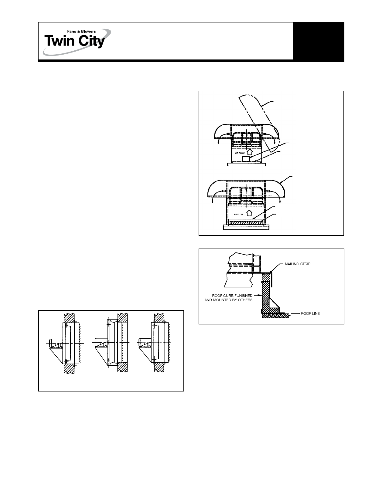
Figure 2. Typical Power Roof Ventilator
Installation Arrangements
HINGED HOOD
SIZE 12" – 42" ACCESS
DOOR FOR INSPECTION
SAFETY SCREEN STANDARD.
OPTIONAL DAMPER NOT SHOWN.
BOLTED HOOD
SIZE 48" – 60"
ACCESS DOOR FOR DAMPER
REMOVAL
OPTIONAL DAMPER
Figure 3. Mounting Roof Ventilator to Curb Cap
Installation
Panel Fans
Panel fans can be installed a number of different ways.
See Figure 1 for typical installation arrangements. If
dampers are used, they should be installed first. Then
the panel can be mounted and the motor wired.
Figure 1. Typical Panel Fan Installation Arrangements
RECESS SURFACE MOUNT SURFACE MOUNT
MOUNT WITH WALL BOX WITH ANGLE FRAME
Power Roof Ventilators
See Figure 2 for typical installation arrangements and
Figure 3 for mounting to curb cap.
Opening and Closing Hood
For sizes 12" – 42", a one-piece hinged hood is standard. To lift the hood, remove the two bolts located
under the mushroom cap and prop the hood up with
the supplied safety rods. Push and lock into place. A
screw is installed at the end of the pin side of the hinge
in the hood angle to prevent accidental removal of the
hood. To close the hood, replace the bolts to lock in
place.
For size 48", a one-piece bolted hood connects
directly to the fan stack. To lift the hood off the unit,
remove the bolts located under the mushroom cap.
For sizes 54"–72", a two-piece bolted hood connects
directly to the fan stack. To lift the hood off the unit,
remove the sheet metal bolts that connect the right and
left sides of the hood and then remove the bolts located under the mushroom cap.
Access To Dampers
A bolted access door is standard to provide access to
dampers.
Access To Wheel
Depending on fan size, wheels can either be removed
through the access door with the fan still mounted in
the hood or the fan can be lifted out of the unit and
the wheel removed.
Page 2

General Motor Maintenance
The three basic rules of motor maintenance are to keep
the motor (1) clean, (2) dry, and (3) properly lubricated.
Blow dust off periodically (with low pressure air) to prevent the motor from overheating.
Some smaller motors are lubricated for life. Motors
less than 10 HP running about eight hours a day in a
clean environment should be lubricated once every five
years; motors 15 to 40 HP, every 3 years; and motors
50 to 150 HP, yearly. For motors in dusty or dirty environments or running 24 hours a day, divide the service
interval by 2. If the environment is very dirty or high
temperatures exist, divide the service interval by 4.
Lubrication requirements are normally attached to the
motor. Do not over-lubricate.
Drive Maintenance
V-belt drives need periodic inspection and occasional
belt replacement. When inspecting drives, look for dirt
buildup, burrs or obstructions which can cause premature belt or drive replacement. If burrs are found, use
fine emery cloth or a stone to remove the burr. Be
careful that dust does not enter the bearings.
Check sheaves for wear. Excessive slippage of belts
on sheaves can cause wear and vibration. Replace worn
sheaves with new ones. Carefully align sheaves to avoid
premature sheave failure.
Observe belts for wear. If fraying or other wear is
observed to be mostly on one side of the belts, the
drives may be misaligned. Re-install the drives according
to the following instructions:
1. Slip (do not pound) the proper sheave onto the corresponding shaft. CAUTION: PLACING THE FAN
SHEAVE ON THE MOTOR CAN OVERSPEED THE
WHEEL AND CAUSE STRUCTURAL FAILURE.
2. Align sheaves with a straightedge extended along the
sheaves, just making contact in two places on the
outside perimeters of both sheaves.
3. Tighten down sheave bolts.
4. Install a matched set of bolts. Slide the motor to
obtain slack and tighten the belts. Using a pry will
damage the belts.
5. Tighten the belts to the proper belt tension. Ideal
tension is just enough tension so that belts do not
slip under peak load. Recheck sheave alignment.
6. After initial installation of the belts, recheck the belt
tension after a few days and adjust it if necessary.
(New belts require a break-in period of operation.)
Never use belt dressing on any belts.
Bearing Maintenance
Proper lubrication of belt drive bearings helps assure
maximum bearing life. All fans are equipped with decals
indicating relubrication intervals for normal operating
conditions. However, every installation is different and
the frequency of relubrication should be established
accordingly. Observation of the condition of the grease
expelled from the bearings at the time of relubrication
is the best guide as to whether regreasing intervals and
amount of grease added should be altered.
Greases are made with different bases. There are
synthetic base greases, lithium base, sodium base, etc.
Avoid mixing greases with different bases. They could
be incompatible and result in rapid deterioration or
breaking down of the grease.
All bearings are filled with lithium grease before leaving the factory. When the fans are started, the bearings
may discharge excess grease through the seals for a
short period of time. Do not replace the initial discharge
because leakage will cease when the excess grease has
worked out. The bearings may run hotter during this
period but temperatures should recede within 48
hours.
When relubricating, use a sufficient amount of grease
to purge the seals. Rotate bearings by hand during
relubrication.
Operation Checklist
Safety Precautions
□ Verify that proper safety precautions have been followed.
□ All electrical power is locked off.
Fan Mechanism Components Are Ready
□ Nuts, bolts and setscrews are tight.
□ Mounting connections are properly made and tight-
ened.
□ Bearings are properly lubricated.
□ Wheel, drives and fan surfaces are clean and free of
debris.
□ Rotating assembly turns freely by hand.
□ Drives are on correct shafts, properly aligned, and
properly tensioned.
Fan Electrical Components Are Ready
□ Motor is wired for proper supply voltage.
□ Motor was properly sized for power of rotating assem-
bly.
□ Motor is properly grounded.
□ All leads are properly insulated.
Trial “Bump”: Turn on power just long enough to start
assembly rotating.
□ Check rotation for agreement with rotation arrow.
□ Listen for any unusual noise.
□ Run unit up to speed.
□ Bearing temperatures are acceptable after one to two
hours of operation (< 150°F).
□ Vibration levels are acceptable.
After One Week of Operation
□ Check all nuts, bolts and setscrews and retighten if
necessary.
□ Readjust drive tension if necessary.
Twin ciTy fan & blower | www.Tcf.com
5959 Trenton Lane N | Minneapolis, MN 55442 | Phone: 763-551-7600 | Fax: 763-551-7601
1MSS8/10
 Loading...