

Twin City ES-110 User Manual
MPQN/MPQS Modular Plenum Fans
INSTALLATION, OPERATION & MAINTENANCE MANUAL
ES-110
February 2012
Contents
Introduction .........................................................................1
Shipping and Receiving .....................................................1
Handling .............................................................................. 1
Short Term Storage ...........................................................1
Long Term Storage............................................................1
Foundations and Supporting Structures .......................... 2
Fan Installation ...................................................................3
Assembly of Fans and Sealing/Isolation Strips ..............3
Fan Operation – Safety .....................................................3
Operation Checklist ............................................................ 4
Maintenance of Fans ......................................................... 4
General Motor Maintenance ......................................... 4
Wheel and Shaft Maintenance ..................................... 5
Structural Maintenance ................................................. 5
Troubleshooting Guidelines................................................ 5
Troubleshooting Performance Problems
Air Capacity Problems ..................................................5
Noise Problems .............................................................5
Vibration Problems ........................................................ 5
Motor Problems ............................................................. 5
Limitation of Warranties and Claims ............................... 6
Introduction
The purpose of this manual is to provide instructions
that complement good general practices when installing or operating fans manufactured by Twin City Fan &
Blower. It is the responsibility of the purchaser to provide qualified personnel experienced in the installation,
operation, and maintenance of air moving equipment.
Instructions given in the body of this manual are general in nature and apply to a variety of models manufactured by Twin City Fan & Blower. Most units can be
installed and maintained with the instructions given.
Special applications may require additional information.
These instructions are supplied in the form of attached
appendices. Use the instructions in the appendix if the directions in this manual differ from instructions in the appendix.
As always, follow good safety practices when installing, maintaining and operating your air moving equipment. A variety of safety devices are available. It is
the user’s responsibility to determine adequate safety
measures and to obtain the required safety equipment.
Handling
Handling of all air moving equipment should be conducted by trained personnel and be consistent with safe
handling practices. Verify the lift capacity and operating condition of handling equipment. Maintain handling
equipment to avoid serious personal injury.
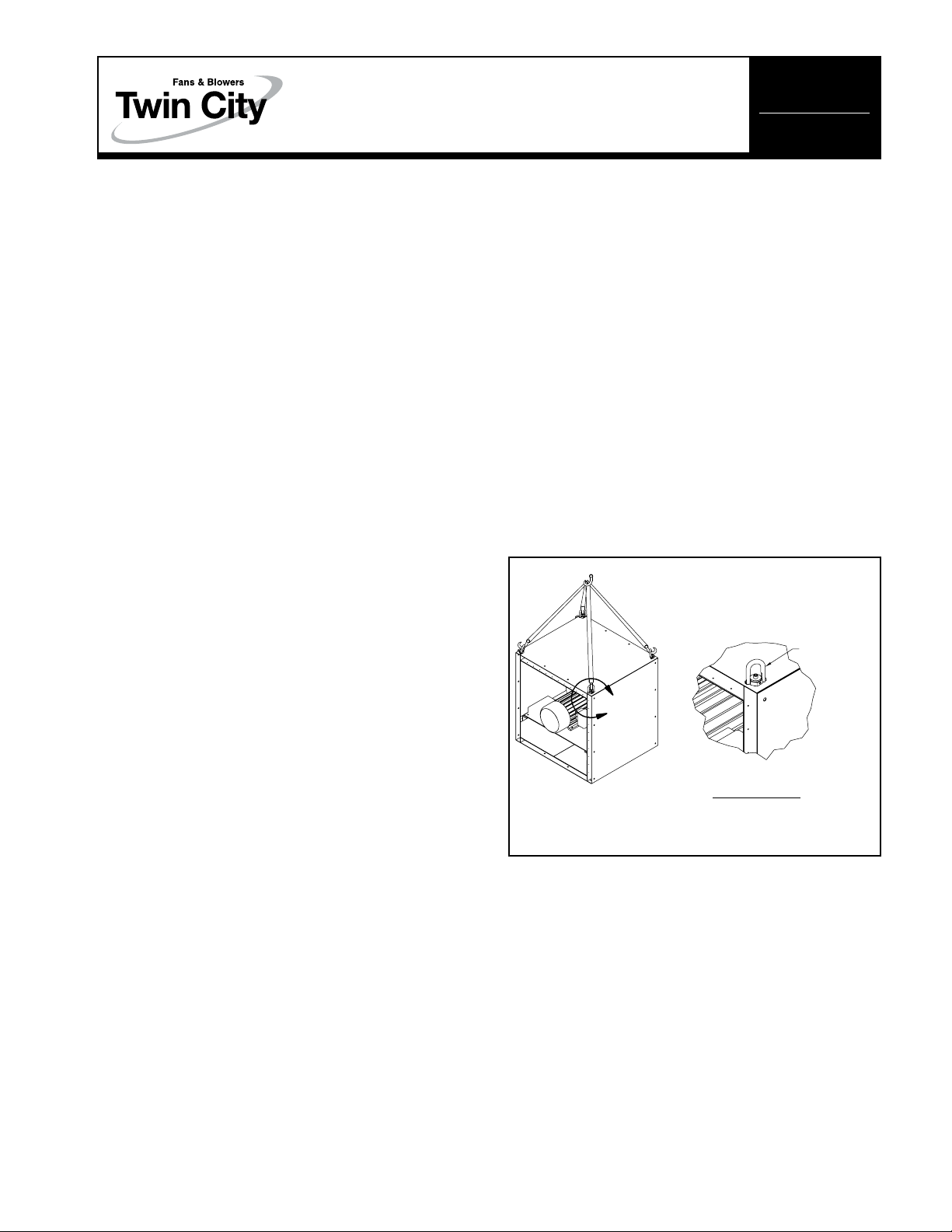
Units shipped completely assembled may be lifted with
slings and spreader bars. Use well-padded chains, cables
or nylon straps. On most units, lifting lugs are provided
for attaching chains (see Figure 1). Lift the fan in a fashion that protects the fan and fan coating from damage.
Never lift a fan by the inlet or discharge flange, shafting
or drives, wheel or impeller, motor or motor base, or in
any other manner that may bend or distort parts.
Partial or disassembled units require special handling.
All parts should be handled in a fashion which protects the coatings and parts from damage. Components
should be handled such that forces are not concentrated
and bending or distortion cannot occur.
Figure 1. Lifting Lug Locations
SWIVEL
EYE HOOK
(By Customer)
A
DETAIL A
NOTE: When lifting, the straps/chains
should be at a minimum angle of 45
Housing should be lifted using straps and spreaders.
Do not distort housing or side plates when lifting.
o
Shipping and Receiving
All Twin City Fan & Blower products are carefully constructed and inspected before shipment to insure the
highest standards of quality and performance.
Compare all components with the bill of lading or
packing list to verify that the proper unit was received.
Check each unit for any damage that may have
occurred in transit. Any damage should be reported
immediately to the carrier and the necessary damage
report filed.
©2012 Twin City Fan Companies, Ltd.
Short Term Storage
If fan installation is to be delayed, store the unit in a
protected area. Protect the fan and motor bearings from
moisture and vibration (or shock loading).
Long Term Storage
Prior to Storage – Motor bearings are to be greased at
the time of going into extended storage per the motor
manufacturer’s specifications.

Storage Procedure – Fans should be stored indoors
whenever possible where control over temperature,
shock and dust is reasonably maintained. If units are to
be stored outside in the elements, they should be covered with a water-resistant material. Stored equipment
should be stored on a clean, dry floor or blocked up
off the ground on blocks to prevent unit from setting in
any water or directly on the ground. If shock or vibration
will be present during storage, the unit may need to be
placed on some type of vibration dampening material to
aid in preventing brinelling of the bearing surfaces.
Periodic Check – On a monthly interval, the equipment
should be checked to ensure that it has remained in
an acceptable stored condition. The fan wheel should
be rotated several times by hand while adding enough
grease to replenish the bearing surfaces with fresh
grease and to maintain a full bearing cavity. Grease
used must be compatible with that already supplied in
the motor and fan bearings. The fan impeller should
be left at approximately 180 degrees from that of the
previous month to prevent the shaft and impeller from
taking a set in one position. Storage records should
be maintained which indicate the above requirements
have been followed. Consult the motor manufacturer for
proper storage, space heater connection and lubrication
if the unit was supplied with one.
Start-Up – When the unit is removed from storage, all
bearing grease should be purged and replenished with
fresh grease as per the lubrication decal. The motor
should be measured to verify that the resistance is still
at a satisfactory level compared to the value recorded
prior to storage.
Foundations and Supporting Structures
Floor mounted fans should be installed on a flat, level
surface with sufficient structure support. Support shall
be suitable for static and dynamic loads and foundation
frequencies be separated at least 20% from the rotational speed/speed ranges.
If the fans are mounted on a sub-structure, an inertia
base with spring isolator system should be considered.
Fans mounted to or within a structure should be
placed as close as possible to a rigid member such
as a wall or column. The structure must be designed
for rotating equipment; static design for strength is
not sufficient to insure proper operation. Supports for
suspended fans must be cross-braced to prevent side
sway. Structural resonance should be at least 20% from
fan operating speed.
Any ducting and/or dampers with sleeves should have
independent support; do not use the fan for support.
Isolating the fan from ductwork with flex connections
eliminates transmission of vibration.
1. Sufficient structure must be provided to support
weight of fan assembly.
2. Sufficient restraint must be provided to resist the
pressure force against the fans. Typically fans are
assembled in an application in a modular fashion with
multiple fans working in parallel. The cumulative thrust
force must be restrained to prevent the fan assemblies
from leaning or tipping forward. The force acting on
the fan assemblies is calculated as shown below.
Thrust force (lb
27.68
H x W x N x P
f) =
s
Where
P
s = Maximum operating static pressure (in. w.g.)
W = Width of each individual fan (in.)
H = Height of each individual fan (in.)
N = Quantity of fans in system
27.68 = conversion factor for in. w.g. to PSI
Example
Parallel fan system employing nine (9) – Size 182 fans
in a 3 x 3 configuration. (3 fans high x 3 fans wide)
System pressure is 5 inches of water column.
Outside dimension of fan housing = approx. 32 in. by
32 in.
Thrust force (lb
27.68
Thrust force (lb
27.68
Note: The thrust force is distributed evenly across the front
surface of the parallel fan system.
H x W x N x P
f) =
32 x 32 x 9 x 5
f) =
s
= 1665 (lbf)
3. Recommend attachments to the sides and top of the
parallel fan system incorporating some form of spring
support, i.e. rubber snubbers/isolators or springs. Such
devices should be attached to prevent significant point
loading on an individual fan. They should be located
on the side of the parallel fan system at the top corner and along the top every 2 fans or less.
a. When the fans are rigidly mounted to the base, an
assumption can be made that half of the thrust
load will be supported at the base, and the supports added at the top of the fan need to carry a
minimum of one half of the thrust load.
b. When the fans are supported on an isolation base
or isolators, it will be necessary to add thrust
restraints around the periphery of the fan assembly
to support the entire thrust load. Flex connections are required when using isolators or isolation
base.
c. Attachments to the fan can be made utilizing the
factory mounting holes. Recommend that the gage
of the materials be checked for tear out strength
in thrust applications. If necessary utilize multiple
mounting hole locations to distribute the load.
2
Twin City Engineering Supplement ES-110
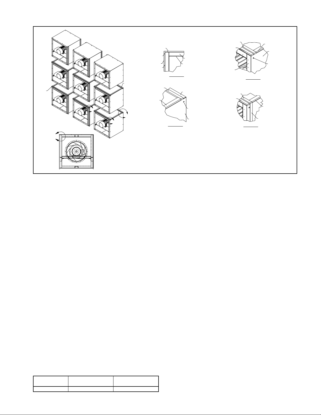
Figure 2.
RUBBER GASKET
NOTE 5
RUBBER GASKET
OUTER SHELL
RUBBER GASKET
NOTES
D
B
A
RUBBER GASKET
RUBBER GASKET
C
NOTES:
1. On the horizontal between fans, one strip of gasket material is needed on inlet side & two
on drive end on 222 & above, 200 and below get one strip on each end.
2. Gaskets need to connect in all corners to ensure proper sealing.
3. Rubber gasket is to be placed directly next to the mounting holes on the inlet and drive side.
4. Rubber gasket is 1/2 in. x 2 in. x cut-to-fit.
5. Rubber gasket is to be held in place be double-stick foam tape during assembly.
Fan Installation – Factory Assembled Units
Follow proper handling instructions given earlier.
1. Move the fan to the final mounting position.
2. Remove skid, crates, and packing materials carefully.
3. If supplied, place vibration pads or isolation base on
mounting bolts. Line up holes in fan base with bolts.
4. Place fan on mounting structure. Carefully level unit
using shims as required at all mounting hole locations. Bolt down the unit.
Assembly of Fans and Sealing/Isolation
Strips
1. Fans must be securely bolted to a base either directly
through the factory mounting holes or with a properly
designed clip. Final bolting of layer of fans to the
support structure or base should be done after the
individual fans are bolted together as a row.
2. During installation rubber strips need to be installed
between each fan. Use double-sided foam tape to
hold strips in place during installation. Two (2) to
three (3) pieces of tape can be used as needed for
this purpose (each end and middle of rubber strip).
Location of these strips is documented in Figure 2.
3. The first fan on the bottom row will have the 2 vertical strips placed next to the mounting holes. Note:
Strips should be cut to ensure an airtight seal between
fans.
4. The bolts to be snugged up on vertical sections for the
first row. Once all strips are in place, the bolts shall
be tightened to torque values in table. See Table 1.
Table 1. Torque Values MPQN/MPQS Fasteners
Size
3/8 – 16 UNC
Net Type
Nylock 16 – 17
Torque Values
(ft lbs)
DETAIL A
DETAIL C
FRAME
PERF. PLATE
OUTER SHELL
MOUNTING HOLE
OUTER SHELL
RUBBER GASKET
RUBBER GASKET
OUTLET ONLY
222 & ABOVE
FRAME
RUBBER GASKET
RUBBER GASKET
DETAIL B
DETAIL D
RUBBER GASKET
OUTER SHELL
MOUNTING HOLE
RUBBER GASKET
RUBBER GASKET
5. The bolts holding the fan to the supporting structure
can now be torqued.
6. Rubber strips are then placed on the top of the fan
to support the fan above it according to the pattern
shown. Note: On larger fan assemblies 2 strips are
used in the back to support the weight of the motor.
7. The second row and succeeding rows can be installed
using the same assembly steps as the first row.
8. Rubber strips are not normally needed on the outside
or top of the parralel fan system.
9. Sealing around the perimeter should be accomplished
using a flexible material.
Fan Operation - Safety
For general safety practices for air moving equipment,
see AMCA Bulletin 410.
Twin City Fan & Blower has many safety accessories available. These safety devices include (but are not
limited to) inlet and discharge screens. The use, abuse,
or non-use of safety devices is the responsibility of the
purchaser.
Facility-related safety conditions include fan accessibility and location. How easily can non-service personnel access the unit? Is the fan in a hazardous duty
environment? Was the unit ordered for this duty? Other
concerns must also be addressed. All fans should be
powered through switches which are easily accessible to
service personnel from the fan. Every switch should have
the ability to be “locked-off” by the service person and
the key to be retained by this person to prevent accidental power of the fan while service is in process.
3
Twin City Engineering Supplement ES-110
 Loading...