

twin busch TW 125 M, TW 125 F, TW 125 M Ultra Installation, Operation And Maintenance Manual
Page 1
Page 2

Printing errors, mistakes and technical changes reserved.
V01.NK.618_EN
© by Twin Busch Germany GmbH 2
Page 3

INDEX
1. Notes and safety notes 4 - 6
1.1 Important note
1.2 Specialist
1.3 Safety notes
1.4 general notes
1.5 Warning notes
1.6 Loudness
1.7 Training
2. Overview 7 - 8
2.1 General description
2.2 Technical data
2.3 Construction of the lift
3. Mounting the Lift 9 - 12
3.1 set the Limit switch
3.2 Power supply
3.3 Oil connection
3.4 TW 125 F
3.5 Checkpoints after the Installation
4. Operating instructions 13
4.1 mechanical instructions
4.2 Electrical instructions
5. Operating 14 - 17
5.1 How to operate
6. Maintenance 18
6.1 Daily check
6.2 Monthly check
6.3 maintenance interval
6.4 Troubleshooting
6.5 General notes
7. Annex 19 - 38
7.1 Technical data sheet
7.2 Dimensions / TW 125 M Ultra flat
7.3 Dimensions / TW 125 F
7.4 Electrical diagram
7.5 Hydraulic diagram
7.6 24V- Electrical diagram
7.7 Spare parts
Printing errors, mistakes and technical changes reserved.
V01.NK.618_EN
© by Twin Busch Germany GmbH 3
Page 4

1. Notes and Safety notes
1.1 important notes
Neither the manufacturer nor the seller will accept liability for improper installation, improper operation, overloading or
unsuitable ground conditions.
This model is specifically designed for lifting motor vehicles that do not exceed the approved maximum weight. If the lift is used
for other purposes, neither the manufacturer nor the seller will be liable for any accidents or damage.
Pay special attention to the permitted maximum weight. A sign with the approved maximum weight is attached to the lift. Never
try to drive vehicles that exceed the approved maximum weight
lift with the lift.
Read the operating instructions carefully before operating the lift in order to avoid damage due to personal negligence.
1.2 Specialist
1.2.1 Only trained person are allowed to use the lift.
1.2.2 Electrical installation has to be done by an electrical specialist.
1.2.3 Costumer or other people are not allowed in the neat of the lift during operation.
1.3 Safety notes
1.3.1 Never move the lift when a vehicle is lifted up.
1.3.2 The engine has to be shot off during the operation.
1.3.3 The lift may only be put into operation if the vehicle is properly aligned.
Only lift the vehicle in the place approved by the manufacturer and make sure that the transport mechanism is secured
(release the pressure so that the lift rests firmly on the ground).
Check the secure locking of the support arm lock and, if necessary, engage it in a renewed manner to ensure that the
support arms can´t move.
1.3.4 It is forbidden to use the lifting arms of the lift as a storage area, especially for highly flammable or corrosive liquid.
1.3.5 Never use the Lift like a fork lifter.
1.3.6 All cables must be free of obstacles. Nothing should put pressure on the lines.
1.3.7 The area around the lift has to be free.
1.3.8 Do not use the lift in a washing bay.
1.3.9 It is prohibited to exceed the maximum stated lifting weight, (maximum lifting weight is 2500 kg) or lifting vehicles with
more than 2900 mm wheelbase.
1.3.10 never stands on top of the lift or climb on it.
Attention! Any other use of the lift is improper and inappropriate. The manufacturer is not liable for any damage resulting from
using the machine for any purpose other than that stated in this manual.
1.3.11 to protect the operator, this lift is equipped with several safety devices in the electrical and mechanical system.
1.3.12 this lift is made only for lifting up vehicles.
1.3.13 The TW 125 M Ultra flat single-column lift is suitable for outdoor use (in dry weather only) as it is classified as a
mobile hoist.
Printing errors, mistakes and technical changes reserved.
V01.NK.618_EN
© by Twin Busch Germany GmbH 4
Page 5
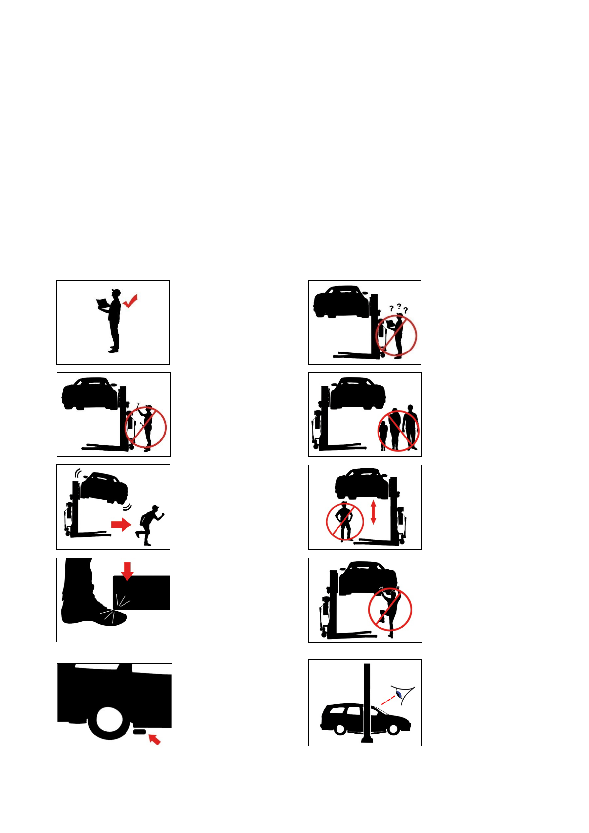
Read the manual
Only trained person are
allowed to use the lift
Repairs and maintenance
only by qualified
personnel never put
safety equipment out of
operation!
Keep the working area
clear
Always keep escape
routes clear!
The presence of persons
(when lifting or lowering)
under the lift is prohibited!
Watch your feeds
Climbing the lift is strictly
prohibited!
Observe the pickup points
of the vehicle
manufacturer!
After a short lifting, check
the vehicle for a secure fit!
1.4 General Description
Working place
TW 125 M Ultra: This lift can also be used outdoors on sunny, dry days with a suitable paved surface. However, it is expressly
recommended by the manufacturer to use the lift in closed and dry rooms to protect the electric drives and controls.
Power supply
230 V (standard delivery), 400 V / 3 phases on request.
Working environment
You should ensure at least 1 m of free space around the lifted vehicle and around the lift,
and have a ceiling height of at least 3.6 m.
1.5 Safety notes
All warnings are clearly visible on the lift to ensure that the user uses the device in a safe and secure manner. The warnings
must be kept clean and replaced if they are damaged or missing.
Please read the signs carefully and memorize their meaning for future operations.
Printing errors, mistakes and technical changes reserved.
V01.NK.618_EN
© by Twin Busch Germany GmbH 5
Page 6
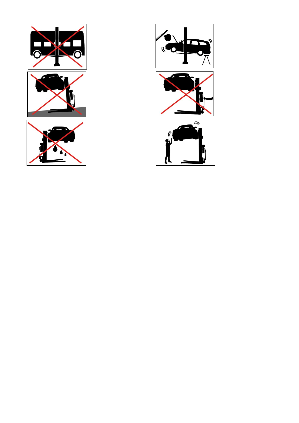
The specified load
capacity
When installing or
removing heavy parts, the
vehicle can tip over!
Support the vehicle!
Use only on level ground!
Do not maneuver with the
vehicle raised!
Protect the lift from
moisture!
Electrical connections
must be absolutely dry!
Avoid strong shaking on
the vehicle!
1.6 Loudness
The emitted noise should not exceed 75 dB.
1.7 Training
Only qualified personnel may operate the lift. If necessary, we offer professional training for users.
Printing errors, mistakes and technical changes reserved.
V01.NK.618_EN
© by Twin Busch Germany GmbH 6
Page 7
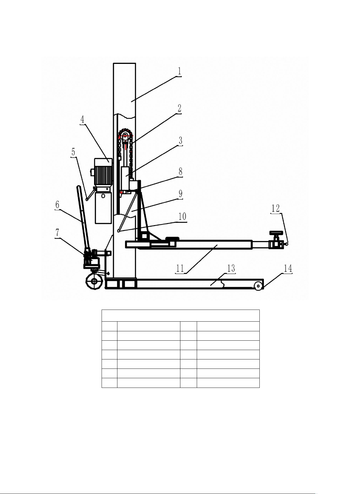
2. Overview
name
1
Vertical Colum
8
Safety components
2
chain
9
Lifting slet
3
Hydraulic cylinder
10
Safety components
4
Motor
11
Main arm
5
Discharge handle
12
Safety handle
6
Handle
13
Base frame
7
Hydraulic wheel
14
wheel
Printing errors, mistakes and technical changes reserved.
V01.NK.618_EN
© by Twin Busch Germany GmbH 7
Page 8
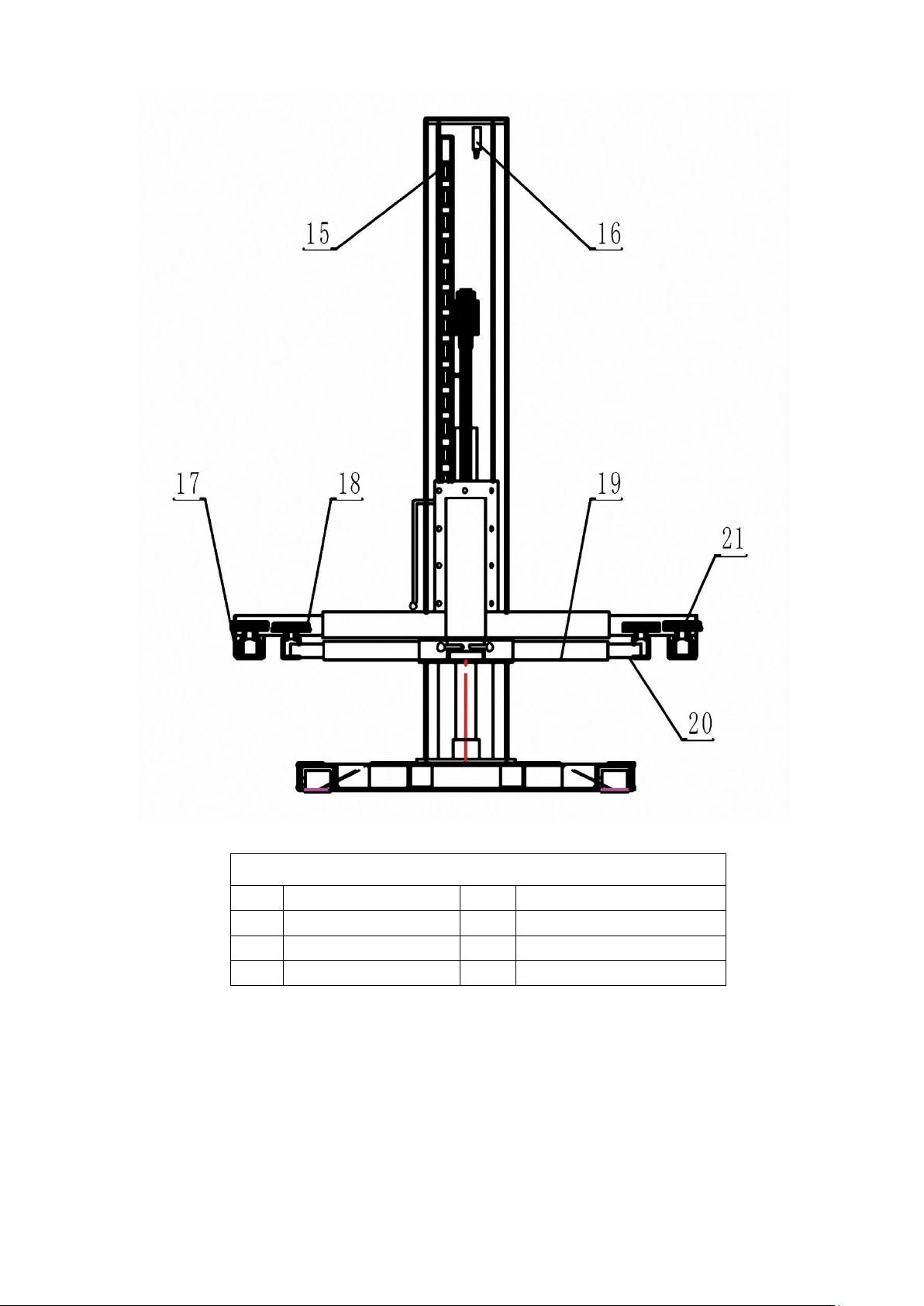
name
15
Safety rack
19
Lifting arm
16
Limit switch
20
Extension arm
17
Extension arm
21
plate
18
Lifting arm
Printing errors, mistakes and technical changes reserved.
V01.NK.618_EN
© by Twin Busch Germany GmbH 8
Page 9
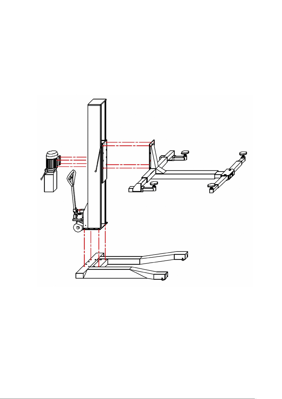
3. Assembly
DIN 933 4.8 M10x30
Torque 12 Nm +/- 5 Nm
DIN 933 8.8 M16x40 Torque 200 Nm +/- 10 Nm
Printing errors, mistakes and technical changes reserved.
V01.NK.618_EN
© by Twin Busch Germany GmbH 9
Page 10
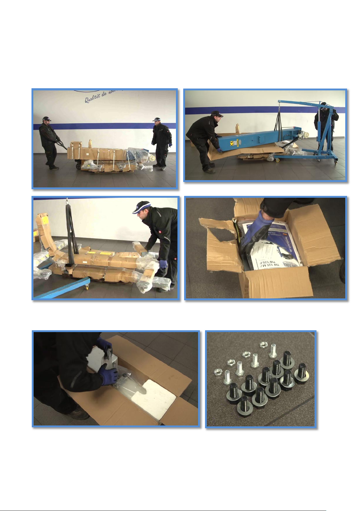
Preparation of the assembly
The TW 125 M 1-post lift is delivered on a single pallet.
In our case, 2 people build the 1-column lifting bales with the help of a motor crane.
If you do not have a motor crane or another suitable lifting device available, we recommend that you use a sufficient number of
strong people for the bodywork. First remove the box with the control unit.
Please read carefully the instructions in the box with the control unit before further assembly.
Then remove the box with the motor unit. In this there is a bag with the mounting screws.
•
Now we can remove the outer packaging.
Printing errors, mistakes and technical changes reserved.
V01.NK.618_EN
© by Twin Busch Germany GmbH 10
Page 11
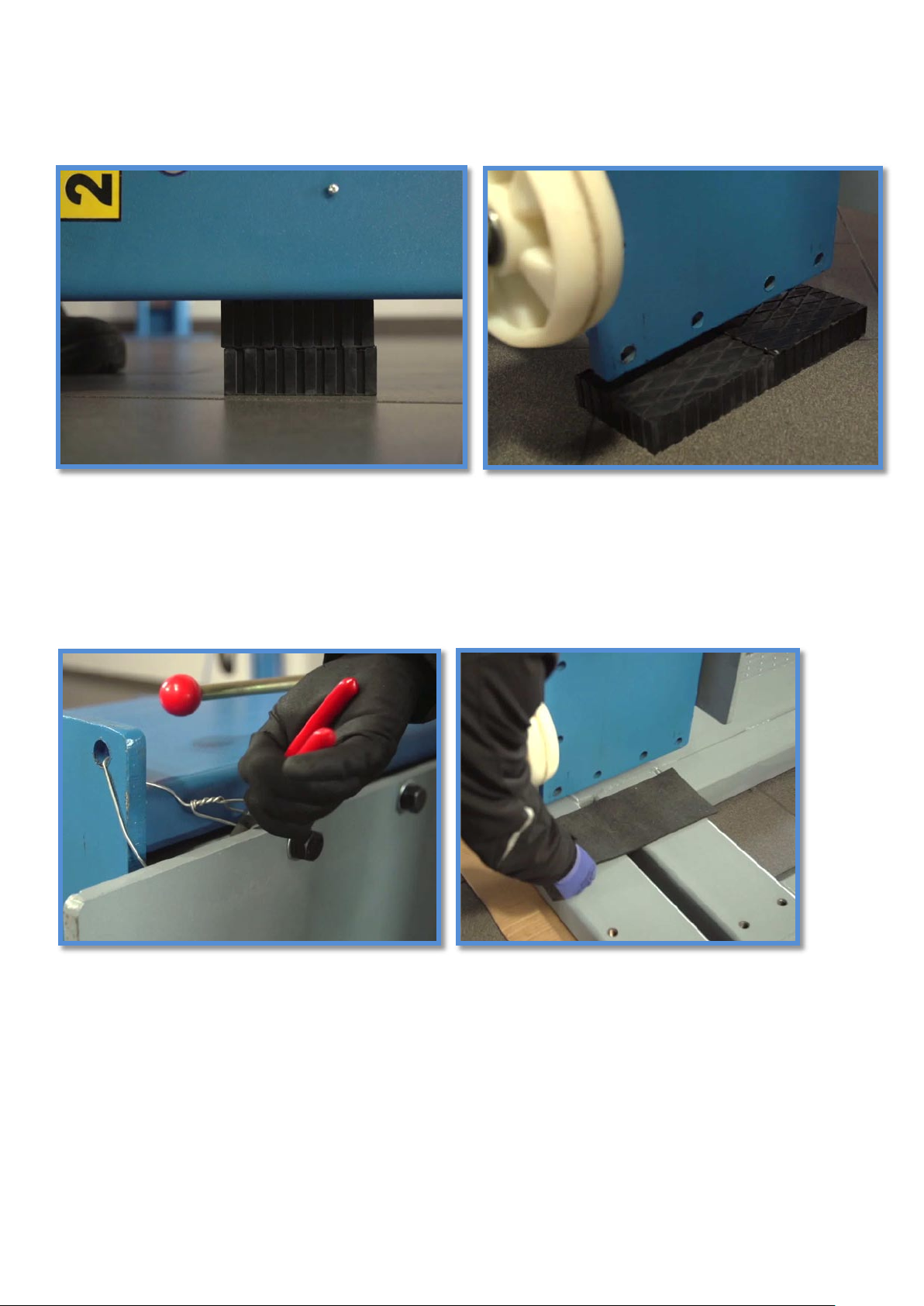
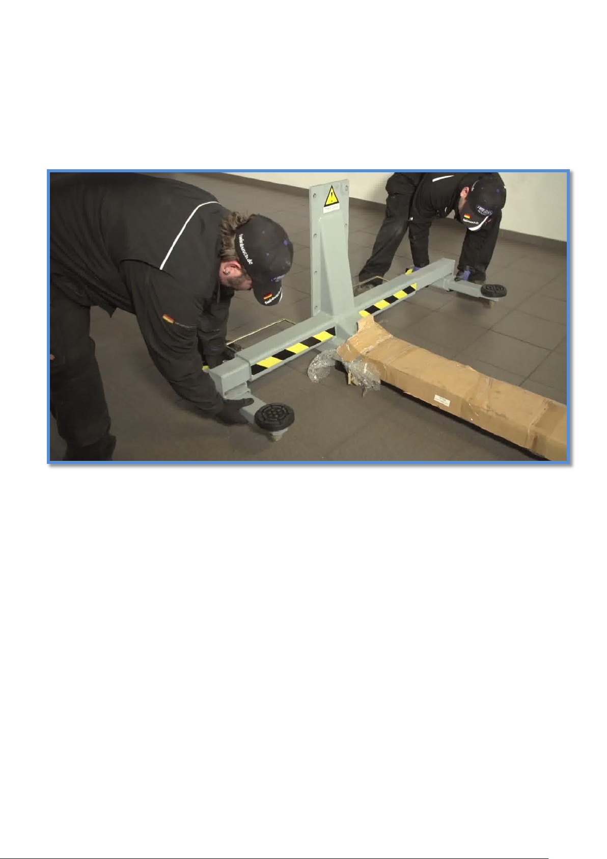
Next we use the motor crane to put the column aside. To remove the pillar, it must be turned slightly on the ground.
(Put something under it during draining so that the floor is not scratched)
Now the column can be placed on rubber blocks or another suitable substructure.
Next we lift the support arm unit off the package.
Place a sling as shown here around the support arm assembly. Now the arm unit can
be put on the edge.
We are also underlain here with rubber blocks, since next the sling for further transport must be moved further towards the
center. Now the support arm unit can be moved aside. We only need them again at the very end of the construction.
Again, we are inferior, so we can easily remove the strap and not scratch the floor.
Printing errors, mistakes and technical changes reserved.
V01.NK.618_EN
© by Twin Busch Germany GmbH 1 1
Page 12
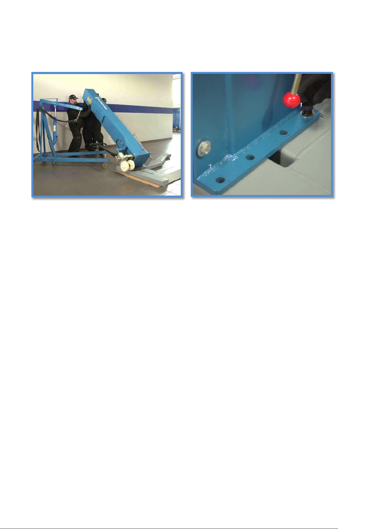
In the next step we put the pillar on the stand foot. Now we still have to cut the wire, to do this, the column is raised again to
align with the engine crane.
Align the column so that the holes will overlap each other after erecting the column. Again, we put something down. A thin piece
of rubber is optimal.
For your safety, we recommend that you set up with at least three strong people.
Make sure that the column can´t tip over accidentally and fix it immediately with the 10 supplied screws.
Printing errors, mistakes and technical changes reserved.
V01.NK.618_EN
© by Twin Busch Germany GmbH 12
Page 13
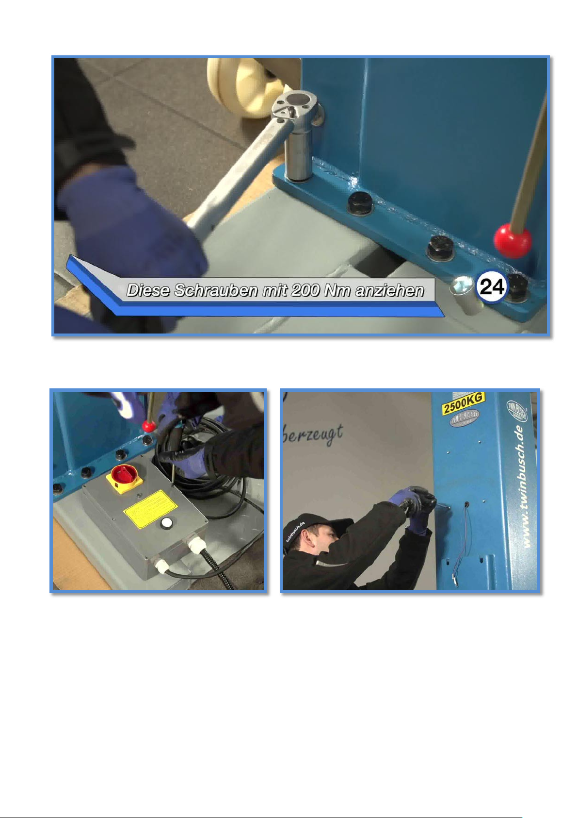
Remove the control unit from the box and unscrew it.
The screws for mounting the control unit are preassembled on the column.
Printing errors, mistakes and technical changes reserved.
V01.NK.618_EN
© by Twin Busch Germany GmbH 13
Page 14
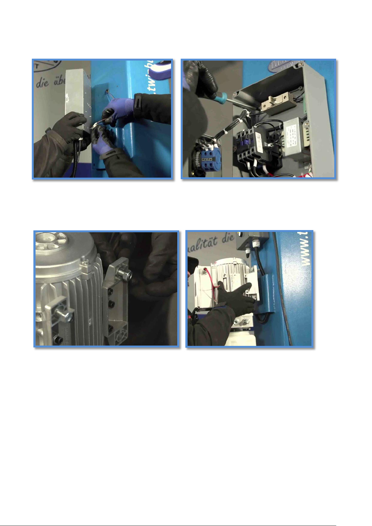
Please note that the following electrical installation may only be carried out by a qualified
electrician!
Now the motor cable can be connected.
To do this, we first open the box on the motor unit.
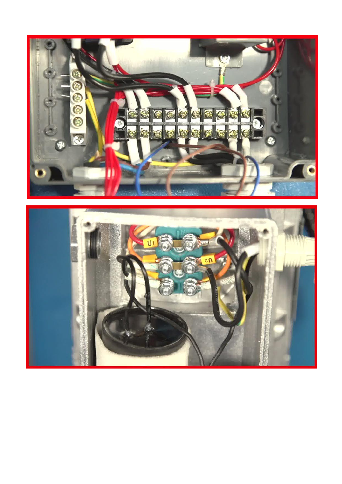
There we open the two upper right terminals to which the red test leads are connected.
Remove the red test leads from the box, but remember exactly where they were connected.
Printing errors, mistakes and technical changes reserved.
V01.NK.618_EN
© by Twin Busch Germany GmbH 14
Page 15
Next, the oil hose is screwed on.
First tighten the connection to the motor unit.
To screw the oil hose, we hold the hose in position so that it runs straight down after tightening.
Screw the hose tight.
Printing errors, mistakes and technical changes reserved.
V01.NK.618_EN
© by Twin Busch Germany GmbH 15
Page 16
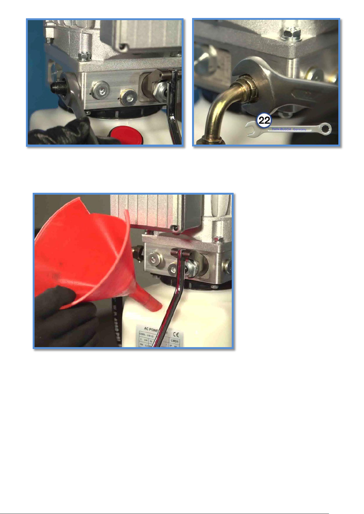
Let's fill up the oil tank (10 liters of hydraulic oil).
However, by no means more than the MAX marks.
Then we close the tank well again.
Printing errors, mistakes and technical changes reserved.
V01.NK.618_EN
© by Twin Busch Germany GmbH 16
Page 17
Printing errors, mistakes and technical changes reserved.
V01.NK.618_EN
© by Twin Busch Germany GmbH 17
Page 18
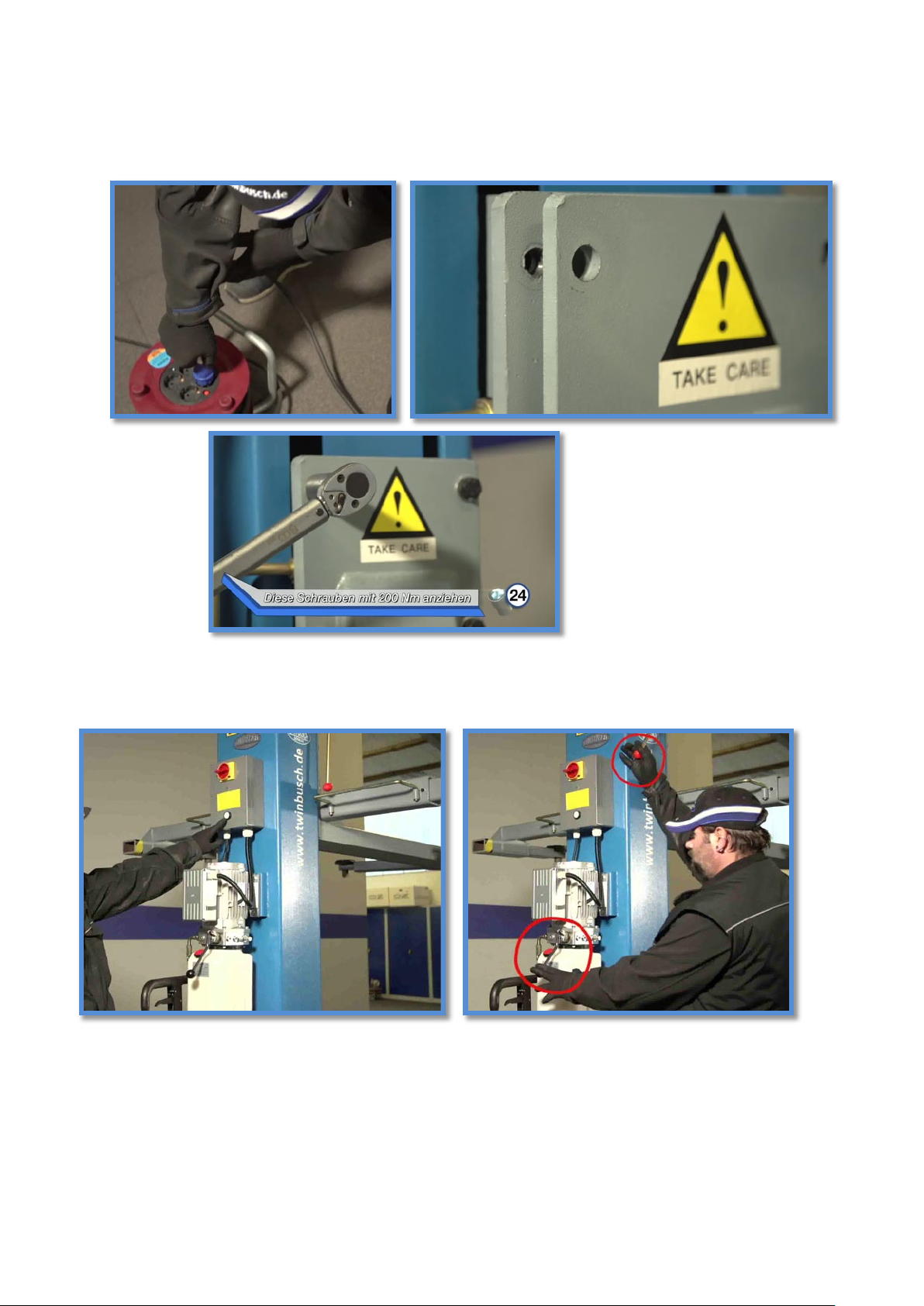
Now we connect the lift to the power to lift the lift easily for further assembly. Press the button on the control unit until the lift is at
the same height as the support arm unit.
Should you drive too far, you can lower the lifting carriage via the release lever. Then the previously unscrewed screws are
reinstalled.
These screws must be tightened with a torque of also 200 Newton meters crosswise.
Thus, the assembly is almost complete.
Printing errors, mistakes and technical changes reserved.
V01.NK.618_EN
© by Twin Busch Germany GmbH 18
Page 19
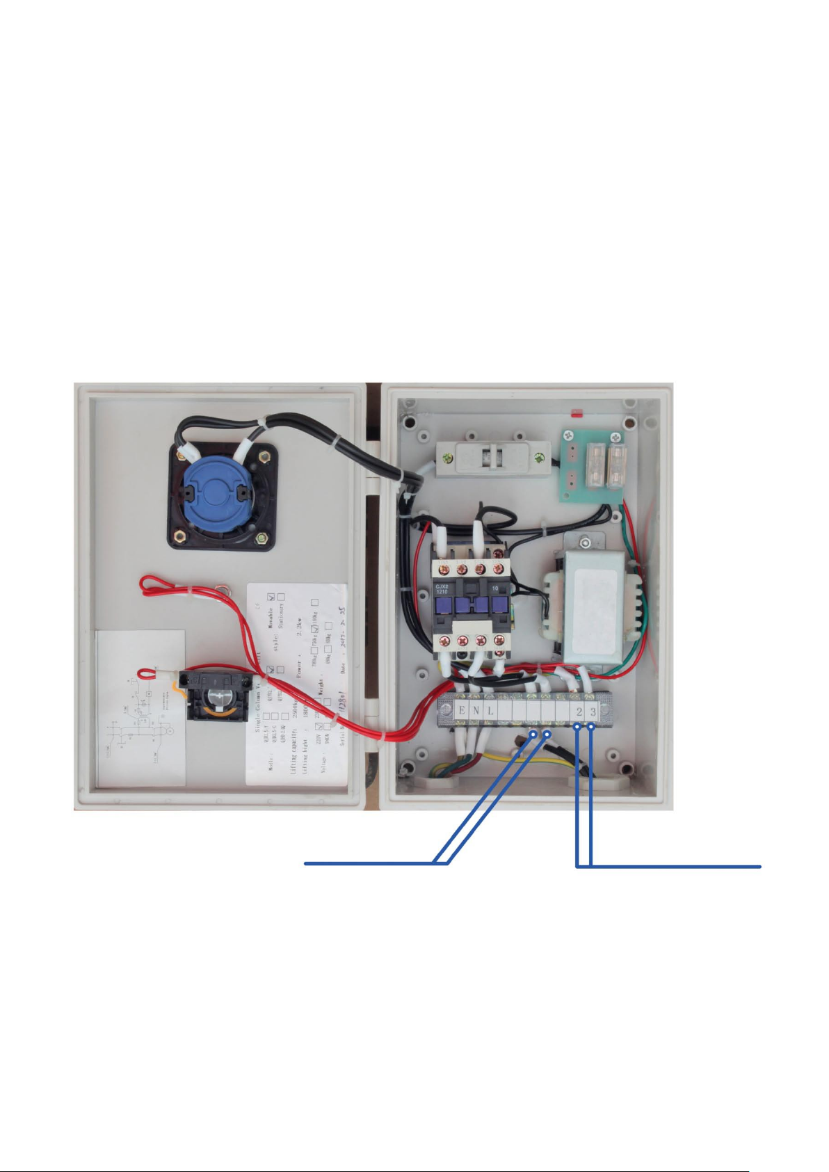
Wire from Motor
Limit switch
Let's go up the stage a bit to remove the remaining packaging.
At the end we only need one more test run.
Drive the stage all the way to the top and test the limit switch.
After the limit switch has successfully stopped the stage automatically, they can use the drain lever on the motor unit to place
the stage in the top safety catch.
To deflate the stage must first be moved out of the safety catch a bit, and then by simultaneously pressing the release and
release lever to be drained.
This completes the assembly of your single column lift.
3.1 Limit Switch
Connect the wire from the limit switch on point 2 and 3 like in the follow picture.
Printing errors, mistakes and technical changes reserved.
V01.NK.618_EN
© by Twin Busch Germany GmbH 19
Page 20
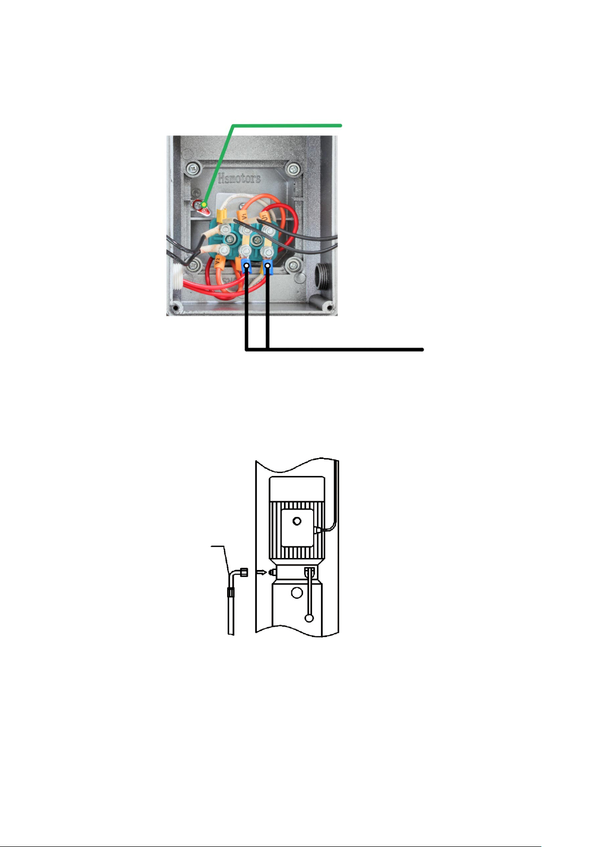
3.2 Power supply
Replace two red test lines by black
power lines.
(PE) Ye/gr
Fill up the tank (10 L) to 80 %
(oil - HLP 32)
Oil hoses
Connect power lines from the control box in the junction box of the motor.
3.3 Connect the oil hoses
Printing errors, mistakes and technical changes reserved.
V01.NK.618_EN
© by Twin Busch Germany GmbH 20
Page 21
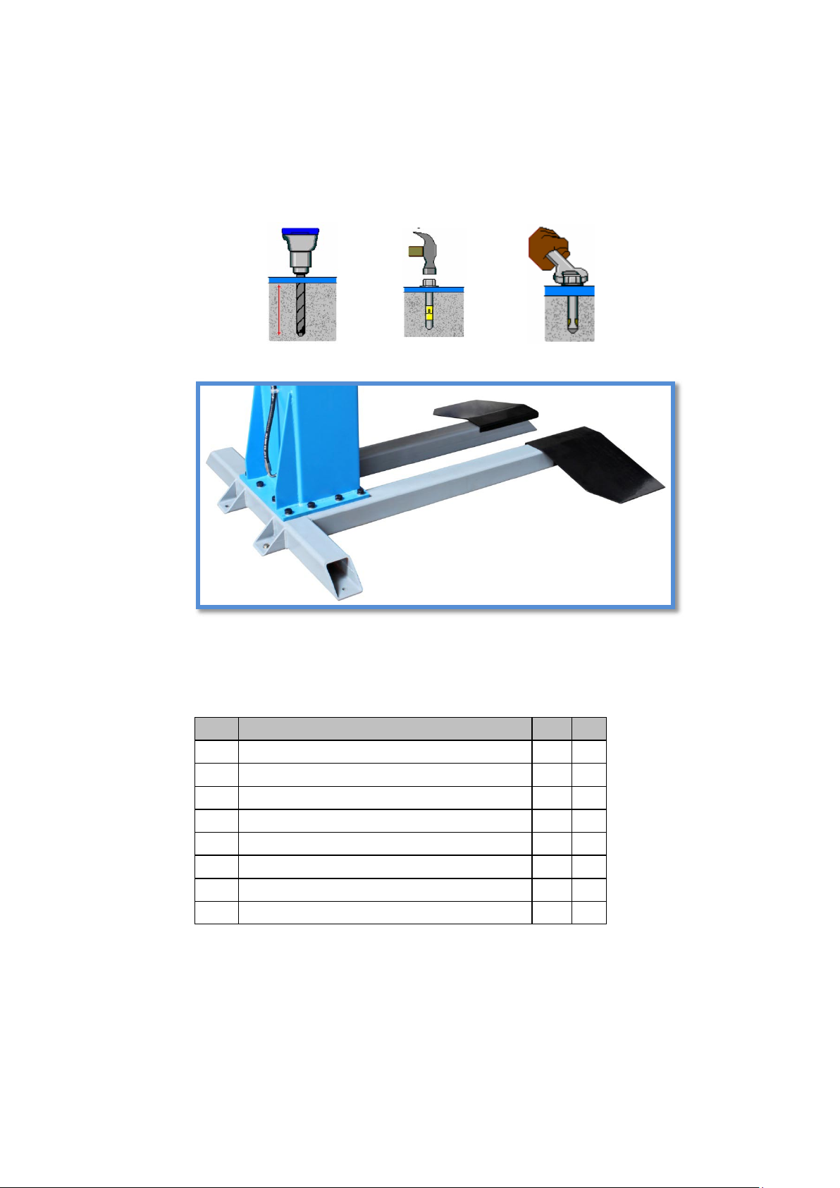
3.4 TW 125 F Floor mounting
S/N
items
Y e s
No
1
Is the Floor aligning?
2
Are the screws closed? (90 Nm)
3
Are the oil hoses connected?
4
Are the Colum and the Base mounted? (200 Nm)
5 Are the arms mounted?
6
Is the electrical installation correct?
7
Are the safety components mounted?
8
Are all parts lubricated?
Align the base plate with a spirit level.
1. Drill the holes.
2. Clean the holes with a vacuum cleaner.
3.5 Checkpoints after the installing
Printing errors, mistakes and technical changes reserved.
V01.NK.618_EN
© by Twin Busch Germany GmbH 21
Page 22

4. Operation instruction
4.1 Operating instructions for the mechanical operation
This mobile lift is equipped with a separate transport mechanism that works like a lift truck. Move the steering handle up and
down several times until the lift is far enough away from the ground
has to move around you freely. When you have reached your desired location,
release the lift using the pressure release handle.
Before pushing the lift under a motor vehicle, make sure that both arms are aligned and without obstacles.
Lift the vehicle only at the points approved by the manufacturer.
The transport wheel on the column is retracted, make sure that no tools, screws,
small stones or other lying under the lift. It is strictly forbidden to start the lifting process
before the lift sits on the floor.
4.2 Operating the lift switch / operating test
Under no circumstances should you try to operate the lift before you have tested it.
This step is very important and necessary to ensure that all hoses are properly fastened and that there is no danger from any
leaking pipe.
Turn on the power at the rotary switch. Press the button / lift switch (under the on / off rotary switch) for about 2-3 seconds. The
lifting arms should now be raised, if this is not the case you must make sure that the power supply is correctly connected.
Connect them correctly so that the direction of rotation of the motor is correct (400 V version).
Printing errors, mistakes and technical changes reserved.
V01.NK.618_EN
© by Twin Busch Germany GmbH 22
Page 23

5.
Operation (using the mobile lift with manual unlocking as an example)
1. Position the vehicle to be serviced and switch off the engine.
2. Lift the lift by moving it up and down (lift truck principle) of the swiveling handle
(Steering arm) light on.
3. Slide the lift under the vehicle. (Alternatively, you can drive onto the lift,
if it was previously drained and sits firmly on the ground).
4. Make sure that the floor meets the requirements, is level and no obstacles
located on the ground.
5. Operate the pressure release handle on the swivel handle to release the lift.
The lift must be firmly on the ground.
6. Align the lift so that the lifting points on the vehicle and the lift coincide.
7. Press and hold the lift button (under the on / off switch) until the car is raised about 10-15 cm.
8. Now stop the lifting process and make sure that the car is correctly and safely aligned.
9. Lift the vehicle only at the points approved by the manufacturer.
10. If you wish to release the lift for corrective action, press and hold the unlocking lever (release the safety catch)
while pressing the release lever
at the lift.
11. To change the height of the mounting plates, turn them.
12. After final alignment and check on firm seat, press the lift button again
(under the on / off switch) and hold it to the desired height.
13. Never let the car out of sight during the lifting and lowering process.
14. To deflate, as described above, press and hold the release lever (release the safety catch) and at the same
time press the release lever on the lift.
15. Move the swiveling handle (steering lever) up and down several times until the lift is clear of the ground
and pull out the lift under the car.
Alternatively, you may also drive away the car, but in this case the lift must still rest firmly on the ground and must
not be loosened!
Printing errors, mistakes and technical changes reserved.
V01.NK.618_EN
© by Twin Busch Germany GmbH 23
Page 24
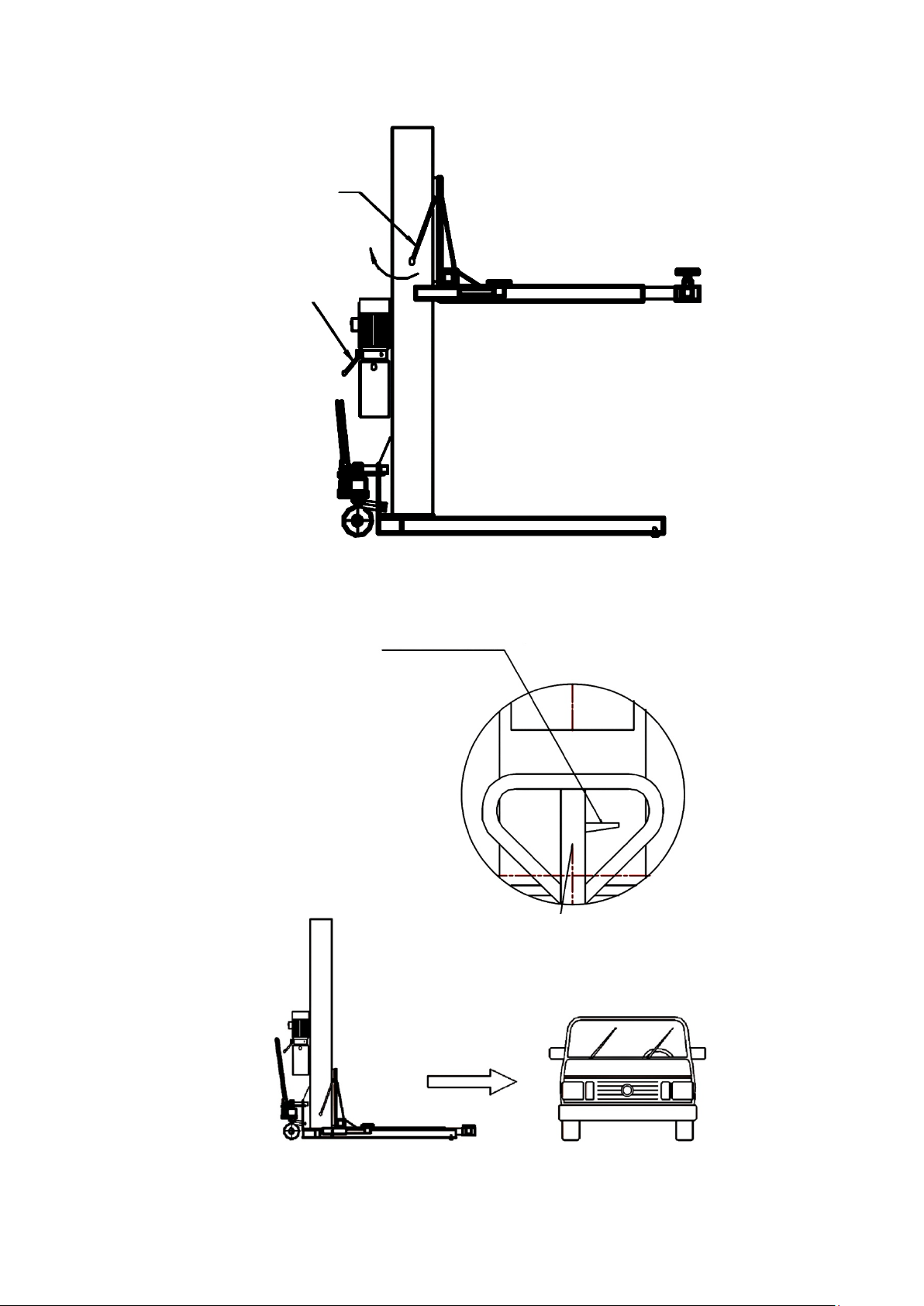
Unlock
Discharge valve
(lowering lever)
Handle
Handle
5.1 Operation
.
Put the mobile 1 Colum lift under the vehicle
Printing errors, mistakes and technical changes reserved.
V01.NK.618_EN
© by Twin Busch Germany GmbH 24
Page 25
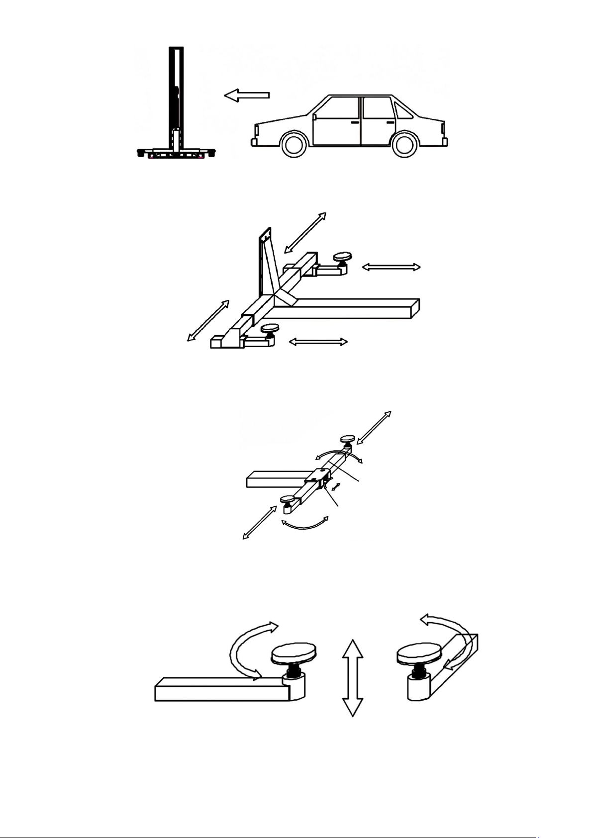
Safety device
Arm
Pull the safety bolts, you can now adjust the support arms,
or drive the vehicle on the lift.
.
You can adjust the support arms as follows:
Release the safety latches to lock the support arm.
Turn the Plates to set the high.
Printing errors, mistakes and technical changes reserved.
V01.NK.618_EN
© by Twin Busch Germany GmbH 25
Page 26

6. Maintenance and troubleshooting
6.1 Daily check
A daily check of the safety functions before putting the lift into operation is very important.
Discovering a device failure before use saves you time, greater damage or even injury.
- Check all hydraulic connections.
- Check all cables and switch connections.
- Check all bolts and screws, if loose, please tighten.
- The working environment should be cleaned regularly.
6.2 Monthly check
-Check the mobility of the flexible parts.
- The entire construction should be inspected for any signs of wear, if any damage has been discovered, it should be repaired or,
if necessary, replaced with original spare parts.
- If you detect a leak on the cylinder neck, this is probably due to wear of the seal ring on the piston.
He needs to be renewed.
6.3 Maintenance interval
- After 12 month should be renew the oil and the filter.
6.4 Troubleshooting
No power
- Check the power supply
- The electrical connection is wrong
The lift rises, but not to the maximum load of 2500 kg.
- Set the necessary pressure.
- If you are still experiencing lifting problems, remove the pressure relief valve and clean it.
If you hear unusual noises during the lifting process from the hydraulic system, it may be that air is being drawn in. Check the oil
level and clean or replace the filter.
6.5 General note
- Maintenance work may only be carried out by qualified personnel.
- Turn off the power before starting maintenance.
- Work on the circuit must only be carried out by a qualified electrician.
- Never use high-pressure cleaner or corrosive cleaning agents.
- Manipulating the safety devices is strictly prohibited.
- In case of disturbances, such as jerky movements or bending of load-bearing parts, leave the lift
shut down the power supply immediately and contact your supplier.
Printing errors, mistakes and technical changes reserved.
V01.NK.618_EN
© by Twin Busch Germany GmbH 26
Page 27
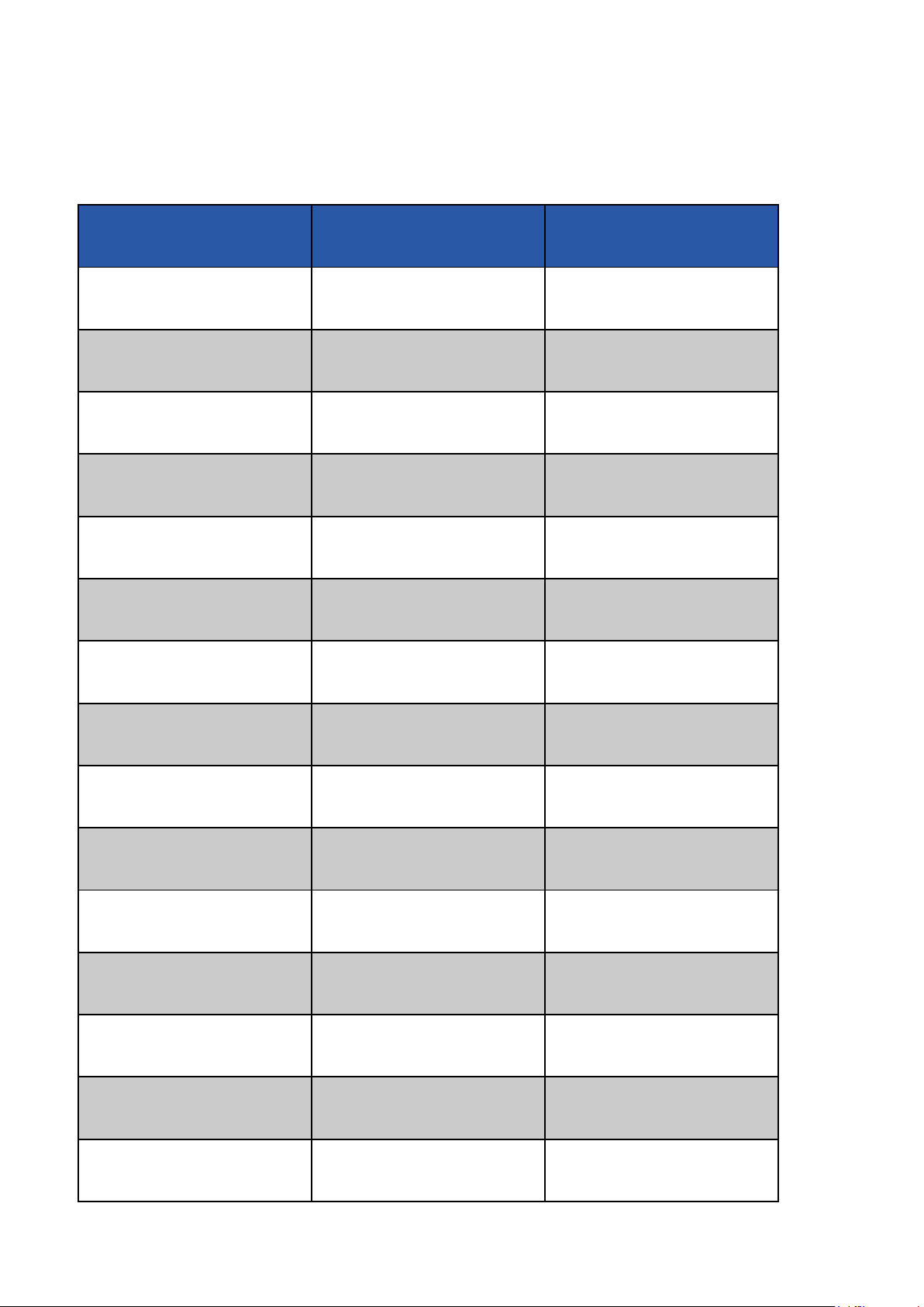
7. Annex
Tech. Data
TW 125 M Ultra
(Mobil)
TW 125 F
(fixed)
Capacity
2500 kg / 5511 Lb
2500 kg / 5511 Lb
Max. Wheelbase
2900 mm / 114 In
2900 mm / 114 In
Max. high
1800-2000 mm / 70-78 In
1800-2000 mm / 70-78 In
Vehicle width
≤1800 mm/ 70 In
≤1800 mm / 70 In
Lifting speed (ca.)
35 sec.
35 sec.
Motor power
2.2 kW
2.2 kW
Power supply
230 V
230 V
Frequency
50Hz/60 Hz
50Hz/60 Hz
Oil Pressure
115 bar / 1687 psi
115 bar / 1687 psi
weight (ca.)
720 kg / 1587 Lb
720 kg / 1587 Lb
Loudness
<60 dB
<60 dB
dimension (ca.)
2470x2030x2600 mm
2060x2030x2600 mm
Protect class
IP 64
IP 64
Working temperature
-5°C / 23°F till +40°C / 104°F
-5°C / 23°F till +40°C / 104°F
operating environment
inside and outside (limited)
inside and outside (limited)
7.1 Technical data
Printing errors, mistakes and technical changes reserved.
V01.NK.618_EN
© by Twin Busch Germany GmbH 27
Page 28
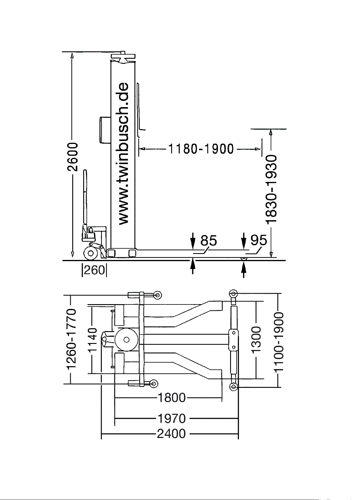
7.2 Dimension / TW 125 M Ultra
Printing errors, mistakes and technical changes reserved.
V01.NK.618_EN
© by Twin Busch Germany GmbH 28
Page 29
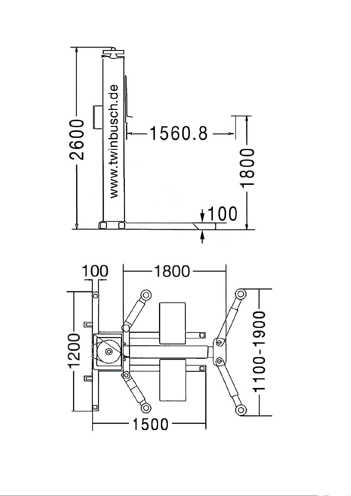
7.3 Dimension / TW 125 F
Printing errors, mistakes and technical changes reserved.
V01.NK.618_EN
© by Twin Busch Germany GmbH 29
Page 30
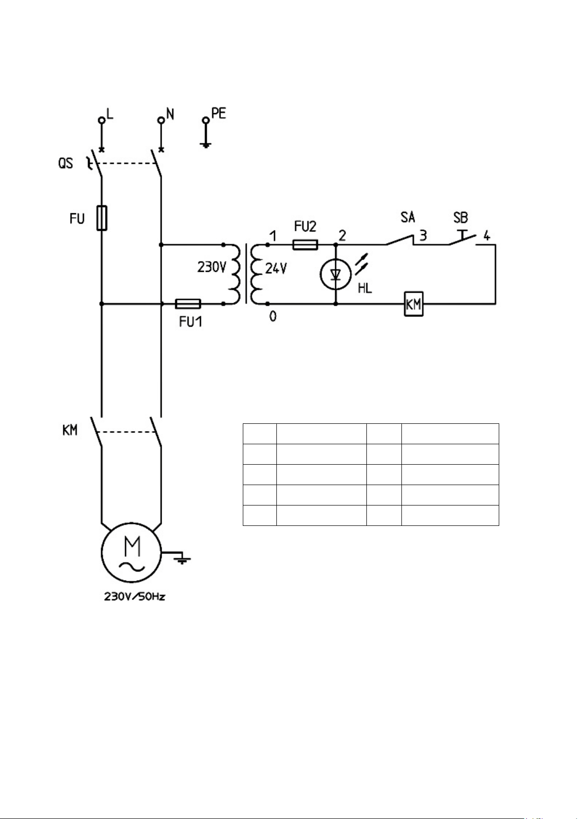
7.4 Wire diagram 230V
TC
Transformer
HL
lamp
FU
fuses
KM
Motor protection
QS
Main switch
SA
switch
SB
button
Wire diagram 230V
TW 125 M, TW 125 F
© Twin Busch GmbH
27.01.2016
Printing errors, mistakes and technical changes reserved.
V01.NK.618_EN
© by Twin Busch Germany GmbH 30
Page 31
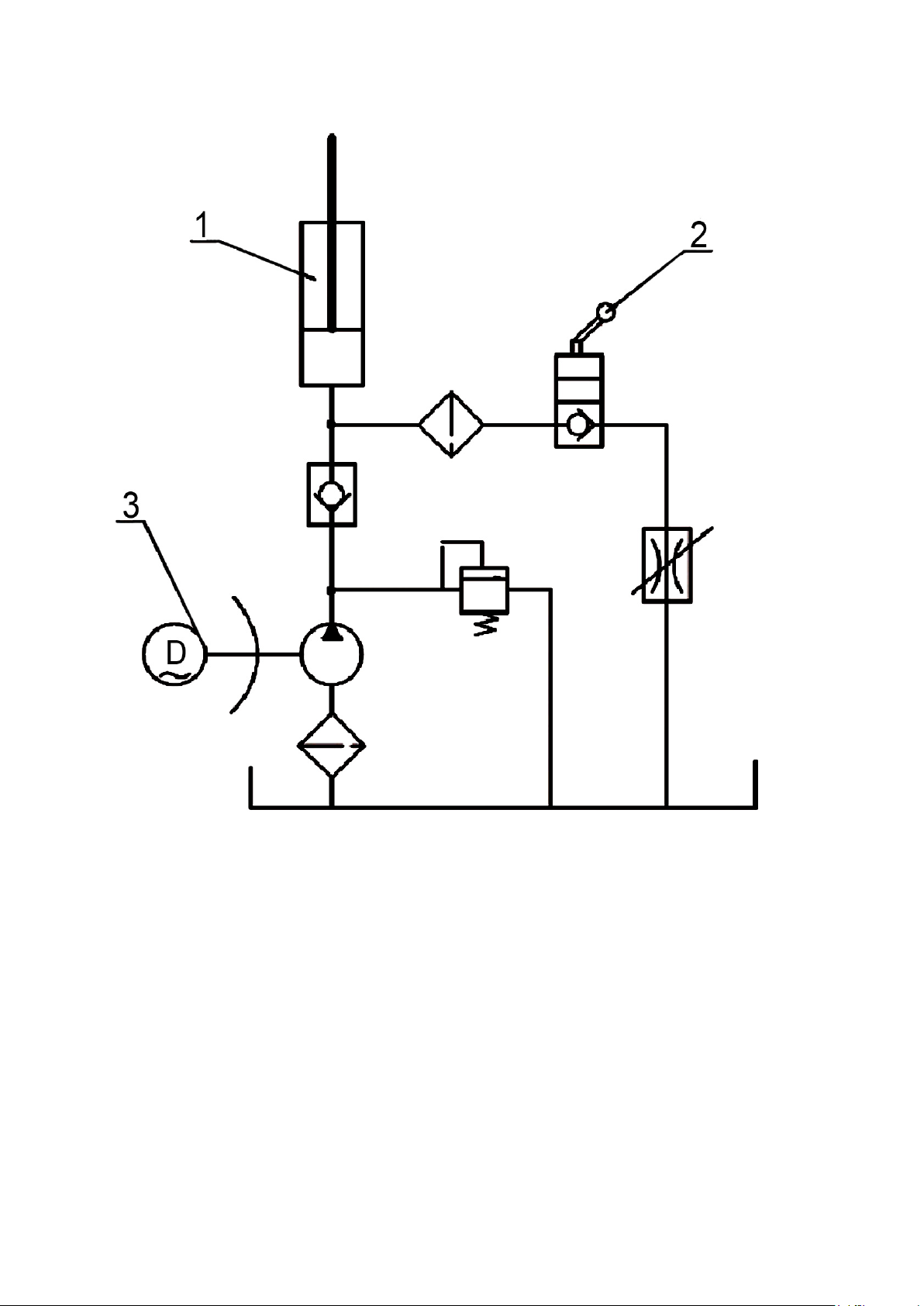
7.5 Hydraulic diagram
1. Cylinder
2. Valve
3. Pump
Printing errors, mistakes and technical changes reserved.
V01.NK.618_EN
© by Twin Busch Germany GmbH 31
Page 32
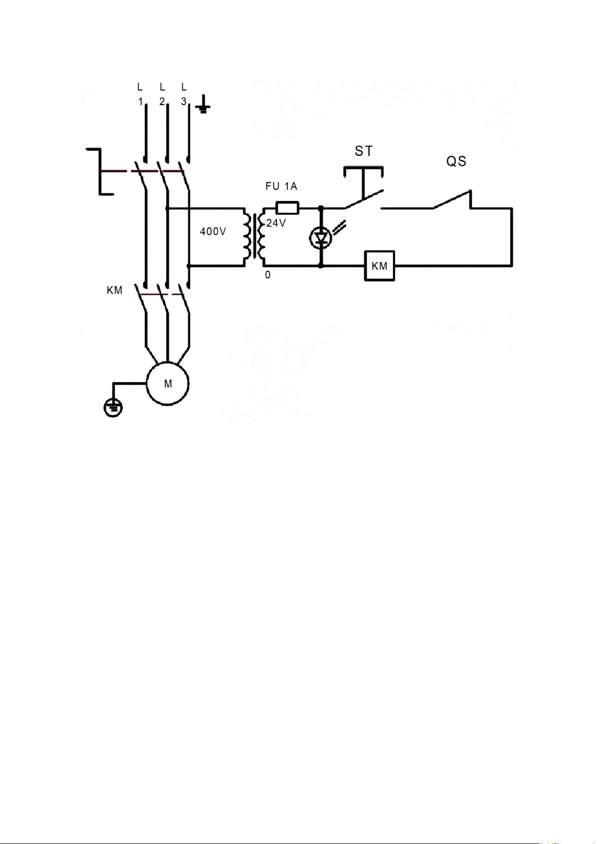
7.6 24V- diagram
Motor (3-Phasen)
24V-diagramm
Printing errors, mistakes and technical changes reserved.
V01.NK.618_EN
© by Twin Busch Germany GmbH 32
Page 33
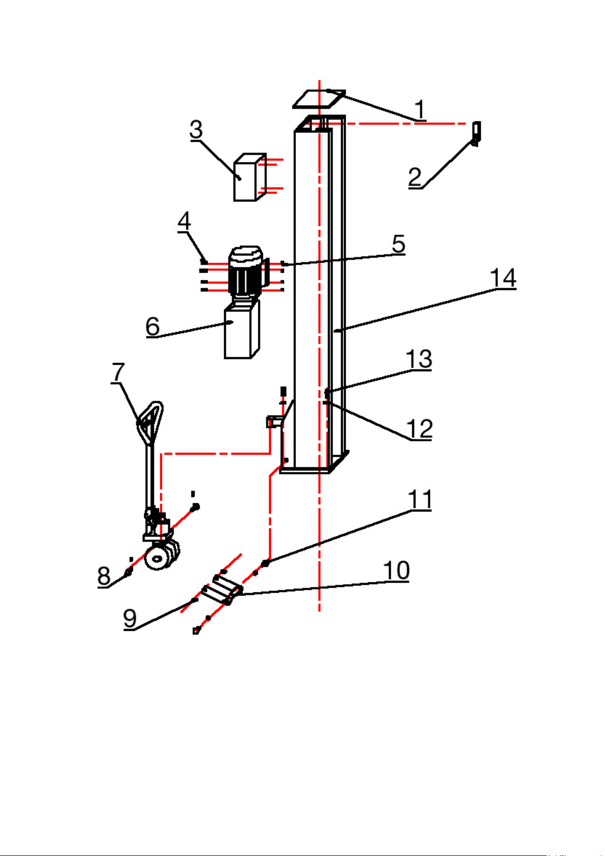
7.7 Spear parts
Printing errors, mistakes and technical changes reserved.
V01.NK.618_EN
© by Twin Busch Germany GmbH 33
Page 34
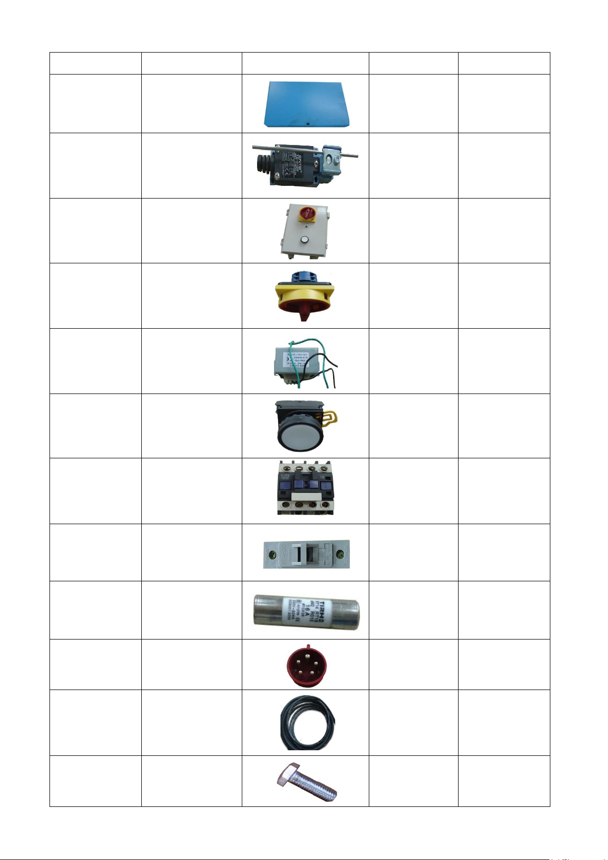
S/N.
name
picture
QTY.
Spez.
TW 125-1
Colum cover
1
TW 125-2
Limit switch
1
TW 125-3
Control box
1
TW 125-3,1 (1)
main switch 20A
1
TW 125-3,1 (2)
Transformer BK-30
1
TW 125-3,1 (3)
button
1
TW 125-3,1 (4)
Motor switch
CJX2-1201/24V
1
220/230 V
TW 125-3,1 (5)
Holder for fuses
3
TW 125-3,1 (6)
fuses 16A
3
TW 125-3,1 (7)
CEE-plug 16A
1
TW 125-3,1 (8)
cable
6
TW 125-4
screw M10*30
4
Printing errors, mistakes and technical changes reserved.
V01.NK.618_EN
© by Twin Busch Germany GmbH 34
Page 35
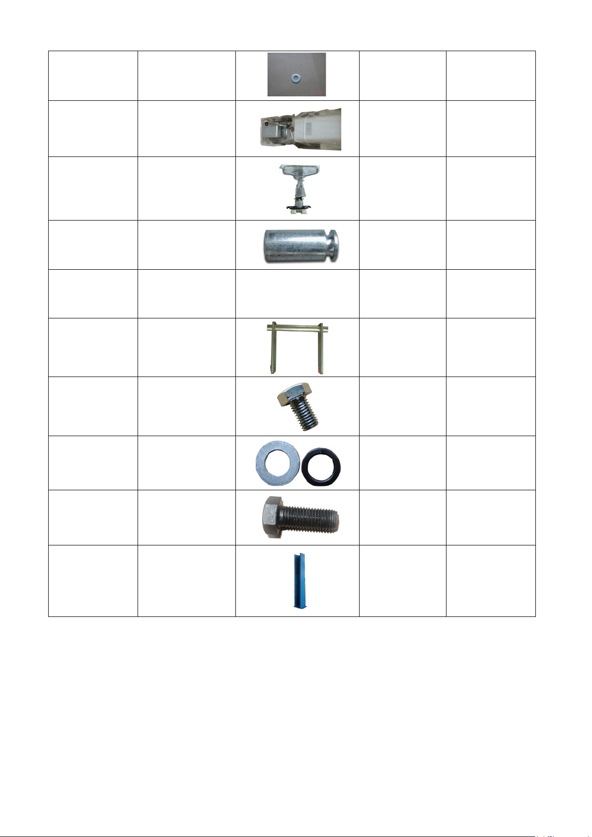
TW 125-5
nut M10
4
TW 125-6
Manual Pump
1
TW 125-7
carrier
1
mobil
TW 125-8
bolt 2
TW 125-9
bush
2
TW 125-10
axle 1
mobil
TW 125-11
screw M12*20
2
TW 125-12
washer
10
TW 125-13
screw
10
TW 125-14
Colum
1
Printing errors, mistakes and technical changes reserved.
V01.NK.618_EN
© by Twin Busch Germany GmbH 35
Page 36
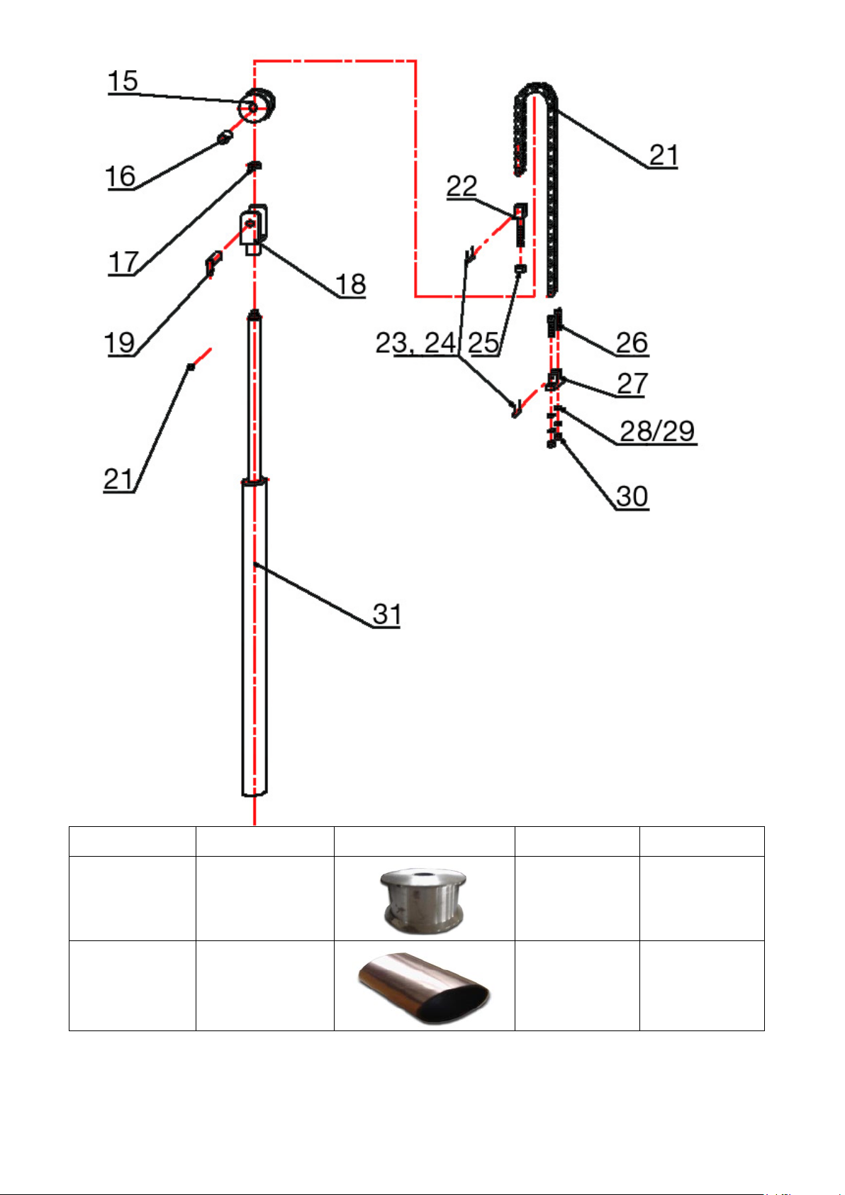
S/N.
name
picture
QTY.
Spez.
TW 125-15
roll 1
TW 125-16
Bearing 30*50
1
Printing errors, mistakes and technical changes reserved.
V01.NK.618_EN
© by Twin Busch Germany GmbH 36
Page 37
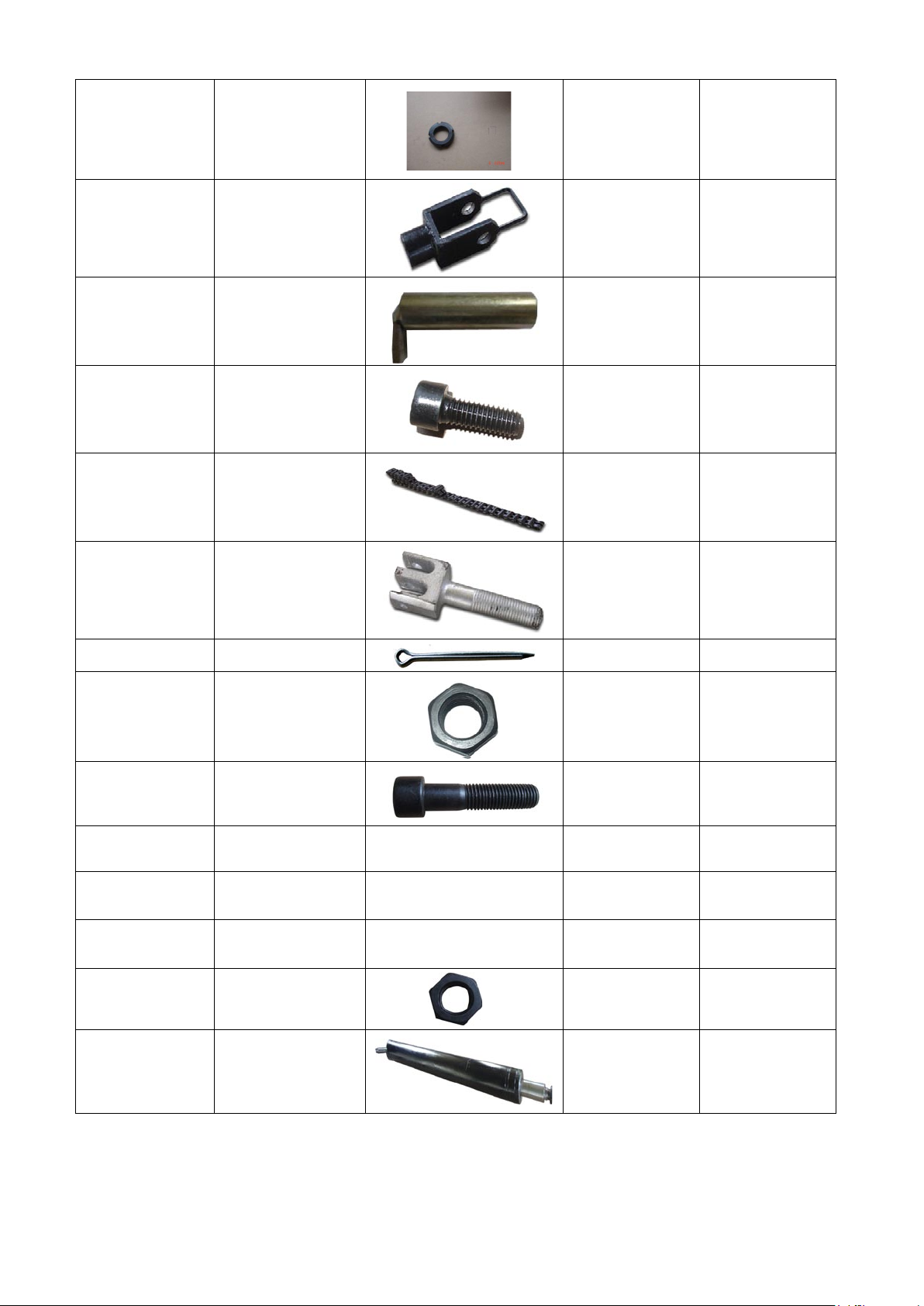
TW 125-17
nut M27*15
3
TW 125-18
holder
1
TW 125-19
Axle
1
TW 125-20
screw
M6*12
1
TW 125-21
chain Duplex
1
TW 125-22
Chain holder
1
TW 125-24
pin 2 2
TW 125-25
nut M20
1
TW 125-26
screw
M16*70
2
TW 125-27
Chain connector
1
TW 125-28
washer
2
TW 125-29
Spring washer 16
2
TW 125-30
Nut M16
2
TW 125-31
Hydraulic cylinder
1
Printing errors, mistakes and technical changes reserved.
V01.NK.618_EN
© by Twin Busch Germany GmbH 37
Page 38
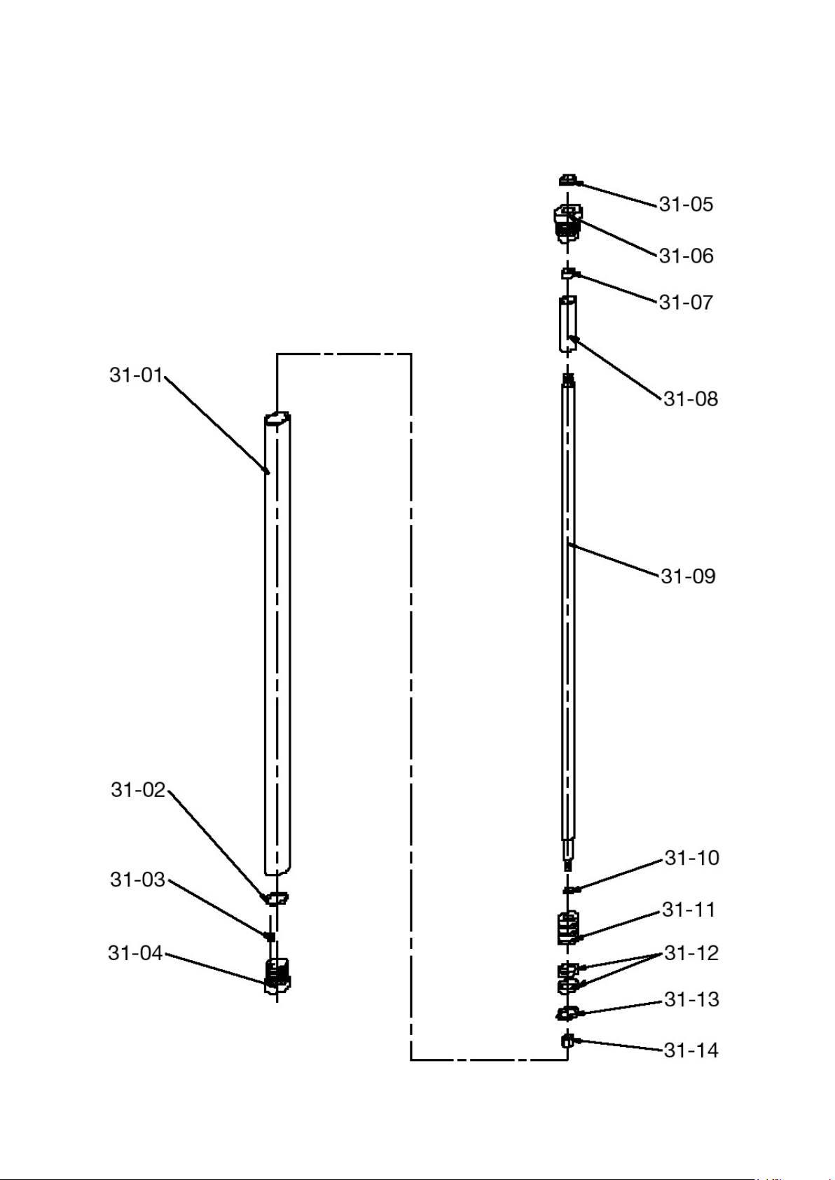
Printing errors, mistakes and technical changes reserved.
V01.NK.618_EN
© by Twin Busch Germany GmbH 38
Page 39
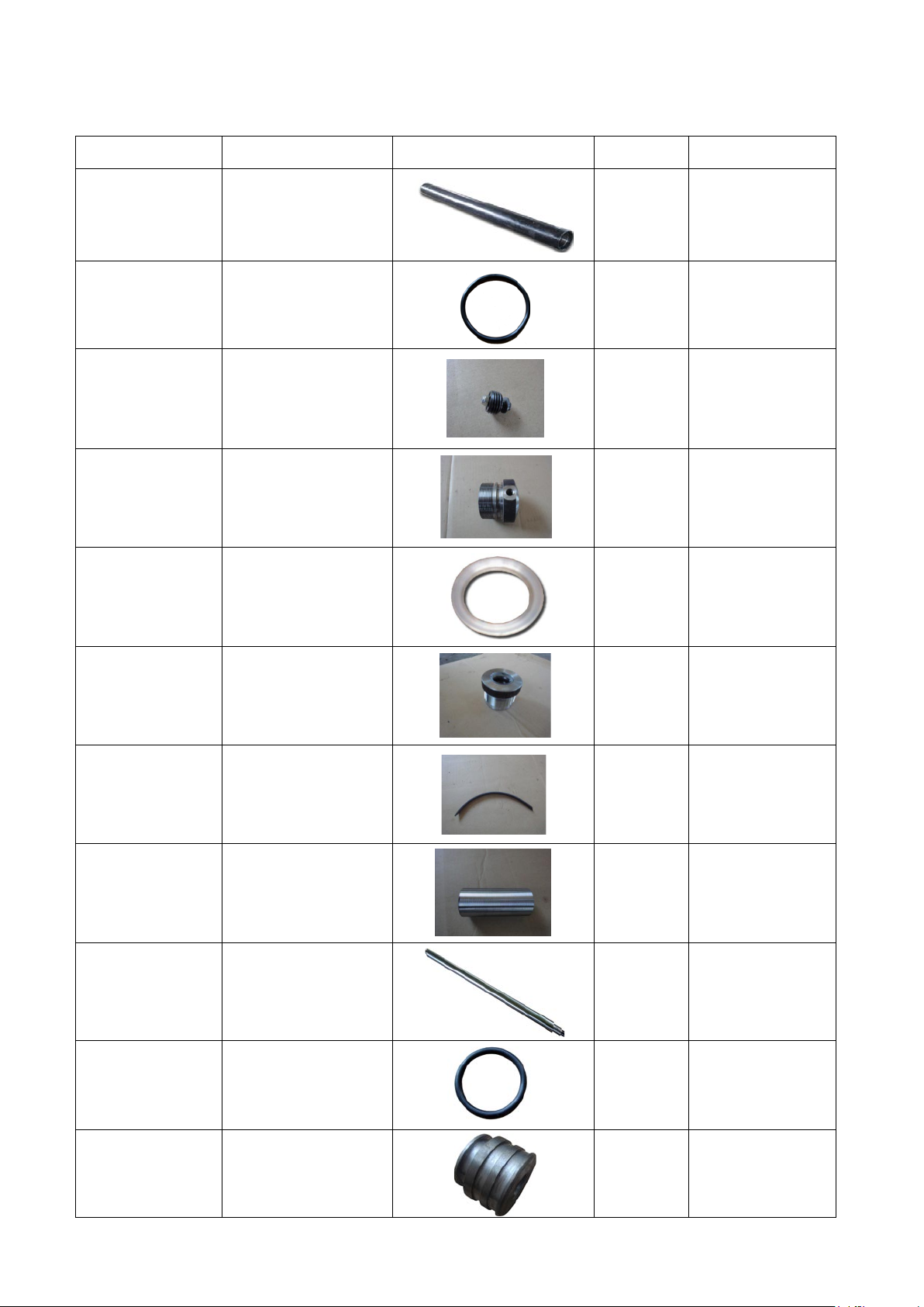
S/N.
name
picture
QTY.
Spez.
TW 125-31 (1)
Cylinder pipe
1
TW 125-31 (2)
O-ring 69*5.3
1
TW 125-31 (3)
valve
1
TW 125-31 (4)
Cylinder part
1
TW 125-31 (5)
sealing Ф45
1
TW 125-31 (6)
Cylinder head
2
TW 125-31 (7)
sealing
1
TW 125-31 (8)
Limiter
1
TW 125-31 (9)
Piston rood
1
TW 125-31 (10)
O-rings
1
TW 125-31 (11)
piston
1
Printing errors, mistakes and technical changes reserved.
V01.NK.618_EN
© by Twin Busch Germany GmbH 39
Page 40
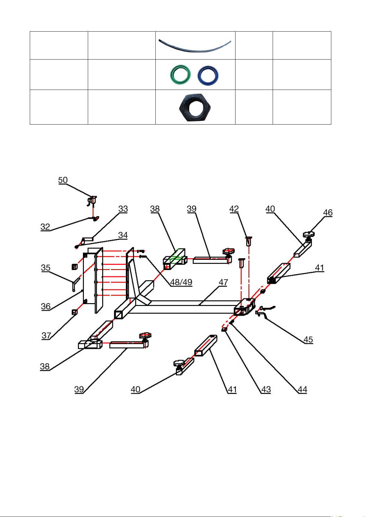
TW 125-31 (12)
sealing
2
TW 125-31 (13)
U-rings
1
currently use Green,
later Blue
TW 125-31 (14)
nut
1
Printing errors, mistakes and technical changes reserved.
V01.NK.618_EN
© by Twin Busch Germany GmbH 40
Page 41
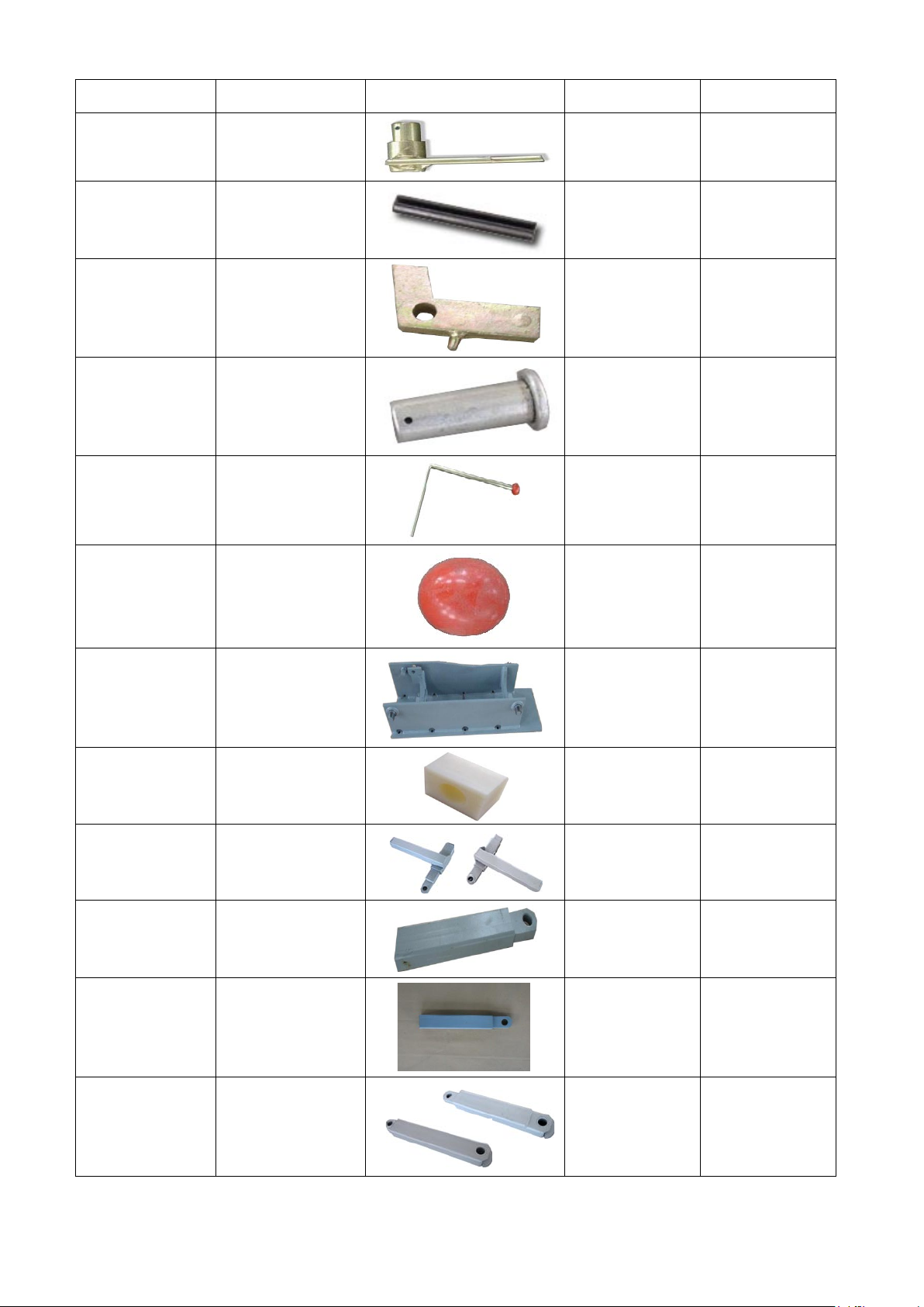
S/N.
name
picture
QTY.
Spez.
TW 125-32
lever 1
TW 125-32
(1)
pin Ф4*30
1
TW 125-33
lock 1
TW 125-34
bolt 1
TW 125-35
handle
1
TW 125-35 (1)
Ball for handle
1
TW 125-36
Lift slet
1
TW 125-37
PA-slider
1
TW 125-38
arm 2
TW 125-39
Arm
2
TW 125-39,1
arm 2
TW 125-40
arm 2
Printing errors, mistakes and technical changes reserved.
V01.NK.618_EN
© by Twin Busch Germany GmbH 41
Page 42
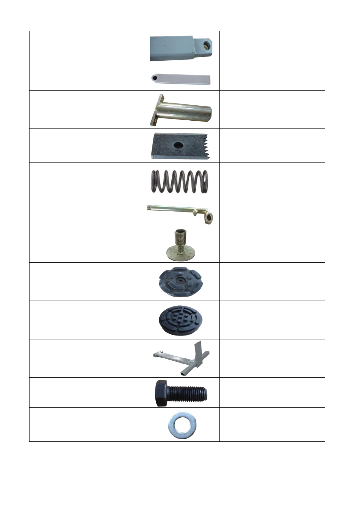
TW 125-41
arm 2
TW 125-41,1
arm 2
TW 125-42
Bolt for arm
1
TW 125-43
Tooth block
2
TW 125-44
spring
1
TW 125-45
Lock system
2
TW 125-46
Holder
4
TW 125-46 (1)
rubber
4
TW 125-46
(1,1)
rubber/Ultra flat
4
TW 125-47
Main arm
1
TW 125-48
screw M16*40
8
TW 125-49
washer
8
Printing errors, mistakes and technical changes reserved.
V01.NK.618_EN
© by Twin Busch Germany GmbH 42
Page 43
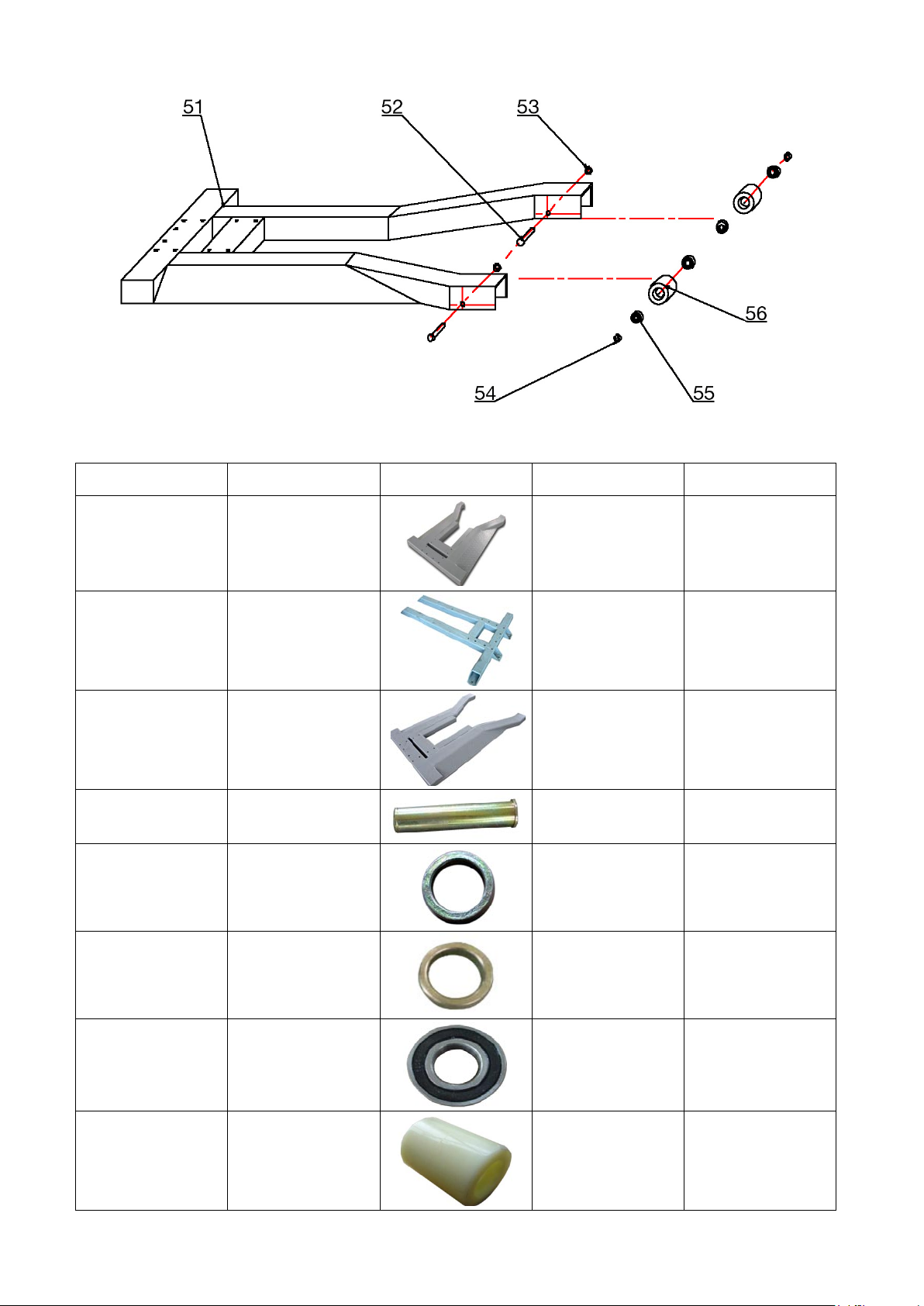
S/N.
name
picture
QTY.
Spez.
TW 125-51
Base frame
1
Mobil
TW 125-51,1
Base frame
1
Fixed mounted
TW 125-51,2
Base Frame/Ultra flat
1
Mobil
TW 125-52
axle 2
TW 125-53
ring 4
TW 125-54
spacer ring
4
TW 125-55
bearing
4
mobil
TW 125-56
Wheel 2
mobil
Printing errors, mistakes and technical changes reserved.
V01.NK.618_EN
© by Twin Busch Germany GmbH 43
Page 44
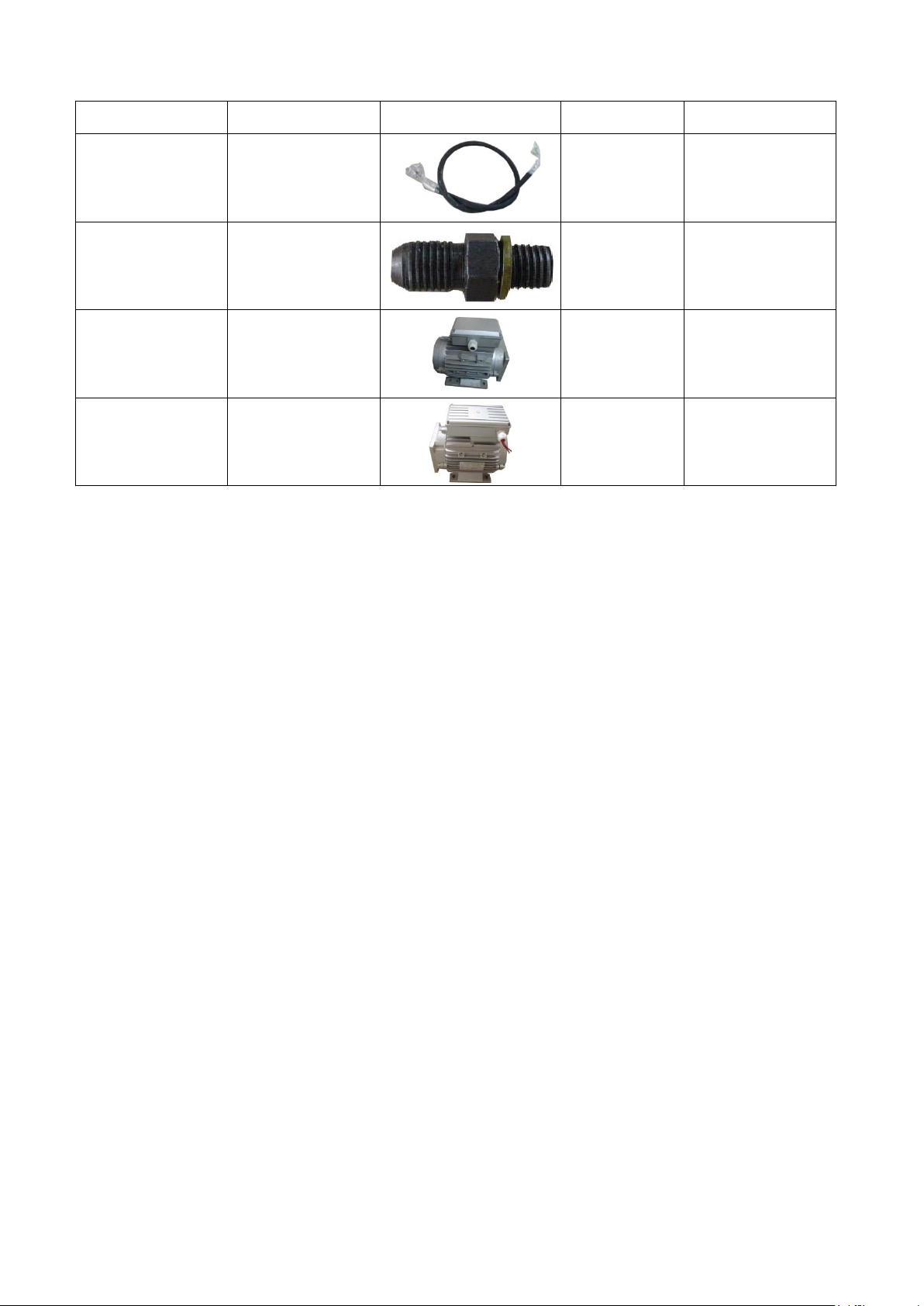
S/N.
Name
picture
QTY.
Spez.
TW 125-57
hoses
1
TW 125-58
connector
1
TW 125-59
Motor
1
300/400 V
TW 125-59,1
Motor
1
300/400 V
Printing errors, mistakes and technical changes reserved.
V01.NK.618_EN
© by Twin Busch Germany GmbH 44
Page 45

Space for my notes:
Printing errors, mistakes and technical changes reserved.
V01.NK.618_EN
© by Twin Busch Germany GmbH 45
Page 46

Space for my notes:
Printing errors, mistakes and technical changes reserved.
V01.NK.618_EN
© by Twin Busch Germany GmbH 46
Page 47

Space for my notes:
Printing errors, mistakes and technical changes reserved.
V01.NK.618_EN
© by Twin Busch Germany GmbH 47
Page 48
Printing errors, mistakes and technical changes reserved.
V01.NK.618_EN
© by Twin Busch Germany GmbH 48
Page 49
Printing errors, mistakes and technical changes reserved.
V01.NK.618_EN
© by Twin Busch Germany GmbH 49
Page 50
Printing errors, mistakes and technical changes reserved.
V01.NK.618_EN
© by Twin Busch Germany GmbH 50
Page 51
Printing errors, mistakes and technical changes reserved.
V01.NK.618_EN
© by Twin Busch Germany GmbH 51
Page 52
Printing errors, mistakes and technical changes reserved.
V01.NK.618_EN
© by Twin Busch Germany GmbH 52
Page 53
Printing errors, mistakes and technical changes reserved.
V01.NK.618_EN
© by Twin Busch Germany GmbH 53
Page 54
Printing errors, mistakes and technical changes reserved.
V01.NK.618_EN
© by Twin Busch Germany GmbH 54
Page 55
http://www.youtube.com/watch?v=UI82fUVgsSU
http://www.youtube.com/watch?v=3A9rlP27Ylw
Printing errors, mistakes and technical changes reserved.
V01.NK.618_EN
© by Twin Busch Germany GmbH 55
Page 56
Printing errors, mistakes and technical changes reserved.
V01.NK.618_EN
© by Twin Busch Germany GmbH 56
 Loading...