

Page 1
ELECTRONIC COMPONENTS
LP4 STXi
USER MANUAL
TW LP4 STXi (Location Production) stereo microphone mixer is a compact
portable four-channel unit designed for electronic news gathering (ENG)
quality sound mixing in a motion picture or television film.
Page 2

LEFT SIDE PANEL
Ÿ Balanced channel inputs – four electronically balanced circuits (transformer balanced is optional)
in phase with one another. XLR connectors should be wired as pin1 ground, pin2 +phase signal and
pin3 –phase signal.
Ÿ Microphone powering selector switches – The input sensitivity in position D is DYN 200 = 0.2 mV
and no power. Selected 48, 12, T, mic powering, 10 dB of attenuation is automatically introduced,
considering the sensitivity of condenser mics.
Ÿ Phase reverse switches – Intended to compensate for a phase error due to wiring or mic
placement.
Ÿ Phantom on / off switch – The current consumption of the phantom power supply is 13 mA.
Phantom power supply may be switched off (only if using dynamic, wireless of T powering mics) to
increase the lifelength of the internal batteries between two chargings.
Ÿ Attenuation switches – The gain of the mic preamplifiers may be decreased by –10 dB in position
D. In positions 48, 12 and T the attenuation is –13 dB.
Ÿ Mic / line level switches – Selects mic or line to add –60 dB attenuation before the mic
preamplifiers.
Ÿ Optional NP1 Battery Holder – The switched mixer supply is derived either from the internal AA
batteries or from NP1 battery depending on the position of the panel side switch.
Page 3

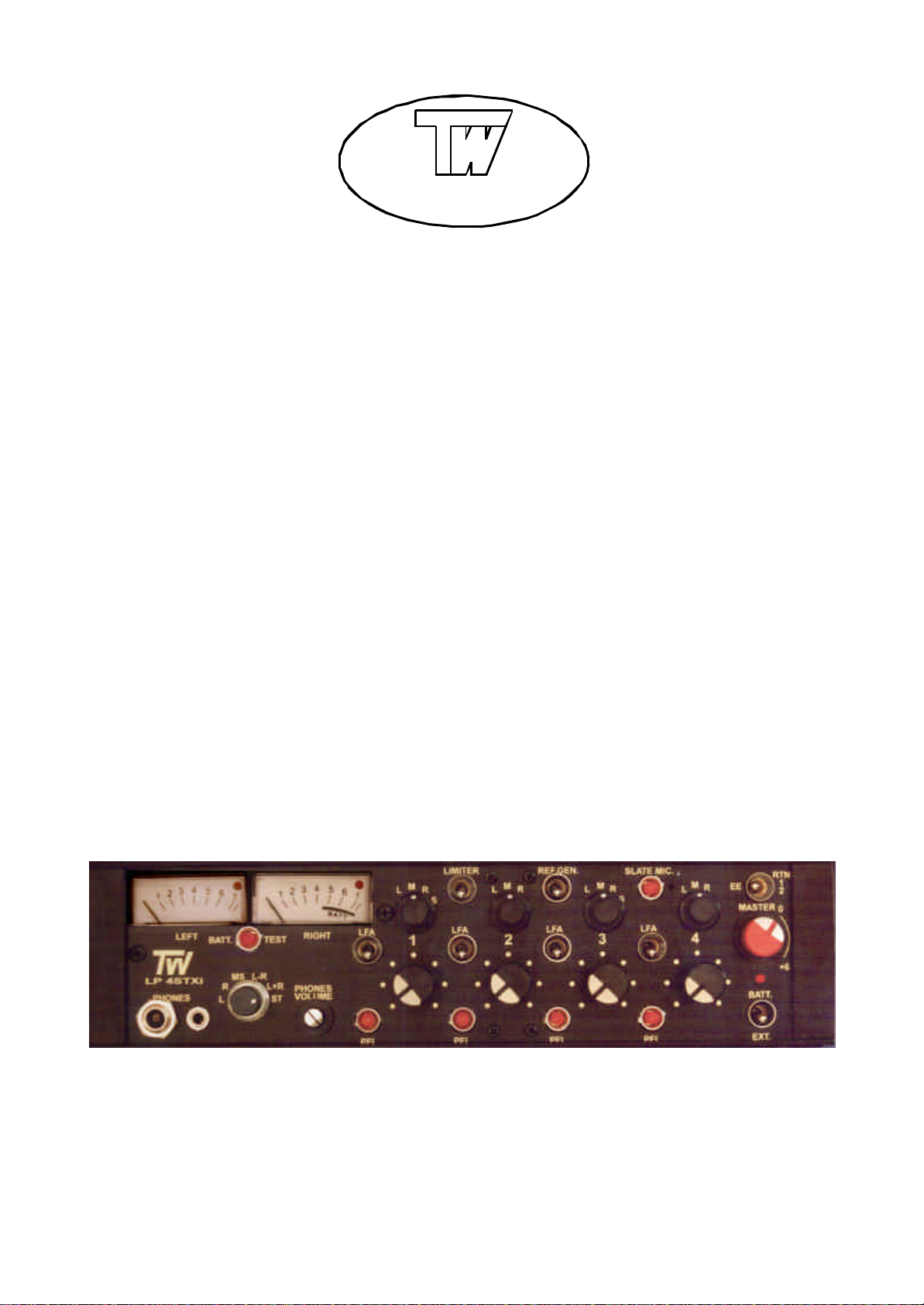
FRONT PANEL
Ÿ Modulometers – Continuous lighting, peak reading, BBC 1-7, dB or VU scaling, built-in red LEDs
indicate when the gain reduction is occurring with the limiters switched on.
Ÿ Battery check pushbutton
Ÿ 6.3 and 3.5 mm phone jacks
Ÿ Monitor selector switch – ST stereo. L+R sum signals, phase check, MS stereo equivalent Left.
L–R difference signals MS stereo equivalent Right. MS matrix, MS stereo equivalent. R right channel.
L left channel.
Ÿ Phones volume control – Output voltage into 50 Ω adjustable from 20 to 500 mV.
Ÿ Limiters on / off switches – The four individual limiters have fast attack time (less than 1 msec) and
a slow release time to smooth operation. Two red LEDs are built in the meters to indicate when the
limiters are selected and gain reduction is occurring. Threshold is internally set to +6 dBu at the
balanced output. To adjust the threshold for a value different from the supplied +6 dBu, see page
ADJUSTMENT POINTS.
Ÿ Reference generator switch – 1 kHz sine wave signal is fed to both left and right outputs, its level
can be controlled by the Master control.
Ÿ Slate microphone – It can be used either for identifying recorded segments or as an emergency
field microphone.
Ÿ Low -cut filter switches – Low frequency attenuation is 14 dB / octave at 100 Hz.
Ÿ Pan switches – Assign selected input signal to Left or Right output. In M position, equal amount of
signal is sent to Left and Right outputs. The S position of Pan switches 1 and 3 assigns Channels 1–2
and 3–4 as stereo pairs controlled by Channel 1 and 3 Faders respectively.
Ÿ Channel gain controls
Ÿ Pre -Fade Listen pushbuttons – Each channel can be checked by monitoring. Output audio signal
is not interrupted when the PFL pushbutton is activated.
Ÿ EE / RTN12 switch – A two-position switch selects the direct outputs from the mixer or the return 1
and 2 as a signal source for the monitoring.
Ÿ Master – The fader sets the gain of both Left and Right legs and has +6 dB of gain in hand with the
nominal 0 dB gain position marked.
Ÿ PWR LED – A red LED lights to indicate power is on. Flashes when voltage is 11.5 Vdc or less.
Ÿ Power switch – In position EXT the mixer will be powered by an external DC supply and in BATT by
the internal batteries. Batteries should be recharged with the switch in EXT position.
Page 4

RIGHT SIDE PANEL
Ÿ Balanced outputs – The main outputs are via transformer balanced XLR connectors and a Hirose
10pin multiway connector is also fitted to facilitate rapid connection of outputs and monitor returns.
The line level is set on 600 Ω at 0 dBu and +4 dBu for VU metered mixers. The Hirose 10pin
connector is wired as follows:
pin 1. +LEFT output pin 5. RIGHT return
pin 2. –LEFT output pin 6. N / C
pin 3. +RIGHT output pin 7. LEFT return
pin 4. –RIGHT output pin 8. N / C
pins 9., 10. GROUND
Ÿ Unbalanced output – A 5pin XLR connector carries an unbalanced stereo output signal – at a level
3 dB lower than balanced outputs – to feed a recorder, DAT, etc. and monitor returns. The XLR 5pin
connector is wired as follows:
pin 1. GROUND
pin 2. LEFT output pin 4. LEFT return
pin 3. RIGHT output pin 5. RIGHT return
Ÿ Line / mic level switch – The line level at XLR and Hirose connectors can be attenuated by 50 dB
to provide the microphone level.
Ÿ 3.5 mm stereo monitor input jack
Ÿ Return 1 or 2 selector switch – In position RTN1 the 3.5 jack and Hirose returns are chosen for
monitor, switched to RTN2 the returns of XLR7 will be fitted by the monitoring circuits.
Ÿ Power supply – The mixer may be powered by 12 pieces internal AA size rechargeable batteries or
an external DC supply 12-24 Vdc. Fully charged Panasonic P90AAS NiCd batteries will typically power
the mixer for 8 hours at continuous use. Full charging time is 14 hours. The external XLR 4pin
connector is wired as follows:
pin 1., 2. GROUND pin 3. Battery Charge pin 4. External 12-24 Vdc
Ÿ Optional NP1 Battery Holder – The switched mixer supply is derived either from the internal AA
batteries or from NP1 battery depending on the position of the panel side switch.
Page 5

ADJUSTMENT POINTS
Ÿ Gain and modulometer adjustment – Connect an AC voltmeter to the Left balanced line output.
Set channel 1 pan switch to L position, turn channel 1 fader fully clockwise, Master potentiometer in
0 dB position and switch LFA off. Connect an audio generator 1 kHz 0 dBm attenuator –80 dB to Mic 1
Input and adjust TRIMAL in the Left Limiter amplifier to obtain 0 dBu (+4 dBu on VU metered mixers) at
the Left balanced output. Then adjust TRIMM1 in the Left Modulometer amplifier board to obtain 0 dB
on the Left meter. Cut off the input signal and switch on the Reference Generator . Adjust TRIMRG to
obtain 0 dB on the Left modulometer. Repeat for Right output and Right modulometer.
Ÿ Limiter threshold adjustment – Connect an AC voltmeter to the Left balanced line output. Apply a
1 kHz signal until the AC voltmeter reading is at the level desired with limiter switched off. Switch on
the limiter and adjust TRIM
in Left limiter amplifier until the level drops 0.5 dB. Repeat for Right
LL1
output and Right limiter trimpot.
Page 6

XLR5
UNBAL.
OUT
XLR
L
ATT
OUT
10
HIROSE
HI LO
XLR
R
OUT
3.5
JACK
RTN
RTN
1
1
EE
DC
3 2
4 1
2
2
BATT
EXT
LINE L
LIMITER L
PAN L
METER
DRIVER
L R MASTER
SLATE
MIC
LINE R ATT
LIMITER R
PAN R
MONITOR
L
PHONES
P
MS
MATRIX
SELECTOR
L
F
P
R
PHONES
VOLUME
E
S
HON
6.3 3.5
10 Vdc
VOLTAGE
STABILIZER
PACK
BATTERY
TW LP4 STXi
Schematic Diagram
L R
T
PAN
LFAPPS
MIC
ATT PRE
2
SWITCH
PFL
AMP
3
1
T
PAN
LFAPPS
MIC
ATT PRE
2
SWITCH
PFL
AMP
3
1
T
PAN
LFAPPS
MIC
ATT PRE
2
SWITCH
PFL
AMP
3
1
T
PAN
MIC
2
LFA
PRE
ATTPPS
SWITCH
PFL
AMP
3
1
Page 7

SPECIFICATIONS
Ÿ Inputs
Microphone: four transformerless XLR female
Sensitivity: –75 dBu
Maximum input level: –20 dBu
Microphone power: 48 V, 12 V, T (DIN AB)
Line attenuation: adds 60 dB attenuation before the mic preamp.
Signal to Noise ratio: > 65 dB, Equivalent Input Noise: –125 dBu
Frequency response: 20 Hz - 20 kHz ±2 dB
Harmonic distortion: less than 0.2 %
Low-cut filter: 100 Hz / 14 dB octave
Crosstalk isolation, channel to channel: < –65 dB
Ÿ Outputs
Line: transformer balanc ed XLR
Line level on 600 Ω 0 dB on the modulometer: 0 dBu
4 on the 1–7 scaling: 0 dBu
0 Vu on the VU scaling: +4 dBu
Unbalanced line and monitor returns
Maximum output level: +18 dBu
Ÿ Internal power: 12 AA size rechargeable batteries
Ÿ External power: 11–25 Vdc
Ÿ Power consumption: 90 mA
Ÿ Dimensions: 255 × 165 × 65 mm (10 × 6.5 × 2.6 in)
Ÿ Weight: 2 kg (4.2 lbs)
ELECTRONIC COMPONENTS
Kaptárko u. 11. tel.: +36 1 2466549
Budapest H-1118 fax: +36 1 2480194
HUNGARY e-mail: twelco@chello.hu
www.twelco.hu
 Loading...