

Tweeny MAYFAIR, CHELSEA, CHELSEA-PLUS, VICTORIA, WESTMINSTER Operating And Installation Manual
...
Twe
e
ny
Domestic Food Waste Disposal Units
Thank you for choosing the most environmentally
friendly way of disposing of your food waste.
Remember at the end of the machines
life we can collect it and recycle it.
MAYFAIR CHELSEA CHELSEA-PLUS VICTORIA
KENSINGTON WESTMINSTER 125
Operating and Installation Manual

When contacting our service department or service agents concerning your waste disposal unit you will be
asked to quote the serial number to identify your machine model.
Guarantee
This Guarantee is subject to the following conditions:
1. The Guarantee is valid only if the serial number attached to the unit is not defaced in any way.
2. The Guarantee will be void if the unit is dismantled by any person other than an authorised
Dealer or Service Agent.
3. The Guarantee will be void if the unit is used for any purpose other than domestic household
food waste in accordance with the operating instructions.
4. This Guarantee does not cover wear and tear.
5. This Guarantee covers the original registered user only.
6. If your machine is not registered within 30 days of purchase Statutory 12 months warranty will apply.
7. Warranty is for domestic use only.
SERIAL NUMBER

Name:
Address:
Telephone:
Purchased from:
Date of purchase:
SERIAL NUMBER
Twe
e
ny
Please complete the registration card within 30 days, return complete with a copy of
proof of purchase to receive your extended manufacturers warranty.
To fi nd out more about our range of accessories including air switches, gold and brass
sink outlets please tick:
Guarantee Registration card

FREEPOST SEA 11333
Hastings
TN35 4BR
Please fold here and seal

Contents
3. User instructions - all models (excluding Westminster - see page 14)
6. General Installation notes - all models (excluding Westminster - see page 16)
7. Installing the suspension unit - all models (excluding Westminster - see page 16)
8. Fitting the waste disposer - all models (excluding Westminster - see page 16)
10. Fitting the actuator - Mayfair model only
12. Electrical installation - all models (excluding Westminster - see page 18)
13. Service Arrangement
14. Westminster - User instructions
16. Westminster - Installation instructions
Page

Model identifi cation
Mayfair
Chelsea
Westminster
Kensington Victoria 125-X
2

User instructions
You have just purchased a Tweeny food waste disposer and we want it to give you
satisfaction and prove a useful asset to your home.
Tweeny will swiftly dispose of all wastes such as tea-leaves, vegetable peelings and plate
scraps. It will not dispose of string, glass, rubber, leather, metallic objects or stringy items
such as runner bean strings, leek, celery, artichoke leaves, and asparagus haulms.
The unit accepts all normal domestic foodwaste except larger and uncooked bones
(chicken carcasses and chop bones are fully acceptable). Bulkier items such as melon rinds,
cabbage stalks, orange halves etc. should be cut into smaller pieces for disposal.
Prevent dishcloths, saucepan scourers or sink squeegees from slipping down the sink
outlet hole. Should this happen, stop the machine immediately, switch off the power
supply, and remove the article before it becomes wedged, freeing the impeller if necessary.
Waste such as bones, fruit stones and lobster shells are best disposed of when fed into
the machine with general kitchen waste as this holds them against the cutting element.
In the event of the unit becoming jammed for any reason, the overload protection will
cut off the power to prevent electrical or mechanical damage. If this happens switch off
the power supply and rectify the fault. Press the reset button on the unit, switch on the
power supply and restart the disposer. Should the unit fail to start please contact Tweeny
on 01424 751888.
Always see that an adequate supply of water is fl owing through the unit. If the disposer is
left running for a short while after the waste has disappeared it will ensure the automatic
cleaning of the unit and a trouble free start next time it is used.
Safety
This is a classed as an attended machine.
1. Never leave running unattended.
2. Disconnect the electrical supply before attempting any cleaning, maintenance or
repair.
3. Do not put any part of your body into the inlet to the machine.
4. Do not operate without a splashguard or plug (Westminster) in place.
5. The appliances should only be operated by a competent person.
6. Do not put metal or electrically conductive objects into the machine with out fi rst
disconnecting the power supply.
7. This is a domestic appliance, if you are using it in a commercial environment
additional regulations will apply, please consult us fi rst.
8. Remember this is a food waste disposer. Non food waste should be disposed of in
alternative environmentally friendly way.
3
User instructions
4
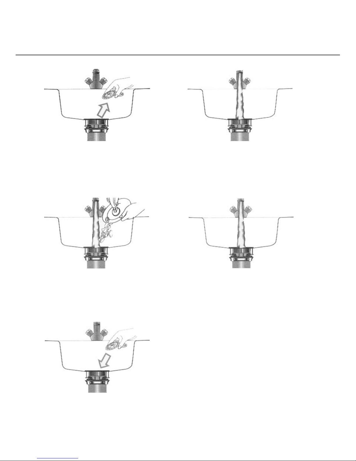
Remove the strainer.
Run cold water freely and switch on
the unit.
Feed in food waste through the tongued
splashguard using spatula supplied.
Switch off the unit and turn off water
shortly after grinding has ceased.
Replace the strainer.
12
3
4
5
ON
OFF

Controls
The MAYFAIR is controlled via the actuator which,
being non-electric, can be situated close to the taps or
wherever is most convenient, it is not to be used, though,
as a footswitch. The green light indicates that the unit is
operating. A red light indicates that the motor has been
overloaded and has cut out.
The CHELSEA, VICTORIA, KENSINGTON, & 125
models are controlled by a double-pole fused spur switch
(not supplied) on the wall, or optional air switch.
The CHELSEA PLUS is controlled by an air switch.
Reversing
Both the MAYFAIR and the CHELSEA are
automatically self-reversing: should a minor jam occur the
machine will instantly operate in the opposite direction
to help reduce jamming. This feature also ensures equal
wear on both sides of the cutter ring.
If a foreign object accidentally falls into the unit:
1. Switch off the machine immediately.
2. Switch off the machine at the mains.
3. Push the release key through the splashguard
and engage it on the impellor fi ns. Turn the
handle in either direction until the impellor
rotates freely, and remove the release key.
Remove any foreign objects.
4. Press the Reset button (Overload Protector).
5. Switch on the power and restart the Tweeny.
Should the disposer still fail to operate, call
01424 751888 for assistance.
Seal failure for Mayfair and Chelsea
Warning of seal failure is given by water seepage through
the bleedhole opposite the outlet elbow. In this event
call Tweeny 01424 751888.
In the event of a power cut
Switch off the disposer at the mains.
5
Mounting
The unique hinged mounting of the disposer has been designed to facilitate installation.
It also allows for the easy removal of the unit for servicing.
Fitting to sink
In order to fi t the sink mounting, an outlet hole of 89mm (3.5 ins) diameter centred within a 114mm
(4.5 ins) diameter recess is required.
Fittings required
38mm trap and discharge pipe. A ‘P’ or ‘S’ trap must be used, as bottle or grease traps are not suitable.
The bore of the trap and discharge pipe must be readily accessible and be provided with adequate means
of cleaning. The fall on the discharge pipe should not be less than 7.5 degrees to the horizontal.
Important points
1. This unit must be installed in compliance with the appropriate building
regulations and codes of practice.
2. When installing the unit care must be taken that the overload reset button and
reversing switch (when fi tted) are to the front and readily accessible.
3. The outlet elbow and trap must be in alignment to avoid strain.
4. In order to mount the disposer on, or remove it from, the suspension plate the base has to be swung
forward at least 180mm from the vertical. This must be taken into consideration when arranging
the radial position of the suspension plate, i.e. the hinge must be positioned at the front.
5. Minimum space required between underside of sink and top of plinth:
Mayfair and Chelsea: 475mm
Victoria and Kensington: 415mm
Westminster: 480mm
125: 460mm
6. The unit must drain completely.
General Installation Notes
all models except Westminster
6
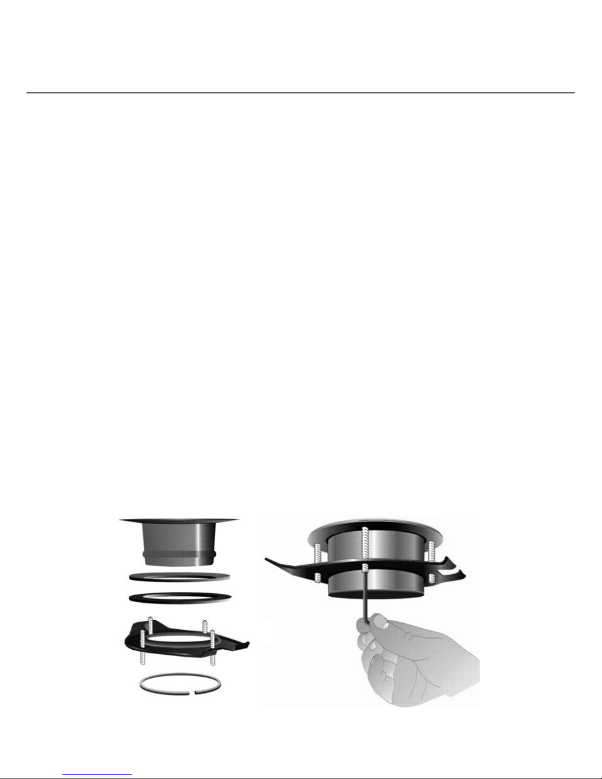
1. Ensure bottom of sink is smooth, clean and dry.
2. Remove the sink outlet assembly from the pack.
3. Using the allen key provided, unscrew the four screws until they are just below the top face
of the suspension plate.
4. The circlip can now be detached to allow for the removal of the suspension plate, pressure
plate, and rubber washer. The sink outlet is now free of all other items.
5. To the hole recess, between the sink outlet and the sink bowl, apply a liberal amount of
plumbers putty or silicone sealer. (Note: The rubber washer is not fi tted at this stage - it is
supplied for use on the underside of the sink bowl.)
6. Press the sink outlet down fi rmly on to this putty bed, squeezing out as much putty as possible.
7. On the underside of the sink, place in position the rubber washer, pressure plate and
suspension plate. Push these items up to the underside of the sink until the circlip can be
inserted over the swage of the sink outlet.
8. Ensure the suspension plate is level to the circlip and EVENLY tighten the four allen screws until the
suspension plate is held fi rmly in place, failure to level or uneven tightening may result in failure of the
circlip to hold.
9. Additional allen screws are supplied to accomodate thicker sinks.
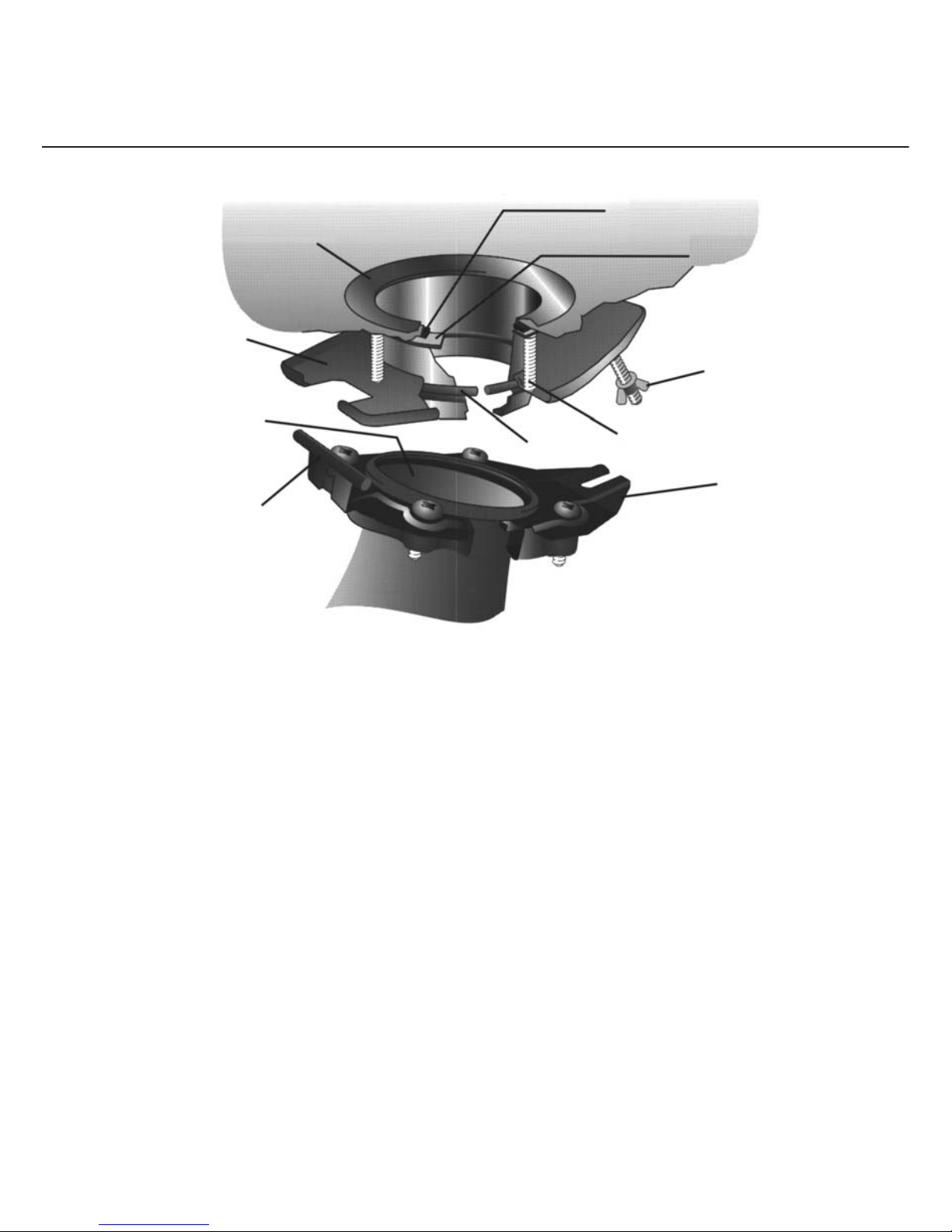
Installing the suspension unit
all models except Westminster
Carrier plate
Wing nut
Allen screws
Circlip
Hinge pin
Seal
Suspension plate
Sink outlet
Rubber washer
7

Fitting the waste disposer
all models except Westminster
Before mounting the disposer ensure that the hinge faces the front. The unit is supplied with a right hand
outlet, though machines can be supplied with a left hand outlet. A right hand outlet machine can be made
into a left hand outlet machine simply by unscrewing and re-aligning the carrier plate. In this case please
telephone the manufacturers for a suitable label. The discharge pipe must not be plumbed in front of the
disposer; this will enable the unit to be removed easily if servicing is required. Care must be taken to
ensure that the trap level is below the grinding chamber as it is essential that the chamber
drains down completely.
1. First fi t the outlet elbow to unit by placing gland nut, ring and rubber seal over outlet stub.
Ensure sloping side of rubber seal faces away from unit. Offer up outlet elbow and tighten.
2. Remove splashguard or seal from the unit.
3. Hang unit by hinge pin of the carrier plate on the suspension plate.
8

4. Swing the unit up into position and tighten the wing nut.
5. Slightly rotate the disposer as necessary on the circlip until the elbow is in correct alignment
with the drainage fi ttings.
6. Mark position of the suspension plate relative to the sink and remove the disposer.
7. Tighten up the four allen screws in the suspension plate.
8. Replace the splash-guard in the top of the disposer and lubricate the edges with soap or grease.
9. Re-hang unit on the suspension plate, swing it up, align carefully, and tighten the wing nut.
10. The outlet elbow may now be connected to the drainage system. It is essential to have no
sharp bends, vanes or obstructions in the waste pipe run from the disposer to the soil gully.
38mm bore pipe must be used throughout and there must be no change in section of the
bore due to free bending. The discharge end of the waste pipe must discharge below the grid
of the soil gully to prevent a build up of waste. N.B. The spigot on the outlet bend may be
opened to accommodate the discharge from a dishwasher or sink overfl ow.
An ‘S’ or ‘P’ type trap must be used. A bottle trap must not be used.
11. Ensure that there are no foreign objects in the grind chamber, fi ll the sink with water, remove
plug. Check for leaks. Always ensure there is an adequate supply of water fl owing through
the unit when switched on.
No Ye s
9

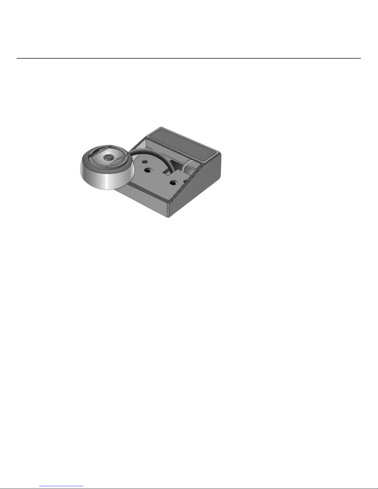
The self reversing actuator has also been designed for ease of installation. By squeezing and lifting the base
of the wall of the push-button below the pimpled surface, the push-button will come out, exposing the
bellows and the two fi xing holes. (See fi g.1)
For fi tting onto a facsia board or worktop
Cut a square hole (37mm x 37mm), so that the top of the square lines up with the inside of the top of the
actuator housing. Mark out and part drill the two holes on either side for the wood screws. Feed the end
of the sheath with the two identical lengths of pneumatic tube and fi bre-optic light guide through the back
of the hole (See fi g.2). Now see ‘Connecting the actuator’.
For fi tting in a wall
Chase out a channel in the wall to accomodate the sheath. It is advisable at this point to lay in 19mm
diameter electrical ducting in case at any time after installation, the fi xture needs attention. Remove one
of the knock-out panels from the metal box for the sheath to pass through, and bury this in the position
required, so that the edges are just below the surface of the wall. Fix it in the wall using rawplugs and the
two wood screws provided. Feed the sheath through so that the end with the two identical lengths of
pneumatic tube and fi bre-optic light guide protrude out of the box. Now see ‘Connecting the actuator’.
For fi tting on a wall
The spacer box ( Manufactured by Crabtree, list no 9043) matches the base of the actuator housing.
This is available through most elecricians, as also a suitable PVC or vinyl ducting to house the sheath.
Position these on the wall and feed the sheath through so that the end with the two identical lengths of
pneumatic tube and fi bre-optic light guide protrude out of the spacer box (See fi g. 2).
Now see ‘Connecting the actuator’.
Fitting the actuator
Mayfair model only
10
fi g.1
fi g.2
Connecting the actuator
The fi bre-optic light guide terminates in a brass ferrule at each end. This is fi rst plugged into the
socket on the back of the actuator housing which has the window on the facsia plate.
Light lubrication of the ferrule will assist its insertion if necessary. The pneumatic tube is passed through
the back of the actuator housing and plugged into the bellows (See fi g.3).
Screw down the actuator housing into its fi nal position. Press the bellows onto the two holes provided and
then reassemble the push-button. Check that neither the fi bre-optic light guide nor the pneumatic tube
have become kinked during this operation. The other end of the fi bre-optic light guide should now
be pressed fi rmly home into the aperture adjacent to the cable grommet at the base of the machine.
The pneumatic tube should be plugged fi rmly into the hexagonal nut between the grommet and the
reset button. Now see that any excess of sheath is tidily tucked inside the sink cupboard, checking that
nowhere is allowed to kink. It is essential that the pneumatic tube is fi tted fi rst to the actuator. Please
ensure fi bre optic is also plugged in.
11
fi g.3

12
Electrical installation
The fuse to be fi tted must be of a 10A rating.
This appliance must be installed in accordance with IEE regulations.
The unit must be connected to the supply by means of a non-detachable fl exible cord or by wires in a
fl exible conduit and means for disconnection must be incorporated in the fi xed wiring having a contact
separation of at least 3mm in all poles. When installing the unit, care must be taken that the overload reset
button remains readily accessible.
Warning: The unit must be earthed.
The wires in this mains lead are coloured in accordance with the following code:
Green and yellow: Earth
Blue: Neutral
Brown: Live
As the colours of the wires in the mains lead of the unit may not correspond with the coloured markings
identifying the terminals in the double-pole fused spur switch proceed as follows:
-The wire which is coloured green-and-yellow must be connected to the terminal in the switch which is
marked with the letter ‘E’ or by the earth symbol or coloured green or green-and-yellow.
-The wire which is coloured blue must be connected to the terminal which is marked with the letter
‘N’ or coloured black.
-The wire which is coloured brown must be connected to the terminal which is marked with the letter
‘L’ or coloured red.
If the supply cord of this appliance is damaged it must only be replaced by the manufacturer or one of the
manufacturer’s Authorised Service Agents. Before starting the unit for the fi rst time ensure that there are
no foreign objects in the grinding chamber and that there is an adequate supply of water fl owing through
the unit when it is switched on.

13
Service Arrangement
1. Please call 01424 751888 for your nearest Service Agent.
2. You will need to quote the serial number.
If the service is needed because of:
a. Misuse, poor installation or accident, i.e. a jammed condition you are unable to free yourself,
then the agent will clear it and charge you accordingly based on the agent’s time and distance.
b. A failure under Guarantee, then the agent will rectify the fault or replace the defective
part(s) free of charge to you. This is why it is important to return the guarantee registration
card within 30 days of purchase.
c. A failure out of Guarantee, then the agent will quote you either to rectify the fault, or offer to
replace the damaged part(s). In this case you will have to pay for the visit, any parts required
and work done.

BATCH FEED MODE
1. Remove the Magnitop plug and load the unit - DO NOT CRAM THE WASTE INTO THE UNIT.
2. Replace the plug in the “DRAIN” position.
3. Turn on the cold tap - a good fl ow is required.
4. Turn the Magnitop plug to the “GRIND” position.
5. When the grinding has fi nished, allow the unit to run for about 10 seconds.
6. Turn the Magnitop plug to the “DRAIN” position and turn off the water.
CONTINOUS FEED MODE
1. With the Magnitube in the “DRAIN” position, turn on the cold tap.
2. Turn the Magnitube to the “GRIND” position and feed waste.
3. When the grinding has fi nished, allow the unit to run for about 10 seconds.
4. Turn the Magnitube to the “DRAIN” position and turn off the water.
What to do if your Disposer Stops Working
An overload switch protects your Westminster. This will turn off the power in the event of a jam,
overloading, or if the unit is left running for a prolonged period.
1. Turn off the power supply.
2. If your unit has a reverse switch, select the centre “OFF” position.
3. Allow the unit to cool for a few minutes.
4. You will fi nd the red reset button on the bottom of the unit, press it fi rmly upwards.
5. Select either “ON” position on the reverse switch if your unit has one.
6. Restore the power supply.
7. Try the unit.
IF THIS FAILS
1. Repeat steps 1 to 3 above.
2. Insert the de-jam key supplied with your unit and turn in both directions until it rotates freely.
3. Remove the de-jam key.
4. Repeat steps 4 to 7 above.
IF THIS FAILS
1. Check that your power supply is not fused and that your air switch or wall switch is working.
2. Contact Tweeny on 01424 751888 for more help.
User Instructions
Westminster model only
14

15
IMPORTANT!
The appliance is not intended for grinding hard material such as glass, ceramic or metals.
DO
- Always maintain a good fl ow of cold water to aid the grinding and to carry the waste away.
- Break up large items to assist even distribution within the grinding chamber.
- Break up bones into smaller lengths to aid in speeding up their disposal.
- Mix various types of waste to dispose of stubborn items more speedily.
- Allow the machine to rest after large loads.
DON’T
- Put metal, plastic, string, glass or cloth items into the disposer. These items cause either
jamming of the unit or plumbing, and some may cause damage, and subsequent failure of
water seals in the unit.
- Use heavy concentrates of detergents or bleaches in the sink housing the unit.
- Use hot water - this causes grease to congeal in the waste pipe, and subsequent blockages.
- Don’t run for long periods, this is a domestic machine which can run for 10 minutes
maximum at any one time.
CLEANING
Using plenty of water when disposing of waste will keep the unit clean. Alternatively, use a sachet of
Disposer Care available from Tweeny.

Step 1 - Fitting the sink bush assembly (See Fig. 1c-Stage 1).
1. Remove the sink bush assembly from the unit by fi rst loosening the three-nuts (9), and
twisting the assembly clockwise in the hopper fl ange keyholes.
2. Slacken off the three-grub screws (7), suffi ciently to push the Suspension Plate (5), up the
Sink Bush (1), to enable you to prise off the circlip (6). The removal of the circlip will then
enable you to slide off all the components from the sink bush, with the exception of the Inlet Gasket (2).
3. Position the sink bush, complete with inlet gasket, in the sink waste outlet hole.
4. Check that it is at least fl ush with the sink bowl surface, and that the sink bush fl ange has a good
seating. Some sinks have contours around the outlet area that does not allow positive sealing that
would ensure that the inlet gasket works effectively. In such cases the inlet gasket may be omitted, and
substituted by a liberal layer of plumbers putty.
5. When setting the sink bush into the sink, line up the print of the sink bush fl ange, so that the line with
the arrowhead and the word “GRIND” is positioned at 9 o’clock relative to the front of the sink unit.
Note on examination of the sink bush, that there is a protruding ‘pimple’ on the side of the bush
immediately underneath the grind line. This plays a signifi cant part in the assembly procedure.
6. From the underside of the sink, position the lower waste inlet gasket (3), followed by the clamp plate (4)
ensuring that the clamp plate is the correct way up (when the outer edge is turned downwards).
7. Push the suspension plate up also onto the sink bush as far up as you can, to reveal the
groove around the sink bush that holds the circlip.
8. Push the circlip up the sink bush until it snaps into the groove.
9. You may now release the suspension plate and allow it to rest on the circlip.
10. Rotate the suspension plate until the notched hole in the edge of the plates upper rim is located
around the pimple on the sink bush.
11. Tighten up the grub screws a few turns to each in rotation so that the suspension plate
remains parallel to the clamp plate.
12. Finally, tighten with a screwdriver. Do not overtighten the grub screws, as this will cause
distortation of the Suspension Plate. You will have observed that the positioning at the “GRIND”
line printed on the top face of the bush determined the position of the grub screws such that
they in turn dictate the position of the disposer when it is attached.
Installation Instructions
Westminster model only
16
CLAMP
PLATE
SUSPENSION PLATE

17
13. Ensure grub screws are 90 degrees to the clamp plate.
14. Place a straight edge (metal ruler) across the bottom of the sink bush to check that the bottom face
is parallel to the suspension plate.
15. Repeat at 90 degrees and adjust the grub screws as required.
Step 2 - Fitting the unit to the sink bush assembly (Fig. lc - Stage 2).
1. Apply a thin layer (2mm) of silicon sealer to both sides of the hopper seal (8) and locate it on
the ends of the three grub screws, with the central recess area uppermost, and push it up
hard against the bottom edge of the sink bush, which will locate in that recess.
2. Screw the three nuts, supporting their washers, up onto the grub screws only just suffi cient .
number of turns so that they will not fall off.
3. Offer up the disposer with the control box facing towards you ensuring that the nuts and
washers fi t through the large holes of the keyholes, and turn the disposer clockwise, so that
the grub screws move into the keyhole slots.
4. Rest the disposer on the nuts.
5. Tighten up the three nuts evenly ensuring that the hopper seal is correctly seated.
DO NOT tighten nuts too much, as this will cause the hopper seal edge to bulge out into the waste
inlet and restrict movement of the Magnitop Plug. It is only extreme pressure that will cause this,
so it can easily be avoided.
Loosen the six screws to
enable the lower section of
the appliance to rotate.
When the position has been
set evenly retighten screws.
N.B. If the lower section of the appliance is
rotated as in fi gure 2b, the position of the reset
button (fi gure 3b) will be moved accordingly.
Reverse switch
Machine Serial no.
Reset button

18
Step 3 - The disposer is now ready for the plumbing, and electrical connections.
1. It may be that some adjustments to the relative positions of any existing waste system being
utilised, and the waste outlet from the unit will have to be made.
2. The bottom half of the disposer can be rotated independently of the hopper section.
3. To achieve this slightly slacken off the six hex head screws around the underside rim of the
hopper, rotate the lower section of the unit to the required position and tighten the six screws
(see Fig. 2b) care must be taken to check that the hopper seal is not disturbed.
The plumbing and electrical connections are to be made in conformity with the General lnstructions on
page 19. Check that nothing has been dropped into the unit during installation, (screws, tools, wire etc.)
insert the Magnitop Plug into the sink outlet and turn to the “SEAL” position. To test the installation half
fi ll the sink with water and check for leaks around the underside of the sink. Turn the Magnitop plug to the
“DRAIN” position and check all joints for leaks as the water runs to waste. Finally, set the switch on the
front of the control of the unit to the “ON” position (Fig.3d). Please note that the switch is not used to
activate the machine and is merely supplied as a means of reversing cutting rotation.
It is important that the following points are observed for correct installation:
1. Ensure that the dimple in the sink bush (1) and the notch in the suspension plate (5)
are located together.
2. Ensure that the line to the left of the “GRIND” position stamped on the sink bush is at 9 o’clock
in the sink.
3. Attach the disposer to the sink bush assembly with the control box facing the front 6 o’clock position.
ELECTRICAL
Before commencing the installation it is necessary to provide an electrical supply adjacent to the sink in an
accessible position. It is imperative that the supply is of the correct voltage and frequency for the machine
being fi tted and that an adequate earth is provided.
The appliance must be installed in accordance with I.E.E regulations. The unit must be connected to the
supply by means of a non-detachable fl exible cord. Means for disconnection must be incorporated in the
fi xed wiring, ideally via a 13amp double pole switched spur, with contact separation of at least 3mm in all
poles. Should the standard fl exible cord need to be replaced this should be obtained from the manufacturer.
All replacement cords must be fi tted by a qualifi ed electrician. When installing the unit, care must be taken
that the overload reset button and Reverse Switch (when fi tted) remain readily accessible. The unit must
be earthed. The wires in the mains lead are coloured in accordance with the following code:
Green and Yellow - Earth
Blue- Neutral
Brown - Live
The current rating of the BS 1362 fuse to be used on this unit is 10A and care should be taken to ensure
that only ATA approved fuses are used.
PLUMBING
The sink must have an 89mm diameter waste hole, and must be fi rmly fi xed to its supporting cabinet unit.
Standard sink bush will accommodate up to a 20mm thick sink, for thicker sinks a range of extended sink
bushes are available. Please contact Tweeny for details. Suffi cient space within the cabinet is required to
allow easy access to the disposal units controls. The unit is provided with a 38mm diameter outlet bend
to which a suitable ‘P’ or ‘S trap must be fi tted. DO NOT USE A BOTTLE TRAP as these are not suitable
for use with waste disposal units.

19
The waste pipes should not be less than 38mm diameter and laid with a minimum fall of 15 degrees.
The run should be as short as possible, avoiding sharp bends, tee connections and stopped ends.
The waste should not discharge over a gulley or drain grating. Where a lengthy, or meandering run
pipe work is unavoidable, it is recommended that the pipe size be increased to 54mm diameter
immediately after the trap. It is stressed that most problems, and subsequent blockages, are traced
to unsuitable waste pipe runs.
IMPORTANT: The outgoing waste pipework must be below the unit outlet to ensure
that it drains completely.
Notes:

Tweeny manufactured in England
Kingfi sher House,
Wheel Park,
Westfi eld,
East Sussex TN35 4SE
Telephone: 01424 751888
Fax: 01424 751444
Website: www.tweeny.co.uk
Email: sales@tweeny.co.uk
 Loading...