

Page 1
XTTM -301
LIQUID COOLED
PLASMA CUTTING TORCH
For Distributor Use With
Merlin® 1000 Cutting Systems
Instruction Manual
Rev AC.01 Issue Date: December 20, 2006 Manual No. 0-4768
Operating Features:
Coolant Flow
Minimum
.9 GPH
Duty
Cycle
%
Page 2

Page 3

WARNINGS
Read and understand this entire Manual and your employer’s safety practices before installing,
operating, or servicing the equipment.
While the information contained in this Manual represents the Manufacturer's best judgement,
the Manufacturer assumes no liability for its use.
Liquid Cooled Plasma Torch
Model XTTM-301
for Distributor use with: Merlin® 1000 Cutting System
Instruction Manual No. 0-4768 Rev AB.01.
Published by:
ThermaDyne Corporation
82 Benning Street
West Lebanon, New Hampshire, USA 03784
(603) 298-5711
www.thermal-dynamics.com
©
Copyright 2005, 2006 by
ThermaDyne Corporation
All rights reserved.
Reproduction of this work, in whole or in part, without written permission of the publisher is prohibited.
The publisher does not assume and hereby disclaims any liability to any party for any
loss or damage caused by any error or omission in this Manual, whether such error
results from negligence, accident, or any other cause.
Printed in the United States of America
Publication Date: July 31,2006
Record the following information for Warranty purposes:
Where Purchased: ___________________________________
Purchase Date: ___________________________________
Equipment Serial #: ___________________________________
i
Page 4

TABLE OF CONTENTS
SECTION 1:
GENERAL INFORMATION ................................................................................................ 1-1
1.01 Notes, Cautions and Warnings ...................................................................... 1-1
1.02 Important Safety Precautions ....................................................................... 1-1
1.03 Publications .................................................................................................. 1-2
1.04 Note, Attention et Avertissement .................................................................. 1-3
1.05 Precautions De Securite Importantes ........................................................... 1-4
1.06 Documents De Reference ............................................................................. 1-6
1.07 Declaration of Conformity ............................................................................. 1-7
1.08 Statement of Warranty .................................................................................. 1-8
SECTION 2:
INTRODUCTION ............................................................................................................... 2-1
2.01 Scope of Manual .......................................................................................... 2-1
2.02 General Description and Applications ........................................................... 2-1
2.03 Torch Kit Contents ........................................................................................ 2-2
2.04 Specifications & Design Features ................................................................. 2-3
SECTION 3:
INSTALLATION .................................................................................................................. 2-1
3.01 Kit Contents ................................................................................................. 2-1
3.02 Kit Applications: ........................................................................................... 2-2
3.03 Unpacking .................................................................................................... 2-2
3.04 XT-301 Torch Head Installation on MaximizerTM Leads (up to 25' long) ......... 2-3
3.05 Connecting XT-301 Torch and Torch Leads (over 25' long) to Merlin 1000 ...... 2-6
3.06 Connecting XT-301 Torch and Torch Leads to Remote Arc Starter ................ 2-12
3.07 Install Consumable Torch Parts (All Applications) ........................................ 2-18
SECTION 4:
OPERATION ...................................................................................................................... 4-1
4.01 Introduction ................................................................................................... 4-1
4.02 Functional Overview ..................................................................................... 4-1
4.03 Getting Started ............................................................................................. 4-1
4.04 Torch Parts Selection .................................................................................... 4-2
4.05 Torch Maintenance ...................................................................................... 4-4
4.06 Cut Quality .................................................................................................. 4-10
4.07 Operating the System ..................................................................................4-12
4.07 Torch Operation ........................................................................................... 4-13
4.08 Recommended Cutting Speeds ....................................................................4-14
4.08 Gas Selection .............................................................................................. 4-15
SECTION 5:
SERVICE .......................................................................................................................... 5-1
5.01 Introduction ................................................................................................... 5-1
5.02 Common Operating Faults ............................................................................ 5-1
5.02 General Torch Maintenance ........................................................................... 5-1
5.03 General Maintenance .................................................................................... 5-2
5.04 Torch Consumables Installation .................................................................... 5-5
5.05 Troubleshooting Guide .................................................................................. 5-7
Page 5

TABLE OF CONTENTS (continued)
5.06 Servicing Torch Components ......................................................................... 5-9
5.07 Torch And Leads Troubleshooting .................................................................5-12
SECTION 6:
PARTS LISTS ................................................................................................................... 6-1
6.01 Introduction ................................................................................................... 6-1
6.02 Ordering Information ..................................................................................... 6-1
6.03 Replacement Torch Parts and Kits ................................................................ 6-2
6.04 Torch Consumables ...................................................................................... 6-4
6.05 O-Rings for Torch Consumables .................................................................... 6-5
Sequence of Operation Diagram ................................................................................................. A-1
Mild Steel ............................................................................................................. A-2
55A A-2
Air Plasma / Air Secondary .................................................................................. A-2
Mild Steel ............................................................................................................. A-3
55A A-3
O2 Plasma / Air Secondary .................................................................................. A-3
Mild Steel ............................................................................................................. A-4
100A ..................................................................................................................... A-4
Air Plasma / Air Secondary .................................................................................. A-4
Mild Steel ............................................................................................................. A-5
100A ..................................................................................................................... A-5
O2 Plasma / Air Secondary .................................................................................. A-5
Stainless Steel ..................................................................................................... A-6
55A A-6
Air Plasma / Air Secondary .................................................................................. A-6
Stainless Steel ..................................................................................................... A-7
100A ..................................................................................................................... A-7
Air Plasma / Air Secondary .................................................................................. A-7
Stainless Steel ..................................................................................................... A-8
100A ..................................................................................................................... A-8
H35 Plasma / N2 Secondary ................................................................................. A-8
Stainless Steel ..................................................................................................... A-9
100A ..................................................................................................................... A-9
N2 Plasma / H20 Secondary ................................................................................. A-9
Aluminum ........................................................................................................... A-10
55A A-10
Air Plasma / Air Secondary ................................................................................ A-10
Aluminum ........................................................................................................... A-11
100A ................................................................................................................... A-11
Air Plasma / Air Secondary ................................................................................ A-11
Aluminum ........................................................................................................... A-12
100A ................................................................................................................... A-12
N2 Plasma / H2O Secondary .............................................................................. A-12
Aluminum ........................................................................................................... A-13
100A ................................................................................................................... A-13
H35 Plasma / N2 Secondary ............................................................................... A-13
Page 6

Shield
s
Metal
Mild Steel
Stainless
Steel
Aluminum
mperagePlasma Gas
55
100
55 Air Air A-6
100
55 Air Air A-10
100
Air Air A-2
O2 Air A-3
Air Air A-4
O2 Air A-5
Air Air A-7
H35 N2 A-8
N2 H20 A-9
Air Air A-11
N2 H20 A-12
H35 N2 A-13
('Secondary')
Ga
Page
Publication History .................................................................................................................. A-14
Global Customer Service Contact Information .................................................... A-15
Page 7
SECTION 1:
GENERAL INFORMATION
1.01 Notes, Cautions and Warnings
Throughout this manual, notes, cautions, and warnings
are used to highlight important information. These highlights are categorized as follows:
NOTE
An operation, procedure, or background information which requires additional emphasis or is helpful in efficient operation of the system.
CAUTION
A procedure which, if not properly followed, may
cause damage to the equipment.
WARNING
A procedure which, if not properly followed, may
cause injury to the operator or others in the operating area.
1.02 Important Safety Precautions
WARNINGS
OPERATION AND MAINTENANCE OF
PLASMA ARC EQUIPMENT CAN BE DANGEROUS AND HAZARDOUS TO YOUR
HEALTH.
Plasma arc cutting produces intense electric and
magnetic emissions that may interfere with the
proper function of cardiac pacemakers, hearing
aids, or other electronic health equipment. Persons who work near plasma arc cutting applications should consult their medical health professional and the manufacturer of the health
equipment to determine whether a hazard exists.
To prevent possible injury, read, understand and
follow all warnings, safety precautions and instructions before using the equipment. Call 1-603298-5711 or your local distributor if you have any
questions.
GASES AND FUMES
Gases and fumes produced during the plasma cutting
process can be dangerous and hazardous to your health.
• Keep all fumes and gases from the breathing area.
Keep your head out of the welding fume plume.
• Use an air-supplied respirator if ventilation is not
adequate to remove all fumes and gases.
• The kinds of fumes and gases from the plasma arc
depend on the kind of metal being used, coatings
on the metal, and the different processes. You must
be very careful when cutting or welding any metals which may contain one or more of the following:
Antimony Chromium Mercury
Arsenic Cobalt Nickel
Barium Copper Selenium
Beryllium Lead Silver
Cadmium Manganese Vanadium
• Always read the Material Safety Data Sheets
(MSDS) that should be supplied with the material
you are using. These MSDSs will give you the information regarding the kind and amount of fumes
and gases that may be dangerous to your health.
• For information on how to test for fumes and gases
in your workplace, refer to item 1 in Subsection 1.03,
Publications in this manual.
• Use special equipment, such as water or down draft
cutting tables, to capture fumes and gases.
• Do not use the plasma torch in an area where combustible or explosive gases or materials are located.
• Phosgene, a toxic gas, is generated from the vapors
of chlorinated solvents and cleansers. Remove all
sources of these vapors.
• This product, when used for welding or cutting,
produces fumes or gases which contain chemicals
known to the State of California to cause birth defects and, in some cases, cancer. (California Health
& Safety Code Sec. 25249.5 et seq.)
ELECTRIC SHOCK
Electric Shock can injure or kill. The plasma arc process
uses and produces high voltage electrical energy. This
electric energy can cause severe or fatal shock to the operator or others in the workplace.
• Never touch any parts that are electrically “live”
or “hot.”
Manual 0-4768 1-1 GENERAL INFORMATION
Page 8
• Wear dry gloves and clothing. Insulate yourself
from the work piece or other parts of the welding
circuit.
• Repair or replace all worn or damaged parts.
• Extra care must be taken when the workplace is
moist or damp.
• Install and maintain equipment according to NEC
code, refer to item 9 in Subsection 1.03, Publications.
• Disconnect power source before performing any
service or repairs.
• Read and follow all the instructions in the Operating Manual.
FIRE AND EXPLOSION
Fire and explosion can be caused by hot slag, sparks, or
the plasma arc.
• Be sure there is no combustible or flammable material in the workplace. Any material that cannot
be removed must be protected.
• Ventilate all flammable or explosive vapors from
the workplace.
• Do not cut or weld on containers that may have
held combustibles.
• Provide a fire watch when working in an area where
fire hazards may exist.
• Hydrogen gas may be formed and trapped under
aluminum workpieces when they are cut underwater or while using a water table. DO NOT cut
aluminum alloys underwater or on a water table
unless the hydrogen gas can be eliminated or dissipated. Trapped hydrogen gas that is ignited will
cause an explosion.
NOISE
Noise can cause permanent hearing loss. Plasma arc processes can cause noise levels to exceed safe limits. You
must protect your ears from loud noise to prevent permanent loss of hearing.
• To protect your hearing from loud noise, wear protective ear plugs and/or ear muffs. Protect others
in the workplace.
• Noise levels should be measured to be sure the decibels (sound) do not exceed safe levels.
• For information on how to test for noise, see item 1
in Subsection 1.03, Publications, in this manual.
PLASMA ARC RAYS
Plasma Arc Rays can injure your eyes and burn your skin.
The plasma arc process produces very bright ultra violet
and infra red light. These arc rays will damage your
eyes and burn your skin if you are not properly protected.
• To protect your eyes, always wear a welding helmet or shield. Also always wear safety glasses with
side shields, goggles or other protective eye wear.
• Wear welding gloves and suitable clothing to protect your skin from the arc rays and sparks.
• Keep helmet and safety glasses in good condition.
Replace lenses when cracked, chipped or dirty.
• Protect others in the work area from the arc rays.
Use protective booths, screens or shields.
• Use the shade of lens as suggested in the following
per ANSI/ASC Z49.1:
Minimum Protective Suggested
Arc Current Shade No. Shade No.
Less Than 300* 8 9
300 - 400* 9 12
400 - 800* 10 14
* These values apply where the actual arc is clearly
seen. Experience has shown that lighter filters
may be used when the arc is hidden by the workpiece.
1.03 Publications
Refer to the following standards or their latest revisions
for more information:
1. OSHA, SAFETY AND HEALTH STANDARDS, 29CFR
1910, obtainable from the Superintendent of Documents, U.S. Government Printing Office, Washington,
D.C. 20402
2. ANSI Standard Z49.1, SAFETY IN WELDING AND
CUTTING, obtainable from the American Welding Society, 550 N.W. LeJeune Rd, Miami, FL 33126
3. NIOSH, SAFETY AND HEALTH IN ARC WELDING
AND GAS WELDING AND CUTTING, obtainable
from the Superintendent of Documents, U.S. Government Printing Office, Washington, D.C. 20402
4. ANSI Standard Z87.1, SAFE PRACTICES FOR OCCUPATION AND EDUCATIONAL EYE AND FACE PROTECTION, obtainable from American National Standards Institute, 1430 Broadway, New York, NY 10018
5. ANSI Standard Z41.1, STANDARD FOR MEN’S
SAFETY-TOE FOOTWEAR, obtainable from the American National Standards Institute, 1430 Broadway, New
York, NY 10018
GENERAL INFORMATION 1-2 Manual 0-4768
Page 9
6. ANSI Standard Z49.2, FIRE PREVENTION IN THE
USE OF CUTTING AND WELDING PROCESSES, obtainable from American National Standards Institute,
1430 Broadway, New York, NY 10018
7. AWS Standard A6.0, WELDING AND CUTTING
CONTAINERS WHICH HAVE HELD COMBUSTIBLES, obtainable from American Welding Society,
550 N.W. LeJeune Rd, Miami, FL 33126
8. NFPA Standard 51, OXYGEN-FUEL GAS SYSTEMS
FOR WELDING, CUTTING AND ALLIED PROCESSES, obtainable from the National Fire Protection
Association, Batterymarch Park, Quincy, MA 02269
9. NFPA Standard 70, NATIONAL ELECTRICAL CODE,
obtainable from the National Fire Protection Association, Batterymarch Park, Quincy, MA 02269
1.04 Note, Attention et Avertissement
Dans ce manuel, les mots “note,” “attention,” et
“avertissement” sont utilisés pour mettre en relief des informations à caractère important. Ces mises en relief sont
classifiées comme suit :
NOTE
Toute opération, procédure ou renseignement
général sur lequel il importe d’insister davantage
ou qui contribue à l’efficacité de fonctionnement du
système.
ATTENTION
10. NFPA Standard 51B, CUTTING AND WELDING PROCESSES, obtainable from the National Fire Protection
Association, Batterymarch Park, Quincy, MA 02269
11. CGA Pamphlet P-1, SAFE HANDLING OF COMPRESSED GASES IN CYLINDERS, obtainable from the
Compressed Gas Association, 1235 Jefferson Davis
Highway, Suite 501, Arlington, VA 22202
12. CSA Standard W117.2, CODE FOR SAFETY IN WELDING AND CUTTING, obtainable from the Canadian
Standards Association, Standards Sales, 178 Rexdale
Boulevard, Rexdale, Ontario, Canada M9W 1R3
13. NWSA booklet, WELDING SAFETY BIBLIOGRAPHY
obtainable from the National Welding Supply Association, 1900 Arch Street, Philadelphia, PA 19103
14. American Welding Society Standard AWSF4.1, RECOMMENDED SAFE PRACTICES FOR THE PREPARATION FOR WELDING AND CUTTING OF CONTAINERS AND PIPING THAT HAVE HELD HAZARDOUS
SUBSTANCES, obtainable from the American Welding
Society, 550 N.W. LeJeune Rd, Miami, FL 33126
15. ANSI Standard Z88.2, PRACTICE FOR RESPIRATORY
PROTECTION, obtainable from American National
Standards Institute, 1430 Broadway, New York, NY
10018
Toute procédure pouvant résulter
l’endommagement du matériel en cas de nonrespect de la procédure en question.
AVERTISSEMENT
Toute procédure pouvant provoquer des blessures
de l’opérateur ou des autres personnes se trouvant
dans la zone de travail en cas de non-respect de la
procédure en question.
Manual 0-4768 1-3 GENERAL INFORMATION
Page 10
1.05 Precautions De Securite Importantes
AVERTISSEMENTS
L’OPÉRATION ET LA MAINTENANCE DU
MATÉRIEL DE SOUDAGE À L’ARC AU JET
DE PLASMA PEUVENT PRÉSENTER DES
RISQUES ET DES DANGERS DE SANTÉ.
Coupant à l’arc au jet de plasma produit de l’énergie
électrique haute tension et des émissions
magnétique qui peuvent interférer la fonction
propre d’un “pacemaker” cardiaque, les appareils
auditif, ou autre matériel de santé electronique.
Ceux qui travail près d’une application à l’arc au
jet de plasma devrait consulter leur membre
professionel de médication et le manufacturier de
matériel de santé pour déterminer s’il existe des
risques de santé.
Il faut communiquer aux opérateurs et au personnel
TOUS les dangers possibles. Afin d’éviter les
blessures possibles, lisez, comprenez et suivez tous
les avertissements, toutes les précautions de sécurité
et toutes les consignes avant d’utiliser le matériel.
Composez le + 603-298-5711 ou votre distributeur
local si vous avez des questions.
• Lisez toujours les fiches de données sur la sécurité des
matières (sigle américain “MSDS”); celles-ci devraient
être fournies avec le matériel que vous utilisez. Les
MSDS contiennent des renseignements quant à la
quantité et la nature de la fumée et des gaz pouvant
poser des dangers de santé.
• Pour des informations sur la manière de tester la fumée
et les gaz de votre lieu de travail, consultez l’article 1 et
les documents cités à la page 5.
• Utilisez un équipement spécial tel que des tables de
coupe à débit d’eau ou à courant descendant pour
capter la fumée et les gaz.
• N’utilisez pas le chalumeau au jet de plasma dans une
zone où se trouvent des matières ou des gaz combustibles ou explosifs.
• Le phosgène, un gaz toxique, est généré par la fumée
provenant des solvants et des produits de nettoyage
chlorés. Eliminez toute source de telle fumée.
• Ce produit, dans le procéder de soudage et de coupe,
produit de la fumée ou des gaz pouvant contenir des
éléments reconnu dans L’état de la Californie, qui
peuvent causer des défauts de naissance et le cancer.
(La sécurité de santé en Californie et la code sécurité
Sec. 25249.5 et seq.)
CHOC ELECTRIQUE
FUMÉE et GAZ
La fumée et les gaz produits par le procédé de jet de
plasma peuvent présenter des risques et des dangers de
santé.
• Eloignez toute fumée et gaz de votre zone de respiration. Gardez votre tête hors de la plume de fumée
provenant du chalumeau.
• Utilisez un appareil respiratoire à alimentation en air
si l’aération fournie ne permet pas d’éliminer la fumée
et les gaz.
• Les sortes de gaz et de fumée provenant de l’arc de
plasma dépendent du genre de métal utilisé, des
revêtements se trouvant sur le métal et des différents
procédés. Vous devez prendre soin lorsque vous
coupez ou soudez tout métal pouvant contenir un ou
plusieurs des éléments suivants:
antimoine cadmium mercure
argent chrome nickel
arsenic cobalt plomb
baryum cuivre sélénium
béryllium manganèse vanadium
Les chocs électriques peuvent blesser ou même tuer. Le
procédé au jet de plasma requiert et produit de l’énergie
électrique haute tension. Cette énergie électrique peut
produire des chocs graves, voire mortels, pour l’opérateur
et les autres personnes sur le lieu de travail.
• Ne touchez jamais une pièce “sous tension” ou “vive”;
portez des gants et des vêtements secs. Isolez-vous
de la pièce de travail ou des autres parties du circuit
de soudage.
• Réparez ou remplacez toute pièce usée ou
endommagée.
• Prenez des soins particuliers lorsque la zone de travail est humide ou moite.
• Montez et maintenez le matériel conformément au
Code électrique national des Etats-Unis. (Voir la page
5, article 9.)
• Débranchez l’alimentation électrique avant tout travail d’entretien ou de réparation.
• Lisez et respectez toutes les consignes du Manuel de
consignes.
GENERAL INFORMATION 1-4 Manual 0-4768
Page 11

INCENDIE ET EXPLOSION
Les incendies et les explosions peuvent résulter des scories
chaudes, des étincelles ou de l’arc de plasma. Le procédé à
l’arc de plasma produit du métal, des étincelles, des scories
chaudes pouvant mettre le feu aux matières combustibles
ou provoquer l’explosion de fumées inflammables.
• Soyez certain qu’aucune matière combustible ou inflammable ne se trouve sur le lieu de travail. Protégez
toute telle matière qu’il est impossible de retirer de la
zone de travail.
• Procurez une bonne aération de toutes les fumées
inflammables ou explosives.
• Ne coupez pas et ne soudez pas les conteneurs ayant
pu renfermer des matières combustibles.
• Prévoyez une veille d’incendie lors de tout travail dans
une zone présentant des dangers d’incendie.
• Le gas hydrogène peut se former ou s’accumuler sous
les pièces de travail en aluminium lorsqu’elles sont
coupées sous l’eau ou sur une table d’eau. NE PAS
couper les alliages en aluminium sous l’eau ou sur
une table d’eau à moins que le gas hydrogène peut
s’échapper ou se dissiper. Le gas hydrogène accumulé
explosera si enflammé.
RAYONS D’ARC DE PLASMA
Les rayons provenant de l’arc de plasma peuvent blesser
vos yeux et brûler votre peau. Le procédé à l’arc de
plasma produit une lumière infra-rouge et des rayons
ultra-violets très forts. Ces rayons d’arc nuiront à vos yeux
et brûleront votre peau si vous ne vous protégez pas
correctement.
• Utilisez la nuance de lentille qui est suggèrée dans le
recommendation qui suivent ANSI/ASC Z49.1:
Nuance Minimum Nuance Suggerée
Courant Arc Protective Numéro Numéro
Moins de 300* 8 9
300 - 400* 9 12
400 - 800* 10 1 4
* Ces valeurs s’appliquent ou l’arc actuel est observé
clairement. L’experience a démontrer que les filtres
moins foncés peuvent être utilisés quand l’arc est
caché par moiceau de travail.
BRUIT
Le bruit peut provoquer une perte permanente de l’ouïe.
Les procédés de soudage à l’arc de plasma peuvent
provoquer des niveaux sonores supérieurs aux limites
normalement acceptables. Vous dú4ez vous protéger les
oreilles contre les bruits forts afin d’éviter une perte
permanente de l’ouïe.
• Pour protéger votre ouïe contre les bruits forts, portez
des tampons protecteurs et/ou des protections
auriculaires. Protégez également les autres personnes
se trouvant sur le lieu de travail.
• Il faut mesurer les niveaux sonores afin d’assurer que
les décibels (le bruit) ne dépassent pas les niveaux
sûrs.
• Pour des renseignements sur la manière de tester le
bruit, consultez l’article 1, page 5.
• Pour protéger vos yeux, portez toujours un casque ou
un écran de soudeur. Portez toujours des lunettes de
sécurité munies de parois latérales ou des lunettes de
protection ou une autre sorte de protection oculaire.
• Portez des gants de soudeur et un vêtement protecteur
approprié pour protéger votre peau contre les
étincelles et les rayons de l’arc.
• Maintenez votre casque et vos lunettes de protection
en bon état. Remplacez toute lentille sale ou
comportant fissure ou rognure.
• Protégez les autres personnes se trouvant sur la zone
de travail contre les rayons de l’arc en fournissant des
cabines ou des écrans de protection.
Manual 0-4768 1-5 GENERAL INFORMATION
Page 12

1.06 Documents De Reference
Consultez les normes suivantes ou les révisions les plus
récentes ayant été faites à celles-ci pour de plus amples
renseignements :
1. OSHA, NORMES DE SÉCURITÉ DU TRAVAIL ET
DE PROTECTION DE LA SANTÉ, 29CFR 1910,
disponible auprès du Superintendent of Documents,
U.S. Government Printing Office, Washington, D.C.
20402
2. Norme ANSI Z49.1, LA SÉCURITÉ DES
OPÉRATIONS DE COUPE ET DE SOUDAGE,
disponible auprès de la Société Américaine de
Soudage (American Welding Society), 550 N.W.
LeJeune Rd., Miami, FL 33126
3. NIOSH, LA SÉCURITÉ ET LA SANTÉ LORS DES
OPÉRATIONS DE COUPE ET DE SOUDAGE À
L’ARC ET AU GAZ, disponible auprès du Superintendent of Documents, U.S. Government Printing
Office, Washington, D.C. 20402
4. Norme ANSI Z87.1, PRATIQUES SURES POUR LA
PROTECTION DES YEUX ET DU VISAGE AU TRAVAIL ET DANS LES ECOLES, disponible de l’Institut
Américain des Normes Nationales (American National Standards Institute), 1430 Broadway, New
York, NY 10018
5. Norme ANSI Z41.1, NORMES POUR LES
CHAUSSURES PROTECTRICES, disponible auprès
de l’American National Standards Institute, 1430
Broadway, New York, NY 10018
10. Norme 51B de la NFPA, LES PROCÉDÉS DE COUPE
ET DE SOUDAGE, disponible auprès de la National
Fire Protection Association, Batterymarch Park, Quincy,
MA 02269
11. Brochure GCA P-1, LA MANIPULATION SANS RISQUE DES GAZ COMPRIMÉS EN CYLINDRES,
disponible auprès de l’Association des Gaz Comprimés
(Compressed Gas Association), 1235 Jefferson Davis
Highway, Suite 501, Arlington, VA 22202
12. Norme CSA W117.2, CODE DE SÉCURITÉ POUR LE
SOUDAGE ET LA COUPE, disponible auprès de
l’Association des Normes Canadiennes, Standards
Sales, 178 Rexdale Boulevard, Rexdale, Ontario,
Canada, M9W 1R3
13. Livret NWSA, BIBLIOGRAPHIE SUR LA SÉCURITÉ
DU SOUDAGE, disponible auprès de l’Association
Nationale de Fournitures de Soudage (National Welding Supply Association), 1900 Arch Street, Philadelphia, PA 19103
14. Norme AWSF4.1 de l’Association Américaine de
Soudage, RECOMMANDATIONS DE PRATIQUES
SURES POUR LA PRÉPARATION À LA COUPE ET
AU SOUDAGE DE CONTENEURS ET TUYAUX
AYANT RENFERMÉ DES PRODUITS DANGEREUX ,
disponible auprès de la American Welding Society, 550
N.W. LeJeune Rd., Miami, FL 33126
15. Norme ANSI Z88.2, PRATIQUES DE PROTECTION
RESPIRATOIRE, disponible auprès de l’American National Standards Institute, 1430 Broadway, New York,
NY 10018
6. Norme ANSI Z49.2, PRÉVENTION DES INCENDIES
LORS DE L’EMPLOI DE PROCÉDÉS DE COUPE ET
DE SOUDAGE, disponible auprès de l’American National Standards Institute, 1430 Broadway, New
York, NY 10018
7. Norme A6.0 de l’Association Américaine du Soudage
(AWS), LE SOUDAGE ET LA COUPE DE
CONTENEURS AYANT RENFERMÉ DES
PRODUITS COMBUSTIBLES, disponible auprès de
la American Welding Society, 550 N.W. LeJeune Rd.,
Miami, FL 33126
8. Norme 51 de l’Association Américaine pour la Protection contre les Incendies (NFPA), LES SYSTEMES
À GAZ AVEC ALIMENTATION EN OXYGENE
POUR LE SOUDAGE, LA COUPE ET LES
PROCÉDÉS ASSOCIÉS, disponible auprès de la National Fire Protection Association, Batterymarch Park,
Quincy, MA 02269
9. Norme 70 de la NFPA, CODE ELECTRIQUE NATIONAL, disponible auprès de la National Fire Protection Association, Batterymarch Park, Quincy, MA
02269
GENERAL INFORMATION 1-6 Manual 0-4768
Page 13

1.07 Declaration of Conformity
Manufacturer: Thermal Dynamics Corporation
Address: 82 Benning Street
West Lebanon, New Hampshire 03784
USA
The equipment described in this manual conforms to all applicable aspects and regulations of the ‘Low Voltage Directive’
(European Council Directive 73/23/EEC as amended by Council Directive 93/68/EEC) and to the National legislation for
the enforcement of this Directive.
The equipment described in this manual conforms to all applicable aspects and regulations of the "EMC Directive" (European Council Directive 89/336/EEC) and to the National legislation for the enforcement of this Directive.
Serial numbers are unique with each individual piece of equipment and details description, parts used to manufacture a unit
and date of manufacture.
National Standard and Technical Specifications
The product is designed and manufactured to a number of standards and technical requirements. Among them are:
* CSA (Canadian Standards Association) standard C22.2 number 60 for Arc welding equipment.
* UL (Underwriters Laboratory) rating 94VO flammability testing for all printed-circuit boards used.
* ISO/IEC 60974-1 (BS 638-PT10) (EN 60 974-1) (EN50192) (EN50078) applicable to plasma cutting equipment and
associated accessories.
* Extensive product design verification is conducted at the manufacturing facility as part of the routine design and
manufacturing process. This is to ensure the product is safe, when used according to instructions in this manual and
related industry standards, and performs as specified. Rigorous testing is incorporated into the manufacturing
process to ensure the manufactured product meets or exceeds all design specifications.
Thermal Dynamics has been manufacturing products for more than 30 years, and will continue to achieve excellence
in our area of manufacture.
Manufacturers responsible representative: Steve Ward
Operations Director
Thermadyne Europe
Europa Building
Chorley N Industrial Park
Chorley, Lancashire,
England PR6 7BX
Manual 0-4768 1-7 GENERAL INFORMATION
Page 14

1.08 Statement of Warranty
LIMITED WARRANTY: Thermal Dynamics® Corporation (hereinafter “Thermal”) warrants that its products will be free of defects in
workmanship or material. Should any failure to conform to this warranty appear within the time period applicable to the Thermal
products as stated below, Thermal shall, upon notification thereof and substantiation that the product has been stored, installed, operated,
and maintained in accordance with Thermal’s specifications, instructions, recommendations and recognized standard industry practice,
and not subject to misuse, repair, neglect, alteration, or accident, correct such defects by suitable repair or replacement, at Thermal’s sole
option, of any components or parts of the product determined by Thermal to be defective.
THIS WARRANTY IS EXCLUSIVE AND IS IN LIEU OF ANY WARRANTY OF MERCHANTABILITY OR FITNESS FOR A PARTICULAR
PURPOSE.
LIMITATION OF LIABILITY: Thermal shall not under any circumstances be liable for special or consequential damages, such as, but not
limited to, damage or loss of purchased or replacement goods, or claims of customers of distributor (hereinafter “Purchaser”) for service
interruption. The remedies of the Purchaser set forth herein are exclusive and the liability of Thermal with respect to any contract, or
anything done in connection therewith such as the performance or breach thereof, or from the manufacture, sale, delivery, resale, or use of
any goods covered by or furnished by Thermal whether arising out of contract, negligence, strict tort, or under any warranty, or otherwise,
shall not, except as expressly provided herein, exceed the price of the goods upon which such liability is based.
THIS WARRANTY BECOMES INVALID IF REPLACEMENT PARTS OR ACCESSORIES ARE USED WHICH MAY IMPAIR THE
SAFETY OR PERFORMANCE OF ANY THERMAL PRODUCT.
THIS WARRANTY IS INVALID IF THE PRODUCT IS SOLD BY NON-AUTHORIZED PERSONS.
The limited warranty periods for Thermal products shall be as follows
Parts Labor
TM
XT
-301 Torch (excluding consumable parts, O-Rings, and Water Tube) 1 Year 1 Year
Repair/Replacement Parts (excluding consumable parts and O-Rings) 90 Days 90 Days
Warranty repairs or replacement claims under this limited warranty must be submitted by an authorized Thermal Dynamics® repair
facility within thirty (30) days of the repair. No transportation costs of any kind will be paid under this warranty. Transportation charges
to send products to an authorized warranty repair facility shall be the responsibility of the customer. All returned goods shall be at the
customer’s risk and expense. This warranty supersedes all previous Thermal warranties.
Effective: August 29, 2005
GENERAL INFORMATION 1-8 Manual 0-4768
Page 15
SECTION 2:
INTRODUCTION
2.01 Scope of Manual
This manual contains descriptions, operating instructions and maintenance procedures for the XTTM-301 Torch. Service of this equipment is restricted to properly trained personnel; unqualified personnel are strictly cautioned against
attempting repairs or adjustments not covered in this manual, at the risk of voiding the Warranty.
Read this manual thoroughly. A complete understanding of the characteristics and capabilities of this equipment will
assure the dependable operation for which it was designed.
2.02 General Description and Applications
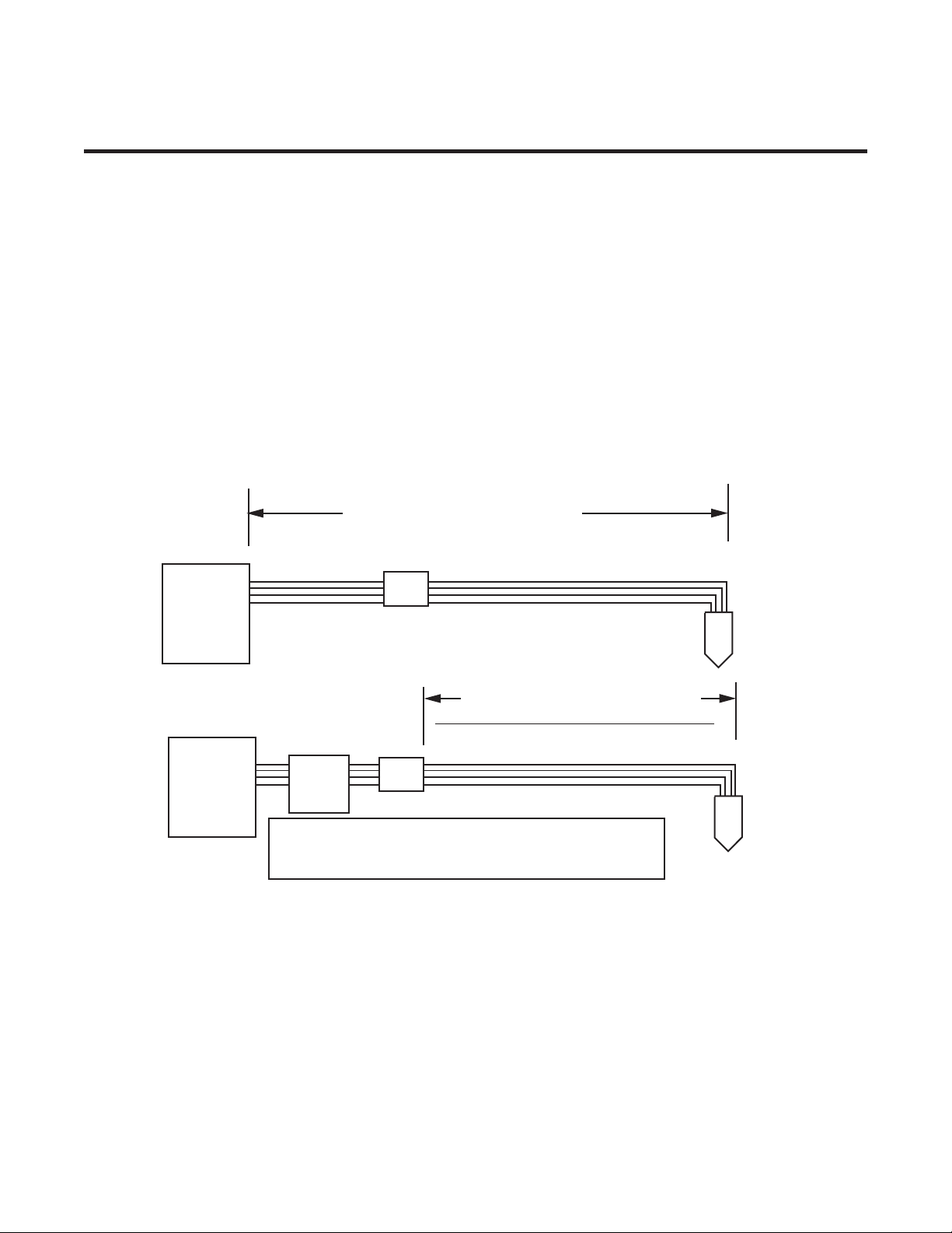
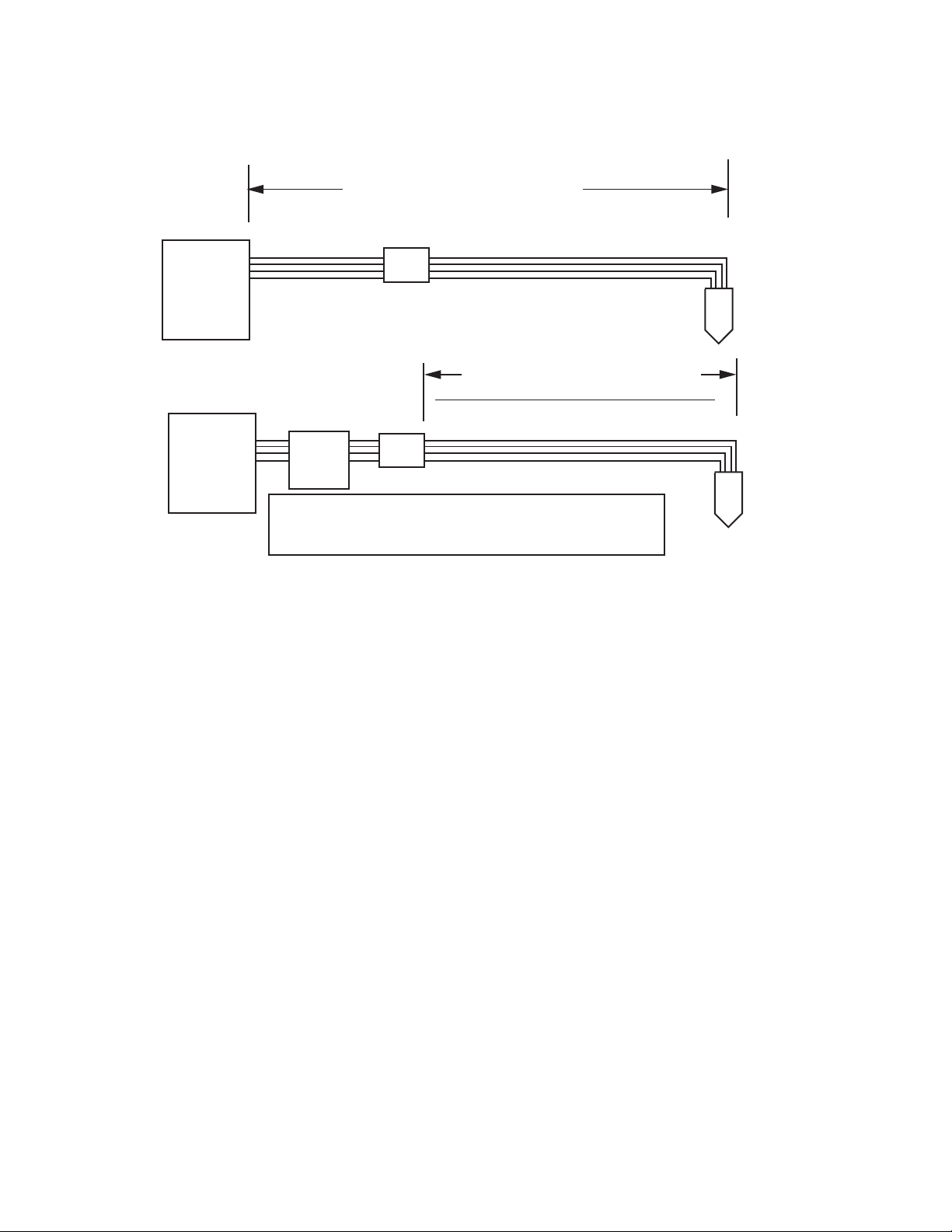
The XTTM-301 Torch is a direct replacement for the MaximizerTM torch on MerlinTM 1000 cutting systems. The XT-301
Torch can be connected to Maximizer torch leads up to 25' / 7.6 m long. Use only XT-301 Torch leads for installations
requiring leads longer than 25 ft / 7.6 m.
< 25’ / 7.6m: Use XT-301 Torch Head
and Maximizer Torch Leads
> 25’ / 7.6m: Use XT-301 Torch Head
and XT-301 Torch Leads
Merlin 1000
Power
Supply
Torch
Leads
XT-301
Torch
< 25’ / 7.6m: Use XT-301 Torch Head
and Maximizer Torch Leads
> 25’ / 7.6m: Use XT-301 Torch Head
and XT-301 Torch Leads
XT-301
Torch
Merlin 1000
Power
Supply
Art # A-07074
Remote
Arc
Starter
NOTE: Installations with Remote Arc Starter require installer
to reverse coolant lead connections at power supply bulkhead.
Refer to installation instructions for details.
Torch
Leads
The XT-301 Torch is available in a 180° configuration.
The XT-301 Torch is a liquid cooled torch. Two torch leads provide plasma and secondary ('shield') gas to the torch
head. The leads also provide a closed loop for the liquid coolant flow from the Power Supply.
Manual 0-4768 2-1 INTRODUCTION
Page 16
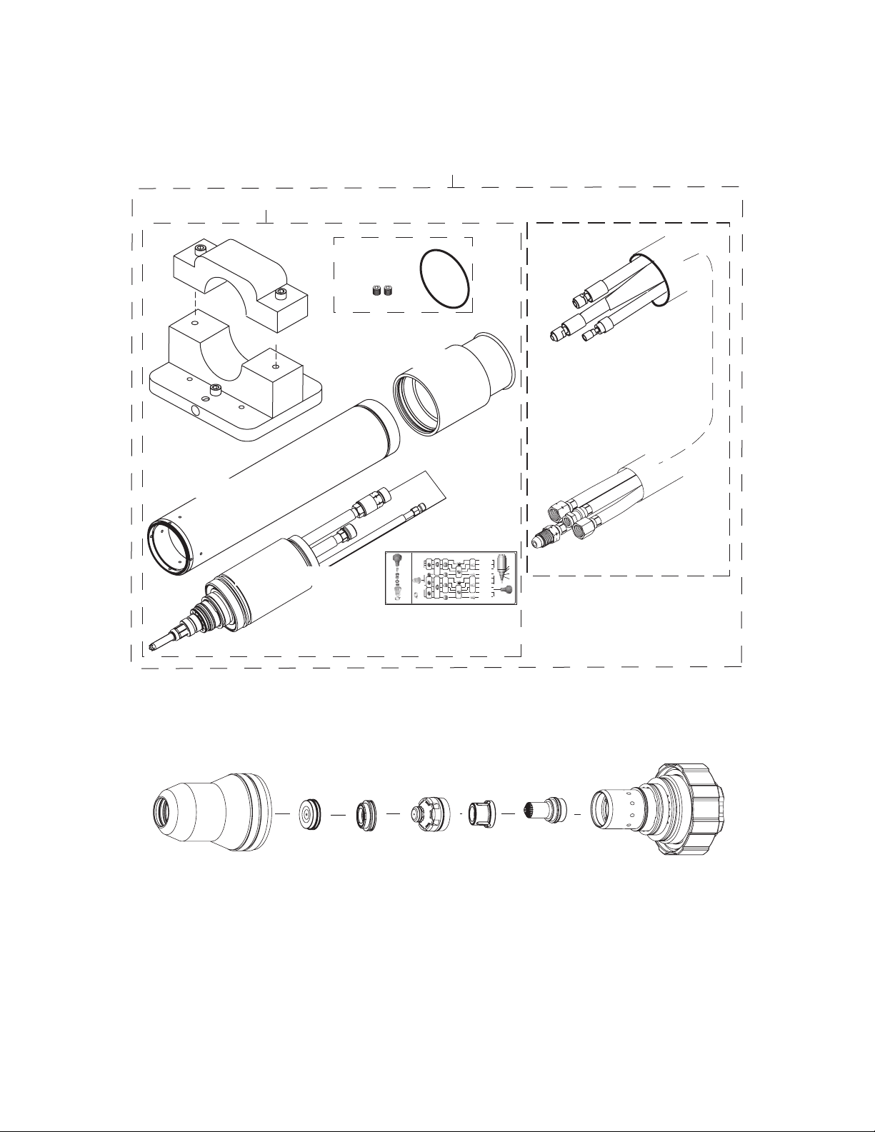
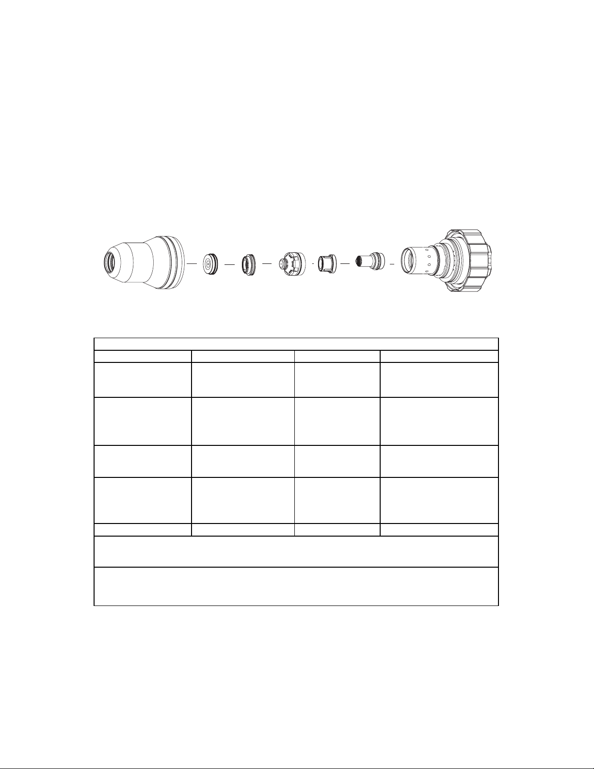
2.03 Torch Kit Contents
All Gases
35-1041
XT-301™ Conventional Plasma Torch
55A, MS
Air Plasma/Air Shield
Ohmic Sensor
9-9414
CARTRIDGE
ELECTRODE
PLASMA GAS
DISTRIBUTOR
TIP
SHIELD GAS
DISTRIBUTOR
SHIELD
OHMIC
SENSOR
SHIELD CUP
55-100A,
SS
23X4906 Rev AA
55A, MS
O2 Plasma/Air Shield
55A, SS
N2 Plasma/H2O Shield
55A, SS
Air Plasma/Air Shield
100A, MS
O2 Plasma/Air Shield
100A, MS
Air Plasma/Air Shield
100A, SS/Aluminum
Air Plasma/Air Shield
Cartridge
35-1020
100A, SS/Aluminum
N2 Plasma/H2O Shield
Electrodes
Plasma Gas
Distributors
All Gases
35-1041
55A,
MS/SS
55A, SS
35-1060
100A,
MS/SS
100A, SS
35-1062
Tips
Shield Gas
Distributors
55A,
MS/SS
55-100A, SS
35-1034
Shield Cup
35-1016
Shields
'O' Ring
Placement
8-0539
8-0534
8-0530
TORCH
HEAD
9-9041
100A, SS/Aluminum
H35 Plasma/N2 Shield
55A,
MS/SS
55A, SS
35-1078
100A,
MS/SS
100A, SS
35-1080
35-1041
or
35-1042
35-1041
or
35-1042
NO
OXYGEN
NO
OXYGEN
35-1051
35-1053
MS/SS
35-1069
35-1071
35-1272
35-1272
MS/SS
35-1025
100A,
MS/SS
35-1027
35-1034
35-1001
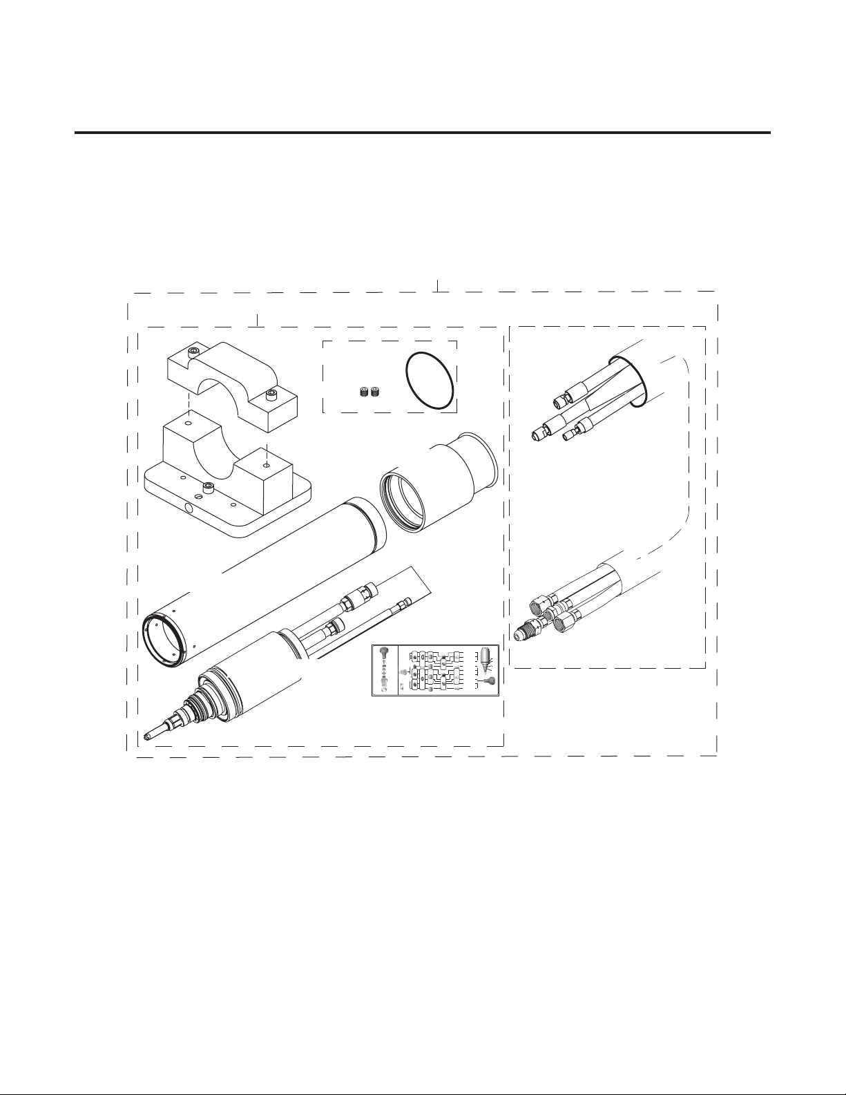
1: Torch Kit
Torch Clamp
Assembly
Mounting Tube
2: Torch and Leads Kits
Mounting Tube
Hardware Kit
End Cap
Torch Head Assembly
Torch operation requires these additional parts:
Art # A-04741
Shield Gas
Distributor
Shield Cap
Shield Cup
Parts Label
55A,
MS/SS
CARTRIDGE
35-1025
ELECTRODE
55-100A, SS
35-1034
PLASMA GAS
DISTRIBUTOR
100A,
TIP
MS/SS
SHIELD GAS
DISTRIBUTOR
Shield Cup
SHIELD
35-1016
35-1027
55-100A,
SS
SHIELD CUP
35-1034
OHMIC
Ohmic Sensor
SENSOR
9-9414
Shields
Tip
XT-301™ Conventional Plasma Torch
All Gases
55A,
MS/SS
55A,
35-1041
MS/SS
MS/SS
NO
35-1051
35-1069
OXYGEN
55A, SS
55A, SS
35-1060
35-1078
35-1272
35-1041
or
35-1042
100A,
100A,
MS/SS
All Gases
MS/SS
MS/SS
35-1041
NO
OXYGEN
35-1071
35-1053
100A, SS
100A, SS
35-1041
35-1062
35-1080
or
35-1272
35-1042
Plasma Gas
Shield Gas
Distributors
Electrodes
Tips
Distributors
Plasma Gas
Distributor
55A, MS
O2 Plasma/Air Shield
55A, MS
Air Plasma/Air Shield
55A, SS
N2 Plasma/H2O Shield
55A, SS
Air Plasma/Air Shield
100A, MS
O2 Plasma/Air Shield
100A, MS
Air Plasma/Air Shield
100A, SS/Aluminum
Air Plasma/Air Shield
100A, SS/Aluminum
N2 Plasma/H2O Shield
100A, SS/Aluminum
H35 Plasma/N2 Shield
TORCH
HEAD
35-1001
'O' Ring
Placement
9-9041
8-0539
8-0534
8-0530
Cartridge
35-1020
23X4906 Rev AA
Lead Packages, Lengths > 25 ft / 7.6 m
Art # A-07043
Electrode
Cartridge
INTRODUCTION 2-2 Manual 0-4768
Page 17
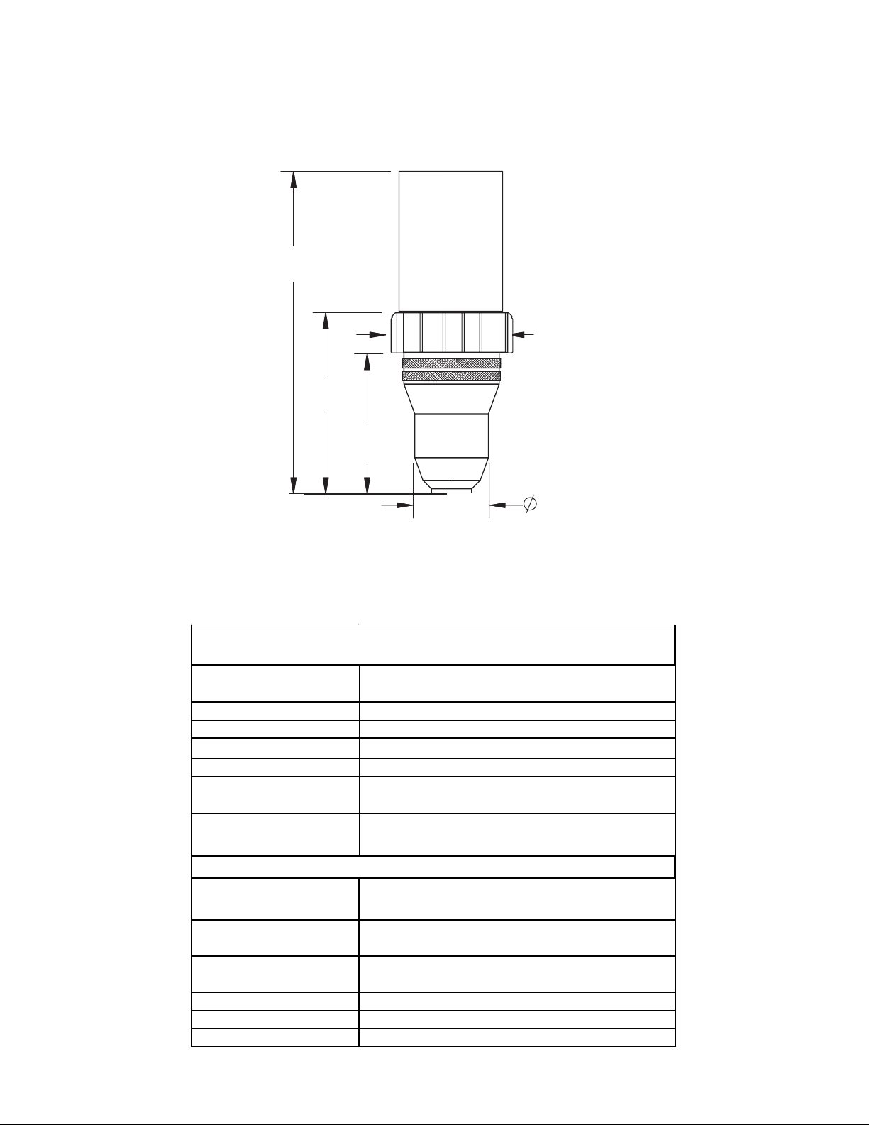
2.04 Specifications & Design Features
p
g
1. XTTM-301 Torch Configuration and Dimensions
6.30"
160.10 mm
3.54"
89.87 mm
2.74"
69.55 mm
Art # A-06257
2.39"
60.81 mm
1.49"
37.8 mm
2. Torch Ratings and Gas Specifications
When Used with Merlin 1000 Power Supply
Ambient
Temperature
Duty Cycle 100% @ 100 Amps
Maximum Current 100 Amps
Voltage (V
)500V
eak
Arc Striking Voltage 10kV
Current
Minimum Coolant
Flow Requirements
XT
Plasma Gases:
Shield Gases:
Operating Pressure
Maximum Input Press ure 135 psi / 9.3 bar
Gas flow 10 - 300 scfh
Power supply used with: Merlin 1000
TM
XT
-301 Torch Ratings
104° F
40° C
Up to 100 Amps, DC,
Straight Polarity (See Note)
0.9 gpm (3.4 lpm)
TM
-301 Torch Gas Specifications
Compressed Air, Oxygen,
Ar
on/Hydrogen (H35)
Compressed Air,
Nitrogen (N2)
90 psi ± 5 psi
6.2 bar ± 0.4 bar
Manual 0-4768 2-3 INTRODUCTION
Page 18
3. Cutting Range
Most materials up to 1 inch (25.4 mm)
Up to 1/2 inch (12.7 mm) for production speed cutting
4. Pierce Rating
1/2 inch (12.7 mm)
5. Transfer Distance
1/8 - 1/4 inch (3-6 mm)
6. Torch Parts
Shield Cup, Shield Cap, Secondary ('Shield') Gas Distributor, Tip, Plasma Gas Distributor, Electrode, Cartridge
Art # A-04741
Shield Cup
7. Gas Requirements
Gas Quality Minimum Pressure Flow
O2 (Oxygen)
N2 (Nitrogen)
Compressed
or Bottled Air
H35 (Argon-Hydrogen)
H35 = 35% Hydrogen,
65% Argon
Shield Gas
Distributor
Shield Cap
Plasma Gas
Tip
Distributor
Electrode
Gas Pressures, Flows, and Quality Requirements
99.5% Purity
(Liquid recommended)
90 psi
6.2 bar / 620 kPa
99.5% Purity
(Liquid recommended)
<1000 ppm O2, <32
90 psi
6.2 bar / 620 kPa
278 scfh (7872 l/h)
ppm H2O)
Clean, Dry,
Free of Oil (see Note 1)
99.995% Purity
(gas liquid
recommended)
90 psi
6.2 bar / 620 kPa
90 psi
6.2 bar / 620 kPa
Cartridge
83 scfh (2350 l/h)
82 scfh (2313 l/h)
77 scfh (2180 l/h)
H2O (Water) See Note 2 50 psi (3.5 bar) 3 - 9 gph (13 - 40 lph)
: The air source must be adequately filtered to remove all oil or grease. Oil or grease
Note 1
contamination from compressed or bottled air can cause fires in conjunction with oxygen.
: The tap water source does not need to be deionized, but in water systems with
Note 2
extremely high mineral content a water softener is recommended. Tap water with high levels of
particulate matter must be filtered.
8. Parts - In - Place (PIP)
The torch is designed for use with a power supply which senses coolant return flow to confirm that torch parts are
in place. If coolant return flow to the power supply is absent or insufficient the power supply will not provide
power to the torch. Coolant leakage from the torch also indicates that torch parts are absent or installed improperly.
9. Type of Cooling
Combination of gas stream through torch and liquid cooling.
INTRODUCTION 2-4 Manual 0-4768
Page 19
3.01 Kit Contents
All Gases
35-1041
XT-301™ Conventional Plasma Torch
55A, MS
Air Plasma/Air Shield
Ohmic Sensor
9-9414
CARTRIDGE
ELECTRODE
PLASMA GAS
DISTRIBUTOR
TIP
SHIELD GAS
DISTRIBUTOR
SHIELD
OHMIC
SENSOR
SHIELD CUP
55-100A,
SS
23X4906 Rev AA
55A, MS
O2 Plasma/Air Shield
55A, SS
N2 Plasma/H2O Shield
55A, SS
Air Plasma/Air Shield
100A, MS
O2 Plasma/Air Shield
100A, MS
Air Plasma/Air Shield
100A, SS/Aluminum
Air Plasma/Air Shield
Cartridge
35-1020
100A, SS/Aluminum
N2 Plasma/H2O Shield
Electrodes
Plasma Gas
Distributors
All Gases
35-1041
55A,
MS/SS
55A, SS
35-1060
100A,
MS/SS
100A, SS
35-1062
Tips
Shield Gas
Distributors
55A,
MS/SS
55-100A, SS
35-1034
Shield Cup
35-1016
Shields
'O' Ring
Placement
8-0539
8-0534
8-0530
TORCH
HEAD
9-9041
100A, SS/Aluminum
H35 Plasma/N2 Shield
55A,
MS/SS
55A, SS
35-1078
100A,
MS/SS
100A, SS
35-1080
35-1041
or
35-1042
35-1041
or
35-1042
NO
OXYGEN
NO
OXYGEN
35-1051
35-1053
MS/SS
35-1069
35-1071
35-1272
35-1272
MS/SS
35-1025
100A,
MS/SS
35-1027
35-1034
35-1001
These kit configurations are available:
1: Torch Kit
Torch Clamp
Assembly
SECTION 3:
INSTALLATION
2: Torch and Leads Kits
Mounting Tube
Hardware Kit
End Cap
Mounting Tube
Torch Head Assembly
Parts Label
55A,
MS/SS
CARTRIDGE
35-1025
ELECTRODE
55-100A, SS
35-1034
PLASMA GAS
DISTRIBUTOR
100A,
TIP
MS/SS
SHIELD GAS
DISTRIBUTOR
Shield Cup
SHIELD
35-1016
35-1027
55-100A,
SS
SHIELD CUP
35-1034
OHMIC
Ohmic Sensor
SENSOR
9-9414
Shields
XT-301™ Conventional Plasma Torch
All Gases
MS/SS
55A,
35-1041
MS/SS
NO
35-1051
OXYGEN
55A, SS
35-1060
35-1272
35-1041
or
35-1042
100A,
MS/SS
All Gases
MS/SS
35-1041
NO
OXYGEN
35-1053
100A, SS
35-1041
35-1062
or
35-1272
35-1042
Plasma Gas
Shield Gas
Distributors
Tips
Distributors
TORCH
HEAD
35-1001
55A, MS
55A,
O2 Plasma/Air Shield
MS/SS
'O' Ring
55A, MS
Placement
Air Plasma/Air Shield
9-9041
35-1069
55A, SS
8-0539
N2 Plasma/H2O Shield
55A, SS
35-1078
55A, SS
8-0534
Air Plasma/Air Shield
100A,
100A, MS
8-0530
MS/SS
O2 Plasma/Air Shield
100A, MS
Air Plasma/Air Shield
100A, SS/Aluminum
Air Plasma/Air Shield
35-1071
100A, SS/Aluminum
N2 Plasma/H2O Shield
100A, SS
Cartridge
35-1080
35-1020
100A, SS/Aluminum
H35 Plasma/N2 Shield
Electrodes
23X4906 Rev AA
Lead Packages, Lengths > 25 ft / 7.6 m
Art # A-07043
Manual 0-4768 3-1 INSTALLATION
Page 20
3.02 Kit Applications:
Merlin 1000
Power
Supply
Merlin 1000
Power
Supply
Art # A-07074
Remote
Starter
NOTE: Installations with Remote Arc Starter require installer
to reverse coolant lead connections at power supply bulkhead.
Refer to installation instructions for details.
< 25’ / 7.6m: Use XT-301 Torch Head
and Maximizer Torch Leads
> 25’ / 7.6m: Use XT-301 Torch Head
and XT-301 Torch Leads
Torch
Leads
< 25’ / 7.6m: Use XT-301 Torch Head
> 25’ / 7.6m: Use XT-301 Torch Head
Torch
Arc
Leads
XT-301
Torch
and Maximizer Torch Leads
and XT-301 Torch Leads
XT-301
Torch
3.03 Unpacking
The product is packaged and protected to prevent damage during shipping.
1. Unpack each item and remove all packing material.
2. Locate the packing list(s) and use the list to identify and account for each item.
3. Inspect each item for possible shipping damage. If damage is evident, contact your distributor and/or shipping
company before proceeding with installation.
INSTALLATION 3-2 Manual 0-4768
Page 21
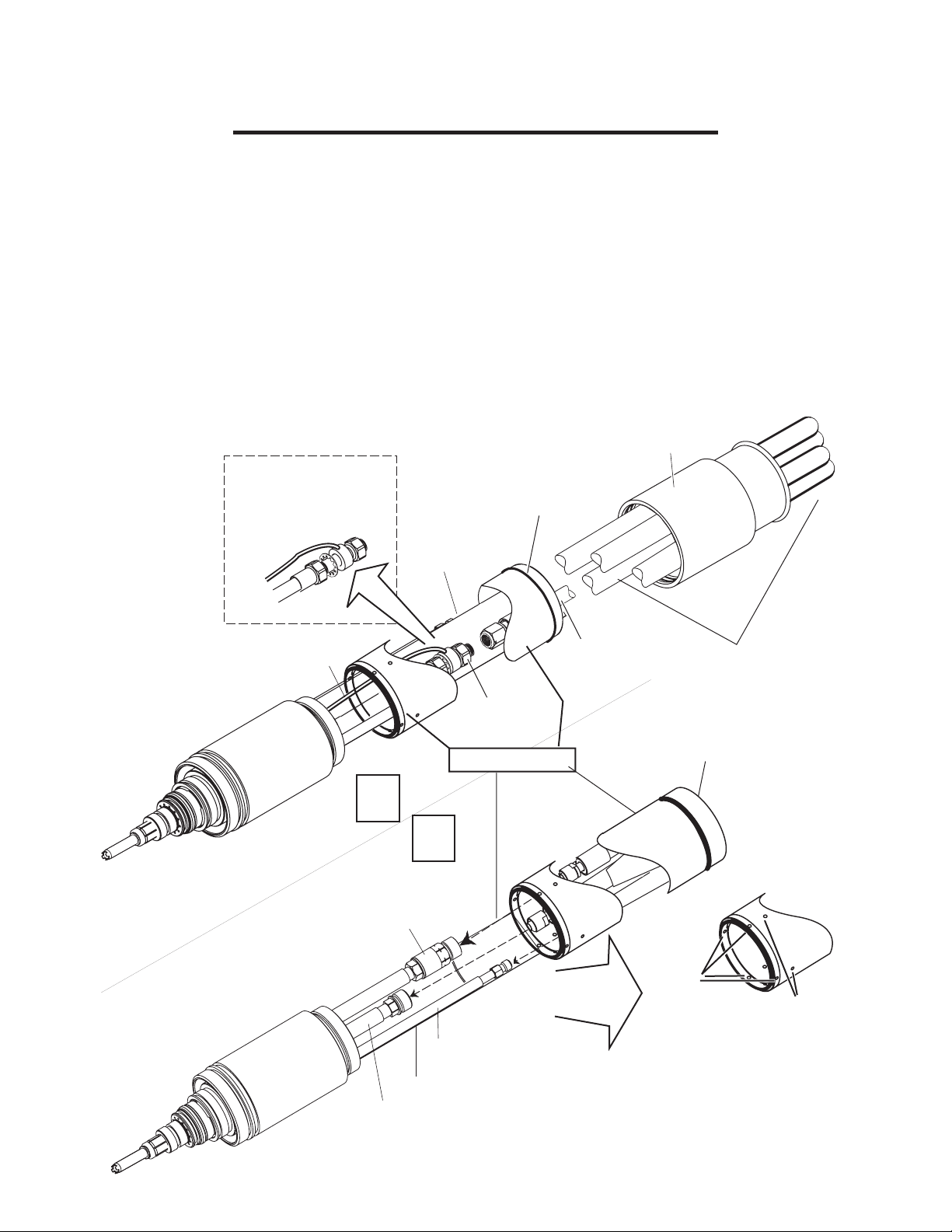
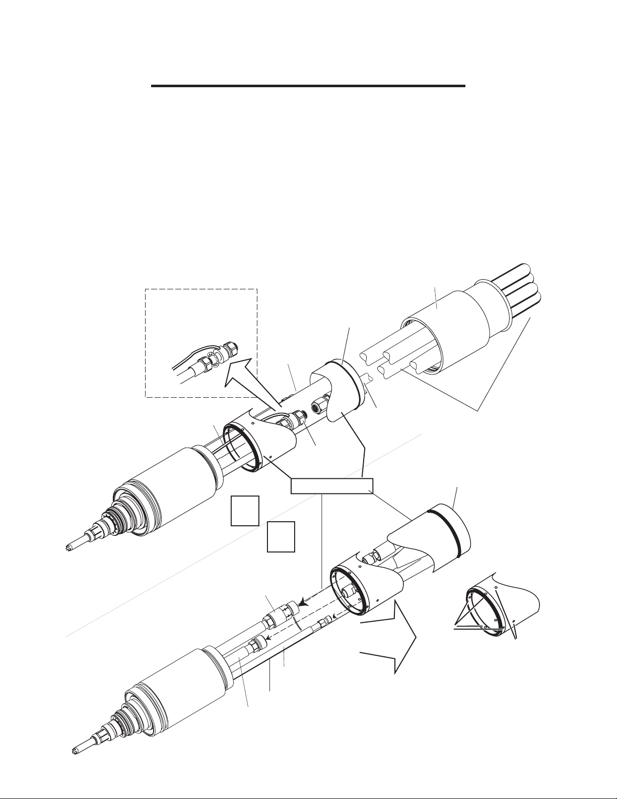
3.04 XT-301 Torch Head Installation on MaximizerTM Leads (up to 25' long)
The XT-301 torch head can be connected to Maximizer leads up to 25' / 7.6 m long. For applications with longer leads,
replace the Maximizer torch leads with XT-301 leads. Connect the Torch head to existing Maximizer leads as follows:
WARNING
Disconnect primary power at the source before disassembling the torch
or torch leads.
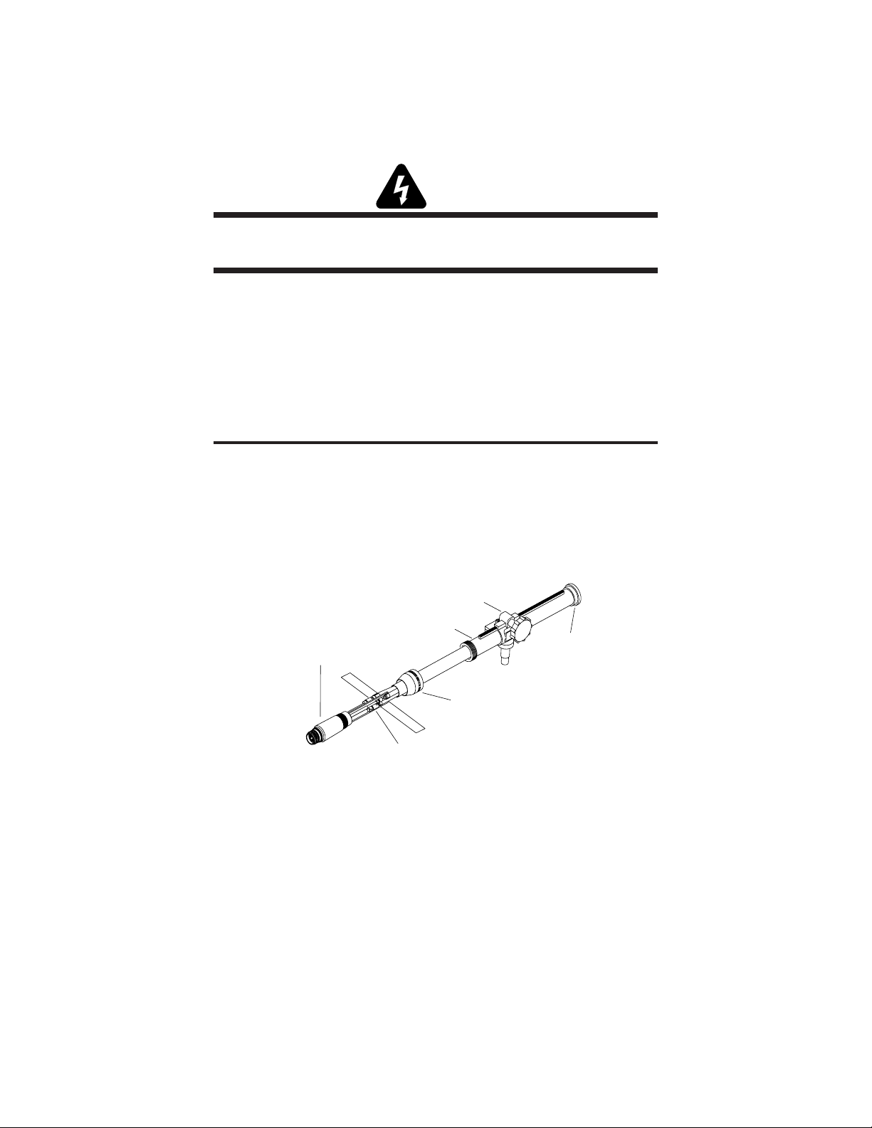
A. Remove Maximizer Torch and Mounting Assembly
1. Remove the torch, positioning tube, and pinion assembly from -its support.
2. Locate the shrink-on tubing at the back end of the torch positioning tube. Remove the shrink-on tubing from
the torch lead sleeving being careful not to damage the lead assembly underneath.
3. Under the shrink-on tubing remove the tape from the torch lead sleeving and slide the sleeving back (see
NOTE).
NOTE
The positioning tube will not slide over the torch lead sleeving.
4. Unscrew the positioning tube and the torch adaptor from the torch head assembly. Slide the positioning tube,
torch adapter, and pinion assembly back over the leads to expose the four gas and coolant connectors..
5. Disconnect the plasma (+), secondary, coolant supply (-), and coolant return connectors to allow removal of
the torch head.
Pinion Assembly
Machine
Torch Head
Positioning Tube
Lead Connections
Bushing
Torch Adaptor
A-00663
Maximizer Torch Mounting Assembly
6. Slide the torch adapter, positioning tube, bushing, and end cap off the torch leads.
7. Set the Maximizer torch and mounting equipment aside in a secure location.
Manual 0-4768 3-3 INSTALLATION
Page 22
B. Install XT-301 Torch
NOTE
Handle the torch head carefully to avoid damage. The installer may choose
to follow Section 3.07, Installing Consumable Parts, before installing the
torch head. This will provide additional protection to the coolant tube on
the torch head during installation.
1. Install the torch clamp assembly included in this kit, in place of the pinion removed previously.
2. Slide the end cap up onto the torch leads.
3. Remove and discard the protective end caps from the Mounting Tube.
4. Install the O-ring included in this kit in the groove at the upper end of the Mounting Tube.
5. Slide the positioning tube up onto the torch leads, far enough to allow access to the lead connection fittings.
6. Connect the XT-301 torch head to the Maximizer leads as shown.
End Cap
Shown to illustrate
assembly order only;
parts must remain
secured tightly.
O-Ring
Pilot Lead
Insulating Paper
1
2
Coolant Return
Check Valve
and Connector
Plasma Lead
Connector
Positioning Tube
Positioning Tube
Plasma Lead
Detail
Torch Leads
O-Ring
Threaded
Holes
Drain Holes
Shield ('Secondary')
Gas Connector
Insulating Paper
Coolant Supply Connector
Art # A-06258
INSTALLATION 3-4 Manual 0-4768
Page 23

7. Press the Torch Head Assembly upward to connect to the positioning tube. Pull the leads back as needed to
ensure a proper fit through the positioning tube. Hold the Torch Head Assembly stationary; rotate the positioning tube to thread it onto the Torch Head. Install set screws from the hardware kit in any two of the threaded
holes at the bottom of the positioning tube, to fasten the head assembly to the positioning tube.
CAUTION
Ensure that the leads do not twist within the positioning tube. Leads
must lie as shown in the installation sketch.
8. Press the end cap downward on the positioning tube to cover and engage the O-Ring at the top of the
positioning tube.
9. Secure the positioning tube to the torch clamp.
10. Secure the torch clamp to its mounting device. If not done previously, refer to Section 3.07 for details on
installing torch consumable parts.
Manual 0-4768 3-5 INSTALLATION
Page 24
3.05 Connecting XT-301 Torch and Torch Leads (over 25' long) to Merlin 1000
This section details connecting the XT-301 Torch and XT-301 Torch leads directly to the Merlin 1000 Power supply.
Refer to Section 3.06 for connections to the optional Merlin Remote Arc Starter.
A. Remove Maximizer Torch and Leads
1. Remove the torch and pinion assembly (with torch leads) from its support. Set the assembly aside in a secure
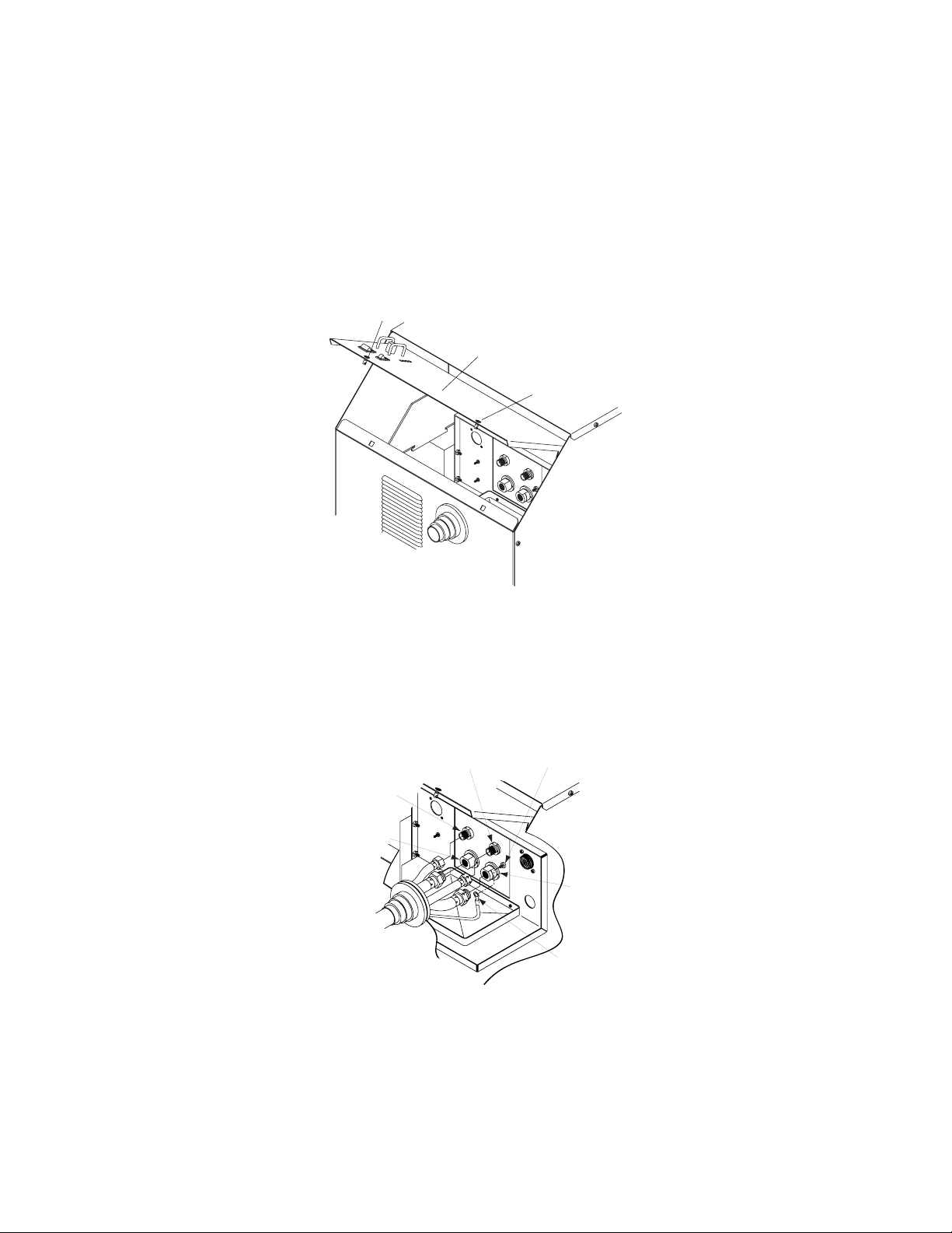
location.
2. On the power supply, turn the two latch screws fastening the Control / Access Panel to the power supply.
Latch Screw
Control/Access Panel
Latch Screw
A-02165
3. Open the Access Panel.
4. Disconnect the torch leads, including the control cable connector and shield leads, from the power supply
bulkhead panel. The first illustration shows leads with single shielding; the second illustration shows leads
with double shielding
Plasma (+)
Gas
Secondary
Gas
Coolant
Supply (-)
A-02856
Torch Leads
Shield Stud
Coolant
Return
Ring Lug
Single-shielded Leads Connections
INSTALLATION 3-6 Manual 0-4768
Page 25
Torch Leads
Shield Stud
(for OUTER Shields)
Power
Supply
Chassis
GREEN / YELLOW Shield
Wires with Ring Lugs
Secondary
Gas
Plasma (+)
Coolant
Supply (-)
Gas
Torch Leads
Shield Stud
(for INNER Shields)
Coolant
Return
Control Cable
Connector
Torch
Bulkhead
Panel
CNC Control
Cable
Art # A-07073
RED Shield Wires
With Ring Lugs
Double-shielded Leads Connections
5. Carefully remove the torch leads through the rubber boot on the power supply front panel. Feed the control
cable connector through the boot last, as there will not be enough room for it to pass through the boot if the
other leads are in the boot.
Manual 0-4768 3-7 INSTALLATION
Page 26

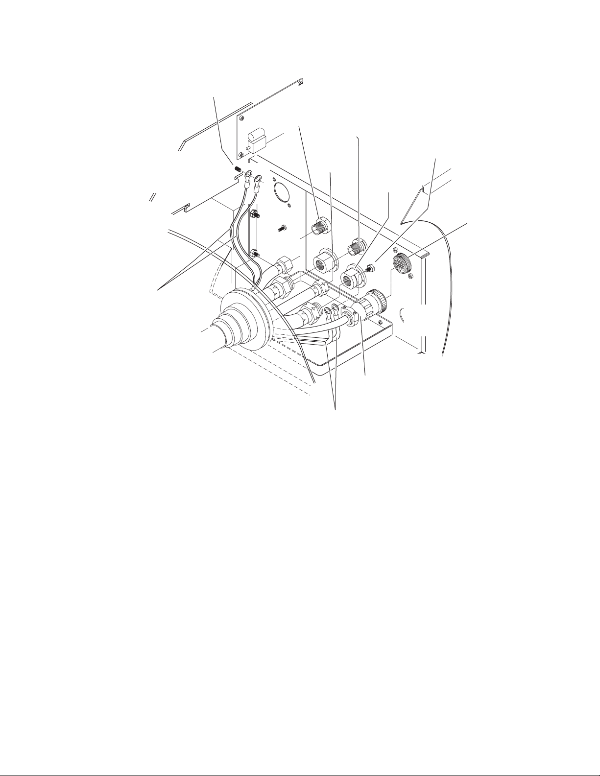
B. Connect XT-301 Leads to Merlin 1000 Power Supply
WARNING
Disconnect primary power at the source before disassembling the torch
or torch leads.
1. Feed the connector on the end of the CNC Control Cable through the rubber boot on the front panel of the
Power Supply (see NOTE).
NOTE
Feed the Control Cable through the rubber boot first as there will not be
enough space inside the rubber boot for the connector if the Coolant and
Gas Leads have been fed through the rubber boot first.
2. Connect the CNC Control Cable connector to the Control Cable connector on the Torch Bulkhead Panel.
3. Feed the ends of the Torch Leads through the rubber boot.
4. Refer to the illustration. The Leads Assembly includes two leads shields; each shield includes two ring-tongue
connectors. Connect the Torch Leads Shield Wires as follows:
a. Remove one nut and star washer from the torch leads shield stud on the Torch Bulkhead Panel.
b. Place the ring lugs from the inner (RED) Torch Leads Shield Wires over the shield stud on the Torch
Bulkhead Panel.
c. Secure the wires with the nut and star washer.
d. Place the ring lugs from the outer (GREEN / YELLOW) Torch Leads Shield Wires over the shield stud on
the power supply chassis.
e. Use the nut and star washer previously removed from the torch leads assembly to secure the wires to the
shield stud on the power supply chassis.
5. Connect torch coolant and gas leads to connectors on the Torch Bulkhead Panel.
6. Close the Access Panel and turn the two latching screws.
INSTALLATION 3-8 Manual 0-4768
Page 27
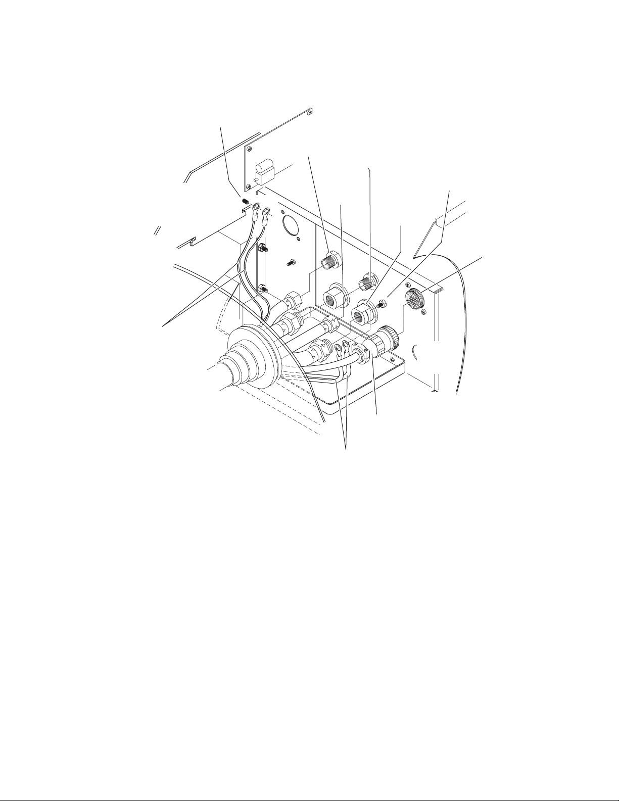
Torch Leads
Shield Stud
(for OUTER Shields)
Power
Supply
Chassis
GREEN / YELLOW Shield
Wires with Ring Lugs
Secondary
Gas
Plasma (+)
Coolant
Supply (-)
Gas
Torch Leads
Shield Stud
(for INNER Shields)
Coolant
Return
Control Cable
Connector
Torch
Bulkhead
Panel
CNC Control
Cable
Art # A-07073
RED Shield Wires
With Ring Lugs
Torch Leads Connections to Merlin 1000
Manual 0-4768 3-9 INSTALLATION
Page 28
B. Connect XT-301 Torch Head to XT-301 Torch Leads
NOTE
Handle the torch head carefully to avoid damage. The installer may choose
to follow Section 3.07, Installing Consumable Parts, before installing the
torch head. This will provide additional protection to the coolant tube on
the torch head during installation.
1. Install the torch clamp assembly included in this kit, in place of the pinion removed previously.
2. Slide the end cap up onto the torch leads.
3. Remove and discard the protective end caps from the Mounting Tube.
4. Install the O-ring included in this kit in the groove at the upper end of the Mounting Tube.
5. Slide the positioning tube up onto the torch leads, far enough to allow access to the lead connection fittings.
6. Connect the XT-301 torch head to the Maximizer leads as shown.
End Cap
Shown to illustrate
assembly order only;
parts must remain
secured tightly.
O-Ring
Pilot Lead
Insulating Paper
1
2
Coolant Return
Check Valve
and Connector
Plasma Lead
Connector
Positioning Tube
Positioning Tube
Plasma Lead
Detail
Torch Leads
O-Ring
Threaded
Holes
Drain Holes
Shield ('Secondary')
Gas Connector
Insulating Paper
Coolant Supply Connector
Art # A-06258
INSTALLATION 3-10 Manual 0-4768
Page 29

7. Press the Torch Head Assembly upward to connect to the positioning tube. Pull the leads back as needed to
ensure a proper fit through the positioning tube. Hold the Torch Head Assembly stationary; rotate the positioning tube to thread it onto the Torch Head. Install set screws from the hardware kit in any two of the threaded
holes at the bottom of the positioning tube, to fasten the head assembly to the positioning tube.
CAUTION
Ensure that the leads do not twist within the positioning tube. Leads
must lie as shown in the installation sketch.
8. Press the end cap downward on the positioning tube to cover and engage the O-Ring at the top of the
positioning tube.
9. Secure the positioning tube to the torch clamp.
10. Secure the torch clamp to its mounting device. If not done previously, refer to Section 3.07 for details on
installing torch consumable parts.
Manual 0-4768 3-11 INSTALLATION
Page 30

3.06 Connecting XT-301 Torch and Torch Leads to Remote Arc Starter
The Torch Leads connect to a bulkhead inside the Remote Arc Starter. In installations with torch leads less than 25
feet / 7.6 m long, connect the XT-301 Torch Head to Maximizer leads as in Section 3.04-B. In installations with torch
leads longer than 25 feet / 7.6 m, remove the Maximizer torch leads. Connect the XT-301 Torch Leads to the Remote
Arc Starter as follows:
WARNING
Disconnect primary power at the source before disassembling the torch
or torch leads.
A. Disconnect Maximizer Torch from Remote Arc Starter
1. Remove the cover from the Remote Arc Starter.
Cover
Art # A-07059
INSTALLATION 3-12 Manual 0-4768
Page 31

2. Disconnect the torch leads from the bulkhead panel inside the remote arc starter. The left illustration shows
single-shielded leads connections; the right illustration shows double-shielded leads connections.
Coolant
Return
Coolant Supply (-)
Left-Hand Thread
Outer (GREEN /
YELLOW)
Torch Lead
Shields
External Ground
(Customer Supplied)
A-02282
Coolant
Return
Coolant Supply (-)
Left-Hand Thread
Inner (RED) Torch
Lead Shields
Plasma Gas (+)
Left-Hand Thread
Secondary Gas
Torch Leads
Torch Lead Shield
Secondary Gas
Plasma Gas (+)
Left-Hand Thread
Torch Leads
Art # A-04002
Single-Shielded Maximizer Leads Connections Double-Shielded Maximizer Leads Connections
3. Carefully remove the torch leads through the boot on the Remote Arc Starter.
Manual 0-4768 3-13 INSTALLATION
Page 32

B. Connect XT-301 Torch Leads to Remote Arc Starter
1. Connect the torch leads connectors to the bulkhead connections per the following figure.
CAUTION
If the Arc Starter Box does not include a drilled hole in the front panel as
shown below for the outer (GREEN / YELLOW) torch lead shields, perform the following steps:
• Drill a hole in the area shown.
• Scrape both sides of the front panel down to bare metal around the hole (to a diameter of ± 3/4" / 19 mm).
• Provide hardware as shown to secure the outer (GREEN / YELLOW) torch shield leads to the Arc Starter
Box.
• Use the same hardware to connect a customer-supplied external ground from the Arc Starter Box to an
earth ground.
Coolant
Inner (RED) Torch
Lead Shields
Return
Coolant Supply (-)
Left-Hand Thread
Outer (GREEN /
YELLOW)
Torch Lead
Shields
Plasma Gas (+)
Left-Hand Thread
Secondary Gas
External Ground
(Customer Supplied)
Torch Leads
Art # A-04002
Torch Leads Connections to Arc Starter Box
2. Connect the inner shield leads with red wires and ring terminals to the mounting stud on the bulkhead panel.
3. Remove the nut and bolt mounted to the Remote Arc Starter front panel. Connect the outer shield leads with
green/yellow wires and ring terminals to the mounting stud on the inside of the front panel. Secure the stud to
the front panel with a hex nut. Connect a customer-supplied external ground wire to the stud, outside the front
panel, and secure with a hex nut. Connect the other end of this ground wire to a properly-installed earth
ground.
INSTALLATION 3-14 Manual 0-4768
Page 33

C. Reverse Coolant Leads at the Power Supply
1. Remove the power supply left side panel.
Art # A-07076
Remove power supply left side panel
2. On the torch bulkhead panel, disconnect and reverse the coolant leads.
#6 JIC Fitting
#6 JIC Fitting
Original Coolant Return Lead
Reverse coolant leads
3. Re-install the power supply left side panel.
Original Coolant Supply Lead
Art # A-07077
Manual 0-4768 3-15 INSTALLATION
Page 34

D. Install XT-301 Torch
NOTE
Handle the torch head carefully to avoid damage. The installer may choose
to follow Section 3.07, Installing Consumable Parts, before installing the
torch head. This will provide additional protection to the coolant tube on
the torch head during installation.
1. Remove the Maximizer torch and pinion assembly from its support. Set the assembly aside in a secure
location.
2. Install the torch clamp assembly included in this kit, on the torch positioning tube..
3. Slide the XT-301 end cap up onto the torch leads.
4. Remove and discard the protective end caps from the Mounting Tube.
5. Install the O-ring included in this kit in the groove at the upper end of the Mounting Tube.
6. Slide the positioning tube up onto the torch leads, far enough to allow access to the lead connection fittings.
7. Connect the XT-301 torch head to the XT-301 leads as shown.
8. Press the Torch Head Assembly upward to connect to the positioning tube. Pull the leads back as needed to
ensure a proper fit through the positioning tube. Hold the Torch Head Assembly stationary; rotate the positioning tube to thread it onto the Torch Head. Use hardware provided to fasten the head assembly to the positioning tube.
CAUTION
Ensure that the leads do not twist within the positioning tube. Leads
must lie as shown in the installation sketch.
9. Press the end cap downward on the positioning tube to cover and engage the O-Ring at the top of the
positioning tube.
INSTALLATION 3-16 Manual 0-4768
Page 35

Shown to illustrate
assembly order only;
parts must remain
secured tightly.
End Cap
O-Ring
Insulating Paper
Pilot Lead
Plasma Lead
Connector
Positioning Tube
1
2
Coolant Return
Check Valve
and Connector
Shield ('Secondary')
Gas Connector
Insulating Paper
Coolant Supply Connector
Plasma Lead
Positioning Tube
Detail
Torch Leads
O-Ring
Threaded
Holes
Drain Holes
Art # A-06258
10. The lower end of the Mounting Tube includes four threaded holes. Install an Allen set screw from the hardware
kit in any of the threaded holes to secure the Torch Head Assembly to the Mounting Tube.
11. Fasten the positioning tube into the torch clamp. Slide the leads end cap down onto the torch positioning tube.
Ensure that the end cap engages the O-ring at the top of the positioning tube.
12.Install the shield cup, and cartridge assembly (including consumables) onto the torch head.
Manual 0-4768 3-17 INSTALLATION
Page 36

3.07 Install Consumable Torch Parts (All Applications)
1. Check the appropriate cut chart for the right combination of parts for the cutting application.
2. Install the consumable parts as follows to ensure proper operation. These steps will help ensure that parts are
seated correctly.
Electrode
Plasma Gas
Distributor
Tip
Shield Gas
Distributor
Shield Cap
3: Thread Shield Cup onto Cartridge
1: Stack Parts
O-Ring
on Tip
2: Press Cartridge onto Stacked Parts
No Gaps
Between Parts
Cartridge Covers
O-Ring
on Torch Tip
4: Check Shield Cap Protrusion
Shield Cup
Shield Cap
Shield Cap Protrudes
0.063-0.083" (1.6 - 2.1 mm)
Art # A-04873
3. Stack the consumable parts together.
4. Insert the stack of consumable parts into the cartridge. Ensure that the large O-ring on the torch tip fits
completely into the cartridge. If any part of the O-ring protrudes from the cartridge, the parts are not seated
properly.
INSTALLATION 3-18 Manual 0-4768
Page 37

5. Use the removal tool to hold the cartridge assembly, while turning the shield cup onto the cartridge
assembly. When this group is fully assembled, the shield should protrude from the front of the shield cup
0.063" to 0.083" (1.6 - 2.1 mm). Without this protrusion the shield cup is not properly tightened onto the
cartridge assembly.
Cartridge Tool
Assembled Cartridge
Art # A-04344
Shield Cup
Installing Shield Cup Onto Cartridge
6. Take the removal tool off the cartridge. Fit the cartridge assembly onto the torch head. The cartridge should
seal to the large O-ring on the torch body as shown. If the cartridge does not seal on the O-ring, the cartridge
is not fully tightened.
CAUTION
Do not force the cartridge if it will not fully tighten. Remove the cartridge
and gently clean the threads on the torch head body with a wire brush.
Apply oxygen-compatible lubricant (supplied with the torch) to the threads.
Torch Head
Assembled Cartridge
Art # A-03893
Installing Assembled Cartridge Onto Torch Head
Manual 0-4768 3-19 INSTALLATION
Page 38

7. Connect the wire lead from the height finder to the ohmic clip if using ohmic torch height sensing.
NOTE
Ohmic sensing is not recommended with water shield (secondary). Water on the plate interferes electrically with the ohmic sensing system.
8. Confirm proper parts assembly as shown.
Torch Head
0.063 - 0.083"
(1.6 - 2.1 mm)
Protrusion
9. Slide the ohmic clip over the shield cup if using ohmic torch height sensing.
Torch Head O-Ring
Art # A-07202
Ohmic Clip
10. Connect the wire lead from the height finder to the ohmic clip.
A-03393
INSTALLATION 3-20 Manual 0-4768
Page 39

SECTION 4:
OPERATION
4.01 Introduction
This Section provides a description of the XTTM-301 Torch
followed by operating procedures.
4.02 Functional Overview
The Torch operates with the Merlin® 1000 Power Supply
to provide a plasma cutting system which can cut most
metals from gauge thickness up to 1 inch (25.4 mm).
4.03 Getting Started
Follow this procedure at the start of each shift:
WARNING
Disconnect primary power at the source before assembling or disassembling stacked modules, individual modules, torch parts, or torch and leads assemblies.
A. Torch Parts
Check the torch for proper assembly. Install proper
torch parts for the desired application (refer to Section 6.05, Torch Parts Selection).
B. Input Power
1. Check the power source for proper input voltage.
2. Make sure that the Power Supply in the system is
set for the proper voltage (refer to Power Supply
Operating Manual for connections or adjustments).
E. Purge System
On the Power Supply place the ON/OFF switch to the
ON position. An automatic gas purge (pre-flow) will
remove any condensation that may have accumulated
in the torch and leads while the system was shut
down. The torch cannot be activated during the purge
cycle (pre-flow). After the purge is complete, if the
RUN/SET switch is in SET position, gas will flow. If
the switch is the in RUN position there will be no gas
flow.
F. Current Output Level
Set the desired current output level on the Power Supply for the desired operation.
NOTE
DO NOT exceed the amperage rating of the Torch
Parts (consumables).
G. Pressure And Flow Settings
Make the pressure and flow settings at the Gas Control Panel on the Plasma Power Supply.
NOTES
Refer to appropriate Plasma Power Supply Operating Manual for instructions on setting gas flows.
Refer to Cutting Speed Charts in the Appendix for
recommended gas pressures and flows for the material being cut.
H. Ready for Operation
Return the RUN/SET switch to RUN position.
The system is now ready for operation.
NOTE
Refer to Appendix 1 for a detailed block diagram of
the Sequence Of Operation.
3. Close main disconnect switch or plug unit in to
supply primary power to the system.
C. Work Cable
Check for a solid work cable connection to the workpiece.
D. Gas Supplies
Select desired gas supplies. Make sure gas sources
meet requirements (refer to Section 2.03, Specifications & Design Features). See the Appendix for gas
selection guidance. Check connections and turn gas
supplies on.
Manual 0-4768 4-1 OPERATION
Page 40

4.04 Torch Parts Selection
The metal to be cut and the plasma and secondary (shield) gases determine the torch parts to be used.
Torch parts:
Shield Cup, Shield Cap, Secondary (Shield) Gas Distributor, Tip, Plasma Gas Distributor, Electrode, Cartridge
Art # A-04741
Shield Gas
Distributor
Shield Cap
Shield Cup
Plasma Gas
Tip
Distributor
Electrode
Cartridge
CAUTION
Do not interchange parts. Make sure all parts in the torch correspond with the plasma and secondary in use.
Manual 0-4768 4-2 OPERATION
Page 41

Cartridge
35-1020
Art # A-06084
55A
Gases
Air - Air
Plasma and Shield
Electrodes
Plasma Gas
Tips
O2 - Air
35-1069
Distributors
35-1051
Mild Steel
100A
Air - Air
O2 - Air
35-1071
35-1041
35-1053
55A
Air - Air
35-1078
35-1060
Aluminum
Stainless Steel /
100A
H35 - N2
35-1080
N2 - H2O
35-1089
35-1041
35-1062
Air - Air
35-1053
35-1071
Shield Gas
Distributors
Shields
Manual 0-4768 4-3 OPERATION
35-1025
35-1272
35-1027
Shield Cup
35-1016
35-1272
35-1034
Ohmic Sensor
9-9414
35-1027
Page 42

4.05 Torch Maintenance
A. Consumable Removal
1. Use the removal tool to hold the Shield Cup & Cartridge Assembly stationary. Turn the Shield Cup to remove it
from the Cartridge Assembly.
Cartridge Tool
Assembled Cartridge
Art # A-04344
Shield Cup
2. Take the Removal Tool off the back of the Cartridge Assembly. Use the removal tool to push the consumable
parts out of the Cartridge.
Cartridge Tool
Shield Cup
Assembled Cartridge
Art # A-04035
Manual 0-4768 4-4 OPERATION
Page 43

B. O-Ring Lubrication
Lubricate all three O-Rings on the Cartridge Assembly and all three O-Rings on the Torch Head periodically with
Thermal Dynamics No. 9-4893 O-Ring Lubricant. Remove the snap ring on the cartridge assembly and slide the
locking ring downward for access to the O-Ring under the locking ring.
CAUTION
Use only Thermal Dynamics No. 9-4893 O-Ring Lubricant (Christo Lube MCG-129) with this torch part. Use of
other lubricants may cause irreparable damage to the torch.
Inner O-Ring (Cat. No. 8-0545)
Location (Under Locking Ring)
O-Ring, Cat. No. 8-0544
O-Ring, Cat. No. 8-0540
Cartridge Assembly
Snap Ring
Art # A-04071
O-Rings
Cat. No. 9-9041
Cat. No. 8-0539
Cat. No. 8-0534
Cat. No. 8-0530
Torch Head
Art # A-04066
Manual 0-4768 4-5 OPERATION
Page 44

C. Parts Wear
Replace the Gas Distributor if it is charred or cracked.
Replace the Gas Distributor if the flange is damaged in any way.
Replace the tip and/or electrode if they are worn.
Good Tip
Worn Tip
Good Electrode
Worn Electrode
Art # A-04745
Manual 0-4768 4-6 OPERATION
Page 45

D. Torch Consumables Installation
WARNINGS
1. Install the consumables as follows:
Do not install consumables into the Cartridge
while the Cartridge is attached to the Torch Head.
Keep foreign materials out of the consumables and Cartridge.
Handle all parts carefully to avoid damage,
which may affect torch performance.
Art # A-03887
Electrode
Plasma Gas
Distributor
Tip
Shield Gas
Distributor
Shield Cap
3: Thread Shield Cup onto Cartridge
1: Stack Parts
O-Ring
on Tip
2: Press Cartridge onto Stacked Parts
No Gaps
Between Parts
Cartridge Covers
O-Ring
on Torch Tip
4: Check Shield Cap Protrusion
Shield Cup
Shield Cap
Shield Cap Protrudes
0.063-0.083" (1.6 - 2.1 mm)
Art # A-04873
Manual 0-4768 4-7 OPERATION
Page 46

2. Remove the Removal Tool from the Cartridge and install the assembled Cartridge onto the Torch Head.
CAUTION
The cartridge assembly must cover the O-Ring on the torch head.
Do not force the cartridge if it will not tighten fully. Remove the cartridge assembly and gently clean the threads on
the torch head with a wire brush. Apply oxygen-compatible lubricant (supplied with the torch) to the threads.
Torch Head
0.063 - 0.083"
(1.6 - 2.1 mm)
Protrusion
Torch Head O-Ring
Art # A-07202
Installing Assembled Cartridge Onto Torch Head
3. Slide the ohmic clip over the shield cup if using ohmic torch height control sensing.
NOTE
Ohmic height sensing is not recommended with water secondary ('shield'). Water on the plate interferes electrically
with the ohmic sensing circuit.
Ohmic Clip
A-03393
4. Connect the wire lead from the height finder to the ohmic clip.
Manual 0-4768 4-8 OPERATION
Page 47

E. Coolant Leak Trouble-Shooting
Never operate the system if coolant leaks from the torch. A steady drip indicates that torch parts are damaged or
installed improperly. Operating the system in this condition can damage the torch head. Refer to the following chart
for guidance on coolant leakage from the torch head.
Torch leaks
Are Torch
Consumable Parts
Installed?
Ye s
Are Parts New
or Used?
New
Are Parts fully
assembled into
the Torch?
Unsure?
Disassembly fully
and re-assemble
the Torch Properly.
See Installation Manual.
No
Ye s
Used
Leaking from
Coolant Supply or
Coolant Return?
Is the Torch Damaged?
Yes
Replace Torch Head
Order Coolant
Return
Supply
The parts probably are worn out.
See chart for approximate life expectancy.
The torch may be damaged. See page
to determine if head damage has occurred.
Remove and Lubricate
all O-rings on Torch Head,
No
Yes
Consumables Cartridge,
and Consumables.
Re-assemble Torch.
Replace Consumable
Cartridge and Shield Cup.
Torch still leaks?
Check Valve
Kit 9-4846
Order Coolant
Tube Replacement Kit
Still leaks?
Yes
Amperage Plasma Gas Recommended Wear Depth
Torch Tips
for Replacement
O2 0.04 1
55
Air 0.08 2
O2 0.04 1
100
H35 0.08 2
Inch mm
Art # A-06403
Manual 0-4768 4-9 OPERATION
Page 48

4.06 Cut Quality
NOTE
Cut quality depends heavily on set-up and parameters such as torch standoff, alignment with the workpiece, cutting
speed, gas pressures, and operator ability.
Cut quality requirements differ depending on application. For instance, nitride build-up and bevel angle may be major
factors when the surface will be welded after cutting. Dross-free cutting is important when finish cut quality is desired
to avoid a secondary cleaning operation. Cut quality characteristics are illustrated in the following figure:
Kerf Width
Cut Surface
Bevel Angle
Top
Spatter
Top Edge
Rounding
Dross
Build-Up
Cut Surface
Drag Lines
A-00007
Cut Quality Characteristics
A. Cut Surface
The desired or specified condition (smooth or rough) of the face of the cut.
B. Nitride Build-Up
Nitride deposits can be left on the surface of the cut when nitrogen is present in the plasma gas stream. These
buildups may create difficulties if the material is to be welded after the cutting process.
C. Bevel Angle
The angle between the surface of the cut edge and a plane perpendicular to the surface of the plate. A perfectly
perpendicular cut would result in a 0° bevel angle.
D. Top-Edge Rounding
Rounding on the top edge of a cut due to wearing from the initial contact of the plasma arc on the workpiece.
E. Bottom Dross Build-up
Molten material which is not blown out of the cut area and re-solidifies on the plate. Excessive dross may require
secondary clean-up operations after cutting.
F. Kerf Width
The width of the cut (or the width of material removed during the cut).
G. Top Spatter (Dross)
Top Spatter or dross on the top of the cut caused by slow travel speed, excess cutting height, or cutting tip whose
orifice has become elongated.
Manual 0-4768 4-10 OPERATION
Page 49

H. Cut Quality on Various Materials and Thicknesses
The chart defines the typical cut quality on various materials and thicknesses:
Typical Cut Quality on Various Materials
Gases Material
Thicknes s
Plasma
Secondary
('Shield')
Carbon
Steel
Stainless Aluminum
Air
H35
(Ar/H2)
O2
Air
N2
Air
0 - 1 inch
0 - 25.4 mm
1/4 - 1/2 inch
6.4 - 12.7 mm
1/2 - 1 inch
12.7 - 25.4 mm
0 - 3/8 inch
0 - 9.5 mm
3/8 - 1 inch
9.5 - 25.4 mm
Good Good Good
NR NR Excellent
NR Excellent Excellent
Good NR NR
Excellent NR NR
Description of Cut Characteristics:
Excellent - Minimum bevel (0 - 4°), minimum kerf (2 x tip orifice diameter), little or no dross, smooth cut surface.
Good - Slight bevel (0 - 10°), slightly wider kerf (2-1/2 x tip orifice diameter), some dross (easily removed), medium-
smooth cut surface, slight top edge rounding.
Fair - Excessive bevel (over 10°), wide kerf (over 2-1/2 x tip orifice diameter), medium to heavy dross, rough cut surface,
top edge rounding.
NR - Not Recommended.
NOTE
Cut quality depends heavily on set-up and parameters such as torch standoff, alignment with the workpiece, cutting
speed, gas pressures, and operator ability.
Manual 0-4768 4-11 OPERATION
Page 50

4.07 Operating the System
WARNINGS
Disconnect primary power at the source before disassembling the power supply, torch, or torch leads.
Frequently review the Important Safety Precautions at the front of this manual. Be sure the operator is equipped with
proper gloves, clothing, eye and ear protection. Make sure no part of the operator’s body comes into contact with the
workpiece while the torch is activated.
Sparks from the cutting process can cause damage to coated, painted, and other surfaces such as glass, plastic and metal.
Handle torch leads with care and protect them from damage.
A. Piloting
Piloting is harder on parts life than actual cutting because the pilot arc is directed from the electrode to the tip rather
than to a workpiece. Whenever possible, avoid excessive pilot arc time to improve parts life.
B. Torch Standoff
Improper standoff (the distance between the torch tip and workpiece) can adversely affect tip life as well as shield
cup life. Standoff may also significantly affect the bevel angle. Reducing standoff will generally result in a reduced
bevel angle.
C. Edge Starting
NOTE
Edge starting is not recommended for machine type operations as most of the operations use the standoff method of
starting and finishing on the work piece.
For edge starts, hold the torch perpendicular to the workpiece with the front of the tip near (not touching) the edge
of the workpiece at the point where the cut is to start. When starting at the edge of the plate, do not pause at the edge
and force the arc to "reach" for the edge of the metal. This effect will cause reduced tip life. Establish the cutting arc
as quickly as possible.
D. Direction of Cut
In the Liquid Cooled Torch, the plasma gas stream swirls as it leaves the torch to maintain a smooth column of gas.
This swirl effect results in one side of a cut being more square than the other. Viewed along the direction of travel,
the right side of the cut is more square than the left. To make a square-edged cut along an inside diameter of a circle,
the torch should move counterclockwise around the circle. To keep the square edge along an outside diameter cut,
the torch should travel in a clockwise direction.
Left Side
Cut Angle
Right Side
Cut Angle
A-00512
Side Characteristics Of Cut
Manual 0-4768 4-12 OPERATION
Page 51

E. Dross
When dross is present on carbon steel, it is commonly
referred to as either “high speed, slow speed, or top
dross”. Dross present on top of the plate is normally
caused by too great a torch to plate distance. "Top
dross" is normally very easy to remove and can often
be wiped off with a welding glove. "Slow speed dross"
is normally present on the bottom edge of the plate. It
can vary from a light to heavy bead, but does not adhere tightly to the cut edge, and can be easily scraped
off. "High speed dross" usually forms a narrow bead
along the bottom of the cut edge and is very difficult to
remove. When cutting a troublesome steel, it is sometimes useful to reduce the cutting speed to produce
"slow speed dross". Any resultant cleanup can be
accomplished by scraping, not grinding.
4.07 Torch Operation
A. Cutting With Torch
1. Use a square to check that the torch is perpendicular to the workpiece to obtain a clean, vertical cut.
4. With the pilot arc on, the main cutting arc will
be established when the torch is brought within
1/16 - 1/4 in (1.6 - 6.4 mm) of the workpiece. If
the cutting arc is interrupted and the torch is
still activated, as when cutting expanded metal,
the pilot arc will automatically restart (see
NOTE). Deactivating the torch will shut off either the pilot or main arc, depending on the mode
of operation.
NOTE
Refer to High/Low Speed Auto-Restart Function in
the Plasma Power Supply Operating Manual.
5. Cut with a standoff of 1/16 - 1/4 in (1.6 - 6.4 mm)
from the work. The torch should be held perpendicular to the workpiece while cutting. Start cutting slowly and adjust cutting speed for optimum
cutting performance. Refer to the Appendix pages
for typical cutting speeds for various materials and
material thicknesses.
Rack and
Pinion Mounting
Assembly
Square
A-00660
Workpiece
Checking Alignment
2. To start a cut at the plate edge, position the center
of the torch along the edge of the plate.
3. The torch can be activated by the remote operator
control panel, remote control pendant, or by remote interface device such as CNC. After a two
second gas purge, the pilot arc will start. The pilot
arc will stay on as long as the torch is activated or
until main arc starts.
Manual 0-4768 4-13 OPERATION
Page 52

B. Travel Speed
Proper travel speed is indicated by the trail of the arc
which is seen below the plate. The arc can be one of
the following:
1. Straight Arc
A straight arc is perpendicular to the workpiece
surface. This arc is generally recommended for the
best cut using air plasma on stainless or aluminum.
2. Leading Arc
The leading arc is directed in the same direction as
torch travel. A five degree leading arc is generally
recommended for air plasma on mild steel.
3. Trailing Arc
The trailing arc is directed in the opposite direction as torch travel.
For optimum smooth surface quality, the travel speed
should be adjusted so that only the leading edge of the
arc column produces the cut. If the travel speed is too
slow, a rough cut will be produced as the arc moves
from side to side in search of metal for transfer.
Travel speed also affects the bevel angle of a cut. When
cutting in a circle or around a corner, slow down the
travel speed to achieve a squarer cut. The power
source output should be reduced also.
C. Piercing With Torch
To pierce with the torch, start the arc with the torch
positioned as high as possible above the plate while
allowing the arc to transfer and pierce. This standoff
helps avoid having molten metal blow back onto the
front end of the torch.
When operating with a cutting machine, a pierce or
dwell time is required. Torch travel should not be
enabled until the arc penetrates the bottom of the
plate. As motion begins, torch standoff should be reduced to the recommended distance for optimum speed
and cut quality.
Shown with
Rack and Pinion
Mounting Assembly
Direction of Torch Travel
Standoff
Distance
Straight Arc
A-00662
Trailing Arc
Leading Arc
Machine Torch Operation
The arc characteristics vary with gases used, cutting
speed, material, and thickness. Air plasma normally
produces a straight arc (on stainless or aluminum),
while nitrogen plasma generally creates a 5° trailing
arc.
Piercing the plate is not recommended on plates thicker
than 1/2 inch (12.7 mm). Blowback from the piercing
operation can shorten the life of torch parts. All piercing should therefore be done as quickly as possible
and at maximum amperage and maximum standoff.
Pierce off the cutting line and then continue the cut as
needed. Clean spatter and scale from the shield cup
and the shield cap as soon as possible. Spraying or
dipping the shield cup and cap in anti-spatter compound will minimize the amount of scale which adheres to it. This can significantly increase parts life.
4.08 Recommended Cutting Speeds
Cutting speed depends on material, thickness, and input voltage. These other factors may affect system performance:
• Torch parts wear
• Air quality
• Operator experience
• Torch standoff height
• Proper work cable connection
• Alloy content of material
NOTE
This information represents realistic expectations using
recommended practices and well-maintained systems.
Actual speeds may vary from those shown in the charts
depending on the alloy content of the selected material.
See the Appendix pages for complete cutting data.
Manual 0-4768 4-14 OPERATION
Page 53

4.08 Gas Selection
A. Plasma Gases
1. Air Plasma
• Most often used on ferrous or carbon base materials for good quality at faster cutting speeds.
• Air plasma is normally used with air secondary.
• Only clean, dry air is recommended for use as plasma gas. Any oil or moisture in the air supply will substantially
reduce torch parts life.
• Provides satisfactory results on nonferrous materials.
2. Argon/Hydrogen (H35) Plasma
• Recommended for use on 3/4 in (19 mm) and thicker stainless steel. Recommended for 1/2 inch (12 mm) and
thicker nonferrous materials. Ar/H2 is not normally used for thinner nonferrous materials because less expensive gases can achieve similar cut quality.
• Poor cut quality on ferrous materials.
• Provides faster cutting speeds and high cut quality on thicker materials to offset the higher cost.
• A 65% argon / 35% hydrogen mixture should be used.
3. Oxygen (O2) Plasma
• Oxygen is recommended for cutting ferrous materials.
• Provides faster cutting speeds.
• Provides very smooth finishes and minimizes nitride build-up on cut surface (nitride build-up can cause difficulties in producing high quality welds if not removed).
4. Nitrogen (N2) Plasma
• Provides better cut quality on nonferrous materials such as stainless steel and aluminum.
• Can be used in place of air plasma with air secondary or carbon dioxide (CO2).
• Provides much better parts life than air.
• A good clean welding grade nitrogen should be used.
B. Secondary ("Shield') Gases
1. Compressed Air Secondary
• Air secondary is normally used when operating with air plasma.
• Improves cut quality on some ferrous materials.
• Inexpensive - reduces operating costs.
2. Nitrogen (N2) Secondary
• Nitrogen secondary is used with Ar/H2 (H35) plasma.
• Provides smooth finishes on nonferrous materials.
• May reduce smoke when used with Ar/H2 plasma.
Manual 0-4768 4-15 OPERATION
Page 54

Manual 0-4768 4-16 OPERATION
Page 55

SECTION 5:
SERVICE
5.01 Introduction
This Section describes basic maintenance procedures. No
other adjustments or repairs are to be attempted by other
than properly trained personnel.
WARNINGS
A. Torch O-ring Lubrication
O-rings on the torch head require lubrication on a
scheduled basis. This will allow the o-rings to remain
pliable and provide a proper seal. The o-rings will
dry out, becoming hard and cracked, if the o-ring lubricant is not used regularly. This can lead to potential leaks internally and externally. Failure of o-rings
can cause severe contamination. Contaminants can
destroy or shorten the parts life of tips, electrodes, and
internal torch parts.
Apply a very light film of o-ring lubricant, Catalog
Number 9-4893, to all the o-rings on a weekly basis.
5
A
Disconnect primary power at the source before disassembling the torch or torch leads.
Frequently review the Important Safety Precautions in Section 1. Be sure the operator is equipped
with proper gloves, clothing, eye and ear protection. Make sure no part of the operator’s body comes
into contact with the workpiece while the torch is
activated.
Sparks from the cutting process can cause damage
to coated, painted, and other surfaces such as glass,
plastic and metal.
Handle torch leads with care and protect them from
damage.
CAUTION
Use only Thermal Dynamics No. 9-4893 O-Ring
Lubricant (Christo Lube MCG-129) with this torch
part. Use of other lubricants may cause irreparable
damage to the torch.
NOTE
DO NOT use other lubricants or grease, they may
not be designed to operate within high temperatures or may contain “unknown elements” that
may react with the atmosphere. This reaction can
leave contaminants inside the torch. Either of these
conditions can lead to inconsistent performance or
poor parts life.
5.02 Common Operating Faults
The following are the more common cutting faults and
possible causes:
1. Insufficient Penetration
a. Cutting speed too fast
b. Torch tilted too much
B
c. Metal too thick
d. Worn torch parts
e. Cutting current too low
f. Non-Genuine Thermal Dynamics Parts
2. Main Arc Extinguishes
a. Cutting speed too slow
b. Torch standoff too high from workpiece
c. Cutting current too high
d. Work cable disconnected
e. Worn torch parts
f. Non-Genuine Thermal Dynamics Parts
Manual 0-4768 5-1 SERVICE
Page 56

3. Excessive Dross Formation
a. Cutting speed too slow
b. Torch standoff too high from workpiece
c. Worn torch parts
d. Improper cutting current
e. Non-Genuine Thermal Dynamics Parts
4. Short Torch Parts Life
a. Oil or moisture in air source
b. Exceeding system capability (material too thick)
5.03 General Maintenance
A. O-Ring Lubrication
Lubricate all three O-Rings on the Cartridge Assembly and all three O-Rings on the Torch Head periodically with O-Ring Lubricant supplied. Remove the
snap ring on the cartridge assembly and slide the locking ring downward for access to the O-Ring under the
locking ring.
CAUTION
c. Excessive pilot arc time
d. Air flow too low (incorrect pressure)
e. Improperly assembled torch
f. Output current too high
g. Torch tip contacting workpiece
h. Damaged or loose torch head components
i. Non-Genuine Thermal Dynamics Parts
j. Restricted coolant flow (over heating)
5. Poor Pilot Starting
a. Non-Genuine Thermal Dynamics Parts
b. High coolant conductivity (refer to Power Supply
Manual)
Use only Thermal Dynamics No. 9-4893 O-Ring
Lubricant (Christo Lube MCG-129) with this torch
part. Use of other lubricants may cause irreparable
damage to the torch.
Inner O-Ring (Cat. No. 8-0545)
Location (Under Locking Ring)
O-Ring, Cat. No. 8-0544
O-Ring, Cat. No. 8-0540
Cartridge Assembly
Snap Ring
Art # A-04071
O-Rings
Torch Head
Cat. No. 9-9041
Cat. No. 8-0539
Cat. No. 8-0534
Cat. No. 8-0530
Art # A-04066
SERVICE 5-2 Manual 0-4768
Page 57

B Consumable Removal
1. Use the removal tool to hold the Shield Cup & Cartridge Assembly stationary. Turn the Shield Cup to remove it
from the Cartridge Assembly
Cartridge Tool
Assembled Cartridge
Art # A-04344
Shield Cup
2. Take the Removal Tool off the back of the Cartridge Assembly Use the removal tool to push the consumable
parts out of the Shield Cup.
Cartridge Tool
Shield Cup
Assembled Cartridge
Art # A-04035
Manual 0-4768 5-3 SERVICE
Page 58

C. Gas Distributor Inspection
Replace the Gas Distributor if it is charred or cracked.
Replace the Gas Distributor if flange is damaged in any way.
Good Tip
Worn Tip
Good Electrode
D. Electrode Inspection
Replace the Electrode when the insert has become worn per the chart.
Worn Electrode
Art # A-04861
Art # A-04713
Amperage
Plasma
Gas
Recommended Wear Depth
for Replacement
Inch mm
55
100
O
2
Air 0.08 2
O
2
H35 0.08 2
0.04 1
0.04 1
SERVICE 5-4 Manual 0-4768
Page 59

5.04 Torch Consumables Installation
WARNINGS
Do not install consumables into the Cartridge
while the Cartridge is attached to the Torch Head.
Keep foreign materials out of the consumables and Cartridge.
Handle all parts carefully to avoid damage,
which may affect torch performance.
Art # A-03887
1. Install the parts as follows for proper operation. Note that properly assembled parts will turn within one
another without substantial binding.
Electrode
Plasma Gas
Distributor
Tip
Shield Gas
Distributor
Shield Cap
3: Thread Shield Cup onto Cartridge
1: Stack Parts
Upper O-Ring
on Tip
2: Press Cartridge onto Stacked Parts
No Gaps
Between Parts
Cartridge Covers
Upper O-Ring
on Torch Tip
4: Check Shield Cap Protrusion
Shield Cup
Shield Cap
Shield Cap Protrudes
0.063-0.083" (1.6 - 2.1 mm)
Art # A-04716
Manual 0-4768 5-5 SERVICE
Page 60

2. Remove the Removal Tool from the Cartridge and install the assembled Cartridge onto the Torch Head. Confirm
proper parts installation as shown.
Torch Head
0.063 - 0.083"
(1.6 - 2.1 mm)
Protrusion
4. Slide the ohmic clip over the shield cup if using ohmic torch height sensing.
Ohmic Clip
Torch Head O-Ring
Art # A-07202
A-03393
5. Connect the wire lead from the height finder to the ohmic clip if using ohmic torch height sensing.
NOTE:
Ohmic height sensing is not recommended with water shield. Water on the plate interferes electrically with the ohmic
sensing circuit.
6. Purge coolant from the torch before firing the torch. Ensure there are no leaks before use. If leaks are evident,
consult the coolant leak trouble-shooting guide in the maintenance section of this manual.
SERVICE 5-6 Manual 0-4768
Page 61

5.05 Troubleshooting Guide
A. Troubleshooting
This Sub-Section covers troubleshooting that requires disassembly and electronic measurements. It is helpful for
solving many of the common problems that can arise with this torch assembly.
B. How to use this Guide
The following information is a guide to help determine the most likely causes for various symptoms.
This guide is set up as follows:
X. Symptom (Bold Type)
Any Special Instructions (Text Type)
1. Cause (Italic Type)
a. Check/Remedy (Text Type)
Locate your symptom, check the causes (easiest listed first) then remedies. Repair as needed, being sure to verify that the
unit is fully operational after any repairs.
Manual 0-4768 5-7 SERVICE
Page 62

A. Torch will not pilot when torch switch is activated
3. Faulty components in torch and leads assembly
1. Power Supply RUN/SET switch in SET position
a. Place RUN/SET switch to RUN position.
2. Torch switch activated during power on purge
a. Release torch switch and wait at least 20 sec-
onds before activating switch again
3. Faulty torch parts
a. Inspect torch parts and replace if necessary. Re-
fer to Section 5.04.
4. Gas pressure too high
a. Set pressure per the speed charts in the Appen-
dix.
5. Faulty components in torch and leads assembly
a. Inspect torch assemblies and replace if neces-
sary. Refer to Section 5.07, Torch and Leads
Troubleshooting.
6. Faulty components in power supply system components
a. Return for repair or have qualified technician
repair per Service Manual.
a. Inspect torch assemblies and replace if neces-
sary. Refer to Section 5.07, Torch and Leads
Troubleshooting.
4. Faulty components in power supply system components
a. Return for repair or have qualified technician
repair per Service Manual.
D. Limited output with no control
1. Poor input or output connections to power supply
a. Check all input and output connections.
2. Incorrect setting of CURRENT control on power supply
a. Check and adjust to proper setting.
3. Faulty components in torch and leads assembly
a. Inspect torch assemblies and replace if neces-
sary. Refer to Section 5.07, Torch and Leads
Troubleshooting.
4. Faulty components in power supply system components
a. Return for repair or have qualified technician
repair per Service Manual.
B. No cutting output
1. Torch not properly connected to power supply
a. Check that torch leads are properly attached to
power supply
2. Faulty components in torch and leads assembly
a. Inspect torch assemblies and replace if neces-
sary. Refer to Section 5.07, Torch and Leads
Troubleshooting.
3. Faulty components in power supply system components
a. Return for repair or have qualified technician
repair per Service Manual.
C. Low cutting output with no control
1. Incorrect setting of AMPERAGE control on power supply
a. Check and adjust to proper setting.
2. Torch tip contacting workpiece
a. Increase standoff distance
E. Erratic or improper cutting output
1. Poor input or output connections to power supply
a. Check all input and output connections.
2. Current set too low at power supply
a. Increase current setting.
3. Torch is being moved too fast across workpiece
a. Reduce cutting speed (refer to Cutting Speed
Charts in the Appendix).
4. Excessive oil or moisture in torch
a. Hold torch 1/8 inch (3 mm) from clean surface
while purging and observe oil or moisture
buildup (do not activate torch)
SERVICE 5-8 Manual 0-4768
Page 63

F. No gas flow
1. Gas not connected or pressure too low
5.06 Servicing Torch Components
a. Check source for proper input pressure.
2. Faulty components in torch and leads assembly
a. Inspect torch assemblies and replace if neces-
sary. Refer to Section 5.07, Torch and Leads
Troubleshooting.
3. Faulty components in power supply system components
a. Return for repair or have qualified technician
repair per Service Manual.
G. Torch cuts but not adequately
1. Current set too low at power supply
a. Increase current setting
2. Torch is being moved too fast across workpiece
a. Reduce cutting speed (refer to Cutting Speed
Charts in the Appendix).
3. Excessive oil or moisture in torch
a. Hold torch 1/8 inch (3 mm) from clean surface
while purging and observe oil or moisture
buildup (do not activate torch)
4. Torch tip contacting workpiece
WARNINGS
Disconnect primary power to the system before disassembling the torch or torch leads.
DO NOT touch any internal torch parts while the
AC indicator light on the front panel of the Power
Supply is ON.
A. Removing Torch Head
1. Remove the shield cup, cartridge, and consumables
from the torch head.
2. Locate the shrink-on tubing at the back end of the
torch positioning tube. Remove the shrink-on tubing from the torch lead sleeving being careful not
to damage the lead assembly underneath.
3. Under the shrink-on tubing remove the tape from
the torch lead sleeving and slide the sleeving back
(see NOTE).
NOTE
The positioning tube will not slide over the torch
lead sleeving.
a. Increase standoff distance
5. Torch tip worn
a. Replace tip
6. Wrong gas pressure
a. Set correct gas pressure
4. Unscrew the positioning tube from the torch head
assembly and slide the positioning tube back over
the leads to expose the plasma (+), secondary
(shield), coolant supply (-), and coolant return
connectors.
CAUTION
Hold the torch head stationary and unscrew the
positioning tube. Do not unscrew the torch head.
Do not let the torch leads or connectors twist.
5. Disconnect the plasma (+), secondary (shield), coolant supply (-), and coolant return connectors to
allow removal of the torch head. Note the location
of the torch leads insulator between the negative
and positive leads.
Manual 0-4768 5-9 SERVICE
Page 64

B. Reassembling Torch Assembly
1. Slide the replacement shrink-on tubing onto the torch leads assembly.
2. Connect the plasma (+), secondary (shield), coolant supply (-), and coolant return connectors.
3. Secure leads and tubing with single layer of electrical tape.
4. Slide the positioning tube down over the leads and thread it onto the torch head assembly.
CAUTION
Hold the torch head stationary. Thread the positioning tube onto the torch head. Do not twist or rotate the torch head
or torch leads.
5. Apply tape to the torch leads sleeving at the back end of the positioning tube.
6. Position the shrink-on tubing over the taped area and shrink into place.
7. Use set screws in the lowest holes in the positioning tube to secure the torch head to the tube.
8. Install the front end torch parts.
SERVICE 5-10 Manual 0-4768
Page 65

Insulating Paper
Positioning Tube
Torch Leads
End Cap
O-Ring
1
Pilot Lead
Plasma Lead
Plasma Lead
Connector
Insulating Paper
Pilot Lead
Plasma Lead
2
Connector
Positioning Tube
Plasma Lead
Coolant Return
Check Valve
and Connector
3
Shield ('Secondary') Gas Connector
Insulating Paper
Coolant Supply Connector
Art # A-06402
Manual 0-4768 5-11 SERVICE
Page 66

5.07 Torch And Leads Troubleshooting
A. General Information
Failures in the Torch and Leads can be isolated to the Torch Head or Torch Lead components. Isolating a failed part
requires the use of an ohmmeter and a Hi-Pot Tester.
WARNING
The use of a Hi-Pot Tester should be performed only by a qualified electronic technician.
In the Torch Head the center insulator separates the negative and positive charged sections of the torch. If the center
insulator does not provide adequate resistance, current which is intended for the pilot arc may be dissipated into the
torch head, resulting in torch failure.
In the Torch Leads the negative and positive leads are isolated from each other. If there is not adequate resistance
between the leads then torch failure may occur.
B. Quick Check Procedure
This quick check will identify major isolation failures in the Torch Head or Torch Lead components using an ohmmeter.
The actual assembly and consumables may vary for different torches but the basic procedure is the same for all torches.
Make the quick check on the Torch Head and Leads as follows:
WARNINGS
Disconnect primary power to the system before disassembling the torch or torch leads.
DO NOT touch any internal torch parts while the AC indicator light of the Power Supply is ON.
1. Remove the consumables from the torch.
2. Disconnect the torch leads from the power supply to isolate the torch from power supply circuits.
3. Using an ohmmeter (set to 10K or higher), check for continuity between the positive and negative torch fittings.
• If there is continuity between the two torch fittings proceed to Step 4.
• If no continuity (infinite resistance) is found between the two torch fittings proceed to paragraph C.
4. Remove the torch head from the leads (refer to the proper Section on servicing the Torch Components).
5. With the torch head disconnected from the leads, measure the resistance between negative fitting or cathode
body of the torch head and the positive fitting or anode body of the torch head.
No continuity (infinite resistance) should be measured between negative and positive sections of the torch
head.
• If there is continuity, torch head must be replaced.
• If no continuity (infinite resistance) is found proceed to Step 6.
SERVICE 5-12 Manual 0-4768
Page 67

6. Check the torch leads by measuring the resistance between the positive pilot lead connector and the negative
lead fitting.
• If there is continuity, torch leads must be replaced.
• If no continuity (infinite resistance) is found proceed to paragraph ‘C’ (see NOTE).
NOTE
It is possible that the Torch Head and Torch Leads will test properly with an ohmmeter. The Torch Head and Torch
Leads should be tested further for insulation breakdown if no other fault can be found.
C. Checking Proper Isolation Resistance Procedure
The Torch Head and Torch Leads should be tested further for insulation breakdown if no other fault has been found.
This procedure requires the use of a Hi-Pot Tester.
WARNING
This procedure should be performed only by a qualified electronic technician.
1. Test the Torch Head center insulator for insulation breakdown as follows:
a. Remove the Torch Head Assembly from the Torch Leads if not already done.
b. Remove the consumables from the Torch Head Assembly if not already done.
c. Connect a Hi-Pot Tester capable of producing 2500 VAC between the positive pilot lead and the negative
lead fittings.
d. Increase the output of the Hi-Pot Tester to a maximum of 2500 VAC.
• If the voltage drops to 0 VAC or leakage current is detected, then the Torch Head center insulator is breaking
down and the Torch Head must be replaced.
• If the Torch Head center insulator passes the test, then proceed to Step 2.
2. To test the Torch Leads for insulation breakdown use the following procedure:
a. Connect the Hi-Pot Tester between the positive pilot lead and the negative lead fittings. The fitting on the
other end of the Torch Leads must be separated (isolated) from each other.
b. Increase the output of the Hi-Pot Tester to a maximum of 2500 VAC.
• If the voltage drops to 0 VAC or leakage current is detected, then the insulation between the Torch Leads
is breaking down and the Torch Leads must be replaced.
• If the Torch Leads passes the test, then proceed to Step 3.
3. Visually check that the torch switch wires, pilot lead connection, and negative lead connections are properly
connected and in good condition (no shorts or arcing).
• If problems are evident, repair or replace as required.
• If there are no visual problems, then proceed to Step 4.
Manual 0-4768 5-13 SERVICE
Page 68

4. Check the pilot lead, negative lead and switch control wires for opens from one end of the torch leads
to the other.
• If open, replace leads or open component of the
Torch Leads Assembly.
• If not open, then proceed to Step 5.
5. Check the pilot and switch control wires for shorts
to other components in the Torch Leads.
• If shorted, then replace Torch Leads.
• If not shorted, then proceed to Step 6.
6. Carefully reassemble the components and recheck
the completed assembly per paragraph ‘B’, Step 3
to confirm that the components have been properly assembled.
This completes the checks for the proper operation of the
Torch Head and Torch Leads.
SERVICE 5-14 Manual 0-4768
Page 69

SECTION 6:
PARTS LISTS
6.01 Introduction
A. Parts List Breakdown
The parts list provides a breakdown of all replaceable components. Torch Assemblies are field serviceable, so a complete breakdown of parts is provided. The parts lists are
arranged as follows:
Section 6.03: Replacement 180° Torch Parts
Section 6.04: Replacement Rack & Pinion Parts
Section 6.05: Torch Consumables
NOTE
Parts listed without item numbers are not illustrated,
but may be ordered by the catalog numbers shown.
B. Returns
If a product must be returned for service, contact your authorized distributor. Materials returned without proper
authorization will not be accepted.
6.02 Ordering Information
Order replacement parts by catalog number and complete
description of the part or assembly, as listed in the description column of the Parts List. Also include the model
and serial number of the torch. Address all inquiries to
your authorized distributor.
Manual 0-4768 6-1 PARTS LISTS
Page 70

6.03 Replacement Torch Parts and Kits
Item # Qty Description Catalog #
1 1 XT-301 Torch Head Assembly (Only) 35-1002
2 1 XT-301 Torch Kit 9-4970
3 1 XT-301 Torch Lead Assembly (Only)
25 ft (7.6 m) Length 4-3055
35 ft (10.6 m) Length 4-3056
50 ft (15.2 m) Length 4-3057
4 1 XT-301 Torch Kit with Leads
25 ft (7.6 m) Length 9-4972
35 ft (10.6 m) Length 9-4973
50 ft (15.2 m) Length 9-4974
5 1 Torch Positioning Tube 9-4700
6 1 Torch Clamp Assembly 9-9336
7 1 Positioning Tube Hardware Kit (includes Positioning Tube O-Ring) 9-4847
Not shown:
1 Shrink-On Tubing, Leads Covering to Leads Assembly 9-9092
1 Coolant Check Valve Kit 9-4846
1 O-Ring Lubricant (Cristo-Lube MCG-129) * 9-4893
*NOTE:
Use only this lubricant with this torch. Use of other lubricants may cause irreparable
damage to the torch.
PARTS LISTS 6-2 Manual 0-4768
Page 71

All Gases
35-1041
XT-301™ Conventional Plasma Torch
55A, MS
Air Plasma/Air Shield
Ohmic Sensor
9-9414
CARTRIDGE
ELECTRODE
PLASMA GAS
DISTRIBUTOR
TIP
SHIELD GAS
DISTRIBUTOR
SHIELD
OHMIC
SENSOR
SHIELD CUP
55-100A,
SS
23X4906 Rev AA
55A, MS
O2 Plasma/Air Shield
55A, SS
N2 Plasma/H2O Shield
55A, SS
Air Plasma/Air Shield
100A, MS
O2 Plasma/Air Shield
100A, MS
Air Plasma/Air Shield
100A, SS/Aluminum
Air Plasma/Air Shield
Cartridge
35-1020
100A, SS/Aluminum
N2 Plasma/H2O Shield
Electrodes
Plasma Gas
Distributors
All Gases
35-1041
55A,
MS/SS
55A, SS
35-1060
100A,
MS/SS
100A, SS
35-1062
Tips
Shield Gas
Distributors
55A,
MS/SS
55-100A, SS
35-1034
Shield Cup
35-1016
Shields
'O' Ring
Placement
8-0539
8-0534
8-0530
TORCH
HEAD
9-9041
100A, SS/Aluminum
H35 Plasma/N2 Shield
55A,
MS/SS
55A, SS
35-1078
100A,
MS/SS
100A, SS
35-1080
35-1041
or
35-1042
35-1041
or
35-1042
NO
OXYGEN
NO
OXYGEN
35-1051
35-1053
MS/SS
35-1069
35-1071
35-1272
35-1272
MS/SS
35-1025
100A,
MS/SS
35-1027
35-1034
35-1001
4
2
3
6
5
7
XT-301™ Conventional Plasma Torch
All Gases
55A,
MS/SS
55A,
35-1041
MS/SS
CARTRIDGE
MS/SS
NO
35-1051
35-1025
ELECTRODE
PLASMA GAS
DISTRIBUTOR
TIP
SHIELD GAS
DISTRIBUTOR
SHIELD
SHIELD CUP
1
OHMIC
SENSOR
OXYGEN
55A, SS
55-100A, SS
35-1060
35-1034
35-1272
35-1041
or
35-1042
100A,
100A,
MS/SS
All Gases
MS/SS
MS/SS
35-1041
Shield Cup
35-1016
35-1027
NO
OXYGEN
55-100A,
SS
35-1053
100A, SS
35-1041
35-1062
or
35-1272
35-1034
35-1042
Ohmic Sensor
9-9414
Plasma Gas
Shield Gas
Distributors
Tips
Distributors
Shields
TORCH
HEAD
35-1001
55A, MS
55A,
O2 Plasma/Air Shield
MS/SS
'O' Ring
55A, MS
Placement
Air Plasma/Air Shield
9-9041
35-1069
55A, SS
8-0539
N2 Plasma/H2O Shield
55A, SS
35-1078
55A, SS
8-0534
Air Plasma/Air Shield
100A,
100A, MS
8-0530
MS/SS
O2 Plasma/Air Shield
100A, MS
Air Plasma/Air Shield
100A, SS/Aluminum
Air Plasma/Air Shield
35-1071
100A, SS/Aluminum
N2 Plasma/H2O Shield
100A, SS
Cartridge
35-1080
35-1020
100A, SS/Aluminum
H35 Plasma/N2 Shield
Electrodes
23X4906 Rev AA
Lead Packages, Lengths > 25 ft / 7.6 m
Inner O-Ring (Cat. No. 8-0545)
Location (Under Locking Ring)
Cartridge Retaining
Ring 9-9489
Snap Ring
O-Ring, Cat. No. 8-0544
O-Ring, Cat. No. 8-0540
Cartridge Assembly
Art # A-07087
O-Rings
Cat. No. 9-9041
Cat. No. 8-0539
Cat. No. 8-0534
Cat. No. 8-0530
Coolant Tube Kit
9-9429
Art # A-07056
Torch Head
Art # A-07088
Manual 0-4768 6-3 PARTS LISTS
Page 72

6.04 Torch Consumables
Cartridge
35-1020
Art # A-06084
55A
Gases
Air - Air
Plasma and Shield
Electrodes
Plasma Gas
Tips
O2 - Air
35-1069
Distributors
35-1051
Mild Steel
100A
Air - Air
O2 - Air
35-1071
35-1041
35-1053
55A
Air - Air
35-1078
35-1060
Aluminum
Stainless Steel /
100A
H35 - N2
35-1080
N2 - H2O
35-1089
35-1041
35-1062
Air - Air
35-1053
35-1071
Shield Gas
Distributors
Shields
PARTS LISTS 6-4 Manual 0-4768
35-1025
35-1272
35-1027
Shield Cup
35-1016
35-1272
35-1034
Ohmic Sensor
9-9414
35-1027
Page 73

6.05 O-Rings for Torch Consumables
Shield Cap
35-1034
O-Ring 9-9039
35-1051
O-Ring 9-9038
O-Ring 9-9060
35-1055
O-Ring 8-5525
O-Ring 9-9060
Tip
O-Ring 9-9038
O-Ring 9-9060
O-Ring 8-5525
O-Ring 9-9060
35-1053
35-1056
35-1069
O-Ring 9-9035
35-1078
O-Ring 9-9035
Electrode
35-1071
O-Ring 9-9035
35-1080
O-Ring 9-9035
35-1060
O-Ring 9-9038
O-Ring 9-9060
35-1062
O-Ring 9-9038
O-Ring 9-9060
35-1085
O-Ring 9-9035
35-1086
O-Ring 9-9035
Art # A-07404
Manual 0-4768 6-5 PARTS LISTS
Page 74

This page is blank intentionally.
PARTS LISTS 6-6 Manual 0-4768
Page 75

Sequence of Operation Diagram
ACTION
Close external
disconnect switch
RESULT
• Power to system
ACTION
Protect eyes and
activate torch
RESULT
• Gas indicator ON
• Gas pre-flow
• Main contactor
closes
• DC indicator ON
• Pilot contactor
closes
• Pilot arc established
ACTION
Enable ON
ON/OFF switch to ON
RESULT
• AC indicator ON
• TEMP Indicator ON
• GAS indicator ON
• Fan and pump ON
• 20 second auto-purge
PILOT ARC
ACTION
RUN/SET switch
to SET
RESULT
• Gas solenoids open,
gases flow to set
pressures
• GAS indicator ON
ACTION
RUN/SET
switch to RUN
RESULT
• Gas flow stops
• Power circuit ready
• GAS indicator OFF
ACTION
Torch removed from
work
RESULT
• Main arc stops
• Pilot arc auto-restart
ACTION
Torch moved to
within
1/8 - 3/8 inch of
work
ACTION
Torch de-activated by torch switch
released or remote device
RESULT
• Main arc stops
• Main contactor opens
• DC indicator OFF
NOTE- If torch is activated during post-flow
the pilot arc will immediately restart. If
within range of work, main arc will transfer.
After post-flow:
• Gas solenoids close, gas flow stops
• GAS indicator OFF
ACTION
ON/OFF switch to
OFF
RESULT
• AC indicator OFF
• TEMP Indicator OFF
• Fan and pump OFF
RESULT
• Main arc transfer
• Pilot arc OFF
ACTION
Open external
disconnect
RESULT
• No power to system
A-02175
Manual 0-4768 A-1 APPENDIX
Page 76

Mild Steel
55A
Air Plasma / Air Secondary
Shield Cup
35-1016
Art # A-06741
Shield Cap
35-1025
Shield Gas Distributor
35-1272
Tip
35-1051
Plasma Gas Distributor
35-1041
Electrode
35-1069
Cartridge
35-1020
55A MS (Air/Air)
Material
Thickness
(ga) (in) (in) Ball psi psi (volts) (in) (ipm) (in) (sec)
Cut Flow Rates / Pressures
Plasma (Air)
Shield (Air)
** Arc
Voltage
Torc h
Working
Height
Tra vel
Speed
Initial
Piercing
Height
Pierce
Delay
20 0.036 42 90 30 179 0.188 500 0.200 0.0
16 1/16 0.060 42 90 30 178 0.188 300 0.200 0.1
10 1/8 0.135 42 90 30 178 0.188 190 0.200 0.2
7 3/16 0.188 42 90 30 178 0.188 130 0.250 0.2
1/4 0.250 42 90 30 170 0.188 95 0.250 0.3
Bold type
Material
Thickness
(mm)
0.6
0.8
1
1.2
1.5
2
3
4
5
6
8
Cut Flow Rates / Pressures
Plasma (Air)
Ball bar bar (volts)
42 6.2 2.1 178 4.8
42 6.2 2.1 179 4.8
42 6.2 2.1 179 4.8
42 6.2 2.1 179 4.8
42 6.2 2.1 180 4.8
42 6.2 2.1 178 4.8
42 6.2 2.1 178 4.8
42 6.2 2.1 178 4.8
42 6.2 2.1 179 4.8
42 6.2 2.1 184 4.8
42 6.2 2.1 194 4.8
indicates maximum piercing parameters.
Shield (Air)
** Arc
Voltage
Torc h
Working
Height
(mm)
±0.125
Tra vel
Speed
Initial
Piercing
Height
Pierce
Delay
(mm/min) (mm) (sec)
15320
13650
11500
10320
7820
6920
5460
4180
3180
2610
1480
5.0 0.0
5.0 0.0
5.1 0.0
5.1 0.0
5.1 0.0
5.1 0.1
5.1 0.1
5.6 0.2
6.4 0.2
6.4 0.3
6.4 0.3
APPENDIX A-2 Manual 0-4768
Page 77

Mild Steel
55A
O2 Plasma / Air Secondary
Shield Cup
35-1016
Art # A-06741
Shield Cap
35-1025
Shield Gas Distributor
35-1272
Tip
35-1051
Plasma Gas Distributor
35-1041
Electrode
35-1069
Cartridge
35-1020
55A MS (O2/Air)
Material
Thi ck n es s
Cut Flow Rates / Pressures
Plasma (O2)
Shield (Air)
** Arc
Voltage
(ga) (in) (in) Ball psi psi (volts)
Torc h
Working
Height
(in)
±0.005
Travel
Speed
(ipm) (in) (sec)
Initial
Piercing
Height
20 0.036 45 90 30 136 0.125 600 0.2 0.0
16 0.060 45 90 30 165 0.125 400 0.2 0.0
10 0.135 45 90 30 150 0.125 180 0.2 0.1
3/16 0.188 45 90 30 145 0.125 120 0.2 0.2
1/4 0.250 45 90 30 147 0.125 85 0.2 0.3
Pierce
Delay
Thi ck n es s
Bold type
Material
Cut Flow Rates / Pressures
Plasma (O2)
(mm)
0.6
0.8
1
1.2
1.5
2
3
4
5
6
8
Ball bar bar (volts )
45 6.2 2.1 121 3.2 17860 5.1 0.0
45 6.2 2.1 131 3.2 16190 5.1 0.0
45 6.2 2.1 140 3.2 14040 5.1 0.0
45 6.2 2.1 150 3.2 12860 5.1 0.0
45 6.2 2.1 164 3.2 10360 5.1 0.0
45 6.2 2.1 161 3.2 8760 5.1 0.1
45 6.2 2.1 153 3.2 5830 5.1 0.1
45 6.2 2.1 148 3.2 3930 5.1 0.2
45 6.2 2.1 145 3.2 2620 5.1 0.2
45 6.2 2.1 147 3.2 2360 5.1 0.3
45 6.2 2.1 149 3.2 1230 5.1 0.3
indicates maximum piercing parameters.
Shield (Air)
** Arc
Voltage
Torc h
Working
Height
(mm)
±0.125
Travel
Speed
Initial
Piercing
Height
Pierce
Delay
(mm/min) (mm) (sec )
Manual 0-4768 A-3 APPENDIX
Page 78

Mild Steel
100A
Air Plasma / Air Secondary
Shield Cup
35-1016
Art # A-06743
Shield Cap
35-1027
Shield Gas Distributor
35-1272
Tip
35-1053
Plasma Gas Distributor
35-1041
Electrode
35-1071
Cartridge
35-1020
100A MS (Air/Air)
Material
Thickness
Cut Flow Rates / Pressures
Plasma (Air)
Shield (Air)
** Arc
Voltage
(ga) (in) (in) Ball psi psi (volts)
Torc h
Working
Height
(in)
±0.005
Travel
Speed
(ipm) (in) (sec)
Initial
Piercing
Height
Pierce
Delay
16 0.060 45 90 34 165 0.110 500 0.250 0.0
10 0.135 45 90 34 158 0.110 300 0.250 0.1
3/16 0.188 45 90 34 160 0.110 210 0.250 0.2
1/4 0.250 45 90 34 164 0.120 150 0.300 0.3
3/8 0.375 45 90 34 175 0.130 85 0.300 0.3
1/2 0.500 45 90 34 176 0.140 75 0.300 0.3
5/8 0.625 45 90 34 182 0.180 55 0.350 0.5
3/4 0.750 45 90 34 182 0.180 30
1 1.000 45 90 34 190 0.200 20
Edge Start
Edge Start
Material
Thickness
(mm)
1.5
2
3
4
5
6
8
10
12
15
20
25
Cut Flow Rates / Pressures
Plasma (Air)
Shield (Air)
** Arc
Voltage
Ball bar bar (volts)
45 6.2 2.3 153 2.8 12760 6.4 0.0
45 6.2 2.3 153 2.8 11430 6.4 0.0
45 6.2 2.3 152 2.8 8760 6.4 0.1
45 6.2 2.3 154 2.8 6650 6.4 0.1
45 6.2 2.3 156 2.8 5120 6.4 0.2
45 6.2 2.3 161 3.1 4150 7.6 0.3
45 6.2 2.3 164 3.1 2950 7.6 0.3
45 6.2 2.3 166 3.3 2120 7.6 0.3
45 6.2 2.3 173 3.6 1960 7.6 0.3
45 6.2 2.3 180 4.6 1540 9.0 0.5
45 6.2 2.3 176 4.6 720
45 6.2 2.3 180 5.1 520
Torc h
Working
Height
(mm)
±0.125
Travel
Speed
Initial
Piercing
Height
Pierce
Delay
(mm/min) (mm) (sec )
Edge Start
Edge Start
Bold Italic indicates edge starts only.
APPENDIX A-4 Manual 0-4768
Page 79

Mild Steel
100A
O2 Plasma / Air Secondary
Shield Cup
35-1016
Art # A-06742
Shield Cap
35-1027
Shield Gas Distributor
35-1272
Tip
35-1053
Plasma Gas Distributor
35-1041
Electrode
35-1071
Cartridge
35-1020
100A MS (O2/Air)
Material
Thi ck n es s
Cut Flow Rates / Pressures
Plasma (O2)
Shield (Air)
** Arc
Voltage
(ga) (in) (in) Ball psi psi (volts)
Tor c h
Working
Height
(in)
±0.005
Travel
Speed
(ipm) (in) (sec)
Initial
Piercing
Height
16 0.060 38 90 53 127 0.110 500 0.250 0.0
10 0.135 38 90 53 130 0.110 240 0.250 0.1
3/16 0.188 38 90 53 128 0.120 185 0.250 0.2
1/4 0.250 38 90 53 140 0.130 130 0.300 0.2
3/8 0.375 38 90 53 143 0.130 85 0.300 0.3
1/2 0.500 38 90 53 145 0.140 57 0.300 0.3
5/8 0.625 38 90 53 148 0.140 45 0.325 0.5
3/4 0.750 38 90 53 155 0.150 25
1 1.000 38 90 53 170 0.200 10
Edge Start
Edge Start
Pierce
Delay
Thi ck n es s
Bold type
Material
Cut Flow Rates / Pressures
Plasma (O2)
(mm)
1.5
2
3
4
5
6
8
10
12
15
20
25
Ball bar bar (volts)
38 6.2 3.7 127 2.8 12780 6.4 0.0
38 6.2 3.7 128 2.8 11050 6.4 0.0
38 6.2 3.7 129 2.8 7580 6.4 0.1
38 6.2 3.7 129 2.8 5500 6.4 0.1
38 6.2 3.7 130 3.1 4500 6.4 0.2
38 6.2 3.7 137 3.3 3610 7.6 0.2
38 6.2 3.7 142 3.3 2640 7.6 0.3
38 6.2 3.7 143 3.3 1950 7.6 0.3
38 6.2 3.7 145 3.6 1580 7.6 0.3
38 6.2 3.7 147 3.6 1230 8.3 0.5
38 6.2 3.7 157 3.8 580
38 6.2 3.7 169 5.1 280
indicates maximum piercing parameters.
Shield (Air)
Bold Italic
** Arc
Voltage
Tor c h
Working
Height
(mm)
±0.125
Travel
Speed
(mm/min) (mm) (sec)
indicates edge starts only.
Initial
Piercing
Height
Edge Start
Edge Start
Pierce
Delay
Manual 0-4768 A-5 APPENDIX
Page 80

Stainless Steel
55A
Air Plasma / Air Secondary
Shield Cup
35-1016
Art # A-06744
Shield Cap
35-1034
Shield Gas Distributor
35-1272
Tip
35-1060
Plasma Gas Distributor
35-1041
Electrode
35-1078
Cartridge
35-1020
55A Aluminum (Air/Air)
Material
Thickness
Cut Flow Rates / Pressures
Plasma (Air)
Shield (Air)
** Arc
Voltage
Tor c h
Working
Height
Travel
Speed
Initial
Piercing
Height
Pierce
Delay
(ga) (in) (in) Ball psi psi (volts) (in) (ipm) (in) (sec)
23 0.031 30 90 50 130 0.063 600 0.130 0.0
16 0.064 30 90 50 125 0.063 400 0.250 0.0
0.135 30 90 50 130 0.063 140 0.250 0.0
3/16 0.188 30 90 50 135 0.125 100 0.250 0.0
1/4 0.250 30 90 50 141 0.125 50 0.250 0.3
Bold type
Material
Thickness
(mm)
0.6
0.8
1
1.2
1.5
2
3
4
5
6
Cut Flow Rates / Pressures
Plasma (Air)
Ball bar bar (volts)
30 6.2 3.4 134 3.2 16376 3.3 0.0
30 6.2 3.4 132 3.2 15164 3.3 0.0
30 6.2 3.4 130 3.2 13950 3.3 0.0
30 6.2 3.4 129 3.2 12740 3.3 0.0
30 6.2 3.4 126 1.6 10920 6.4 0.0
30 6.2 3.4 126 1.6 8790 6.4 0.0
30 6.2 3.4 129 1.6 5130 6.4 0.0
30 6.2 3.4 133 3.2 3130 6.4 0.0
30 6.2 3.4 136 3.2 2360 6.4 0.1
30 6.2 3.4 140 3.2 1550 6.4 0.2
indicates maximum piercing parameters.
Shield (Air)
** Arc
Voltage
Tor c h
Working
Height
(mm)
±0.125
Travel
Speed
Initial
Piercing
Height
Pierce
Delay
(mm/min) (mm) (sec)
APPENDIX A-6 Manual 0-4768
Page 81

Stainless Steel
100A
Air Plasma / Air Secondary
Shield Cup
35-1016
Art # A-06745
Shield Cap
35-1027
Shield Gas Distributor
35-1272
Tip
35-1053
Plasma Gas Distributor
35-1041
Electrode
35-1071
Cartridge
35-1020
100A SS (Air/Air)
Material
Thickness
Cut Flow Rates / Pressures
Plasma (Air)
Shield (Air)
** Arc
Voltage
(ga) (in) (in) Ball psi psi (volts)
Tor c h
Working
Height
(in)±0. 00
5
Travel
Speed
(ipm) (in) (sec)
Initial
Piercing
Height
16 0.062 40 90 46 158 0.150 500 0.200 0.0
10 0.141 40 90 46 157 0.150 225 0.250 0.0
3/16 0.188 40 90 46 155 0.150 150 0.250 0.1
1/4 0.250 40 90 46 158 0.188 100 0.250 0.2
3/8 0.375 40 90 46 160 0.188 65 0.300 0.3
1/2 0.500 40 90 46 169 0.188 45 0.300 0.5
5/8 0.625 40 90 46 180 0.188 30 0.350 1.0
3/4 0. 750 40 90 46 185 0.188 10
Edge Start
Pierce
Delay
Thickness
Bold type
Material
(mm)
1.5
2
3
4
5
6
8
10
12
15
20
Cut Flow Rates / Pressures
Plasma (Air)
Shield (Air)
Ball bar bar (volts)
40 6.2 3.2 158 3.8 12700 5.1 0.0
40 6.2 3.2 158 3.8 11290 5.1 0.0
40 6.2 3.2 157 3.8 6330 6.4 0.0
40 6.2 3.2 156 3.8 5270 6.4 0.1
40 6.2 3.2 158 3.8 3630 6.4 0.1
40 6.2 3.2 171 4.8 2820 6.4 0.2
40 6.2 3.2 168 4.8 2080 7.6 0.3
40 6.2 3.2 161 4.8 1580 7.6 0.3
40 6.2 3.2 167 4.8 1260 7.6 0.5
40 6.2 3.2 177 4.8 870 8.9 1.0
40 6.2 3.2 186 4.8 100
indicates maximum piercing parameters.
** Arc
Voltage
Bold Italic
Tor c h
Working
Height
(mm)
±0.125
Travel
Speed
Piercing
(mm/min) (mm) (sec)
indicates edge starts only.
Initial
Height
Edge Start
Pierce
Delay
Manual 0-4768 A-7 APPENDIX
Page 82

Stainless Steel
100A
H35 Plasma / N2 Secondary
Shield Cup
35-1016
Art # A-06746
Material
Thickness
(ga) (in) (in) Ball psi psi (volts)
3/8 0.375 45 90 35 142 0.130 50 0.250 0.5
1/2 0.500 45 90 35 145 0.130 37 0.250 0.5
5/8 0.625 45 90 35 153 0.140 26 0.250 0.6
3/40.754590351550.16020
11.004590351650.16010
Shield Cap
35-1034
Shield Gas Distributor
35-1272
Cut Flow Rates / Pressures
Plas ma (H35)
Tip
35-1062
100A SS (H35/N2)
Shield
(N2)
Plasma Gas Distributor
35-1041
** Arc
Voltage
Electrode
35-1080
Torc h
Working
Height
(in)
±0.005
Cartridge
35-1020
Travel
Speed
(ipm) (in) (sec)
Initial
Piercing
Height
Edge Start
Edge Start
Pierce
Delay
Bold Italic
Material
Thickness
(mm)
12
15
20
25
type indicates edge starts only.
Cut Flow Rates / Pressures
Plas ma (H35)
Ball bar bar (volts )
45 6.2 2.4 143 4.1 1000 6.4 0.5
45 6.2 2.4 151 4.1 740 6.4 0.6
45 6.2 2.4 156 4.1 460
45 6.2 2.4 164 4.1 270
Shield
(N2)
** Arc
Voltage
Torc h
Working
Height
(mm)
±0.125
Travel
Speed
(mm/min) (mm) (sec)
Initial
Piercing
Height
Edge Start
Edge Start
Pierce
Delay
APPENDIX A-8 Manual 0-4768
Page 83

Stainless Steel
100A
N2 Plasma / H20 Secondary
Shield Cup
35-1016
Art # A-06747
Material
Thickness
(ga) (in) (in) Ball psi Ball* (volts)
10 0.141 45 90 5 160 0.188 160 0. 300 0.3
3/16 0.188 45 90 5 167 0.188 100 0.300 0.3
1/4 0.250 45 90 5 166 0.188 60 0.300 0.5
3/8 0.375 45 90 5 169 0.188 50 0.300 0.5
1/2 0.500 45 90 5 181 0.188 35 0.300 0.6
5/8 0.625 45 90 5 180 0.188 30 0.350 0.7
Shield Cap
35-1034
Shield Gas Distributor
35-1272
100A SS (N2/H2O)
Cut Flow Rates / Pressures
Plasma (N2)
Tip
35-1053
Shield
(H2O)
Plasma Gas Distributor
35-1041
** Arc
Voltage
Torc h
Working
Height
(in)±0. 00
Electrode
35-1089
5
Travel
Speed
(ipm) (in) (sec)
Cartridge
35-1020
Initial
Piercing
Height
Pierce
Delay
Material
Thickness
(mm)
4
5
6
8
10
12
15
* Ball setting for shield water is set using a line pressure of 55 PSI / 3.8 Bar
Bold type
indicates maximum piercing parameters.
Cut Flow Rates / Pressures
Plasma (N2)
Ball bar B all* (volts )
45 6.2 5 162 4.8 3530 7.6 0.3
45 6.2 5 167 4.8 2400 7.6 0.4
45 6.2 5 166 4.8 1750 7.6 0.5
45 6.2 5 168 4.8 1390 7.6 0.5
45 6.2 5 171 4.8 1210 7.6 0.5
45 6.2 5 178 4.8 970 7.6 0.6
45 6.2 5 180 4.8 800 8.9 0.7
Shield
(H2O)
** Arc
Voltage
NOTE
Ohmic sensing is not recommended with water shield. Water on the
plate interferes electrically with the ohmic sensing system.
Torc h
Working
Height
(mm)
±0.125
Travel
Speed
(mm/min) (mm) (sec)
Initial
Piercing
Height
Pierce
Delay
Manual 0-4768 A-9 APPENDIX
Page 84

Aluminum
55A
Air Plasma / Air Secondary
Shield Cup
35-1016
Art # A-06748
Shield Cap
35-1034
Shield Gas Distributor
35-1272
Tip
35-1060
Plasma Gas Distributor
35-1041
Electrode
35-1078
Cartridge
35-1020
55A Aluminum (Air/Air)
Material
Thickness
Cut Flow Rates / Pressures
Plasma (Air)
Shield (Air)
** Arc
Voltage
Tor c h
Working
Height
Travel
Speed
Initial
Piercing
Height
Pierce
Delay
(ga) (in) (in) Ball psi psi (volts) (in) (ipm) (in) (sec)
23 0.031 30 90 50 130 0.063 600 0.130 0.0
16 0.064 30 90 50 125 0.063 400 0.250 0.0
0.135 30 90 50 130 0.063 140 0.250 0.0
3/16 0.188 30 90 50 135 0.125 100 0.250 0.0
1/4 0.250 30 90 50 141 0.125 50 0.250 0.3
Bold type
Material
Thickness
(mm)
0.6
0.8
1
1.2
1.5
2
3
4
5
6
Cut Flow Rates / Pressures
Plasma (Air)
Ball bar bar (volts)
30 6.2 3.4 134 3.2 16376 3.3 0.0
30 6.2 3.4 132 3.2 15164 3.3 0.0
30 6.2 3.4 130 3.2 13950 3.3 0.0
30 6.2 3.4 129 3.2 12740 3.3 0.0
30 6.2 3.4 126 1.6 10920 6.4 0.0
30 6.2 3.4 126 1.6 8790 6.4 0.0
30 6.2 3.4 129 1.6 5130 6.4 0.0
30 6.2 3.4 133 3.2 3130 6.4 0.0
30 6.2 3.4 136 3.2 2360 6.4 0.1
30 6.2 3.4 140 3.2 1550 6.4 0.2
indicates maximum piercing parameters.
Shield (Air)
** Arc
Voltage
Tor c h
Working
Height
(mm)
±0.125
Travel
Speed
Initial
Piercing
Height
Pierce
Delay
(mm/min) (mm) (sec)
APPENDIX A-10 Manual 0-4768
Page 85

Aluminum
Shield
(
)
100A
Air Plasma / Air Secondary
Shield Cup
35-1016
Art # A-06749
Shield Cap
35-1027
Shield Gas Distributor
35-1272
Tip
35-1053
Plasma Gas Distributor
35-1041
Electrode
35-1071
Cartridge
35-1020
100A Al (Air/Air)
Material
Thickness
(ga) (in) (in) Ball psi ps i (volts) (in)±0.005 (ipm) (in) (s ec)
Cut Flow Rates / Pressures
Plasma (Air)
Shield
(Air)
** Arc
Voltage
Torc h
Working
Height
Travel
Speed
Initial
Piercing
Height
Pierce
Delay
16 0.064 35 90 25 150 0.130 500 0.200 0.0
10 0.135 35 90 25 152 0.130 260 0.200 0.0
3/16 0.188 35 90 25 161 0.188 120 0.300 0.1
1/4 0.250 35 90 25 164 0.188 100 0.300 0.2
3/8 0.375 35 90 25 165 0.188 75 0.300 0.3
1/2 0.500 35 90 25 167 0.188 45 0.300 0.4
5/8 0.625 35 90 25 180 0.188 35 0.375 0.5
3/4 0.750 35 90 25 185 0.188 30 0.400 0.8
Bold type
Material
Thickness
(mm)
1.5
2
3
4
5
6
8
10
12
15
20
Cut Flow Rates / Pressures
Plasma (Air)
Ball bar bar (volts)
35 6.2 1.7 150
35 6.2 1.7 150 3.3 11430 5.1 0.0
35 6.2 1.7 151 3.3 8050 5.1 0.0
35 6.2 1.7 155 3.3 5100 5.1 0.1
35 6.2 1.7 161 4.8 2980 7.6 0.1
35 6.2 1.7 163 4.8 2650 7.6 0.2
35 6.2 1.7 165 4.8 2210 7.6 0.3
35 6.2 1.7 165 4.8 1790 7.6 0.3
35 6.2 1.7 167 4.8 1310 7.6 0.4
35 6.2 1.7 176 4.8 960 9.5 0.5
35 6.2 1.7 182 4.8 890 9.9 1.0
indicates maximum piercing parameters.
Air
** Arc
Voltage
Torc h
Working
Height
(mm)
±0.125
3.3
Travel
Speed
(mm/min) (mm) (sec)
1390
Initial
Piercing
Height
5.1 0.0
Pierce
Delay
Manual 0-4768 A-11 APPENDIX
Page 86

Aluminum
100A
N2 Plasma / H2O Secondary
Shield Cup
35-1016
Art # A-06747
Shield Cap
35-1034
Shield Gas Distributor
35-1272
Tip
35-1053
Plasma Gas Distributor
35-1041
Electrode
35-1089
Cartridge
35-1020
100A Al (N2/ H2O)
Material
Thickness
(ga) (in) (in) Ball psi Ball* (volts) (in)±0.005 (ipm ) (in) (sec)
Cut Flow Rates / Pressures
Plasma (N2)
Shield (H2O)
** Arc
Voltage
Torc h
Working
Height
Travel
Speed
Initial
Piercing
Height
Pierce
Delay
10 0.135 45 90 5 158 0.188 170 0.300 0.0
3/16 0.188 45 90 5 165 0.188 80 0.300 0.3
1/4 0.250 45 90 5 167 0.188 60 0.300 0.3
3/8 0.375 45 90 5 172 0.188 50 0.300 0.3
1/2 0.500 45 90 5 168 0.188 35 0.300 0.4
5/8 0.625 45 90 5 179 0.188 20 0.350 0.5
Material
Thickness
(mm)
4
5
6
8
10
12
15
Cut Flow Rates / Pressures
Plasma (N2)
Ball bar Ball* (volts)
Shield (H2O)
45 6.2 5 161 4.8 3350 7.6 0.3
45 6.2 5 165 4.8 1960 7.6 0.3
45 6.2 5 167 4.8 1640 7.6 0.3
45 6.2 5 170 4.8 1390 7.6 0.3
45 6.2 5 171 4.8 1210 7.6 0.4
45 6.2 5 169 4.8 970 7.6 0.4
45 6.2 5 176 4.8 610 8.9 0.6
** Arc
Voltage
* Ball setting for shield water is s et using a line press ure of 55 PSI / 3.8 bar
Bold type
indicates maximum piercing parameters.
NOTE
Ohmic sensing is not recommended with water shield. Water on the
plate interferes electrically with the ohmic sensing system.
Torc h
Working
Height
(mm)
±0.125
Travel
Speed
(mm/min) (mm) (sec)
Initial
Piercing
Height
Pierce
Delay
APPENDIX A-12 Manual 0-4768
Page 87

Aluminum
100A
H35 Plasma / N2 Secondary
Shield Cup
35-1016
Art # A-06750
Shield Cap
35-1034
Shield Gas Distributor
35-1272
Tip
35-1062
Plasma Gas Distributor
35-1041
Electrode
35-1080
Cartridge
35-1020
100A Al (H35/N2)
Material
Thickness Pierce
(ga) (in) (in) Ball psi psi (volts) (in)±0.005 (ipm) (in) (sec)
Cut Flow Rates / Pressures
Plas ma (H35)
Shield
(N2)
** Arc
Voltage
Torc h
Working
Height
Travel
Speed
Initial
Piercing
Height
Pierce
Delay
3/8 0.375 45 90 50 150 0.188 60 0.375 0.2
1/2 0.500 45 90 50 160 0.188 40 0.440 0.4
5/8 0.625 45 90 50 162 0.188 30 0.440 0.4
3/4 0.750 45 90 50 155 0.188 20 0.440 0.5
1 1.000 45 90 50 165 0.188 15
Edge Start
Bold type
Material
Cut Flow Rates / Pressures
Thickness
(mm)
10
12
15
20
25
Plas ma (H35)
Ball bar bar (volts)
45 6.2 3.4 151 4.8 1450 9.5 0.2
45 6.2 3.4 158 4.8 1130 11.2 0.4
45 6.2 3.4 161 4.8 830 11.2 0.4
45 6.2 3.4 156 4.8 430 11.2 0.5
45 6.2 3.4 164 4.8 390
indicates maximum piercing parameters.
Shield
(N2)
Bold Italic
** Arc
Voltage
Torc h
Working
Height
(mm)
±0.125
Travel
Speed
(mm/min) (mm) (sec)
indicates edge starts only.
Initial
Piercing
Height
Edge Start
Pierce
Delay
Manual 0-4768 A-13 APPENDIX
Page 88

PATENT INFORMATION
XTTM-301 Plasma Cutting Torch Patents
The following parts are covered under U.S. and Foreign Patents as follows:
Catalog # Description Patent(s)
35-1002 Torch Head U.S. Pat No(s) 6,946,616; 6,919,526; 6,852,944;
7,071,443 and 7,019,254
35-1016 Shield Cup US Pat No(s) 6946616; 6919526; 6989505
Other Pat(s) Pending
35-1020 Cartridge US Pat No(s) 6946616; 6919526; 6989505
Other Pat(s) Pending
35-1024 Shield Cap US Pat No(s) 6946616; 6919526; 6989505;
D525043; 7071443 Other Pat(s) Pending
35-1025 Shield Cap US Pat No(s) 6946616; 6919526; 6989505;
D525043; 7071443 Other Pat(s) Pending
35-1026 Shield Cap US Pat No(s) 6946616; 6919526; 6989505;
D525043; 7071443 Other Pat(s) Pending
35-1027 Shield Cap US Pat No(s) 6946616; 6919526; 6989505;
D525043; 7071443 Other Pat(s) Pending
35-1028 Shield Cap US Pat No(s) 6946616; 6919526; 6989505;
D525043; 7071443 Other Pat(s) Pending
35-1033 Shield Cap US Pat No(s) 6946616; 6919526; 6989505;
D525043; 7071443 Other Pat(s) Pending
35-1034 Shield Cap US Pat No(s) 6946616; 6919526; 6989505;
D525043; 7071443 Other Pat(s) Pending
35-1035 Shield Cap US Pat No(s) 6946616; 6919526; 6989505;
D525043; 7071443 Other Pat(s) Pending
35-1036 Shield Cap US Pat No(s) 6946616; 6919526; 6989505;
D525043; 7071443 Other Pat(s) Pending
35-1040 Plasma Gas Distributor US Pat No(s) 6946616; 6919526; 6989505
Other Pat(s) Pending
35-1041 Plasma Gas Distributor US Pat No(s) 6946616; 6919526; 6989505
Other Pat(s) Pending
35-1045 Plasma Gas Distributor US Pat No(s) 6946616; 6919526; 6989505
Other Pat(s) Pending
35-1050 Tip US Pat No(s) 6946616; 6919526; 6989505;
7005600; D519135; D524,336 Other Pat(s) Pending
35-1051 Tip US Pat No(s) 6946616; 6919526; 6989505;
7005600; D519135; D524,336 Other Pat(s) Pending
35-1052 Tip US Pat No(s) 6946616; 6919526; 6989505;
7005600; D519135; D524,336 Other Pat(s) Pending
35-1053 Tip US Pat No(s) 6946616; 6919526; 6989505;
7005600; D519135; D524,336 Other Pat(s) Pending
35-1054 Tip US Pat No(s) 6946616; 6919526; 6989505;
7005600; D519135; D524,336 Other Pat(s) Pending
35-1059 Tip US Pat No(s) 6946616; 6919526; 6989505; 7005600;
D519135; D524,336 Other Pat(s) Pending
35-1060 Tip US Pat No(s) 6946616; 6919526; 6989505; 7005600;
D519135; D524,336 Other Pat(s) Pending
35-1061 Tip US Pat No(s) 6946616; 6919526; 6989505; 7005600;
D519135; D524,336 Other Pat(s) Pending
35-1062 Tip US Pat No(s) 6946616; 6919526; 6989505; 7005600;
D519135; D524,336 Other Pat(s) Pending
35-1068 Electrode US Pat No(s) 6946616; 6919526; 6989505; 6998566;
D517577 Other Pat(s) Pending
APPENDIX A-14 Manual 0-4768
Page 89

XTTM-301 Plasma Cutting Torch Patents
The following parts are covered under U.S. and Foreign Patents as follows:
Catalog # Description Patent(s)
35-1069 Electrode US Pat No(s) 6946616; 6919526; 6989505; 6998566
Other Pat(s) Pending
35-1070 Electrode US Pat No(s) 6946616; 6919526; 6989505; 6998566;
D517576 Other Pat(s) Pending
35-1071 Electrode US Pat No(s) 6946616; 6919526; 6989505; 6998566;
D517576 Other Pat(s) Pending
35-1072 Electrode US Pat No(s) 6946616; 6919526; 6989505; 6998566;
D517576 Other Pat(s) Pending
35-1077 Electrode US Pat No(s) 6946616; 6919526; 6989505; 6998566
Other Pat(s) Pending
35-1078 Electrode US Pat No(s) 6946616; 6919526; D505963; 6989505;
6998566 Other Pat(s) Pending
35-1079 Electrode US Pat No(s) 6946616; 6919526; 6989505; 6998566
Other Pat(s) Pending
35-1080 Electrode US Pat No(s) 6946616; 6919526; 6989505; 6998566;
D517577 Other Pat(s) Pending
35-1082 Shield Gas Distributor US Pat No(s) 6946616; 6919526; 6989505
Other Pat(s) Pending
35-1272 Shield Gas Distributor US Pat No(s) 6946616; 6919526; 6989505
Other Pat(s) Pending
35-1273 Shield Gas Distributor US Pat No(s) 6946616; 6919526; 6989505
Other Pat(s) Pending
35-1274 Shield Gas Distributor US Pat No(s) 6946616; 6919526; 6989505
Other Pat(s) Pending
35-1275 Shield Cap US Pat No(s) 6946616; 6919526; 6989505; D523042;
7071443 Other Pat(s) Pending
The following parts are licensed under U.S. Patent No. 5,120,930 and 5,132,512:
Catalog Number Description
35-1027 Shield Cap
35-1275 Shield Cap
NOTE
This manual may refer to some or all of the parts listed.
Manual 0-4768 A-15 APPENDIX
Page 90

Publication History
Manual No. 0-4768
Cover Date Rev Change(s)
8/29/05 First issue.
9/10/05 Corrected metric measurements in speed charts.
10/17/05 Fixed catalog number error on p. 6-2 – changed 9-4336 to 9-9336. Updated speed
chart style and fixed parts selection error (55-A MS, Air-air).
11/7/05 Updated parts selection art on Pg 6-4, dropped consumables catalog numbers from
speed charts.
1/9/06 Expanded application info and installation details. Added installation detail for
connecting leads to Remote Arc Starter. Added Torch & Lead assembly catalog
numbers. Added minimum coolant flow requirements. Updated cutting data
charts; changed plasma gas pressure to 90 psi / 6.2 bar. Added cautions against
using ohmic height sensing with water shield.
3/31/06 AA Updated catalog numbers for Nitrogen-water electrodes per ECO B-051. Added
notes on maximum piercing & edge starts. Updated sketch for checking shield cup
installation on cartridge.
7/31/06 AB.01 Updated part numbers, removing 35-1042 Plasma Gas Distributor from art work
on pgs. 4-3, 6-4, A-9 and A-12. Updated art adding 35-1089 electrode to pages 4-3
and 6-4.
12/20/06 AC.01 Added patent information pages and updated Torch Head part number from 35-
2001 to 35-2002. Updated revision.
Manual No. 0-4768 A-16 Appendix
Page 91

Global Customer Service Contact Information
Thermadyne USA
2800 Airport Road
Denton, Tx 76207 USA
Telephone: (940) 566-2000
800-426-1888
Fax: 800-535-0557
Email: sales@thermalarc.com
Thermadyne Victor Brasil
Avenida Brasil
13629-Cordovil
Rio de Janeiro, Brazil 21012-351
Telephone: 55-21-2485-8998
Fax: 55-21-2-485-8735
Thermadyne Canada
2070 Wyecroft Road
Oakville, Ontario
Canada, L6L5V6
Telephone: (905)-827-1111
Fax: 905-827-3648
Thermadyne Asia Sdn Bhd
Lot 151, Jalan Industri 3/5A
Rawang Integrated Industrial Park - Jln Batu Arang
48000 Rawang Selangor Darul Ehsan
West Malaysia
Telephone: 603+ 6092 2988
Fax : 603+ 6092 1085
Cigweld, Australia
71 Gower Street
Preston, Victoria
Australia, 3072
Telephone: 61-3-9474-7400
Fax: 61-3-9474-7510
Thermadyne Italy
OCIM, S.r.L.
Via Benaco, 3
20098 S. Giuliano
Milan, Italy
Tel: (39) 02-98 80320
Fax: (39) 02-98 281773
Thermadyne Chile
Piloto Lazo #90
Cerrillos
Santiago, Chile 7278-654
Telephone: 56-2-557-2465
Fax: 56-2-557-5349
Thermadyne Europe
Europe Building
Chorley North Industrial Park
Chorley, Lancashire
England, PR6 7Bx
Telephone: 44-1257-261755
Fax: 44-1257-224800
Thermadyne, China
RM 102A
685 Ding Xi Rd
Chang Ning District
Shanghai, PR, 200052
Telephone: 86-21-69171135
Fax: 86-21-69171139
Thermadyne South Africa
209 Risi Ave.
Linmeyer
Johannesberg, 2197
South Africa
Tel: (27) 11-917 3600
Fax: (27) 11-917 8580
Thermadyne International
2070 Wyecroft Road
Oakville, Ontario
Canada, L6L5V6
Telephone: (905)-827-9777
Fax: 905-827-9797
Page 92

Corporate Headquarters
16052 Swingley Ridge Road
Suite 300
St. Louis, MO 63017
Telephone: 636-728-3000
Email: TDCSales@Thermadyne.com
www.thermadyne.com
 Loading...