

Page 1
XTTM-300
LIQUID COOLED
PLASMA CUTTING TORCH
For Distributor Use With
Hypertherm
®
HD3070 System
Instruction Manual
Rev. AA.01 Date: December 20, 2006 Manual # 0-2912
Operating Features:
Coolant Flow
Minimum
0.9 gpm
Duty
Cycle
%
Page 2

Page 3

w WARNINGS
Read and understand this entire Manual and your employer’s safety practices before installing,
operating, or servicing the equipment.
While the information contained in this Manual represents the Manufacturer's best judgement,
the Manufacturer assumes no liability for its use.
Liquid Cooled Plasma Torch
RPT Model XT™-300 For Distributor Use With Hypertherm® HD3070 System
Instruction Manual No. 0-2912
Published by:
Thermadyne Corporation
82 Benning Street
West Lebanon, New Hampshire, USA 03784
(603) 298-5711
www.thermal-dynamics.com
© Copyright 2004, 2005, 2006 by
Thermadyne Corporation
All rights reserved.
Reproduction of this work, in whole or in part, without written permission of the
publisher is prohibited.
The publisher does not assume and hereby disclaims any liability to any party
for any loss or damage caused by any error or omission in this Manual, whether
such error results from negligence, accident, or any other cause.
Printed in the United States of America
Publication Date: December 20, 2006
Record the following information for Warranty purposes:
Where Purchased: ___________________________________
Purchase Date: ___________________________________
Power Supply Serial #: ___________________________________
Hypertherm
Torch Serial #: ___________________________________
®
is a registered trademark of Hypertherm, Inc.
Page 4

TABLE OF CONTENTS
SECTION 1:
GENERAL INFORMATION ............................................................................................... 1-1
1.01 Notes, Cautions and Warnings ..................................................................... 1-1
1.02 Important Safety Precautions ....................................................................... 1-1
1.03 Publications .................................................................................................. 1-3
Section 2: Torch Specifications ................................................................................................. 2-1
SECTION 3:
INSTALLATION ................................................................................................................. 3-1
3.01 Unpacking .................................................................................................... 3-1
3.02 Oxygen Plasma Pre-Charge Unit Installation ............................................... 3-1
3.03 Oxygen Plasma Pre-Charge Unit Switch Setting .......................................... 3-5
3.04 Connecting Torch ......................................................................................... 3-6
3.05 Consumables Selection ............................................................................... 3-8
3.06 Oxygen Plasma Pre-Charge Unit Installation Checks ................................ 3-11
3.07 Oxygen Plasma Pre-Charge Unit Operational Check ................................. 3-12
3.07 Pre-Charge Unit Checks ............................................................................ 3-12
SECTION 4-A:
OPERATION WITH MANUAL GAS CONSOLE ........................................................... 4A-1
Speed Charts for
Material Amperage Plasma Gas Shield Gas Page
30 O2 O2 - N2 4A-4
Mild Steel
Stainless Steel
Aluminum
50 O2 O2 - N2 4A-5
70 O2 O2 - N2 4A-6
100 O2 O2 - N2 4A-7
30 Air Air 4A-8
50 Air Air 4A-9
70 Air Air - CH4 4A-10
100 AR / H2 N2 4A-11
50 Air Air 4A-12
70 Air Air 4A-13
100 AR / H2 N2 4A-14
Manual
Gas Controls
Page 5

TABLE OF CONTENTS (continued)
SECTION 4B:
OPERATION WITH 5-KNOB AUTOMATIC GAS CONSOLE ......................................... 4B-1
4B.01 Torch Parts Selection .............................................................................. 4B-1
4B.02 Pre-Setting Controls ................................................................................ 4B-1
4B.03 Recommended Cutting Speeds .............................................................. 4B-2
Speed Charts for
Material Amperage Plasma Gas Shield Gas Page
30 O2 O2 - N2 4B-4
Mild Steel
Stainless Steel
Aluminum
50 O2 O2 - N2 4B-5
70 O2 O2 - N2 4B-6
100 O2 O2 - N2 4B-7
30 Air Air 4B-8
50 Air Air 4B-9
70 Air Air - CH4 4B-10
50 Air Air 4A-11
70 Air Air 4A-12
5-Knob Automatic
SECTION 4C:
OPERATION WITH 6-KNOB AUTOMATIC GAS CONSOLE .......................................4C-1
4C.01 Torch Parts Selection ..............................................................................4C-1
4C.02 Pre-Setting Controls................................................................................4C-1
4C.03 Recommended Cutting Speeds .............................................................. 4C-2
Speed Charts for
Material Amperage Plasma Gas Shield Gas Page
30 O2 O2 - N2 4C-4
Mild Steel
Stainless Steel
Aluminum
50 O2 O2 - N2 4C-5
70 O2 O2 - N2 4C-6
100 O2 O2 - N2 4C-7
30 Air Air 4C-8
50 Air Air 4C-9
70 Air Air - CH4 4C-10
100 AR / H2 N2 4C-11
50 Air Air 4C-12
70 Air Air 4C-13
100 AR / H2 N2 4C-13
6-Knob Automatic
Gas Console
Gas Console
Section 5: General Maintenance .............................................................................................. 5-1
E. Coolant Leak Trouble-Shooting .................................................................... 5-5
Page 6

TABLE OF CONTENTS
SECTION 6:
PARTS LIST ...................................................................................................................... 6-1
APPENDIX 1: ALTERNATE ARC VOLTAGE SETTINGS ........................................................... A-1
APPENDIX 2: WIRING DIAGRAM ............................................................................................ A-2
APPENDIX 3: PATENT INFORMATION .................................................................................... A-3
Page 7
SECTION 1:
GENERAL INFORMATION
1.01 Notes, Cautions and Warnings
Throughout this manual, notes, cautions, and warnings
are used to highlight important information. These highlights are categorized as follows:
NOTE
An operation, procedure, or background information which requires additional emphasis or is helpful in efficient operation of the system.
CAUTION
A procedure which, if not properly followed, may
cause damage to the equipment.
WARNING
A procedure which, if not properly followed, may
cause injury to the operator or others in the operating area.
1.02 Important Safety Precautions
WARNINGS
OPERATION AND MAINTENANCE OF
PLASMA ARC EQUIPMENT CAN BE DANGEROUS AND HAZARDOUS TO YOUR
HEALTH.
Plasma arc cutting produces intense electric and
magnetic emissions that may interfere with the
proper function of cardiac pacemakers, hearing
aids, or other electronic health equipment. Persons who work near plasma arc cutting applications should consult their medical health professional and the manufacturer of the health
equipment to determine whether a hazard exists.
GASES AND FUMES
Gases and fumes produced during the plasma cutting
process can be dangerous and hazardous to your health.
• Keep all fumes and gases from the breathing area.
Keep your head out of the welding fume plume.
• Use an air-supplied respirator if ventilation is not
adequate to remove all fumes and gases.
• The kinds of fumes and gases from the plasma arc
depend on the kind of metal being used, coatings
on the metal, and the different processes. You must
be very careful when cutting or welding any metals which may contain one or more of the following:
Antimony Chromium Mercury
Arsenic Cobalt Nickel
Barium Copper Selenium
Beryllium Lead Silver
Cadmium Manganese Vanadium
• Always read the Material Safety Data Sheets
(MSDS) that should be supplied with the material
you are using. These MSDSs will give you the information regarding the kind and amount of fumes
and gases that may be dangerous to your health.
• For information on how to test for fumes and gases
in your workplace, refer to item 1 in Subsection
1.03, Publications in this manual.
• Use special equipment, such as water or down draft
cutting tables, to capture fumes and gases.
• Do not use the plasma torch in an area where combustible or explosive gases or materials are located.
• Phosgene, a toxic gas, is generated from the vapors of chlorinated solvents and cleansers. Remove
all sources of these vapors.
• This product, when used for welding or cutting,
produces fumes or gases which contain chemicals
known to the State of California to cause birth defects and, in some cases, cancer. (California Health
& Safety Code Sec. 25249.5 et seq.)
To prevent possible injury, read, understand and
follow all warnings, safety precautions and instructions before using the equipment. Call 1-603298-5711 or your local distributor if you have any
questions.
Date: July 16, 2002 1-1 GENERAL INFORMATION
Page 8

ELECTRIC SHOCK
NOISE
Electric Shock can injure or kill. The plasma arc process
uses and produces high voltage electrical energy. This
electric energy can cause severe or fatal shock to the operator or others in the workplace.
• Never touch any parts that are electrically “live”
or “hot.”
• Wear dry gloves and clothing. Insulate yourself
from the work piece or other parts of the welding
circuit.
• Repair or replace all worn or damaged parts.
• Extra care must be taken when the workplace is
moist or damp.
• Install and maintain equipment according to NEC
code, refer to item 9 in Subsection 1.03, Publications.
• Disconnect power source before performing any
service or repairs.
• Read and follow all the instructions in the Operating Manual.
FIRE AND EXPLOSION
Fire and explosion can be caused by hot slag, sparks, or
the plasma arc.
• Be sure there is no combustible or flammable material in the workplace. Any material that cannot
be removed must be protected.
• Ventilate all flammable or explosive vapors from
the workplace.
• Do not cut or weld on containers that may have
held combustibles.
• Provide a fire watch when working in an area
where fire hazards may exist.
• Hydrogen gas may be formed and trapped under
aluminum workpieces when they are cut underwater or while using a water table. DO NOT cut
aluminum alloys underwater or on a water table
unless the hydrogen gas can be eliminated or dissipated. Trapped hydrogen gas that is ignited will
cause an explosion.
Noise can cause permanent hearing loss. Plasma arc processes can cause noise levels to exceed safe limits. You
must protect your ears from loud noise to prevent permanent loss of hearing.
• To protect your hearing from loud noise, wear protective ear plugs and/or ear muffs. Protect others
in the workplace.
• Noise levels should be measured to be sure the decibels (sound) do not exceed safe levels.
• For information on how to test for noise, see item
1 in Subsection 1.03, Publications, in this manual.
PLASMA ARC RAYS
Plasma Arc Rays can injure your eyes and burn your
skin. The plasma arc process produces very bright ultra
violet and infra red light. These arc rays will damage
your eyes and burn your skin if you are not properly
protected.
• To protect your eyes, always wear a welding helmet or shield. Also always wear safety glasses with
side shields, goggles or other protective eye wear.
• Wear welding gloves and suitable clothing to protect your skin from the arc rays and sparks.
• Keep helmet and safety glasses in good condition.
Replace lenses when cracked, chipped or dirty.
• Protect others in the work area from the arc rays.
Use protective booths, screens or shields.
• Use the shade of lens as suggested in the following per ANSI/ASC Z49.1:
Minimum Protective Suggested
Arc Current Shade No. Shade No.
Less Than 300* 8 9
300 - 400* 9 12
400 - 800* 10 14
* These values apply where the actual arc is clearly
seen. Experience has shown that lighter filters
may be used when the arc is hidden by the workpiece.
GENERAL INFORMATION 1-2 Date: July 16, 2002
Page 9

1.03 Publications
Refer to the following standards or their latest revisions
for more information:
1. OSHA, SAFETY AND HEALTH STANDARDS, 29CFR
1910, obtainable from the Superintendent of Documents,
U.S. Government Printing Office, Washington, D.C.
20402
2. ANSI Standard Z49.1, SAFETY IN WELDING AND
CUTTING, obtainable from the American Welding Society, 550 N.W. LeJeune Rd, Miami, FL 33126
3. NIOSH, SAFETY AND HEALTH IN ARC WELDING
AND GAS WELDING AND CUTTING, obtainable from
the Superintendent of Documents, U.S. Government
Printing Office, Washington, D.C. 20402
4. ANSI Standard Z87.1, SAFE PRACTICES FOR OCCUPATION AND EDUCATIONAL EYE AND FACE PROTECTION, obtainable from American National Standards Institute, 1430 Broadway, New York, NY 10018
5. ANSI Standard Z41.1, STANDARD FOR MEN’S
SAFETY-TOE FOOTWEAR, obtainable from the American National Standards Institute, 1430 Broadway, New
York, NY 10018
12. CSA Standard W117.2, CODE FOR SAFETY IN WELDING AND CUTTING, obtainable from the Canadian
Standards Association, Standards Sales, 178 Rexdale
Boulevard, Rexdale, Ontario, Canada M9W 1R3
13. NWSA booklet, WELDING SAFETY BIBLIOGRAPHY
obtainable from the National Welding Supply Association, 1900 Arch Street, Philadelphia, PA 19103
14. American Welding Society Standard AWSF4.1, RECOMMENDED SAFE PRACTICES FOR THE PREPARATION FOR WELDING AND CUTTING OF CONTAINERS AND PIPING THAT HAVE HELD HAZARDOUS
SUBSTANCES, obtainable from the American Welding
Society, 550 N.W. LeJeune Rd, Miami, FL 33126
15. ANSI Standard Z88.2, PRACTICE FOR RESPIRATORY
PROTECTION, obtainable from American National
Standards Institute, 1430 Broadway, New York, NY
10018
6. ANSI Standard Z49.2, FIRE PREVENTION IN THE USE
OF CUTTING AND WELDING PROCESSES, obtainable from American National Standards Institute, 1430
Broadway, New York, NY 10018
7. AWS Standard A6.0, WELDING AND CUTTING CONTAINERS WHICH HAVE HELD COMBUSTIBLES, obtainable from American Welding Society, 550 N.W.
LeJeune Rd, Miami, FL 33126
8. NFPA Standard 51, OXYGEN-FUEL GAS SYSTEMS
FOR WELDING, CUTTING AND ALLIED PROCESSES, obtainable from the National Fire Protection
Association, Batterymarch Park, Quincy, MA 02269
9. NFPA Standard 70, NATIONAL ELECTRICAL CODE,
obtainable from the National Fire Protection Association, Batterymarch Park, Quincy, MA 02269
10. NFPA Standard 51B, CUTTING AND WELDING PROCESSES, obtainable from the National Fire Protection
Association, Batterymarch Park, Quincy, MA 02269
11. CGA Pamphlet P-1, SAFE HANDLING OF COMPRESSED GASES IN CYLINDERS, obtainable from the
Compressed Gas Association, 1235 Jefferson Davis
Highway, Suite 501, Arlington, VA 22202
Date: July 16, 2002 1-3 GENERAL INFORMATION
Page 10

GENERAL INFORMATION 1-4 Date: July 16, 2002
Page 11
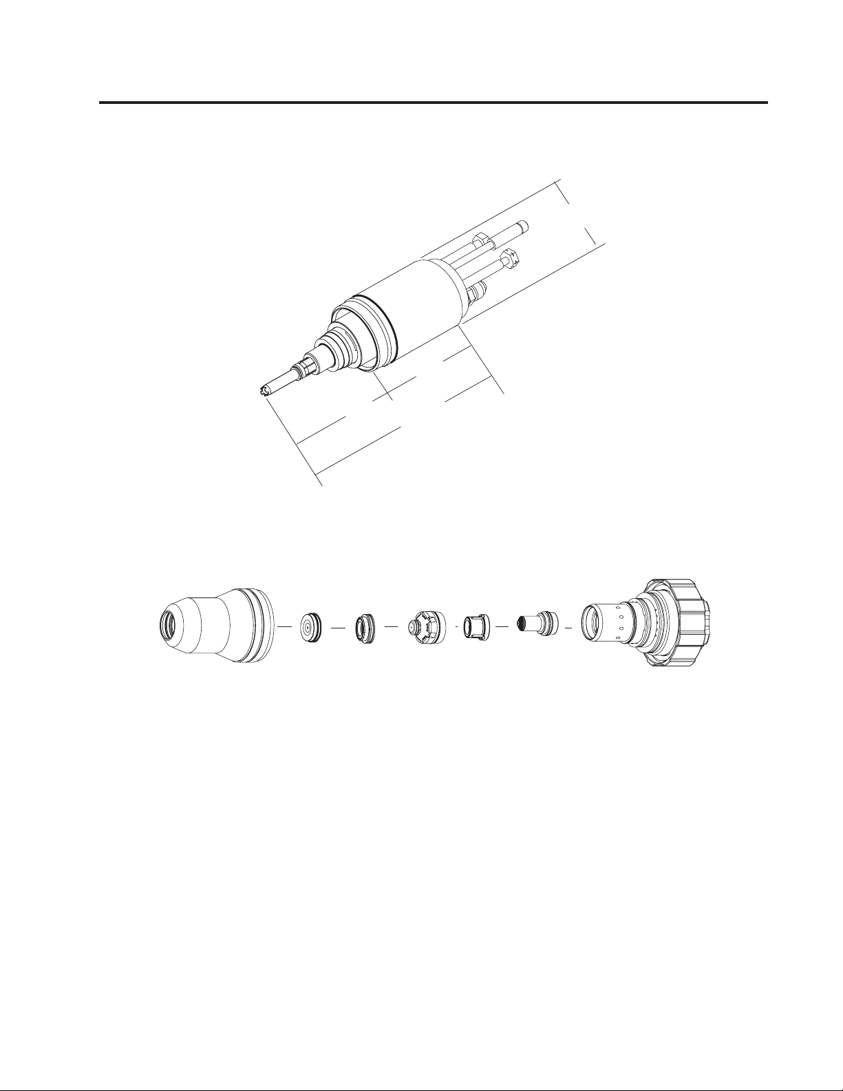
A. Torch Dimensions
Section 2: Torch Specifications
2" Diameter
3.25"
2.75"
6.00"
Art # A-04699
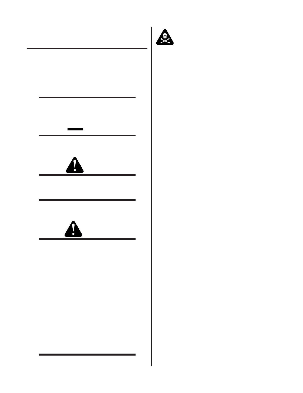
B. Torch Parts (Generic Parts Shown)
Art # A-04741
Shield Gas
Distributor
Shield Cap
Shield Cup
Tip
Plasma Gas
Distributor
Electrode
Cartridge
C. Parts - In - Place (PIP)
The torch is designed for use with a power supply which senses coolant return flow to confirm that torch
parts are in place. If coolant return flow to the power supply is absent or insufficient the power supply will
not provide power to the torch. Coolant leakage from the torch also indicates that torch parts are absent
or installed improperly.
D. Type of Cooling
Combination of gas stream through torch and liquid cooling.
Manual No. 0-2912 2-1 SPECIFICATIONS
Page 12

E. XTTM-300 Torch Data (with Hypertherm HD3070 Power Supply)
p
TM
XT
-300 Torch Ratings
for use with Hypertherm HD3070 Power Supply
Ambient
Temperature
Duty Cycle 100% @ 100 Amps
Maximum Current 100 Amps
Voltage (V
)500V
eak
Arc Striking Voltage 10kV
Current
Minimum Coolant
Flow Requirements
TM
XT
-300 Torch Gas Specifications
Plasma Gases:
Shield Gases:
Operating Pres sure
Maximum Input Pressure 135 psi / 9.3 bar
Gas flow 10 - 300 scfh
104° F
40° C
Up to 100 Amps, DC,
Straight Polarity
0.9 gpm (3.4 lpm)
Compressed Air, Oxygen,
Nitrogen, H35, F5
Compressed Air, Oxygen,
Nitrogen, Water
125 psi ± 10 psi
8.6 bar ± 0.7 bar
Manual No. 0-2912 2-2 SPECIFICATIONS
Page 13
SECTION 3:
INSTALLATION
3.01 Unpacking
The product is packaged and protected to prevent damage during shipping.
1. Unpack each item and remove all packing material.
2. Locate the packing list(s) and use the list to identify and account for each item.
3. Inspect each item for possible shipping damage. If damage is evident, contact your distributor and/or shipping
company before proceeding with system installation.
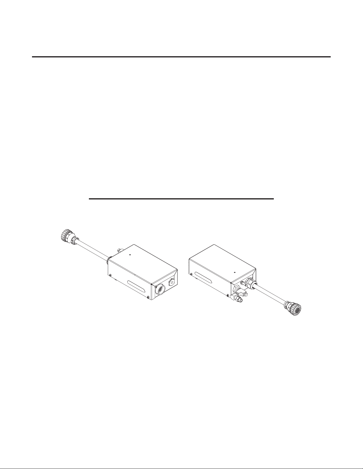
3.02 Oxygen Plasma Pre-Charge Unit Installation
The Oxygen Plasma Pre-Charge Unit is an addition to the Gas Control console on the HD-3070 Power Supply. The
pre-charge unit is used to increase the line pressure of the plasma gas (Oxygen) at the start of a cut cycle. The precharge unit is activated only during pre-flow when the gas selection switch is set to cut with Oxygen. This added
pressure provides improved consumable life during piercing. When cutting with any other plasma gas, the pre-charge
unit is not activated.
NOTE
The Thermal Dynamics Pre-Charge Unit is for use only with oxygen (O2)
gas.
Art # A-06722
Oxygen Plasma Pre-Charge Unit
A. Parts Supplied
The Pre-Charge Unit includes:
• Oxygen Plasma Pre-Charge Unit
• Oxygen Plasma Pre-Charge Supply Hose
• Oxygen Plasma Pre-Charge Outlet Hose
• Oxygen Plasma Outlet Tee Assembly
• Flashback Arrestor
Manual 0-2912 3-1 INSTALLATION
Page 14

B. Connecting Oxygen Plasma Pre-Charge Unit
Refer to the connection diagrams and install the Pre-Charge Unit as follows:
1. Place the Unit on top of the existing Gas Console.
2. Disconnect the 3x1 Cable coming from the Plasma Power Supply from the existing Gas Console.
3. Connect the 3x1 Cable to the mating connector on the Oxygen Plasma Pre-Charge Unit.
4. Connect the end of the new 3x1 Cable supplied on the Pre-Charge Unit to the mating connector on the
existing Gas Console.
5. Disconnect the plasma gas line (blue) that goes to the torch from the existing Gas Console.
CAUTION
Do not use PTFE sealant with components carrying oxygen (O2). Do
not overtighten fittings or hose connections.
6. Install the Plasma Outlet Tee Assembly on the existing Gas Console. Angle the Plasma Outlet Tee Assembly
towards the Oxygen Plasma Pre-Charge Unit.
7. Connect the existing plasma gas line (blue) from the torch to the Plasma Outlet Tee Assembly.
8. Refer to the illustrations captioned 'after Pre-Charge Unit Installation'. Install the flash-back arrestor on the
pre-charge unit.
9. Connect the supplied hose between the flash-back arrestor and the Plasma Outlet Tee Assembly.
10.Connect the fitting on the hose from the Pre-Charge Unit to the O2A-1/8 NPT Straight Adapter on the Plasma
Outlet Tee Assembly.
11.Disconnect the oxygen (O2) supply line from the Gas Console.
12. Remove the existing oxygen (O2) supply line fitting from the Gas Console.
13. Connect the supplied Plasma Pre-Charge Supply Hose between the O2B fitting on the Oxygen Plasma PreCharge Unit tee and the existing Gas Console oxygen (O2) supply connection.
14. Remove the plug from the Tee Fitting of the Pre-Charge Unit.
CAUTION
Test all connections for leaks. Tighten connections as needed. Do not
overtighten.
15.Connect the oxygen (O2) supply line to the Oxygen Plasma Pre-Charge Unit tee.
16. Attach the ground wire from the ground stud on the Oxygen Plasma Pre-Charge Unit to the ground stud on
the Gas Console.
INSTALLATION 3-2 Manual 0-2912
Page 15
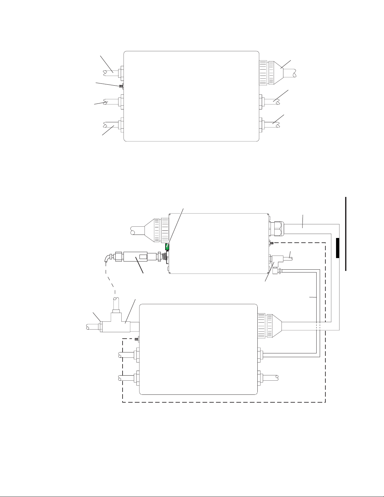
Plasma Gas Line
To Torch
Ground Stud
Connection
Shield Gas Line
To Torch
Pre-Flow Gas Line
To Torch
Manual Gas Console
A-03785
Connection Diagram Of Original Manual Gas Console
3X1 Cable From
Power Supply
O2 Supply Line
N2 Supply Line
3X1 Cable From Power Supply
Original Plasma
Gas Line Fitting
Plasma Gas Line
To Torch
Shield Gas Line To Torch
Pre-Flow Gas Line To Torch
Green Light (Refer to Operation
Section of Torch Manual)
Flashback Arrestor
Plasma Outlet Tee Assembly
Manual Gas Console
Pre-Charge
Unit
Connect To Mating Connector
On Gas Console
O2 Supply Line
Tee Fitting
O2 Supply Hose
To Gas Console
N2 Supply Line
CAUTION
Do not interchange parts. Make sure the parts in the torch corre-
spond with the plasma and shield gas in use for the application.
Art # A-04449
Ground Stud Connection
Connection Diagram to Manual Gas Console After Pre-Charge Unit Installation
Manual 0-2912 3-3 INSTALLATION
Page 16
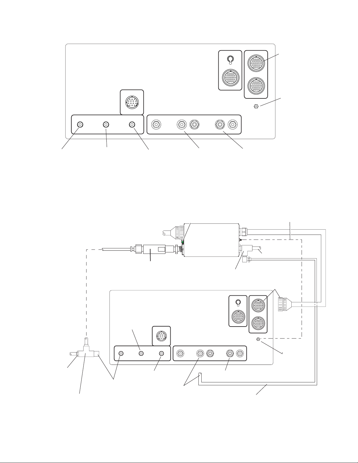
Automated Gas Console
3X1 Cable From
Power Supply
Ground Stud
Connection
Art # A-03948
Plasma Gas Line
To Torch
Shield Gas Line
To Torch
Pre-Flow Gas Line
To Torch
O2 Supply Line
Connection Diagram for Original Automated Gas Console
Green Light (Refer to Operation
Section of Torch Manual)
3X1 Cable From Power Supply
Flashback Arrestor
Pre-Charge
Unit
Tee Fitting
Automated Gas Console
Shield Gas Line
To Torch
N2 Supply Line
Ground Stud Connection
O2 Supply Line
Connect To 3x1
Connector On
Gas Console
Plasma Gas Line
To Torch
Original Plasma
Gas Line Fitting
Plasma Outlet
Tee Assembly
Pre-Flow Gas Line
Connect to Plasma
Gas Line Fitting
To Torch
Connect to O
Supply Line Fitting
2
N2 Supply Line
O2 Supply Hose
To Gas Console
Connect to
Stud Connection
Art # A-04450
Connection Diagram for Automated Gas Console after pre-Charge Unit Installation.
INSTALLATION 3-4 Manual 0-2912
Page 17
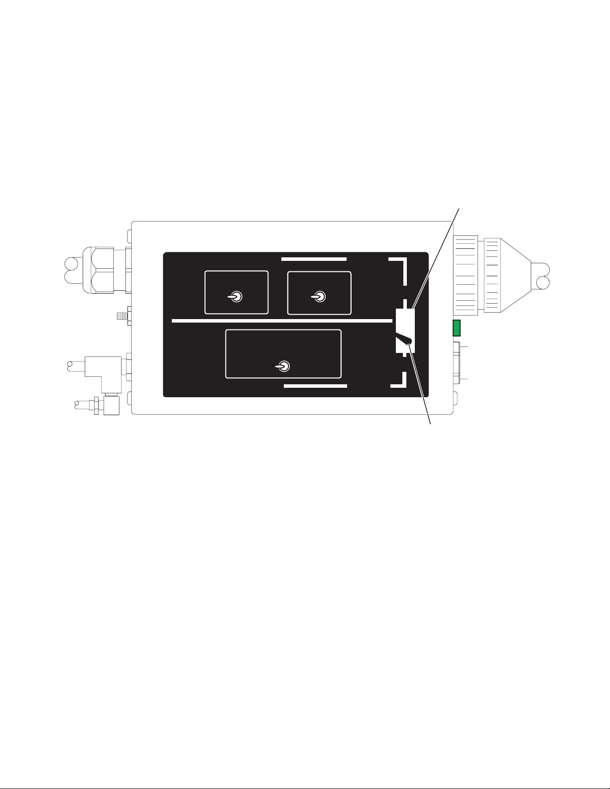
3.03 Oxygen Plasma Pre-Charge Unit Switch Setting
1. Turn the Oxygen Plasma Pre-Charge Unit upside down. The bottom of the assembly includes a label and a
cut-out. There is a toggle switch inside the cut-out.
2. Compare the label on the bottom of the Oxygen Plasma Pre-Charge Unit to the switches on the Gas Console.
For installations with Gas Consoles with switches as shown on the lower half of the label, set the toggle switch
on the Oxygen Plasma Pre-Charge Unit to position 'A'. For installations with Gas Consoles with switches as
shown on the upper half of the label, set the toggle switch on the Pre-Charge Unit to position 'B'. Use a pencil
or similar tool to set the switch. Do not open the Oxygen Plasma Pre-Charge Unit.
Cut-out
Art # A-04447
AUTO GAS BOX VERSION
PLASMA
AUX
2 N2
O
ALL MANUAL GAS BOXES
AUTO GAS BOX VERSION
A
PLASMA GAS SELECTOR
O
2 H35&N2
SHIELD
AIR
AUX
B
INCLUDES
B
A
INCLUDES
Toggle Switch (in 'A' Position)
View of Bottom of Pre-Charge Unit
3. Turn the Oxygen Plasma Pre-Charge Unit right side up. Set the unit securely on the Gas Control.
4. Turn on the oxygen (O2) gas supply and check all connections for leaks.
5. This completes the installation of the Oxygen Plasma Pre-Charge Unit.
Manual 0-2912 3-5 INSTALLATION
Page 18
3.04 Connecting Torch
WARNINGS
Disconnect primary power at the source before disassembling the torch
or torch leads.
Use caution when removing the Pilot Return Lead from the existing Torch
as damage to the connection can result.
The Torch Head is a direct replacement for the Hypertherm Torch Head on the HD3070 System. Connect the Torch
Leads as follows:
1. Remove and set aside any consumables installed in the original torch. Release the torch positioning tube
from its support. Do not rotate the torch head or leads. Support the Torch Head and positioning tube manually.
2. Rotate the positioning tube to disconnect the Hypertherm Torch Head from the tube. Slide the tube back on
the leads to expose the torch leads connections to the torch head.
3. Disconnect the torch head from the leads. Set the torch head aside.
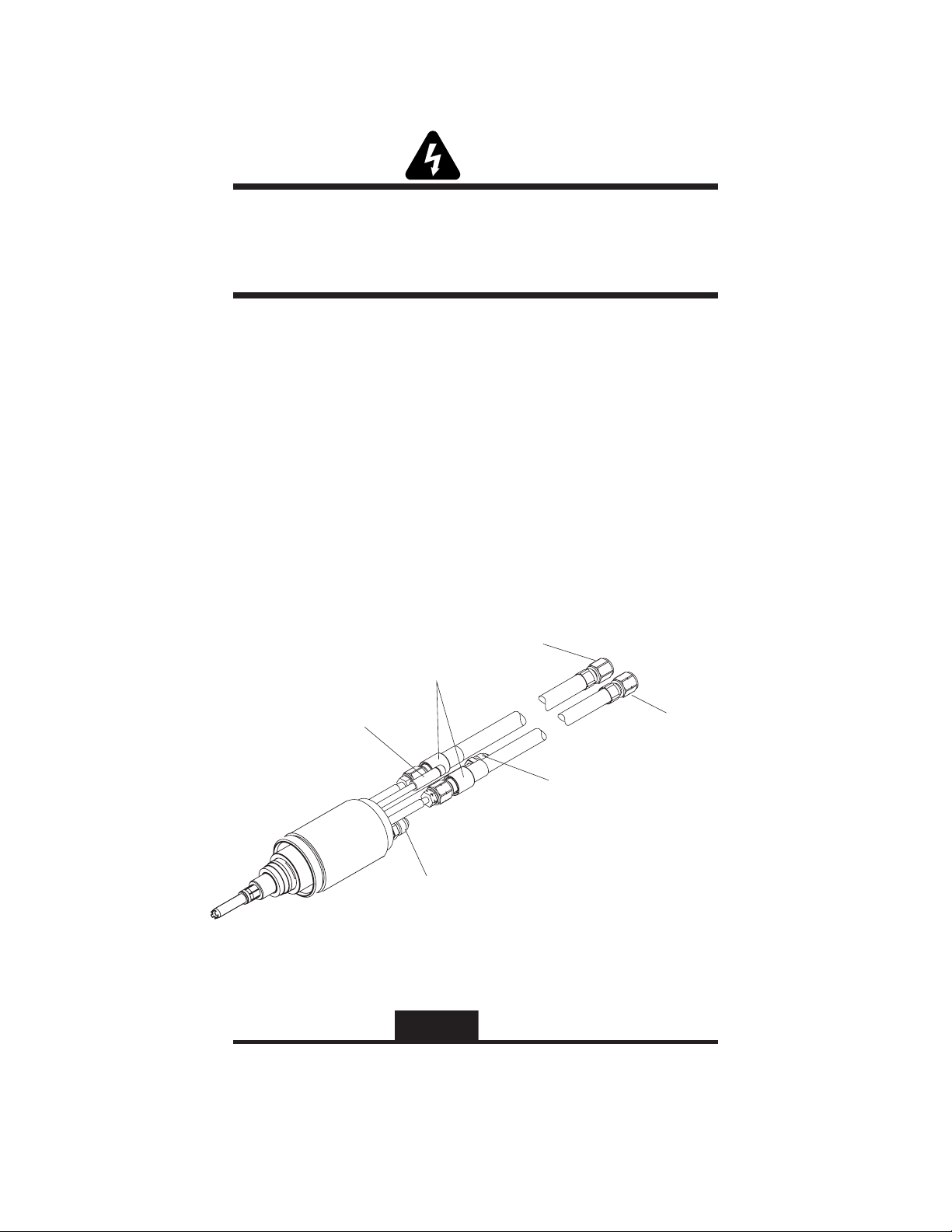
4. Connect the gas and coolant leads to the Torch Head.
a. Coolant supply and return connections to the Torch Head are of different lengths.
b. Plasma and secondary gas connections to the Torch Head are threaded differently; the plasma gas con-
nection is left-hand thread, the shield gas connection is right-hand thread.
Shield Gas
Heat Shrink
Pilot Lead (+)
Coolant Supply
Power Lead (-)
Coolant Return
Plasma Gas
(Left Hand Thread)
&
Art # A-04518
c. Hold the Torch Head leads connectors stationary; turn the leads fittings with a wrench to secure the leads
to the Torch Head. Do not overtighten.
CAUTION
The gas and coolant leads include compression fittings. Do not use sealant on these connections.
Slowly apply pressure to the gas lines. Check for leaks at all connections
before continuing. If there are no leaks, shut off the gas supplies and
continue with installation.
INSTALLATION 3-6 Manual 0-2912
Page 19

5. Connect the pilot lead to the Torch Head. Press the two ends of the connector firmly together. Thread the
plastic lead cover/connector onto the mating Torch Head connector.
6. Press the Torch Head Assembly upward to connect to the Mounting Tube. Pull the leads back as needed to
ensure a proper fit to the Mounting Tube. Hold the Torch Head Assembly stationary; rotate the Mounting Tube
to thread it onto the Torch Head.
CAUTION
Ensure that the leads do not twist within the mounting tube. Leads must
lie as shown in the installation sketch.
Manual 0-2912 3-7 INSTALLATION
Page 20
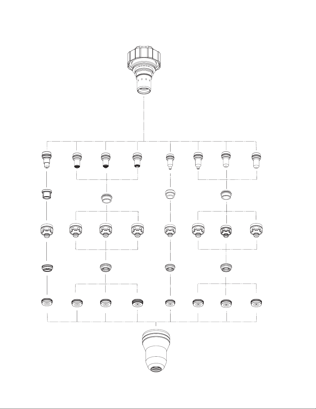
3.05 Consumables Selection
21-1020
Cartridge
Art # A-04031
30A Mild Steel, Precision
Electrode, 30A MS
Plasma
Tip, 30A MS
Shield
50A Mild Steel, Precision
21-1068
30A MS
21-1040
Gas Distributor,
21-1050
30A MS
21-1082
Gas Distributor,
21-1069
Electrode, 50A MS
21-1051
Tip, 50A MS
70A Mild Steel, Precision
21-1070
Electrode, 70A MS
Plasma
Gas Distributor
21-1052
Tip, 70A MS
Shield
Gas Distributor
100A Mild Steel, Precision
Electrode, 100A MS
21-1041
Tip, 100A MS
Swirl
21-1272
21-1071
21-1053
30A Stainless Steel, Precision
Electrode, 30A SS
Plasma
Tip, 30A SS
Shield
50A Stainless Steel / Aluminum, Precision
21-1077
Electrode, 50A SS/AL
21-1045
Gas Distributor
21-1059
No Swirl
Gas Distributor
Tip, 50A SS/AL
21-1274
70A Stainless Steel , Precision
21-1078
21-1060
100A Stainless Steel / Aluminum, Precision
21-1079
Electrode, 70A SS
Plasma
21-1041
Gas Distributor
21-1061
Tip, 70A SS
Shield
No Swirl
Gas Distributor
Electrode, 100A SS/AL
Tip, 100A SS/AL
21-1274
21-1080
21-1062
21-1024
Shield Cap, 30A MS
21-1025
Shield Cap, 50A MS
21-1026
Shield Cap, 70A MS
21-1027
Shield Cap, 100A MS
21-1033
Shield Cap, 30A SS
21-1016
Shield Cup
21-1034
Shield Cap, 50A SS/AL
21-1035
Shield Cap, 70A SS
21-1036
Shield Cap, 100A SS/AL
INSTALLATION 3-8 Manual 0-2912
Page 21
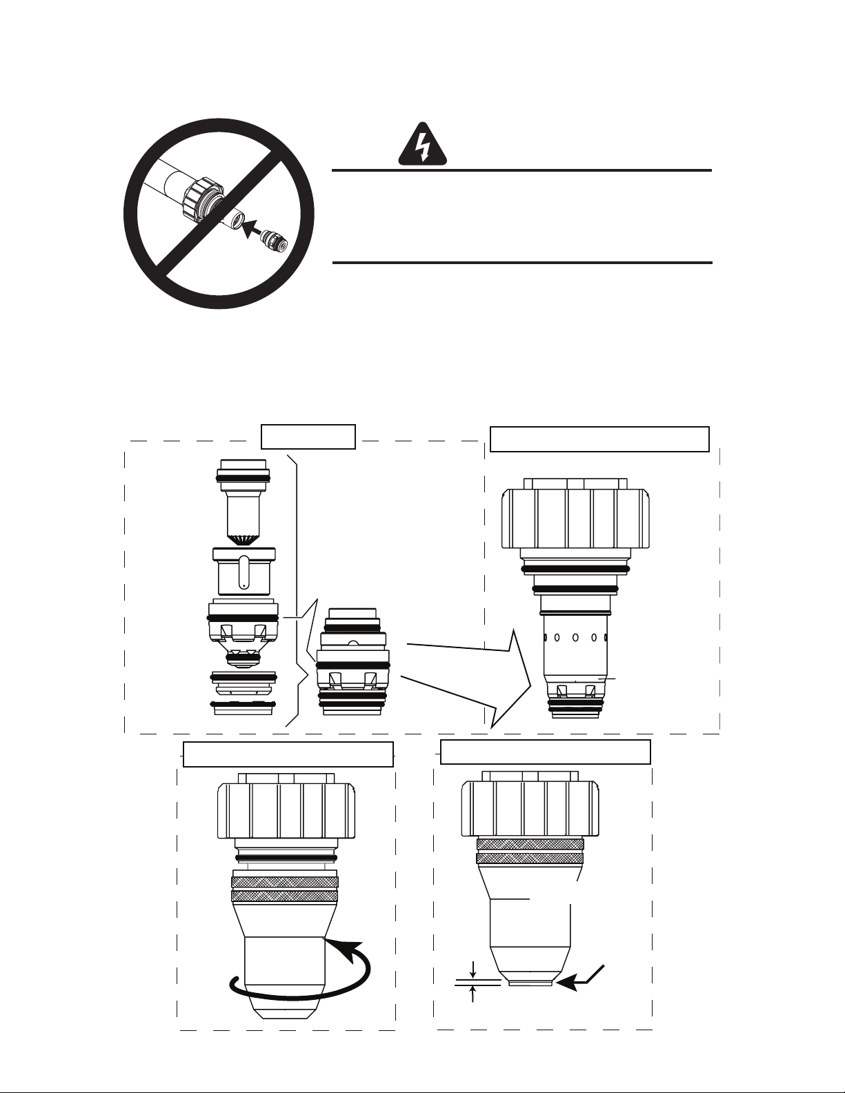
Install Consumable Torch Parts
WARNINGS
Do not install consumables into the Cartridge
while the Cartridge is attached to the Torch Head.
Keep foreign materials out of the consumables and Cartridge.
Handle all parts carefully to avoid damage,
which may affect torch performance.
Art # A-03887
1. Check the appropriate cut chart for the right combination of parts for the cutting application.
2. Install the consumable parts as follows to ensure proper operation. These steps will help ensure that parts are
seated correctly.
Electrode
Plasma Gas
Distributor
Tip
Shield Gas
Distributor
Shield Cap
3: Thread Shield Cup onto Cartridge
1: Stack Parts
Upper O-Ring
on Tip
2: Press Cartridge onto Stacked Parts
No Gaps
Between Parts
Cartridge Covers
Upper O-Ring
on Torch Tip
4: Check Shield Cap Protrusion
Shield Cup
Shield Cap
Shield Cap Protrudes
0.063-0.083" (1.6 - 2.1 mm)
Art # A-04716
Manual 0-2912 3-9 INSTALLATION
Page 22

3. Use the removal tool to hold the cartridge assembly, while turning the shield cup onto the cartridge
assembly. When this group is fully assembled, the shield should protrude from the front of the shield cup
0.063" to 0.083" (1.6 - 2.1 mm). Without this protrusion the shield cup is not properly tightened onto the
cartridge assembly.
4. Take the removal tool off the cartridge. Fit the cartridge assembly onto the torch head. The cartridge should
seal to the large O-ring on the torch body as shown. If the cartridge does not seal on the O-ring, the cartridge
is not fully tightened.
CAUTION
Do not force the cartridge if it will not fully tighten. Remove the cartridge
and gently clean the threads on the torch head body with a wire brush.
Apply oxygen-compatible lubricant (supplied with the torch) to the threads.
Torch Head
0.063 - 0.083"
(1.6 - 2.1 mm)
Protrusion
Installing Assembled Cartridge Onto Torch Head
5. Slide the ohmic clip over the shield cup if using ohmic torch height sensing.
Torch Head O-Ring
Art # A-07202
Ohmic Clip
A-03393
6. Connect the wire lead from the height finder to the ohmic clip if using ohmic torch height sensing.
7. Connect the wire lead from the height finder to the ohmic clip.
INSTALLATION 3-10 Manual 0-2912
Page 23

3.06 Oxygen Plasma Pre-Charge Unit Installation Checks
ALWAYS verify proper function of the plasma pre-charge unit. Follow the steps below to verify the unit is installed
properly.
The pre-charge unit is used to increase the line pressure of the plasma gas (Oxygen) at the start of a cut cycle. The
pre-charge unit is activated only during pre-flow when the gas selection switch is set to cut with Oxygen. This added
pressure provides improved consumable life during piercing. When cutting with any other plasma gas, the pre-charge
unit is not activated.
To verify that the Oxygen Plasma Pre-Charge Unit is installed properly, check it as follows:
1. Be sure that O2 is being supplied to the pre-charge unit and to the gas box.
2. Be sure the gas outlet of the plasma pre-charge box is teed into the plasma lead.
3. Check the switch on the bottom of the pre-charge box to see if it is in the proper position (switch is changed
according to the type of gas box used.
4. Set the gas selection switch on the gas box to “O2/N2” cutting.
5. Turn on “Test Cut Flow” and observe the plasma outlet pressure of the gas box. This pressure will vary with
the consumables in the torch, but should generally be less than 60 psi. This is called the
pressure
6. Now turn the switch to “Test Pre-Flow”, and observe the outlet pressure of the plasma gas. It should climb to
120 PSI and the Green Light should be illuminated. This indicates that the plasma line (Oxygen) is correctly
being “pre-charged” to 120 PSI during pre-flow.
.
plasma cold flow
7. Now turn the switch back to “Test Cut-Flow”, and observe the outlet pressure of the plasma gas. It should drop
down to the plasma cold flow pressure.
Now verify that the plasma pre-charge unit is not energizing under the following conditions:
1. Set the Plasma Gas Selection switch off of Oxygen cutting (to H35 or Aux).
2. Turn on “Test Cut Flow” and observe the
3. Now turn the switch to “Test Pre-Flow”, and observe the outlet pressure of the plasma gas. It should remain at
the plasma cold flow pressure and the Green light should not be illuminated. This indicates that the plasma
pre-charge unit is not activating.
plasma cold flow pressure
.
Manual 0-2912 3-11 INSTALLATION
Page 24
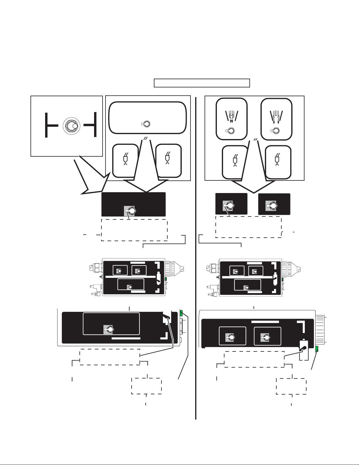
3.07 Oxygen Plasma Pre-Charge Unit Operational Check
THE PRE-CHARGE UNIT INCLUDES A GREEN LIGHT TO INDICATE THAT THE SYSTEM IS PRE-CHARGING
THE TORCH LEADS WITH OXYGEN. Follow the steps shown to confirm that switches on the gas console and on
the pre-charge unit are set properly. DO NOT OPERATE the system unless all gas control switches are set properly.
Compare to Gas Control Console Switches
HD3070 3-KNOB MANUAL BOX
PLASMA
(AUX A)
HD3070 6-KNOB AUTO BOX SWITCH SETTINGS
O
PLASMA GAS SELECTION
2
AIR
O
2
H35 & N2
HD3070 5-KNOB AUTO BOX SWITCH SETTINGS
PLASMA
O
2
AUX
A
SHIELD
N2
AUX
B
(AUX B)
Change Switch
to O2 position.
SHIELD
N
2
TEST
RUN
PREFLOW
PLASMA GAS SELECTION
AIR
2
H35&N
O
In Version A installations:
Is the Plasma Gas Selector switch
No
in the O2 position?
Check underside of Plasma Pre-Charge Unit
AUTO GAS BOX VERSION
PLASMA
AUX
O
2
PLASMA GAS SELECTOR
O
ALL MANUAL GAS BOXES
AUTO GAS BOX VERSION
A
2
H35&N
INCLUDES
SHIELD
AUX
N2
B
AIR
2
INCLUDES
Underside of Pre-Charge Unit
TEST
CUTFLOW
2
B
A
Version A
Yes
TEST
PREFLOW
(4, 5)
RUN
TEST
CUTFLOW
(1, 2, 3)
Version B
PLASMA
O
2
AUX
A
SHIELD
N2
AUX
B
In Version B installations:
Is the Plasma Gas Selector switch
Yes
in the O2 position?
No
Check underside of Plasma Pre-Charge Unit
AUTO GAS BOX VERSION
PLASMA
AUX
O
2
PLASMA GAS SELECTOR
O
ALL MANUAL GAS BOXES
AUTO GAS BOX VERSION
A
2
H35&N
INCLUDES
SHIELD
N2
AIR
B
AUX
B
A
2
INCLUDES
Underside of Pre-Charge Unit
Change Switch
to O2 position.
PLASMA GAS SELECTION
Change Switch
Art # A-06409
ALL MANUAL GAS BOXES
AUTO GAS BOX VERSION
Is the Pre-Charge Unit switch
No
to A position.
AIR
O
2
H35&N
in the A position?
2
INCLUDES
Yes
Is the green
light ON?
Yes
All switches are
set properly.
A
Green Light
AUTO GAS BOX VERSION
PLASMA
AUX
O
2
Is the Pre-Charge Unit switch
No
Change Switch
to B position.
SHIELD
N2
A
in the B position?
INCLUDES
AUX
B
Yes
Is the green
light ON?
Yes
All switches are
set properly.
B
Green Light
INSTALLATION 3-12 Manual 0-2912
Page 25

SECTION 4-A:
OPERATION WITH MANUAL GAS CONSOLE
4A.01 Torch Parts Selection
The application will determine which torch parts must be used. Refer to the speed charts in Section 4.02, Recommended Cutting Speeds, for the proper torch parts to install for a selected application.
CAUTION
Do not interchange parts. Make sure all parts in the torch correspond with the plasma and shield gas in use for the
application.
4A.02 Pre-Setting Controls
A. Power Supply Setting
Set the Power Supply controls as follows before operating the system.
1. Set the proper cutting current at the AMPS thumbwheel.
2. Use data from the Speed Charts in Section 4.03 for each combination of material and amperage:
a. Set the initial torch height.
b. Set arc voltage on the torch height control.
c. Set the PIERCE DELAY potentiometer.
3. On the gas console select the plasma gas to be used with the PROCESS SELECTION switch.
4. All gas supplies are connected and set at 120 psi (8.3 bar) at the inlet pressure gauges.
B. Pre-Charge Box Setting
Before operating the system:
1. Set the gas supply pressure at the oxygen cylinder to 120 psi (8.3 bar).
2. On the front of the gas console set the RUN TEST switch to the TEST PREFLOW position. This will enable
gas to flow by opening the solenoid in the Pre-Charge Box.
3. If system plasma pressure gauge indicates more than 120 psi (8.3 bar) the system is over pressurized. Stop
and do the following:
a. On the front of the gas console set the RUN TEST switch to the TEST CUT FLOW position.
b. Let gas flow for 20 seconds. This will allow the system pressure to bleed off.
c. Repeat steps 2 and 3 above.
Manual 0-2912 4A-1 Operation with Manual Gas Control
Page 26

4A.03 Recommended Cutting Speeds
!
Cutting speed depends on material and thickness. The following factors may affect system performance:
• Torch parts wear
• Speed
• Gas quality
• Operator experience
• Torch standoff height
• Proper work cable connection
• Alloy content of material
NOTE
This information represents realistic expectations using recommended practices and well-maintained systems. Actual speeds may vary from those shown in the charts depending on the alloy content of the selected material.
For complete cutting speed chart data refer to the following pages.
WARNING
Information in this section is for torch operation with the HD3070 System with a manual gas console.
Refer to Section 3B or 3C for information on torch operation with the HD3070 System with an automatic gas console.
Art # A-04492
Art # A-04491
Preflow Controls
Shield Controls
Plasma Control
Plasma Controls
Preflow Controls
Shield Controls
Operation with Manual Gas Control 4A-2 Manual 0-2912
Page 27

OPERATING INFORMATION
** - Arc voltage is based on 50 ft (15.2 m) torch lead length. For other lead lengths the operator may need to adjust
the Arc Voltage setting. Refer to Appendix 1 for Alternate Arc Voltage Settings.
NOTE: The preflow rates shown generate increased dross at the start of a cut. Increasing the amount of oxygen and
reducing the amount of nitrogen will reduce dross at the start of a cut, but will also reduce electrode life.
Oxygen (O2) gas inlet pressures must be 120 psi (8.3 bar) for all material thicknesses.
Slightly increasing the preflow flow rates may increase piercing capability on the thicker materials listed above.
However, increasing the preflow flow rates too much may affect plasma starting reliability (misfiring).
Torch Working Height tolerances are ±0.005 inch (±0.125 mm).
Thermal Dynamics Pre-Charge Unit must be installed before cutting.
ChartS give set-up parameters for use with a Hypertherm HD 3070 System. For technical and legal reasons the
settings in the chartS may not be appropriate for use with other systems.
Manual 0-2912 4A-3 Operation with Manual Gas Control
Page 28

Mild Steel
30A
O
Plasma / O2 - N2 Shield
2
Manual
Gas Control
Or
Art # A-06838
Shield Cup
21-1016
Material
Thickness
(ga) (in)
Shield
Shield Cap
21-1024
Cut Flow Rates (%)
Gas Distributor
21-1082
Preflow Flow
Tip
21-1050
Rates
Plasma (%) Shield (%) Preflow (%)
O
2
-O2N2 O
N2
2
Plasma
Gas Distributor
21-1040
Tor c h
** Arc
Voltage
Working
Height
(volts )
(in)
Electrode
21-1068
Travel
Speed
(ipm)
Cartridge
21-1020
Initial
Piercing
Height
(in)
Art # A-04338
Pierce
Delay
(sec )
20 0.036 13 - 13 0 5 55 129 0.050 140 0.120 0.2
16 0.060 13 - 13 0 5 55 137 0.050 80 0.120 0.2
14 0.075 13 - 13 0 5 55 139 0.070 50 0.120 0.2
11 0.120 13 - 17 3 5 55 140 0.070 40 0.120 0.2
10 0.135 13 - 17 3 5 55 142 0.070 35 0.120 0.2
9 0.150 13 - 17 3 5 55 143 0.070 33 0.120 0.3
7 0.179 13 - 17 3 5 55 144 0.070 30 0.120 0.3
Preflow Flow
Rates
Tor c h
** Arc
Voltage
N2
2
(volts )
Working
Height
(mm)
Travel
Speed
(m/min)
indicates maximum piercing parameters.
Initial
Piercing
Height
(mm)
Pierce
Delay
(sec )
Material
Thickness
(mm)
0.6
0.8
1
1.2
1.5
2
3
4
5
Cut Flow Rates (%)
Plasma (%) Shield (%) Preflow (%)
O
2
-O2N2 O
13 - 13 0 5 55 125 1.3 4.8 3.0 0.1
13 - 13 0 5 55 125 1.3 4.1 3.0 0.1
13 - 13 0 5 55 129 1.3 3.6 3.0 0.1
13 - 13 0 5 55 129 1.3 2.9 3.0 0.1
13 - 13 0 5 55 136 1.3 2.2 3.0 0.2
13 - 13 0 5 55 139 1.8 1.3 3.0 0.2
13 - 17 3 5 55 140 1.8 1.1 3.0 0.2
13 - 17 3 5 55 142 1.8 0.9 3.0 0.2
13 - 17 3 5 55 145 1.8 0.7 3.0 0.3
Bold type
Operation with Manual Gas Control 4A-4 Manual 0-2912
Page 29

Mild Steel
50A
O
Plasma / O2 - N2 Shield
2
Manual
Gas Control
Or
Art # A-06838
Shield Cup
21-1016
Material
Thickness
(ga) (in)
Shield
Shield Cap
21-1025
Gas Distributor
Cut Flow Rates (%)
21-1272
Tip
21-1051
Preflow Flow
Rates
Plasma % Shield % Preflow %
O
2
- O
2
N2 O
N2
2
Plasma
Gas Distributor
21-1041
Tor c h
** Arc
Voltage
Working
Height
(volts )
(in)
Electrode
21-1069
Travel
Speed
(ipm)
Cartridge
21-1020
Initial
Piercing
Height
(in)
Art # A-04026
Pierce
Delay
(sec )
20 0.036 20 - 5 25 10 40 122 0.060 500 0.100 0.3 *
16 0.060 20 - 5 25 10 40 126 0.060 300 0.100 0.3 *
10 0.135 20 - 5 25 10 40 130 0.060 150 0.200 0.1
7 0.179 20 - 5 25 5 65 134 0.080 100 0.200 0.1
1/4 20 - 5 25 5 65 135 0.080 80 0.200 0.1
3/8 20 - 5 15 5 65 148 0.110 25 0.350 0.3
Material
Thickness
(mm)
0.8
1.0
1.2
1.5
2.0
3.0
4.0
5.0
6.0
8.0
10.0
Bold type
Cut Flow Rates (%)
Plasma % Shield % Preflow %
2
- O
O
2
N2 O
20 - 5 25 10 40 122 1.5 12.7 2.5 0.3 *
20 - 5 25 10 40 123 1.5 12.0 2.5 0.3 *
20 - 5 25 10 40 124 1.5 9. 5 2.5 0.3 *
20 - 5 25 10 40 126 1.5 7. 6 2.5 0.3 *
20 - 5 25 10 40 127 1.5 6. 5 3.3 0.2 *
20 - 5 25 10 40 130 1.5 3. 8 4.8 0.1
20 - 5 25 10 40 132 2.0 3. 1 5.0 0.1
20 - 5 25 5 65 134 2.0 2.5 5.1 0.1
20 - 5 25 5 65 135 2.0 2.1 5.1 0.1
20 - 5 15 5 65 146 2.5 0.8 6.4 0.2
20 - 5 15 5 65 148 2.8 0.6 8.9 0.3
indicates maximum piercing parameters.
Preflow Flow
Rates
N2
2
** Arc
Voltage
(volts )
Tor c h
Working
Height
(mm)
Travel
Speed
(m/min)
Initial
Piercing
Height
(mm)
Pierce
Delay
(sec )
Manual 0-2912 4A-5 Operation with Manual Gas Control
Page 30

Mild Steel
70A
O
Plasma / O2 - N2 Shield
2
Manual
Gas Control
Or
Art # A-06838
Shield Cup
21-1016
Material
Thickness
(ga) (in)
Shield
Shield Cap
21-1026
Gas Distributor
21-1272
Cut Flow Rates (%)
Tip
21-1052
Preflow Flow
Rates (% )
Gas Distributor
Plasma % Shield % Preflow %
O2 - O2N2O2N2
Plasma
21-1041
** Arc
Voltage
(volts )
21-1070
Tor c h
Working
Height
(in)
Travel
Speed
(ipm)
Cartridge
21-1020Electrode
Art # A-04027
Initial
Piercing
Height
(in)
Pierce
Delay
(sec )
16 0.060 25 - 25 0 5 65 138 0.060 300 0.100 0.0
14 0.075 25 - 25 0 5 65 138 0.060 250 0.100 0.0
12 0.105 65 - 10 45 5 65 140 0.060 225 0.120 0.0
10 0.135 65 - 10 45 5 65 142 0.060 200 0.150 0.0
7 0.179 65 - 10 45 5 65 143 0.070 120 0.200 0.1
- 1/4 65 - 10 45 5 65 146 0.080 110 0.200 0.2
- 3/8 65 - 10 45 5 65 150 0.120 70 0.300 0.2
Preflow Flow
Rates (% )
** Arc
Voltage
(volts )
Tor c h
Working
Height
(mm)
Travel
Speed
(m/min)
Initial
Piercing
Height
(mm)
Material
Thickness
(mm)
1.5
2
3
4
5
6
8
Bold type
Cut Flow Rates (%)
Plasma % Shield % Preflow %
O2 - O2 N2 O2 N2
25 - 25 0 5 65 138 1.5 7.6 2.5 0.0
25 - 25 0 5 65 138 1.5 6.8 2.5 0.0
65 - 10 45 5 65 141 1.5 5.3 3.7 0.0
65 - 10 45 5 65 141 1.5 4.1 3.7 0.0
65 - 10 45 5 65 144 1.9 3.0 5.2 0.0
65 - 10 45 5 65 146 1.9 2.5 5.2 0.0
65 - 10 45 5 65 148 2.5 2.3 6.4 0.1
indicates maximum piercing parameters.
Pierce
Delay
(sec )
Operation with Manual Gas Control 4A-6 Manual 0-2912
Page 31

Mild Steel
100A
O
Plasma / O2 - N2 Shield
2
Manual
Gas Control
Or
Art # A-06838
Shield Cup
21-1016
Material
Thickness
(ga) (in)
Cut Flow Rates (%)
Plasma % Shield % Preflow %
O
2
10 0.135 62
7 0.179 62
-1/462
-3/862
-1/262
-5/862
Shield Cap
21-1027
Shield
Gas Distributor
21-1272
Tip
21-1053
Plasma
Gas Distributor
21-1041
Electrode
21-1071
Preflow Flow
Rates (%)
Tor c h
** Arc
-O2N2 O
- 15 70 15 80 141 0.070 280 0.200 0.0
- 15 70 15 80 145 0.090 235 0.200 0.0
-
- 15 70 15 80 156 0.110 100 0.250 0.2
- 15 86 15 80 158 0.120 70 0.300 0.3
- 15 86 15 80 163 0.120 50 0.350 0.5
15 70 15 80 153 0.100 150 0.200 0.0
2
N2
Voltage
(volts )
Working
Height
(in)
Travel
Speed
(ipm)
Initial
Piercing
Height
(in)
Cartridge
21-1020
Art # A-04028
Pierce
Delay
(sec )
-3/462
Material
Thickness
Plasma % Shield % Preflow %
(mm)
O
3
4
5
6
8
10
12
15
20
Bold type
indicates maximum piercing parameters.
62
62
62
62
62
62
62 - 15 86 15 80 158 3.0 1.9 7.1 0.3
62 - 15 86 15 80 162 3.0 1.2 8.4 0.4
62 - 15 86 15 80 176 3.8 0.6 10.2 0. 4
-
15 86 15 80 176 0.150 25 0.400 0.6
Cut Flow Rates (%)
2
-O2N2 O
- 15 70 15 80 142 2.3 6.2 4.5 0.0
- 15 70 15 80 145 2.3 5.7 4.8 0.0
- 15 70 15 80 148 2.3 5.3 5.1 0.0
-
- 15 70 15 80 155 2.8 3.2 5.8 0.1
- 15 70 15 80 156 3.0 2.1 6.6 0.2
15 70 15 80 152 2.3 4.6 5.1 0.0
Preflow Flow
Rates (%)
N2
2
** Arc
Voltage
(volts )
Tor c h
Working
Height
(mm)
Travel
Speed
(m/min)
Initial
Piercing
Height
(mm)
Pierce
Delay
(sec )
Manual 0-2912 4A-7 Operation with Manual Gas Control
Page 32

Stainless Steel
30A
Air Plasma / Air Shield
Manual
Gas Control
Or
Art # A-06838
Shield Cup
21-1016
Material
Thickness
(ga) (in) Air - Air - Air -
Shield Cap
21-1033
Cut Flow Rates (%)
Plasma % Shield % Preflow %
Shield
Gas Distributor
21-1274
Tip
21-1059
Preflow Flow
Gas Distributor
Plasma
21-1045
** Arc
Voltage
(volts )
Tor c h
Working
Height
(in)
21-1077
Travel
Speed
(ipm)
Cartridge
21-1020Electrode
Initial
Piercing
Height
(in)
Art # A-04498
Pierce
Delay
(sec )
26 0.019 60 - 10 - 75 - 75 0.020 250 0.200 0.0
24 0.025 60 - 10 - 75 - 75 0.020 220 0.200 0.0
22 0.031 60 - 10 - 75 - 75 0.020 200 0.200 0.0
20 0.038 60 - 10 - 75 - 75 0.020 180 0.200 0.0
18 0.050 60 - 10 - 75 - 79 0.020 150 0.200 0.0
16 0.063 60 - 10 - 75 - 79 0.020 120 0.200 0.0
Material
Thickness
(mm)
0.6
0.8
1.0
1.2
1.5
2.0
Bold type
Cut Flow Rates (%)
Plasma % Shield % Preflow %
Air - Air - Air -
60 - 10 - 75 - 75 0.5 5.8 5.0 0.0
60 - 10 - 75 - 75 0.5 5.1 5.0 0.0
60 - 10 - 75 - 75 0.5 4.6 5.0 0.0
60 - 10 - 75 - 79 0.5 3.9 5.0 0.0
60 - 10 - 75 - 79 0.5 3.3 5.0 0.0
60 - 10 - 75 - 79 0.5 2.0 5.0 0.1
indicates maximum piercing parameters.
Preflow Flow
** Arc
Voltage
(volts )
Tor c h
Working
Height
(mm)
Travel
Speed
(m/min)
Initial
Piercing
Height
(mm)
Pierce
Delay
(sec )
Operation with Manual Gas Control 4A-8 Manual 0-2912
Page 33

Stainless Steel
50A
Air Plasma / Air Shield
Manual
Gas Control
Or
Art # A-06838
Shield Cup
21-1016
Material
Thickness
(ga) (in) Air - Air - Air -
Shield Cap
21-1034
Cut Flow Rates (%)
Plasma % Shield %
Shield
Gas Distributor
21-1274
Tip
21-1060
Preflow Flow
Preflow %
Gas Distributor
Plasma
21-1041
** Arc
Voltage
(volts )
21-1078
Tor c h
Working
Height
(in)
Travel
Speed
(ipm)
Cartridge
21-1020Electrode
Art # A-04029
Initial
Piercing
Height
(in)
14 0.075 65 - 80 - 65 - 113 0.060 120 0.120 0.0
12 0.105 65 - 80 - 65 - 117 0.060 80 0.150 0.0
10 0.135 65 - 80 - 65 - 121 0.060 55 0.180 0.1
- 3/16 65 - 80 - 65 - 123 0.080 40 0.250 0.3
Material
Thickness
(mm)
1.2
1.5
2
3
4
5
Bold type
Cut Flow Rates (%)
Plasma % Shield % Preflow %
Air - Air - Air -
65 80 - 65 -
65 80 - 65 -
65 80 - 65 -
65 80 - 65 -
65 80 - 65 -
65 80 - 65 -
indicates maximum piercing parameters.
Preflow Flow
** Arc
Voltage
(volts )
Tor c h
Working
Height
(mm)
Travel
Speed
(m/min)
Initial
Piercing
Height
(mm)
109 1.5 4.0 2.3 0.0
111 1.5 3.6 2.6 0.0
113 1.5 2.9 3.1 0.0
119 1.5 1.8 4.1 0.1
122 1.5 1.2 5.3 0.2
123 2.0 0.9 6.7 0.3
Pierce
Delay
(sec )
Pierce
Delay
(sec )
Manual 0-2912 4A-9 Operation with Manual Gas Control
Page 34

Stainless Steel
70A
Air Plasma / Air - CH
Shield
4
Manual
Gas Control
Or
Art # A-06838
Shield Cup
21-1016
Material
Thickness
(ga) (in) Air - Air CH
Shield Cap
21-1035
Cut Flow Rates (%)
Plasma (%) Shield (%) Preflow (%)
Shield
Gas Distributor
21-1274
Preflow Flow
Air C H
4
Tip
21-1061
Plasma
Gas Distributor
21-1041
** Arc
Voltage
(volts )
4
Electrode
Working
Height
(in)
21-1079
Travel
Speed
(ipm)
Cartridge
21-1020
Art # A-04341
Piercing
Height
(in)
Pierce
Delay
(sec )
10 0.135 35 - 60 30 75 0 141 0.080 100 0.140 0.3
-3/1635
-1/435
-3/835
-1/253
Material
Thickness
(mm)
1.5
Plasma (%) Shield (%) Preflow (%)
Ai r
35 - 20 10 75 0 140 2.0 3.2 3.0 0.2
- 60 20 75 0 151 0.080 60 0.140 0.4
-
- 20 10 75 0 154 0.140 40 0.200 0.5
-
Cut Flow Rates (%)
-
20 10 75 0 146 0.140 55 0.180 0.5
45 15 75 0 168 0.130 25 0.280 0.7
Air C H
Preflow Flow
Air C H
4
4
** Arc
Voltage
(volts )
Working
Height
(mm)
Travel
Speed
(m/min)
Piercing
Height
(mm)
Pierce
Delay
(sec )
2
3
4
5
6
8
10
12
Bold type
35
35
- 20 10 75 0 141 2.0 3.0 3.5 0.2
-
20 10 75 0 143 2.0 2.5 4.0 0.2
35 - 20 10 75 0 145 2.0 2.0 4.5 0.2
35 - 20 10 75 0 146 2.0 1.6 5.0 0.2
35 - 20 10 75 0 146 4.0 1.4 5.0 0.2
35 - 20 10 75 0 146 4.0 1.2 5.0 0.2
35 - 20 10 75 0 154 4.0 1.0 5.0 0.5
53 - 45 15 75 0 168 3.9 0.9 7.0 0.7
indicates maximum piercing parameters.
Operation with Manual Gas Control 4A-10 Manual 0-2912
Page 35

Stainless Steel
!
100A
Ar/H2 Plasma / N2 Shield
Manual
Gas Control
Art # A-06839
Shield Cup
21-1016
Material
Thickness
(ga)(in)H35N2N2N2N2N2
- 1/8 0 35 35 35 35 35 148 0.125 80 0.200 0.1
- 1/4 35 35 35 35 35 35 161 0.125 65 0.250 0.3
- 3/8 35 35 35 35 35 35 161 0.125 60 0.300 0.3
- 1/2 35 35 35 35 35 35 161 0.130 50 0.350 0.5
- 5/8 35 35 35 35 35 35 169 0.140 30 0.350 0.8
Material
Thickness
(mm)
3
Shield Cap
21-1036
Cut Flow Rates (%)
Plasma % Shield % Preflow %
Cut Flow Rates (%)
Plasma % Shield % Preflow %
H35N2N2N2N2N2
0 3535353535 148 3.2 2.0 5.1 0.1
Shield
Gas Distributor
21-1274
Plasma
Tip
21-1062
Preflow Flow ** Arc
Preflow Flow ** Arc
Gas Distributor
21-1041
Voltage
(volts )
Voltage
(volts )
Electrode
21-1080
Tor c h
Working
Height
Tor c h
Working
Height
Travel
Speed
(ipm)
Travel
Speed
(m/min)
Cartridge
21-1020
Art # A-04030
Initial
Piercing
Height
Initial
Piercing
Height
Pierce
Delay
(sec )
Pierce
Delay
(sec )
4
5
6
8
10
12
15
Bold type
indicates maximum piercing parameters.
35 35 35 35 35 35 155 3.2 1.9 6.0 0.3
35 35 35 35 35 35 161 3.2 1.8 6.4 0.3
35 35 35 35 35 35 161 3.2 1.7 6.4 0.3
35 35 35 35 35 35 161 3.2 1.6 6.4 0.3
35 35 35 35 35 35 161 3.2 1.5 7.6 0.4
35 35 35 35 35 35 161 3.3 1.3 8.9 0.5
35 35 35 35 35 35 167 3.6 0.9 8.9 0.7
CAUTION
Manual gas consoles with 3 flow meters cannot be used for 100A cutting with stainless steel.
Manual 0-2912 4A-11 Operation with Manual Gas Control
Page 36

Aluminum
50A
Air Plasma / Air Shield
Manual
Gas Control
Or
Art # A-06838
Shield Cup
21-1016
Material
Thickness
(ga) (in) - Air Air - Air -
14 0.075
12 0.105
10 0.135
-3/16
Material
Thickness
(mm)
0.6
Shield Cap
21-1034
Cut Flow Rates (%) Preflow Flow
Plasma % Shield % Preflow %
-
- 65 80 - 65 - 139 0.105 90 0.200 0.0
- 65 80 - 65 - 142 0.110 60 0.200 0.0
-
65 80
65 80
Cut Flow Rates (%)
Plasma % Shield % Preflow %
-AirAir -Air -
-
65 80 - 65 - 130 2.5 4.6 3.5 0. 0
Shield
Gas Distributor
21-1274
-
-
Tip
21-1060
65
65
Preflow Flow
Gas Distributor
21-1041
** Arc
Voltage
(volts )
-
-
** Arc
Voltage
(volts )
Plasma
21-1078
Tor c h
Working
Height
Travel
Speed
(ipm)
Cartridge
21-1020Electrode
Art # A-04029
Initial
Piercing
Height
Pierce
Delay
(sec )
135 0.100 135 0.150 0.0
145 0.120 40 0.250 0.2
Tor c h
Working
Height
Travel
Speed
(m/min)
Initial
Piercing
Height
Pierce
Delay
(sec )
0.8
1
1.2
1.5
2.0
3.0
4.0
5.0
Bold type
- 65 80 - 65 - 130 2.5 4.5 3.5 0.0
- 65 80 - 65 - 130 2.5 4.3 3.5 0.0
- 65 80 - 65 - 133 2.8 4.0 3.7 0.0
- 65 80 - 65 - 133 2.8 3.8 3.7 0.0
- 65 80 - 65 - 135 2.8 3.2 4.0 0.0
- 65 80 - 65 - 142 2.8 1.5 5.1 0.0
- 65 80 - 65 - 123 3.0 1.2 6.5 0.2
- 65 80 - 65 - 145 3.0 1.0 6.5 0.2
indicates maximum piercing parameters.
Operation with Manual Gas Control 4A-12 Manual 0-2912
Page 37

Aluminum
70A
Air Plasma / Air Shield
Manual
Gas Control
Or
Art # A-06838
Shield Cup
21-1016
Material
Thickness
(ga) (in) Air - Air CH
Shield Cap
21-1035
Cut Flow Rates (%)
Plasma (%) Shield (%) Preflow (%)
Shield
Gas Distributor
21-1274
21-1061
Preflow Flow
Rates (%)
Air C H
4
Tip
Plasma
Gas Distributor
21-1041
** Arc
Voltage
(volts)
4
Electrode
21-1079
Torch
Working
Height
(in)
Travel
Speed
(ipm)
Cartridge
21-1020
Art # A-04341
Initial
Piercing
Height
(in)
Pierce
Delay
(sec)
12 0.097 35 - 65 0 63 0 132 0.080 200 0.140 0.1
-1/835
-3/1635
-1/435
-3/835
Material
Plasma (%) Shield (%) Preflow (%)
Thickness
(mm)
2
Ai r
35
- 65 0 63 0 140 0.100 110 0.140 0.1
- 65 0 63 0 144 0.120 100 0.140 0.1
-
-
Cut Flow Rates (%)
-
-
65 0 63 0 148 0.140 70 0.180 0.2
65 0 63 0 152 0.140 40 0.180 0.3
Preflow Flow
Air C H
4
Rates
Air C H
4
** Arc
Voltage
(volts)
Torch
Working
Height
(mm)
Travel
Speed
(m/min)
Initial
Piercing
Height
(mm)
65 0 63 0 130 1.5 7.6 3.6 0.1
Pierce
Delay
(sec)
3
4
5
6
8
10
Bold type
indicates maximum piercing parameters.
35
- 65 0 63 0 139 2.3 3.0 3.6 0.1
35 - 65 0 63 0 142 2.7 2.6 3.6 0.1
35 - 65 0 63 0 145 3.1 2.4 3.7 0.1
35 - 65 0 63 0 147 3.4 2.0 4.4 0.2
35 - 65 0 63 0 150 3.6 1.5 4.6 0.3
35 - 65 0 63 0 154 3.6 0.8 4.6 0.4
Manual 0-2912 4A-13 Operation with Manual Gas Control
Page 38

Aluminum
!
100A
Ar/H2 Plasma / N2 Shield
Manual
Gas Control
Art # A-06839
Shield Cup
21-1016
Material
Thickness
(ga)(in)H35N2N2N2N2N2
- 1/4 35 35 35 35 35 35 161 0.150 100 0.350 0.2
- 3/8 35 35 35 35 35 35 163 0.150 60 0.350 0.2
- 1/2 35 35 35 35 35 35 166 0.150 50 0.350 0.3
- 5/8 60 30 35 35 35 35 173 0.150 40 0.400 0.5
Material
Thickness
(mm)
3
Shield Cap
21-1036
Cut Flow Rates (%)
Plasma % Shield % Preflow %
Cut Flow Rates (%)
Plasma % Shield % Preflow %
H35N2N2N2N2N2
35 35 35 35 35 35 155 3.8 3.3 8.0 0.2
Shield
Gas Distributor
21-1274
Tip
21-1062
Preflow Flow
Preflow Flow
Plasma
Gas Distributor
21-1041
** Arc
Voltage
(volts )
** Arc
Voltage
(volts )
Working
Working
Tor c h
Height
(in)
Tor c h
Height
(mm)
Electrode
21-1080
Travel
Speed
(ipm)
Travel
Speed
(m/min)
Cartridge
21-1020
Art # A-04030
Initial
Piercing
Height
(in)
Initial
Piercing
Height
(mm)
Pierce
Delay
(sec )
Pierce
Delay
(sec )
4
5
6
8
10
12
15
Bold type
indicates maximum piercing parameters.
35 35 35 35 35 35 158 3.8 3.0 8.0 0.2
35 35 35 35 35 35 160 3.8 2.8 8.9 0.2
35 35 35 35 35 35 160 3.8 2.5 8.9 0.2
35 35 35 35 35 35 162 3.8 2.0 8.9 0.2
35 35 35 35 35 35 163 3.8 1.5 8.9 0.2
35 35 35 35 35 35 165 3.8 1.3 8.9 0.3
60 30 35 35 35 35 172 3.8 1.1 10.2 0.5
CAUTION
Manual gas consoles with 3 flow meters cannot be used for 100A cutting with stainless steel.
Operation with Manual Gas Control 4A-14 Manual 0-2912
Page 39

SECTION 4B:
OPERATION WITH 5-KNOB AUTOMATIC GAS CONSOLE
4B.01 Torch Parts Selection
The application will determine which torch parts must be used. Refer to the speed charts in Section 4B.03, Recommended Cutting Speeds, for the proper torch parts to install for a selected application.
CAUTION
Do not interchange parts. Make sure all parts in the torch correspond with the plasma and shield gas in use for the
application.
4B.02 Pre-Setting Controls
A. Power Supply Setting
Set the Power Supply controls as follows before operating the system.
1. Set the proper cutting current at the AMPS thumbwheel.
2. Use data from the Speed Charts in Section 4.03 for each combination of material and amperage:
a. Set the initial torch height.
b. Set arc voltage on the torch height control.
c. Set the PIERCE DELAY potentiometer.
3. On the gas console select the plasma gas to be used with the PROCESS SELECTION switch.
4. All gas supplies are connected and set at 120 psi (8.3 bar) at the inlet pressure gauges.
B. Pre-Charge Box Setting
Before operating the system:
1. Set the gas supply pressure at the oxygen cylinder to 120 psi (8.3 bar).
2. On the front of the gas console set the RUN TEST switch to the TEST PREFLOW position. This will enable
gas to flow by opening the solenoid in the Pre-Charge Box.
3. If system plasma pressure gauge indicates more than 120 psi (8.3 bar) the system is over pressurized. Stop
and do the following:
a. On the front of the gas console set the RUN TEST switch to the TEST CUT FLOW position.
b. Let gas flow for 20 seconds. This will allow the system pressure to bleed off.
c. Repeat steps 2 and 3 above.
Manual 0-2912 4B-1 Operation with 5-Knob Automatic Gas Console
Page 40

4B.03 Recommended Cutting Speeds
!
Cutting speed depends on material and thickness. The following factors may affect system performance:
• Torch parts wear
• Speed
• Gas quality
• Operator experience
• Torch standoff height
• Proper work cable connection
• Alloy content of material
NOTE
This information represents realistic expectations using recommended practices and well-maintained systems. Actual speeds may vary from those shown in the charts depending on the alloy content of the selected material.
For complete cutting speed chart data refer to the following pages.
CAUTION
Information in this section is for the HD3070 System with an automatic gas control with 5 control knobs.
1
Shield Controls
2
Plasma Control
3
4
5
Art # A-04493
Preflow Controls
Operation with 5-Knob Automatic Gas Console 4B-2 Manual 0-2912
Page 41

NOTE
This information represents realistic expectations using recommended practices and well-maintained systems. Actual speeds may vary from those shown in the charts depending on the alloy content of the selected material.
Refer to Section 3C for information for the HD3070 System with an automatic gas control with 6 control knobs.
** - Arc voltage is based on 50 ft (15.2 m) torch lead length. For other lead lengths the operator may need to adjust
the Arc Voltage setting. Refer to Appendix 1 for Alternate Arc Voltage Settings.
NOTE: The preflow rates shown generate increased dross at the start of a cut. Increasing the amount of oxygen and
reducing the amount of nitrogen will reduce dross at the start of a cut, but will also reduce electrode life.
Oxygen (O2) gas inlet pressures must be 120 psi (8.3 bar) for all material thicknesses.
Slightly increasing the preflow flow rates may increase piercing capability on the thicker materials listed above.
However, increasing the preflow flow rates too much may affect plasma starting reliability (misfiring).
Torch Working Height tolerances are ±0.005 inch (±0.125 mm).
Thermal Dynamics Pre-Charge Unit must be installed before cutting.
Chart gives set-up parameters for use with a Hypertherm HD 3070 System. For technical and legal reasons the
settings in the chart may not be appropriate for use with other systems.
Manual 0-2912 4B-3 Operation with 5-Knob Automatic Gas Console
Page 42

Mild Steel
30A
O
Plasma / O2 - N2 Shield
2
3
2
1
4
5
Art # A-06840
Shield Cup
21-1016
Material
Thickness
(ga) (in)
Shield
Shield Cap
21-1024
Cut Flow Rates
Shield Preflow
O
(1*)
N2
2
(2*)
Plasma
O
2
(3*)
Gas Distributor
21-1082
Preflow Flow
O
2
(4*)
Rates
N2
(5*)
Tip
21-1050
** Arc
Voltage
(volts)
Plasma
Gas Distributor
21-1040
Tor c h
Working
Height
(in)
Electrode
Travel
Speed
(ipm)
21-1068
Piercing
Height
Initial
(in)
Cartridge
21-1020
Art # A-04338
Pierce Delay
(Dial) (Sec)
20 0.036 13 0 13 5 55 129 0.050 140 0.120 0.5 0.2
16 0.060 13 0 13 5 55 137 0.050 80 0.120 0.5 0.2
14 0.075 13 0 13 5 55 139 0.070 50 0.120 0.5 0.2
11 0.120 17 3 13 5 55 140 0.070 40 0.120 0.5 0.2
10 0.135 17 3 13 5 55 142 0.070 35 0.120 0.5 0.2
9 0.150 17 3 13 5 55 143 0.070 33 0.120 1.0 0.3
7 0.179 17 3 13 5 55 144 0.070 30 0.120 1.0 0.3
2
Preflow Flow
Rates
O
(4*)
N2
2
(5*)
Bold type
** Arc
Voltage
(volts)
indicates maximum piercing parameters.* Refers to Control Knob Number
Tor c h
Working
Height
(mm)
Travel
Speed
(m/min)
Initial
Piercing
Height
(mm)
Pierce Delay
(Dial) (Sec)
Material
Thickness
(mm)
0.6
0.8
1
1.2
1.5
2
3
4
5
Cut Flow Rates
Shield Preflow
O
2
(1*)
N2
(2*)
Plasma
O
(3*)
13 0 13 5 55 125 1.3 4.8 3.0 0.0 0.1
13 0 13 5 55 125 1.3 4.1 3.0 0.0 0.1
13 0 13 5 55 129 1.3 3.6 3.0 0.0 0.1
13 0 13 5 55 129 1.3 2.9 3.0 0.0 0.1
13 0 13 5 55 136 1.3 2.2 3.0 0.5 0.2
13 0 13 5 55 139 1.8 1.3 3.0 0.5 0.2
17 3 13 5 55 140 1.8 1.1 3.0 0.5 0.2
17 3 13 5 55 142 1.8 0.9 3.0 0.5 0.2
17 3 13 5 55 145 1.8 0.7 3.0 1.0 0.3
Operation with 5-Knob Automatic Gas Console 4B-4 Manual 0-2912
Page 43

Mild Steel
r
50A
O
Plasma / O2 - N2 Shield
2
3
2
1
4
5
Art # A-06840
Shield Cup
21-1016
Material
Thickness
(ga) (in)
Shield
Shield Cap
21-1025
Cut Flow Rates
Shield Preflow
O
(1*)
N2
2
(2*)
Gas Distributor
21-1272
Plasma
O
2
(3*)
Preflow Flow
O
2
(4*)N2(5*)
Rates
Tip
21-1051
** Arc
Voltage
(volts)
Plasma
Gas Distributor
21-1041
Tor c h
Working
Height
(in)
Electrode
21-1069
Travel
Speed
(ipm)
Initial
Piercing
Height
(in)
Cartridge
21-1020
Art # A-04026
Pierce Delay
(Dial) (s ec)
20 0.036 5 25 20 10 40 122 0.060 500 0.100 1.0 0.3 *
16 0.060 5 25 20 10 40 126 0.060 300 0.100 1.0 0.3 *
10 0.135 5 25 20 10 40 130 0.060 150 0.200 0.0 0.1
7 0.179 5 25 20 5 65 134 0.080 100 0.200 0.0 0.1
0.250 5 25 20 5 65 135 0.100 80 0.200 0.5 0.2
0.375 5 15 20 5 65 148 0.110 25 0.350 1.0 0.3
Material
Thickness
(mm)
0.8
1.0
1.2
1.5
2.0
3.0
4.0
5.0
6.0
8.0
10.0
Cut Flow Rates
Shield Preflow
O
2
(1*)
N2
(2*)
Plasma
O
2
(3*)
5 25 20 10 40 122 1.5 12.7 2.5 1.0 0.3 *
5 25 20 10 40 123 1.5 12.0 2.5 1.0 0.3 *
5 25 20 10 40 124 1.5 9.5 2.5 1.0 0.3 *
5 25 20 10 40 126 1.5 7.6 2.5 1.0 0.3 *
5 25 20 10 40 127 1.5 6.5 3.3 1.0 0.3 *
5 25 20 10 40 130 1.5 3.8 4.8 0.0 0.1
5 25 20 10 40 132 2.0 3.1 5.0 0.0 0.1
5 25 20 5 65 134 2.0 2.5 5.1 0.0 0.1
5 25 20 5 65 135 2.0 2.1 5.1 0.0 0.1
5 15 20 5 65 146 2.5 0.8 6.4 0.5 0.2
5 15 20 5 65 148 2.8 0.6 8.9 1.0 0.3
* Refers to Control Knob Numbe
Preflow Flow
Rates
O
2
(4*)N2(5*)
** Arc
Voltage
(volts)
Bold type
Tor c h
Working
Height
(mm)
Travel
Speed
(m/min)
Initial
Piercing
Height
(mm)
Pierce Delay
(Dial) (s ec)
indicates maximum piercing parameters.
Manual 0-2912 4B-5 Operation with 5-Knob Automatic Gas Console
Page 44

Mild Steel
70A
O
Plasma / O2 - N2 Shield
2
Shield Cup
21-1016
Material
Thickness
(ga) (in)
Shield Cap
21-1026
Cut Flow Rates
Shield Preflow
O
(1*)
N2
2
(2*)
Gas Distributor
21-1272
Plasma
O
2
(3*)
Shield
Preflow Flow
Rates
O
2
(4*)
N2
(5*)
Tip
21-1052
** Arc
Voltage
(volts)
Plasma
Gas Distributor
21-1041
Torch
Working
Height
(in)
1
21-1070
Travel
Speed
(ipm)
3
2
Initial
Piercing
Height
(in)
4
5
Cartridge
21-1020Electrode
Art # A-04027
Pierce Delay
(Dial) (s ec)
16 0.060 25 0 25 5 65 138 0.060 300 0.100 0.0 0.0
14 0.075 25 0 25 5 65 138 0.060 250 0.100 0.0 0.0
Art # A-06840
12 0.105 10 45 65 5 65 140 0.060 225 0.120 0.0 0.0
10 0.135 10 45 65 5 65 142 0.060 200 0.150 0.0 0.0
7 0.179 10 45 65 5 65 143 0.070 120 0.200 0.0 0.1
- 1/4 10 45 65 5 65 146 0.080 110 0.200 0.5 0.2
- 3/8 10 45 65 5 65 150 0.120 70 0.300 0.5 0.2
Cut Flow Rates
Preflow Flow
Rates
Material
Thickness
(mm)
1.5
2.0
3.0
4.0
5.0
Shield Preflow
O
2
(1*)
25 0 25 5 65 138 1.5 7.6 2.5 0.0 0.0
25 0 25 5 65 138 1.5 6.8 2.5 0.0 0.0
10 45 65 5 65 141 1.5 5.3 3.7 0.0 0.0
10 45 65 5 65 141 1.5 4.1 3.7 0.0 0.0
10 45 65 5 65 144 1.9 3.0 5.2 0.0 0.0
N2
(2*)
Plasma
O
2
(3*)
O
(4*)
Torch
N2
** Arc
2
(5*)
Voltage
(volts)
Working
Height
(mm)
Travel
Speed
(m/ min)
Initial
Piercing
Height
(mm)
Pierce Delay
(Dial) (s ec)
6.0
8.0
* Refers to control knob number.
10 45 65 5 65 146 1.9 2.5 5.2 0.0 0.0
10 45 65 5 65 148 2.5 2.3 6.4 0.0 0.1
Bold type
indicates maximum piercing parameters.
Operation with 5-Knob Automatic Gas Console 4B-6 Manual 0-2912
Page 45

Mild Steel
100A
O
Plasma / O2 - N2 Shield
2
Shield Cup
21-1016
Material
Thi c k ness
(ga) (in)
Shield Cap
21-1027
Cut Flow Rates
Shield Preflow
O
(1*)
N2
2
(2*)
Shield
Gas Distributor
21-1272
Plasma
O
2
(3*)
21-1053
Preflow Flow
Rates
O
(4*)
N2
2
(5*)
Tip
** Arc
Voltage
(volts )
Plasma
Gas Distributor
21-1041
Tor c h
Working
Height
(in)
1
Electrode
21-1071
Travel
Speed
(ipm)
3
2
Initial
Piercing
Height
(in)
4
5
Cartridge
21-1020
Art # A-04028
Pierce Delay
(Dial) (sec)
10 0.135 15 70 62 15 80 141 0.070 280 0.200 0.0 0.0
7 0.179 15 70 62 15 80 145 0.090 235 0.200 0.0 0.0
- 0.25 15 70 62 15 80 153 0.100 150 0.200 0.0 0.0
Art # A-06840
- 0.375 15 70 62 15 80 156 0.110 100 0.250 0.5 0.2
- 0.5 15 86 62 15 80 158 0.120 70 0.300 1.0 0.3
- 0.625 15 86 62 15 80 163 0.120 50 0.350 2.0 0.5
-0.7515866215801760.150250.4002.5 0.6
Cut Flow Rates
Preflow Flow
Rates
Material
Thi c k ness
(mm)
3
4
5
6
8
10
12
Shield Preflow
O
2
(1*)
15 70 62 15 80 142 2.3 6.2 4.5 0.0 0.0
15 70 62 15 80 145 2.3 5.7 4.8 0.0 0.0
15 70 62 15 80 148 2.3 5.3 5.1 0.0 0.0
15 70 62 15 80 152 2.3 4.6 5.1 0.0 0.0
15 70 62 15 80 155 2.8 3.2 5.8 0.0 0.1
15 70 62 15 80 156 3.0 2.1 6.6 0.5 0.2
15 86 62 15 80 158 3.0 1.9 7.1 1.0 0.3
N2
(2*)
Plasma
O
2
(3*)
O
(4*)
Tor c h
N2
** Arc
2
(5*)
Voltage
(volts )
Working
Height
(mm)
Travel
Speed
(m/min)
Initial
Piercing
Height
(mm)
Pierce Delay
(Dial) (sec)
15
20
*Refers to control knob number
15 86 62 15 80 162 3.0 1.2 8.4 1.5 0.4
15 86 62 15 80 176 3.8 0.6 10.2 1.5 0.4
Bold type
indicates maximum piercing parameters.
Manual 0-2912 4B-7 Operation with 5-Knob Automatic Gas Console
Page 46
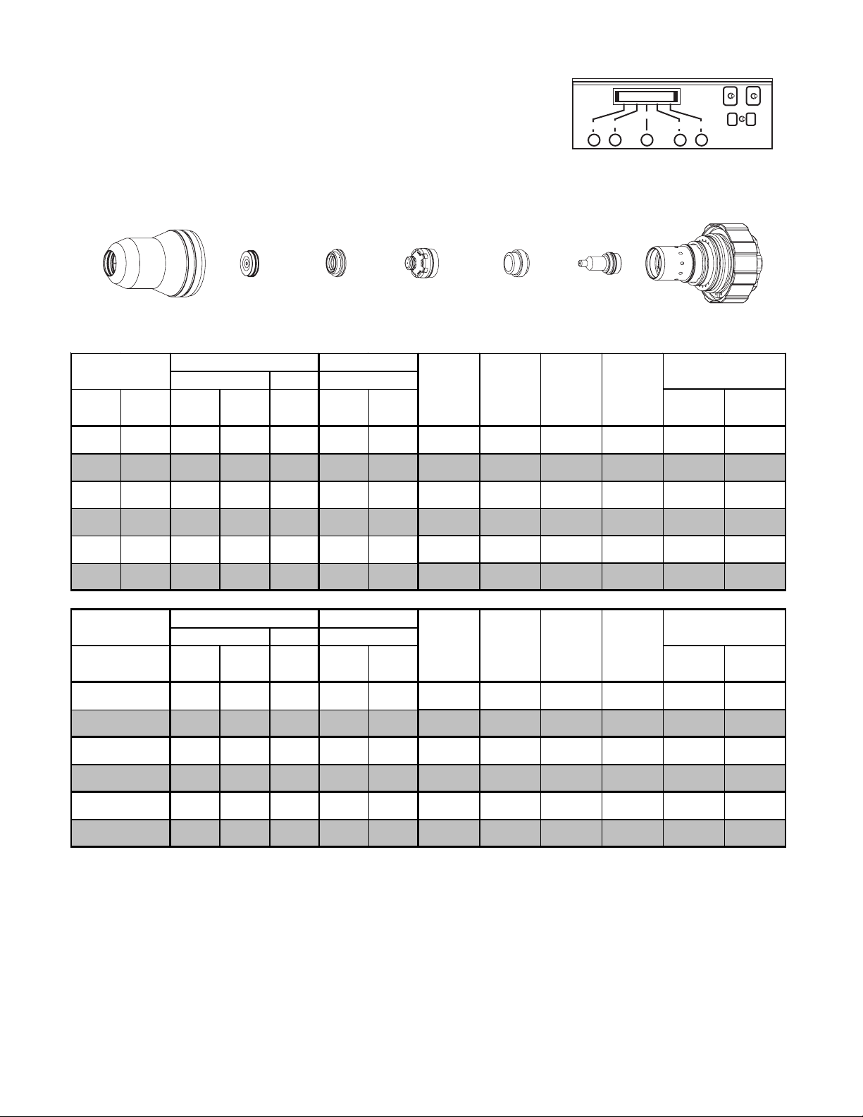
Stainless Steel
r
30A
1
3
2
4
5
Air Plasma / Air Shield
Shield Cup
21-1016
Material
Thi c k ness
(ga) (in)
Shield Cap
21-1033
Cut Flow Rates
Shield Preflow
Air
(1*)
Plasma
(2*)
Shield
Gas Distributor
21-1274
Preflow Flow
Air
(3*)
Air
(4*)
21-1059
(5*)
Tip
** Arc
Voltage
(volts )
Plasma
Gas Distributor
21-1045
Tor c h
Working
Height
(in)
Travel
Speed
(ipm)
21-1077
Initial
Piercing
Height
(in)
26 0.019 10 - 60 75 - 75 0.020 250 0.200 0.0 0.0
24 0.025 10 - 60 75 - 75 0.020 220 0.200 0.0 0.0
22 0.031 10 - 60 75 - 75 0.020 200 0.200 0.0 0.0
20 0.038 10 - 60 75 - 75 0.020 180 0.200 0.0 0.0
Cartridge
21-1020Electrode
Art # A-04498
Pierce Delay
(Dial) (s ec)
Art # A-06840
18 0.050 10 - 60 75 - 79 0.020 150 0.200 0.0 0.0
16 0.063 10 - 60 75 - 79 0.020 120 0.200 0.0 0.0
Material
Thi c k ness
(mm)
0.6
0.8
1.0
1.2
1.5
2.0
Cut Flow Rates
Shield Preflow
Air
(1*)
(2*)
10 - 60 75 - 75 0.5 5.8 5.0 0.0 0.0
10 - 60 75 - 75 0.5 5.1 5.0 0.0 0.0
10 - 60 75 - 75 0.5 4.6 5.0 0.0 0.0
10 - 60 75 - 79 0.5 3.9 5.0 0.0 0.0
10 - 60 75 - 79 0.5 3.3 5.0 0.0 0.0
10 - 60 75 - 79 0.5 2.0 5.0 0.0 0.1
* Refers to Control Knob Numbe
Plasma
Air
(3*)
Preflow Flow
Air
(4*)
(5*)
** Arc
Voltage
(volts )
Bold type
Tor c h
Working
Height
(mm)
Travel
Speed
(m/min)
Initial
Piercing
Height
(mm)
Pierce Delay
(Dial) (s ec)
indicates maximum piercing parameters.
Operation with 5-Knob Automatic Gas Console 4B-8 Manual 0-2912
Page 47

Stainless Steel
r
r
r
r
r
r
r
50A
Air Plasma / Air Shield
3
2
1
4
5
Art # A-06840
Shield Cup
21-1016
Material
Thickness
(ga) (in)
Shield
Shield Cap
21-1034
Cut Flow Rates
Shield Preflow
Ai
(1*)
(2*)
Gas Distributor
21-1274
Plasma
Ai
(3*)
Preflow Flow
Ai
(4*)
(5*)
Tip
21-1060
** Arc
Voltage
(volts)
Plasma
Gas Distributor
21-1041
Torch
Working
Height
(in)
Travel
Speed
(ipm)
21-1078
Initial
Piercing
Height
(in)
Cartridge
21-1020Electrode
Art # A-04029
Pierce Delay
(Dial) (sec)
14 0.075 80 - 65 65 - 113 0.060 120 0.120 0.0 0.0
12 0.105 80 - 65 65 - 117 0.060 80 0.150 0.0 0.0
10 0.135 80 - 65 65 - 121 0.060 55 0.180 0.0 0.1
- 0.188 80 - 65 65 - 123 0.080 40 0.250 1.0 0.3
Material
Thickness
(mm)
1.2
1.5
2.0
3.0
4.0
5.0
Cut Flow Rates
Shield Preflow
Ai
(1*)
(2*)
Plasma
Ai
(3*)
80 - 65 65 -
80 - 65 65 -
80 - 65 65 -
80 - 65 65 -
80 - 65 65 -
80 - 65 65 -
* Refers to Control Knob Numbe
Preflow Flow
Ai
(4*)
(5*)
Torch
** Arc
Voltage
(volts)
Working
Height
(mm)
Travel
Speed
(m/ min)
109 1.5 4.0 2.3
111 1.5 3.6 2.6
113 1.5 2.9 3.1
119 1.5 1.8 4.1
122 1.5 1.2 5.3
123 2.0 0.9 6.7
Bold type
indicates maximum piercing parameters.
Initial
Piercing
Height
(mm)
Pierce Delay
(Dial) (sec)
0.0
0.0
0.0
0.0
0.5
1.0
0.1
0.2
0.3
0
0
0
Manual 0-2912 4B-9 Operation with 5-Knob Automatic Gas Console
Page 48

Stainless Steel
r
70A
Air Plasma / Air - CH
Shield Cup
21-1016
Material
Thickness
(ga) (in)
Shield Cap
21-1035
Cut Flow Rates
Shield Preflow
Air
(1*)
CH
(2*)
4
Shield
4
Gas Distributor
Plasma
Air
(3*)
Shield
21-1274
Preflow Flow
Air
(4*)
CH
(5*)
Tip
21-1061
4
Voltage
Gas Distributor
** Arc
(volts)
Plasma
21-1041
Torch
Working
Height
(in)
1
Electrode
21-1079
Travel
Speed
(ipm)
3
2
Initial
Piercing
Height
(in)
4
5
Cartridge
21-1020
Art # A-04341
Pierce Delay
(Dial) (sec)
10 0.135 60 30 35 75 0 141 0.080 100 0.140 1.0 0.3
- 3/16 60 20 35 75 0 151 0.080 60 0.140 1.5 0.4
- 1/4 20 10 35 75 0 146 0.140 55 0.180 2.0 0.5
Art # A-06840
- 3/8 20 10 35 75 0 154 0.140 40 0.200 2.0 0.5
- 1/2 45 15 53 75 0 168 0.130 25 0.280 2.5 0.7
Cut Flow Rates
Material
Thickness
(mm)
1.5
2
3
4
5
6
8
10
12
Shield Preflow
Air
(1*)
CH
(2*)
20 10 35 75 0 140 2.0 3.2 3.0 0.5 0.2
20 10 35 75 0 141 2.0 3.0 3.5 0.5 0.2
20 10 35 75 0 143 2.0 2.5 4.0 0.5 0.2
20 10 35 75 0 145 2.0 2.0 4.5 0.5 0.2
20 10 35 75 0 146 2.0 1.6 5.0 0.5 0.2
20 10 35 75 0 146 4.0 1.4 5.0 0.5 0.2
20 10 35 75 0 146 4.0 1.2 5.0 0.5 0.2
20 10 35 75 0 154 4.0 1.0 5.0 2.0 0.5
45 15 53 75 0 168 3.9 0.9 7.0 2.5 0.7
* Refers to Control Knob Numbe
4
Plasma
Air
(3*)
Preflow Flow
Air
(4*)
CH
(5*)
4
Voltage
Bold type
** Arc
(volts)
Torch
Working
Height
(mm)
Travel
Speed
(m/ min)
Initial
Piercing
Height
(mm)
Pierce Delay
(Dial) (sec)
indicates maximum piercing parameters.
Operation with 5-Knob Automatic Gas Console 4B-10 Manual 0-2912
Page 49

Aluminum
r
r
r
50A
1
3
2
4
5
Air Plasma / Air Shield
Shield Cup
21-1016
Material
Thickness
(ga) (in)
Shield Cap
21-1034
Cut Flow Rates
Shield Preflow
Ai
(1)*
(2)*
Shield
Gas Distributor
21-1274
Plasma
Ai
(3)*
21-1060
Preflow Flow
Ai
(4)*
(5)*
Tip
Voltage
** Arc
(volts)
Plasma
Gas Distributor
21-1041
Torch
Working
Height
(in)
21-1078
Travel
Speed
(ipm)
Initial
Piercing
Height
(in)
14 0.075 80 - 65 65 - 135 0.100 135 0.150 0.0 0.0
12 0.105 80 - 65 65 - 139 0.105 90 0.200 0.0 0.0
10 0.135 80 - 65 65 - 142 0.110 60 0.200 0.0 0.0
- 3/16 80 - 65 65 - 145 0.120 40 0.250 0.5 0. 2
Cartridge
21-1020Electrode
Art # A-04029
Pierce Delay
(Dial) (sec)
Art # A-06840
Thickness
(mm)
0.6
0.8
1
1.2
1.5
2
3
4
5
Cut Flow Rates
Shield Preflow
Air
(1)* (2)*
Plasma
Air
(3)*
Preflow Flow
Air
(4)* (5)*
** Arc
Voltage
(volts)
Torch
Working
Height
(mm)
Travel
Speed
(m/ min)
Initial
Piercing
Height
(mm)
Pierce DelayMaterial
(Dial) (sec)
- 65 80 - 65 - 130 2.5 4.6 3.5 0.0
- 65 80 - 65 - 130 2.5 4.5 3.5 0.0
- 65 80 - 65 - 130 2.5 4.3 3.5 0.0
- 65 80 - 65 - 133 2.8 4.0 3.7 0.0
- 65 80 - 65 - 133 2.8 3.8 3.7 0.0
- 65 80 - 65 - 135 2.8 3.2 4.0 0.0
- 65 80 - 65 - 142 2.8 1.5 5.1 0.0
- 65 80 - 65 - 123 3.0 1.2 6.5 0.5
- 65 80 - 65 - 145 3.0 1.0 6.5 0.5
Bold type
indicates maximum piercing parameters.* Refers to Control Knob Number
Manual 0-2912 4B-11 Operation with 5-Knob Automatic Gas Console
Page 50

Aluminum
70A
1
3
2
Air Plasma / Air Shield
Shield Cup
21-1016
Material
Thickness
(ga) (in)
Shield Cap
21-1035
Cut Flow Rates
Shield Preflow
Ai r
(1*)
CH
(2*)
4
Shield
Gas Distributor
21-1274
Preflow Flow
Plasma
Air
(3*)
(4*)
Ai r
Rates
Tip
21-1061
CH
4
(5*)
12 0.097 65 0 35 63 0 132 0.080 200 0.140 0.0 0.1
- 1/8 65 0 35 63 0 140 0.100 110 0.140 0.0 0.1
- 3/16 65 0 35 63 0 144 0.120 100 0.140 0.0 0.1
Plasma
Gas Distributor
21-1041
** Arc
Working
Voltage
(volts)
Tor c h
Height
(in)
Electrode
21-1079
Travel
Speed
(ipm)
Initial
Piercing
Height
(in)
4
5
Cartridge
21-1020
Art # A-04341
Pierce Delay
(Dial) (sec)
Art # A-06840
- 1/4 65 0 35 63 0 148 0.140 70 0.180 0.5 0.2
- 3/8 65 0 35 63 0 152 0.140 40 0.180 1.0 0.3
Preflow Flow
Rates
Ai r
(4*)
CH
(5*)
4
** Arc
Voltage
(volts)
Tor c h
Working
Height
(mm)
Travel
Speed
(m/min)
Initial
Piercing
Height
(mm)
Pierce Delay
(Dial) (sec)
Material
Thickness
(mm)
2
3
4
5
6
8
10
Cut Flow Rates
Shield Preflow
Ai r
(1*)
CH
(2*)
4
Plasma
Air
(3*)
65 0 35 63 0 130 1.5 7.6 3.6 0.0 0.1
65 0 35 63 0 139 2.3 3.0 3.6 0.0 0.1
65 0 35 63 0 142 2.7 2.6 3.6 0.0 0.1
65 0 35 63 0 145 3.1 2.4 3.7 0.0 0.1
65 0 35 63 0 147 3.4 2.0 4.4 0.5 0.2
65 0 35 63 0 150 3.6 1.5 4.6 1.0 0.3
65 0 35 63 0 154 3.6 0.8 4.6 1.5 0.4
* Refers to Control Knob Number
Bold type
indicates maximum piercing parameters.
Operation with 5-Knob Automatic Gas Console 4B-12 Manual 0-2912
Page 51

SECTION 4C:
OPERATION WITH 6-KNOB AUTOMATIC GAS CONSOLE
4C.01 Torch Parts Selection
The application will determine which torch parts must be used. Refer to the speed charts in Section 4C.03, Recommended Cutting Speeds, for the proper torch parts to install for a selected application.
CAUTION
Do not interchange parts. Make sure all parts in the torch correspond with the plasma and shield gas in use for the
application.
4C.02 Pre-Setting Controls
A. Power Supply Setting
Set the Power Supply controls as follows before operating the system.
1. Set the proper cutting current at the AMPS thumbwheel.
2. Use data from the Speed Charts in Section 4.03 for each combination of material and amperage:
a. Set the initial torch height.
b. Set arc voltage on the torch height control.
c. Set the PIERCE DELAY potentiometer.
3. On the gas console select the plasma gas to be used with the PROCESS SELECTION switch.
4. All gas supplies are connected and set at 120 psi (8.3 bar) at the inlet pressure gauges.
B. Pre-Charge Box Setting
Before operating the system:
1. Set the gas supply pressure at the oxygen cylinder to 120 psi (8.3 bar).
2. On the front of the gas console set the RUN TEST switch to the TEST PREFLOW position. This will enable
gas to flow by opening the solenoid in the Pre-Charge Box.
3. If system plasma pressure gauge indicates more than 120 psi (8.3 bar) the system is over pressurized. Stop
and do the following:
a. On the front of the gas console set the RUN TEST switch to the TEST CUT FLOW position.
b. Let gas flow for 20 seconds. This will allow the system pressure to bleed off.
c. Repeat steps 2 and 3 above.
Manual 0-2912 4C-1 Operation with 6-Knob Automatic Gas Console
Page 52

4C.03 Recommended Cutting Speeds
!
Cutting speed depends on material and thickness. The following factors may affect system performance:
• Torch parts wear
• Speed
• Gas quality
• Operator experience
• Torch standoff height
• Proper work cable connection
• Alloy content of material
NOTE
This information represents realistic expectations using recommended practices and well-maintained systems. Actual speeds may vary from those shown in the charts depending on the alloy content of the selected material.
For complete cutting speed chart data refer to the following pages.
CAUTION
Information in this section is for the HD3070 System with an automatic gas control with 6 control knobs.
1
Preflow Controls
2
3
Shield Controls
4
5
6
Plasma Controls
Art # A-04494
Operation with 6-Knob Automatic Gas Console 4C-2 Manual 0-2912
Page 53

NOTES
** - Arc voltage is based on 50 ft (15.2 m) torch lead length. For other lead lengths the operator may need to adjust
the Arc Voltage setting. Refer to Appendix 1 for Alternate Arc Voltage Settings.
NOTE: The preflow rates shown generate increased dross at the start of a cut. Increasing the amount of oxygen and
reducing the amount of nitrogen will reduce dross at the start of a cut, but will also reduce electrode life.
Oxygen (O2) gas inlet pressures must be 120 psi (8.3 bar) for all material thicknesses.
Slightly increasing the preflow flow rates may increase piercing capability on the thicker materials listed above.
However, increasing the preflow flow rates too much may affect plasma starting reliability (misfiring).
Torch Working Height tolerances are ±0.005 inch (±0.125 mm).
Thermal Dynamics Pre-Charge Unit must be installed before cutting.
Chart gives set-up parameters for use with a Hypertherm HD 3070 System. For technical and legal reasons the
settings in the chart may not be appropriate for use with other systems.
Manual 0-2912 4C-3 Operation with 6-Knob Automatic Gas Console
Page 54

Mild Steel
30A
Plasma / O2 - N2 Shield
O
2
Shield Cup
21-1016
Preflow Flow
Material
Thickness
(ga) (in)
(1*)
Shield Cap
21-1024
Rates
Preflow Shield Plasma
O
N2
2
(2*)
Gas Distributor
Cut Flow Rates
O
2
(3*)
Shield
21-1082
N2
(4*)
O
(5*)
2
Tip
21-1050
(6*)
Plasma
Gas Distributor
21-1040
Tor c h
** Arc
Voltage
Working
Height
(volts)
(in)
Electrode
21-1068
Travel
Speed
(ipm)
2
1
Piercing
3
Initial
Height
(in)
5
4
6
Cartridge
21-1020
Art # A-04338
Pierce Delay
(Dial) (Sec)
20 0.036 5 55 13 0 13 - 129 0.050 140 0.120 0.5 0.2
16 0.060 5 55 13 0 13 - 137 0.050 80 0.120 0.5 0.2
14 0.075 5 55 13 0 13 - 139 0.070 50 0.120 0.5 0.2
Art # A-06841
11 0.120 5 55 17 3 13 - 140 0.070 40 0.120 0.5 0.2
10 0.135 5 55 17 3 13 - 142 0.070 35 0.120 0.5 0.2
9 0.150 5 55 17 3 13 - 143 0.070 33 0.120 1.0 0.3
7 0.179 5 55 17 3 13 - 144 0.070 30 0.120 1.0 0.3
Preflow Flow
Rates
Cut Flow Rates
Material
Thickness
(mm)
0.6
0.8
1
1.2
1.5
2
3
Preflow Shield Plasma
O
(1*)
N2
2
(2*)
O
(3*)
N2
2
(4*)
O
2
(5*) (6*) (Dial) (Sec)
** Arc
Voltage
(volts)
Tor c h
Working
Height
(mm)
Travel
Speed
(m/min)
5 55 13 0 13 - 125 1.3 4.8 3.0 0.0 0.1
5 55 13 0 13 - 125 1.3 4.1 3.0 0.0 0.1
5 55 13 0 13 - 129 1.3 3.6 3.0 0.0 0.1
5 55 13 0 13 - 129 1.3 2.9 3.0 0.0 0.1
5 55 13 0 13 - 136 1.3 2.2 3.0 0.5 0.2
5 55 13 0 13 - 139 1.8 1.3 3.0 0.5 0.2
5 55 17 3 13 - 140 1.8 1.1 3.0 0.5 0.2
Initial
Piercing
Height
(mm)
Pierce Delay
4
5
* Refers to Control Knob Number
5 55 17 3 13 - 142 1.8 0.9 3.0 0.5 0.2
5 55 17 3 13 - 145 1.8 0.7 3.0 1.0 0.3
Bold type
indicates maximum piercing parameters.
Operation with 6-Knob Automatic Gas Console 4C-4 Manual 0-2912
Page 55

Mild Steel
50A
Plasma / O2 - N2 Shield
O
2
Shield Cup
21-1016
Material
Thi c k ness
(ga) (in)
Shield Cap
21-1025
Preflow Flow
Rates
Preflow Shield Plasma Torch
O
(1*)
N2
2
(2*)
Shield
Gas Distributor
21-1272
Cut Flow Rates
O
(3*)
N2
2
(4*)
O
(5*)
2
Tip
21-1051
(6*)
Plasma
Gas Distributor
21-1041
** Arc
Voltage
Working
Height
(volts )
(in)
Electrode
21-1069
Travel
Speed
(ipm)
2
1
3
4
Initial
Piercing
Height
(in)
5
6
Cartridge
21-1020
Art # A-04026
Pierce Delay
(Dial) (s ec)
20 0.036 10 40 5 25 20 - 122 0.060 500 0.100 1.0 0.3 *
16 0.060 10 40 5 25 20 - 126 0.060 300 0.100 1.0 0.3 *
10 0.135 10 40 5 25 20 - 130 0.060 150 0.200 0.0 0.1
7 0.179 5 65 5 25 20 - 134 0.080 100 0.200 0.0 0.1
Art # A-06841
1/4 5 65 5 25 20 - 135 0.100 80 0.200 0.0 0.1
3/8 5 65 5 15 20 - 148 0.110 25 0.350 1.0 0.3
Material
Thi c k ness
(mm)
0.8
1.0
1.2
1.5
2.0
3.0
4.0
5.0
Preflow Flow
Rates
Preflow Shield Plasma
O
(1*)
N2
2
(2*)
Cut Flow Rates
O
2
(3*)
N2
(4*)
O
(5*)
Torch
** Arc
2
(6*)
Voltage
(volts )
Working
Height
(mm)
Travel
Speed
(m/min)
Initial
Piercing
Height
(mm)
Pierce Delay
(Dial) (s ec)
10 40 5 25 20 - 122 1.5 12.7 2.5 1.0 0.3 *
10 40 5 25 20 - 123 1.5 12.0 2.5 1.0 0.3 *
10 40 5 25 20 - 124 1.5 9.5 2.5 1.0 0.3 *
10 40 5 25 20 - 126 1.5 7.6 2.5 1.0 0.3 *
10 40 5 25 20 - 127 1.5 6.5 3.3 0.5 0.2 *
10 40 5 25 20 - 130 1.5 3.8 4.8 0.0 0.1
10 40 5 25 20 - 132 2.0 3.1 5.0 0.0 0.1
5 65 5 25 20 - 134 2.0 2.5 5.1 0.0 0.1
6.0
8.0
10.0
* Refers to Control Knob Number
5 65 5 25 20 - 135 2.0 2.1 5.1 0.0 0.1
5 65 5 15 20 - 146 2.5 0.8 6.4 0.5 0.2
5 65 5 15 20 - 148 2.8 0.6 8.9 1.0 0.3
Bold type
indicates maximum piercing parameters.
Manual 0-2912 4C-5 Operation with 6-Knob Automatic Gas Console
Page 56

Mild Steel
70A
Plasma / O2 - N2 Shield
O
2
Shield Cup
21-1016
Material
Thickness
(ga) (in)
Shield Cap
21-1026
Preflow Flow
Rates
Preflow Shield Plasma
O
(1*)
N2
2
(2*)
Shield
Gas Distributor
21-1272
Cut Flow Rates
O
(3*)
N2
2
(4*)
Tip
21-1052
O
2
(5*) (6*)
Plasma
Gas Distributor
21-1041
Torch
** Arc
Voltage
Working
Height
(volts)
(in)
21-1070
Travel
Speed
(ipm)
2
1
Piercing
Height
3
Initial
(in)
5
4
6
Cartridge
21-1020Electrode
Art # A-04027
Pierce Delay
(Dial) (sec)
16 0.060 5 65 25 0 25 - 138 0.060 300 0.100 0.0 0.0
14 0.075 5 65 25 0 25 - 138 0.060 250 0.100 0.0 0.0
Art # A-06841
12 0.105 5 65 10 45 65 - 140 0.060 225 0.120 0.0 0.0
10 0.135 5 65 10 45 65 - 142 0.060 200 0.150 0.0 0.0
7 0.179 5 65 10 45 65 - 143 0.070 120 0.200 0.0 0.1
- 1/4 5 65 10 45 65 - 146 0.080 110 0.200 0.5 0.2
- 3/8 5 65 10 45 65 - 150 0.120 70 0.300 0.5 0.2
Preflow Flow
Rates
Cut Flow Rates
Material
Thickness
(mm)
1.5
2
3
4
5
6
Preflow Shield Plasma
** Arc
O
(1*)
N2
2
(2*)
O
(3*)
N2
2
(4*)
O
(5*)
2
(6*)
Voltage
(volts)
5 65 25 0 25 - 138 1.5 7.6 2.5 0.0 0.0
5 65 25 0 25 - 138 1.5 6.8 2.5 0.0 0.0
5 65104565 - 141 1.5 5.3 3.70.00.0
5 65104565 - 141 1.5 4.1 3.70.00.0
5 65104565 - 144 1.9 3.0 5.20.00.0
5 65104565 - 146 1.9 2.5 5.20.00.0
Torch
Working
Height
(mm)
Travel
Speed
(m/min)
Initial
Piercing
Height
(mm)
Pierce Delay
(Dial) (sec)
8
* Refers to Control Knob Number
5 65104565 - 148 2.5 2.3 6.40.50.1
Bold type
indicates maximum piercing parameters.
Operation with 6-Knob Automatic Gas Console 4C-6 Manual 0-2912
Page 57

Mild Steel
100A
Plasma / O2 - N2 Shield
O
2
Shield Cup
21-1016
Material
Thickness
(ga) (in)
Shield Cap
21-1027
Preflow Flow
Rates
Preflow Shield Plasma
O
(1*)
N2
2
(2*)
Shield
Gas Distributor
21-1272
Cut Flow Rates
O
(3*)
N2
2
(4*)
O
(5*)
2
Tip
21-1053
(6*)
Plasma
Gas Distributor
21-1041
Torch
** Arc
Voltage
Working
Height
(volts)
(in)
Electrode
21-1071
Travel
Speed
(ipm)
2
1
Piercing
Height
3
Initial
(in)
5
4
6
Cartridge
21-1020
Art # A-04028
Pierce Delay
(Dial) (s ec)
10 0.135 15 80 15 70 62 - 141 0.070 280 0.200 0.0 0.0
7 0.179 15 80 15 70 62 - 145 0.090 235 0.200 0.0 0.0
- 1/4 15 80 15 70 62 - 153 0.100 150 0.200 0.0 0.0
Art # A-06841
- 3/8 15 80 15 70 62 - 156 0.110 100 0.250 0.5 0.2
- 1/2 15 80 15 86 62 - 158 0.120 70 0.300 1.0 0.3
- 5/8 15 80 15 86 62 - 163 0.120 50 0.350 2.0 0.5
- 3/4 15 80 15 86 62 - 176 0.150 25 0.400 2.5 0.6
Material
Thickness
(mm)
3
4
5
6
8
10
12
Preflow Flow
Rates
Preflow Shield Plasma
O
(1*)
N2
2
(2*)
15 80 15 70 62 - 142 2.3 6.2 4.5 0.0 0.0
15 80 15 70 62 - 145 2.3 5.7 4.8 0.0 0.0
15 80 15 70 62 - 148 2.3 5.3 5.1 0.0 0.0
15 80 15 70 62 - 152 2.3 4.6 5.1 0.0 0.0
15 80 15 70 62 - 155 2.8 3.2 5.8 0.0 0.1
15 80 15 70 62 - 156 3.0 2.1 6.6 0.5 0.2
15 80 15 86 62 - 158 3.0 1.9 7.1 1.0 0.3
Cut Flow Rates
O
2
(3*)
N2
(4*)
O
2
(5*) (6*)
** Arc
Voltage
(volts)
Torch
Working
Height
(mm)
Travel
Speed
(m/min)
Initial
Piercing
Height
(mm)
Pierce Delay
(Dial) (s ec)
15
20
* Refers to Control Knob Number
15 80 15 86 62 - 162 3.0 1.2 8.4 1.5 0.4
15 80 15 86 62 - 176 3.8 0.6 10.2 1.5 0.4
Bold type
indicates maximum piercing parameters.
Manual 0-2912 4C-7 Operation with 6-Knob Automatic Gas Console
Page 58

Stainless Steel
30A
2
1
5
3
4
6
Air Plasma / Air Shield
Shield Cup
21-1016
Material
Thickness
(ga) (in)
Shield Cap
21-1033
Preflow Flow
Preflow Shield Plasma
Air
(1*)
(2*)
Shield
Gas Distributor
21-1274
Cut Flow Rates
Air
(3*)
(4*)
21-1059
Air
(5*)
Tip
(6*)
Plasma
Gas Distributor
21-1045
** Arc
Voltage
(volts)
Torch
Working
Height
(in)
21-1077
Travel
Speed
(ipm)
Piercing
26 0.019 75 - 10 - 60 - 75 0.020 250 0.200 0.0 0.0
24 0.025 75 - 10 - 60 - 75 0.020 220 0.200 0.0 0.0
22 0.031 75 - 10 - 60 - 75 0.020 200 0.200 0.0 0.0
20 0.038 75 - 10 - 60 - 75 0.020 180 0.200 0.0 0.0
Initial
Height
(in)
Cartridge
21-1020Electrode
Art # A-04498
Pierce Delay
(Dial) (sec)
Art # A-06841
18 0.050 75 - 10 - 60 - 79 0.020 150 0.200 0.0 0.0
16 0.063 75 - 10 - 60 - 79 0.020 120 0.200 0.0 0.0
Preflow Flow
Material
Thickness
(mm)
0.6
0.8
1.0
1.2
1.5
2.0
Preflow Shield Plasma
Air
(1*)
(2*)
75 - 10 - 60 - 75 0.5 5.8 5.0 0.0 0.0
75 - 10 - 60 - 75 0.5 5.1 5.0 0.0 0.0
75 - 10 - 60 - 75 0.5 4.6 5.0 0.0 0.0
75 - 10 - 60 - 79 0.5 3.9 5.0 0.0 0.0
75 - 10 - 60 - 79 0.5 3.3 5.0 0.0 0.0
75 - 10 - 60 - 79 0.5 2.0 5.0 0.0 0.1
* Refers to Control Knob Number
Cut Flow Rates
Air
(3*)
(4*)
Air
(5*)
(6*)
** Arc
Voltage
(volts)
Bold type
Torch
Working
Height
(mm)
Travel
Speed
(m/min)
Initial
Piercing
Height
(mm)
Pierce Delay
(Dial) (sec)
indicates maximum piercing parameters.
Operation with 6-Knob Automatic Gas Console 4C-8 Manual 0-2912
Page 59

Stainless Steel
r
r
r
r
50A
2
1
5
3
4
6
Air Plasma / Air Shield
Shield Cup
21-1016
Material
Thickness
(ga) (in)
Shield Cap
21-1034
Preflow Flow
Preflow Shield Plasma
Air
(1*)
(2*)
Shield
Gas Distributor
21-1274
Cut Flow Rates
Ai
(3*)
(4*)
21-1060
Ai
(5*)
Tip
Gas Distributor
Voltage
(6*)
Plasma
21-1041
** Arc
(volts)
Torch
Working
Height
(in)
21-1078
Travel
Speed
(ipm)
14 0.075 65 - 80 - 65 - 113 0.060 120 0.120 0.0 0.0
12 0.105 65 - 80 - 65 - 117 0.060 80 0.150 0.0 0.0
10 0.135 65 - 80 - 65 - 121 0.060 55 0.180 0.0 0.1
- 3/16 65 - 80 - 65 - 123 0.080 40 0.250 1.0 0.3
Initial
Piercing
Height
(in)
Cartridge
21-1020Electrode
Art # A-04029
Pierce Delay
(Dial) (s ec)
Art # A-06841
Cut Flow Rates
Ai
(3*)
(4*)
Ai
(5*)
(6*)
Torch
** Arc
Voltage
(volts)
Working
Height
(mm)
Travel
Speed
(m/min)
109 1.5 4.0 2.3
111 1.5 3.6 2.6
113 1.5 2.9 3.1
119 1.5 1.8 4.1
122 1.5 1.2 5.3
123 2.0 0.9 6.7
Initial
Piercing
Height
(mm)
Pierce Delay
(Dial) (s ec)
0.0
0.0
0.0
0.0
0.5
1.0
0
0
0
0.1
0.2
0.3
Material
Thickness
(mm)
1.2
1.5
2
3
4
5
Preflow Flow
Preflow Shield Plasma
Air
(1*)
(2*)
65 - 80 - 65 -
65 - 80 - 65 -
65 - 80 - 65 -
65 - 80 - 65 -
65 - 80 - 65 -
65 - 80 - 65 -
* Refers to Control Knob Number Bold type indicates maximum piercing parameters.
Manual 0-2912 4C-9 Operation with 6-Knob Automatic Gas Console
Page 60

Stainless Steel
70A
Air Plasma / Air - CH
Shield Cup
21-1016
Material
Thickness
(ga) (in)
Preflow Flow
Shield Cap
21-1035
Preflow Shield Plasma
Air
(1*)
CH
(2*)
4
Shield
4
Gas Distributor
Cut Flow Rates
Air
(3*)
Shield
21-1274
CH
4
(4*)
Air
(5*)
Tip
21-1061
(6*)
Plasma
Gas Distributor
21-1041
Tor c h
** Arc
Voltage
(volts)
Working
Height
(in)
Electrode
21-1079
Travel
Speed
(ipm)
2
1
Initial
Piercing
Height
3
(in)
5
4
6
Cartridge
21-1020
Art # A-04341
Pierce Delay
(Dial) (sec)
10 0.135 75 0 60 30 35 - 141 0.080 100 0.140 1.0 0.3
- 3/16 75 0 60 20 35 - 151 0.080 60 0.140 1.5 0.4
- 1/4 75 0 20 10 35 - 146 0.140 55 0.180 2.0 0.5
- 3/8 75 0 20 10 35 - 154 0.140 40 0.200 2.0 0.5
Art # A-06841
- 1/2 75 0 45 15 53 - 168 0.130 25 0.280 2.5 0.7
Preflow Flow
Material
Thickness
(mm)
1.5
2
3
4
5
6
8
10
12
Preflow Shield Plasma
Air
(1*)
CH
(2*)
4
75 0 20 10 35 - 140 2.0 3.2 3.0 0.5 0.2
75 0 20 10 35 - 141 2.0 3.0 3.5 0.5 0.2
75 0 20 10 35 - 143 2.0 2.5 4.0 0.5 0.2
75 0 20 10 35 - 145 2.0 2.0 4.5 0.5 0.2
75 0 20 10 35 - 146 2.0 1.6 5.0 0.5 0.2
75 0 20 10 35 - 146 4.0 1.4 5.0 0.5 0.2
75 0 20 10 35 - 146 4.0 1.2 5.0 0.5 0.2
75 0 20 10 35 - 154 4.0 1.0 5.0 2.0 0.5
75 0 45 15 53 - 168 3.9 0.9 7.0 2.5 0.7
* Refers to Control Knob Number
Cut Flow Rates
Air
(3*)
CH
(4*)
Tor c h
** Arc
Air
4
(5*)
(6*)
Voltage
(volts)
Bold type
Working
Height
(mm)
indicates maximum piercing parameters.
Travel
Speed
(m/min)
Initial
Piercing
Height
(mm)
Pierce Delay
(Dial) (sec)
Operation with 6-Knob Automatic Gas Console 4C-10 Manual 0-2912
Page 61

Stainless Steel
100A
2
1
5
3
4
6
Ar/H2 Plasma / N2 Shield
Shield Cup
21-1016
Material
Thickness
(ga) (in)
Shield Cap
21-1036
Preflow Flow
Preflow Shield Plasma
N2
(1*)N2(2*)
Shield
Gas Distributor
21-1274
Cut Flow Rates
N2
(3*)
N2
(4*)
N2
(5*)
Tip
21-1062
H35
(6*)
Plasma
Gas Distributor
21-1041
** Arc
Voltage
(volts)
Torch
Working
Height
(in)
Electrode
21-1080
Travel
Speed
(ipm)
Piercing
Height
- 1/8 35 35 35 35 35 0 148 0.125 80 0.200 0.0 0.1
- 1/4 35 35 35 35 35 35 161 0.125 65 0.250 1.0 0.3
- 3/8 35 35 35 35 35 35 161 0.125 60 0.300 1.0 0.3
- 1/2 35 35 35 35 35 35 161 0.130 50 0.350 2.0 0.5
Initial
(in)
Cartridge
21-1020
Art # A-04030
Pierce Delay
(Dial) (sec)
Art # A-06841
- 5/8 35 35 35 35 35 35 169 0.140 30 0.350 3.0 0.8
Preflow Flow
Thickness
(mm)
3
4
5
6
8
10
12
15
Preflow Shield Plasma
N2
(1*)N2(2*)
35 35 35 35 35 0 148 3.2 2.0 5.1 0.0 0.1
35 35 35 35 35 35 155 3.2 1.9 6.0 1.0 0.3
35 35 35 35 35 35 161 3.2 1.8 6.4 1.0 0.3
35 35 35 35 35 35 161 3.2 1.7 6.4 1.0 0.3
35 35 35 35 35 35 161 3.2 1.6 6.4 1.0 0.3
35 35 35 35 35 35 161 3.2 1.5 7.6 1.5 0.4
35 35 35 35 35 35 161 3.3 1.3 8.9 2.0 0.5
35 35 35 35 35 35 167 3.6 0.9 8.9 2.7 0.7
* Refers to Control Knob Number
Cut Flow Rates
N2
(3*)
N2
(4*)
N2
(5*)
H35
(6*)
** Arc
Voltage
(volts)
Bold type
Torch
Working
Height
(mm)
Travel
Speed
(m/min)
Initial
Piercing
Height
(mm)
Pierce DelayMaterial
(Dial) (sec)
indicates maximum piercing parameters.
Manual 0-2912 4C-11 Operation with 6-Knob Automatic Gas Console
Page 62

Aluminum
r
r
r
r
r
r
50A
2
1
5
3
4
6
Air Plasma / Air Shield
Shield Cup
21-1016
Material
Thickness
(ga) (in)
Shield Cap
21-1034
Preflow Flow
Preflow Shield Plasma
Ai
(1)*
(2)*
Shield
Gas Distributor
21-1274
Cut Flow Rates
Ai
(3)*
(4)*
21-1060
Ai
(5)*
Tip
(6)*
Plasma
Gas Distributor
21-1041
Torch
** Arc
Voltage
(volts)
Working
Height
(in)
21-1078
Travel
Speed
(ipm)
Piercing
14 0.075 - 65 80 - 65 - 135 0.100 135 0.150 0.0 0.0
12 0.105 - 65 80 - 65 - 139 0.105 90 0.200 0.0 0.0
10 0.135 - 65 80 - 65 - 142 0.110 60 0.200 0.0 0.0
- 3/16 - 65 80 - 65 - 145 0.120 40 0.250 0.5 0.2
Initial
Height
(in)
Cartridge
21-1020Electrode
Art # A-04029
Pierce Delay
(Dial) (sec)
Art # A-06841
Preflow Flow
Material
Thickness
(mm)
0.6
0.8
1
1.2
1.5
2
3
4
5
Preflow Shield Plasma
Ai
(1)*
(2)*
- 65 80 - 65 - 130 2.5 4.6 3.5 0.0 0.0
- 65 80 - 65 - 130 2.5 4.5 3.5 0.0 0.0
- 65 80 - 65 - 130 2.5 4.3 3.5 0.0 0.0
- 65 80 - 65 - 133 2.8 4.0 3.7 0.0 0.0
- 65 80 - 65 - 133 2.8 3.8 3.7 0.0 0.0
- 65 80 - 65 - 135 2.8 3.2 4.0 0.0 0.0
- 65 80 - 65 - 142 2.8 1.5 5.1 0.0 0.0
- 65 80 - 65 - 123 3.0 1.2 6.5 0.5 0.2
- 65 80 - 65 - 145 3.0 1.0 6.5 0.5 0.2
* Refers to Control Knob Number
Cut Flow Rates
Ai
(3)*
(4)*
Ai
(5)*
(6)*
** Arc
Voltage
(volts)
Bold type
Torch
Working
Height
(mm)
Travel
Speed
(m/min)
Initial
Piercing
Height
(mm)
Pierce Delay
(Dial) (sec)
indicates maximum piercing parameters.
Operation with 6-Knob Automatic Gas Console 4C-12 Manual 0-2912
Page 63

Aluminum
70A
2
1
5
3
4
6
Air Plasma / Air Shield
Initial
Height
(in)
Cartridge
21-1020
Art # A-04341
Pierce Delay
(Dial) (sec)
Shield Cup
21-1016
Material
Thickness
(ga) (in)
Shield
Shield Cap
21-1035
Preflow Flow
Rates
Gas Distributor
21-1274
Cut Flow Rates
Preflow Shield Plasma
Air
(1*)
CH
(2*)
Air
4
(5*)
CH
(6*)
Air
4
(3*)
Tip
21-1061
(4*)
Plasma
Gas Distributor
21-1041
Torch
** Arc
Voltage
Working
Height
(volts)
(in)
Electrode
21-1079
Travel
Speed
(ipm)
Piercing
12 0.097 63 0 65 0 35 - 132 0.080 200 0.140 0.0 0.1
- 1/8 63 0 65 0 35 - 140 0.100 110 0.140 0.0 0.1
- 3/16 63 0 65 0 35 - 144 0.120 100 0.140 0.0 0.1
- 1/4 63 0 65 0 35 - 148 0.140 70 0.180 0.5 0.2
Art # A-06841
- 3/8 63 0 65 0 35 - 152 0.140 40 0.180 1.0 0.3
Material
Thickness
(mm)
2
3
4
5
6
8
10
Preflow Flow
Rates
Preflow Shield Plasma
Air
(1*)
CH
(2*)
4
63 0 65 0 35 - 130 1.5 7.6 3.6 0.0 0.1
63 0 65 0 35 - 139 2.3 3.0 3.6 0.0 0.1
63 0 65 0 35 - 142 2.7 2.6 3.6 0.0 0.1
63 0 65 0 35 - 145 3.1 2.4 3.7 0.0 0.1
63 0 65 0 35 - 147 3.4 2.0 4.4 0.5 0.2
63 0 65 0 35 - 150 3.6 1.5 4.6 1.0 0.3
63 0 65 0 35 - 154 3.6 0.8 4.6 1.5 0.4
Cut Flow Rates
Air
(5*)
CH
(6*)
Torch
** Arc
Air
4
(3*)
(4*)
Voltage
(volts)
Working
Height
(mm)
Travel
Speed
(m/min)
Initial
Piercing
Height
(mm)
Pierce Delay
(Dial) (sec)
* Refers to Control Knob Number
Bold type
indicates maximum piercing parameters.
Manual 0-2912 4C-13 Operation with 6-Knob Automatic Gas Console
Page 64

Aluminum
100A
2
1
5
3
4
6
Ar/H2 Plasma / N2 Shield
Shield Cup
21-1016
Material
Thickness
(ga) (in)
Shield Cap
21-1036
Preflow Flow
Preflow Shield Plasma
N2
(1*)
N2
(2*)N2(3*)
Shield
Gas Distributor
21-1274
Cut Flow Rates
N2
(4*)
H35
(5*)
Tip
21-1062
N2
(6*)
Plasma
Gas Distributor
21-1041
Torch
** Arc
Voltage
Working
Height
(volts)
(in)
Electrode
21-1080
Travel
Speed
(ipm)
Piercing
- 1/4 35 35 35 35 35 35 161 0.150 100 0.350 0.5 0.2
- 3/8 35 35 35 35 35 35 163 0.150 60 0.350 0.5 0.2
- 1/2 35 35 35 35 35 35 166 0.150 50 0.350 1.0 0.3
- 5/8 35 35 35 35 60 30 173 0.150 40 0.400 2.0 0.5
Initial
Height
(in)
Cartridge
21-1020
Art # A-04030
Pierce Delay
(Dial) (sec)
Art # A-06841
Preflow Flow
Material
Thickness
(mm)
3
4
5
6
8
10
12
15
Preflow Shield Plasma
N2
(1*)
N2
(2*)N2(3*)
35 35 35 35 35 35 155 3.8 3.3 8.0 0.5 0.2
35 35 35 35 35 35 158 3.8 3.0 8.0 0.5 0.2
35 35 35 35 35 35 160 3.8 2.8 8.9 0.5 0.2
35 35 35 35 35 35 160 3.8 2.5 8.9 0.5 0.2
35 35 35 35 35 35 162 3.8 2.0 8.9 0.5 0.2
35 35 35 35 35 35 163 3.8 1.5 8.9 0.5 0.2
35 35 35 35 35 35 165 3.8 1.3 8.9 1.0 0.3
35 35 35 35 60 30 172 3.8 1.1 10.2 2.0 0.5
* Refers to Control Knob Number
Cut Flow Rates
N2
(4*)
H35
(5*)
N2
(6*)
** Arc
Voltage
(volts)
Bold type
Torch
Working
Height
(mm)
Travel
Speed
(m/min)
Initial
Piercing
Height
(mm)
Pierce Delay
(Dial) (sec)
indicates maximum piercing parameters.
Operation with 6-Knob Automatic Gas Console 4C-14 Manual 0-2912
Page 65

Section 5: General Maintenance
A. O-Ring Lubrication
Lubricate all three O-Rings on the Cartridge Assembly and all three O-Rings on the Torch Head periodically
with O-Ring Lubricant supplied. Remove the snap ring on the cartridge assembly and slide the locking ring
downward for access to the O-Ring under the locking ring.
Inner O-Ring (Cat. No. 8-0545)
Location (Under Locking Ring)
O-Ring, Cat. No. 8-0544
O-Ring, Cat. No. 8-0540
Cartridge Assembly
Snap Ring
Art # A-04071
Cat. No. 9-9041
Cat. No. 8-0539
Cat. No. 8-0534
Cat. No. 8-0530
O-Rings
Torch Head
Art # A-04066
CAUTION
Use only Thermal Dynamics No. 9-4893 O-Ring Lubricant (Christo Lube MCG-129) with this torch part. Use of
other lubricants may cause irreparable damage to the torch.
B Consumable Removal
1. Use the removal tool to hold the Shield Cup & Cartridge Assembly stationary. Turn the Shield Cup to
remove it from the Cartridge Assembly
Cartridge Tool
Assembled Cartridge
Art # A-04344
Shield Cup
Manual 0-2912 5-1 Maintenance
Page 66

2. Take the Removal Tool off the back of the Cartridge Assembly Use the removal tool to push the consumable
parts out of the Shield Cup.
Cartridge Tool
Shield Cup
Assembled Cartridge
Art # A-04035
C. Gas Distributor
Replace the Gas Distributor if it is charred or cracked.
Replace the Gas Distributor if flange is damaged in any way.
D. Electrode Replacement
Replace the Electrode when the insert has become worn per the chart.
Art # A-04713
Amperage
30
50
70
100
150
Plasma
Gas
Recommended Wear Depth
for Replacement
Inch mm
O
2
0.04 1
Air 0.04 1
O
2
0.04 1
Air 0.08 2
O
2
0.04 1
Air 0.08 2
O
2
0.04 1
H35 0.08 2
O
2
0.08 2
H35 0.08 2
Maintenance 5-2 Manual 0-2912
Page 67

Install Consumable Torch Parts
WARNINGS
Do not install consumables into the Cartridge
while the Cartridge is attached to the Torch Head.
Keep foreign materials out of the consumables and Cartridge.
Handle all parts carefully to avoid damage,
which may affect torch performance.
Art # A-03887
1. Check the appropriate cut chart for the right combination of parts for the cutting application.
2. Install the consumable parts as follows to ensure proper operation. These steps will help ensure that parts
are seated correctly.
Electrode
Plasma Gas
Distributor
Tip
Shield Gas
Distributor
Shield Cap
3: Thread Shield Cup onto Cartridge
1: Stack Parts
Upper O-Ring
on Tip
2: Press Cartridge onto Stacked Parts
No Gaps
Between Parts
Cartridge Covers
Upper O-Ring
on Torch Tip
4: Check Shield Cap Protrusion
Shield Cup
Shield Cap
Shield Cap Protrudes
0.063-0.083" (1.6 - 2.1 mm)
Art # A-04716
Manual 0-2912 5-3 Maintenance
Page 68

3. Use the removal tool to hold the cartridge assembly, while turning the shield cup onto the cartridge
assembly. When this group is fully assembled, the shield should protrude from the front of the shield
cup 0.063" to 0.083" (1.6 - 2.1 mm). Without this protrusion the shield cup is not properly tightened
onto the cartridge assembly.
4. Take the removal tool off the cartridge. Fit the cartridge assembly onto the torch head. The cartridge should
seal to the large O-ring on the torch body as shown. If the cartridge does not seal on the O-ring, the cartridge
is not fully tightened.
CAUTION
Do not force the cartridge if it will not fully tighten. Remove the cartridge and gently clean the threads on the torch
head body with a wire brush. Apply oxygen-compatible lubricant (supplied with the torch) to the threads.
Torch Head
0.063 - 0.083"
(1.6 - 2.1 mm)
Protrusion
Installing Assembled Cartridge Onto Torch Head
5. Slide the ohmic clip over the shield cup if using ohmic torch height sensing.
Torch Head O-Ring
Art # A-07202
Ohmic Clip
A-03393
6. Connect the wire lead from the height finder to the ohmic clip if using ohmic torch height sensing.
7. Connect the wire lead from the height finder to the ohmic clip.
Maintenance 5-4 Manual 0-2912
Page 69

E. Coolant Leak Trouble-Shooting
Never operate the system if coolant leaks from the torch. A steady drip indicates that torch parts are damaged or
installed improperly. Operating the system in this condition can damage the torch head. Refer to the following chart
for guidance on coolant leakage from the torch head.
Torch leaks
Are Torch
Consumable Parts
Installed?
Ye s
Are Parts New
or Used?
New
Are Parts fully
assembled into
the Torch?
Unsure?
Disassembly fully
and re-assemble
the Torch Properly.
See Installation Manual.
No
Ye s
Used
Leaking from
Coolant Supply or
Coolant Return?
Is the Torch Damaged?
Yes
Replace Torch Head
Order Coolant
Return
Supply
The parts probably are worn out.
See chart for approximate life expectancy.
The torch may be damaged. See page
to determine if head damage has occurred.
Remove and Lubricate
all O-rings on Torch Head,
No
Yes
Consumables Cartridge,
and Consumables.
Re-assemble Torch.
Replace Consumable
Cartridge and Shield Cup.
Torch still leaks?
Check Valve
Kit 9-4846
Order Coolant
Tube Replacement Kit
Still leaks?
Yes
Amperage Plasma Gas Recommended Wear Depth
for Replacement
Inch mm
O2 0.04 1
30
Air 0.04 2
O2 0.04 1
50
Air 0.08 2
O2 0.04 1
70
Air 0.08 2
O2 0.04 1
100
Torch Tips
H35 0.08 2
Art # A-04704
Manual 0-2912 5-5 Maintenance
Page 70

Maintenance 5-6 Manual 0-2912
Page 71

SECTION 6:
PARTS LIST
Returns
If a product must be returned for service, contact your authorized distributor. Materials returned without proper authorization will not be accepted.
Ordering Information
Order replacement parts by catalog number and complete description of the part or assembly, as listed in the description column of the Parts List. Also include the model and serial number of the machine or torch.
Refer to parts diagrams within the body of the manual for consumable parts and replacement O-Ring catalog numbers.
Description Catalog Number
Torch Head Kit 21-1002
Coolant Tube Kit 9-9429
Coolant Check Valve Kit 9-4846
Torch Cartridge (includes Cartridge Tool) 21-1020
Cartridge Tool 9-9431
O-Ring Lubricant (Christo-Lube MCG-129) 9-4893
Ohmic Clip 9-9414
Cartridge Retaining Ring 9-9489
Inner O-Ring (Cat. No. 8-0545)
Location (Under Locking Ring)
Cartridge Retaining
Ring 9-9489
O-Ring, Cat. No. 8-0544
O-Ring, Cat. No. 8-0540
Cartridge Assembly
Snap Ring
Art # A-07087
O-Rings
Cat. No. 9-9041
Cat. No. 8-0539
Cat. No. 8-0534
Cat. No. 8-0530
Torch Head
Coolant Tube Kit
9-9429
Art # A-07088
Manual 0-2912 6-1 REPLACEMENT PARTS
Page 72
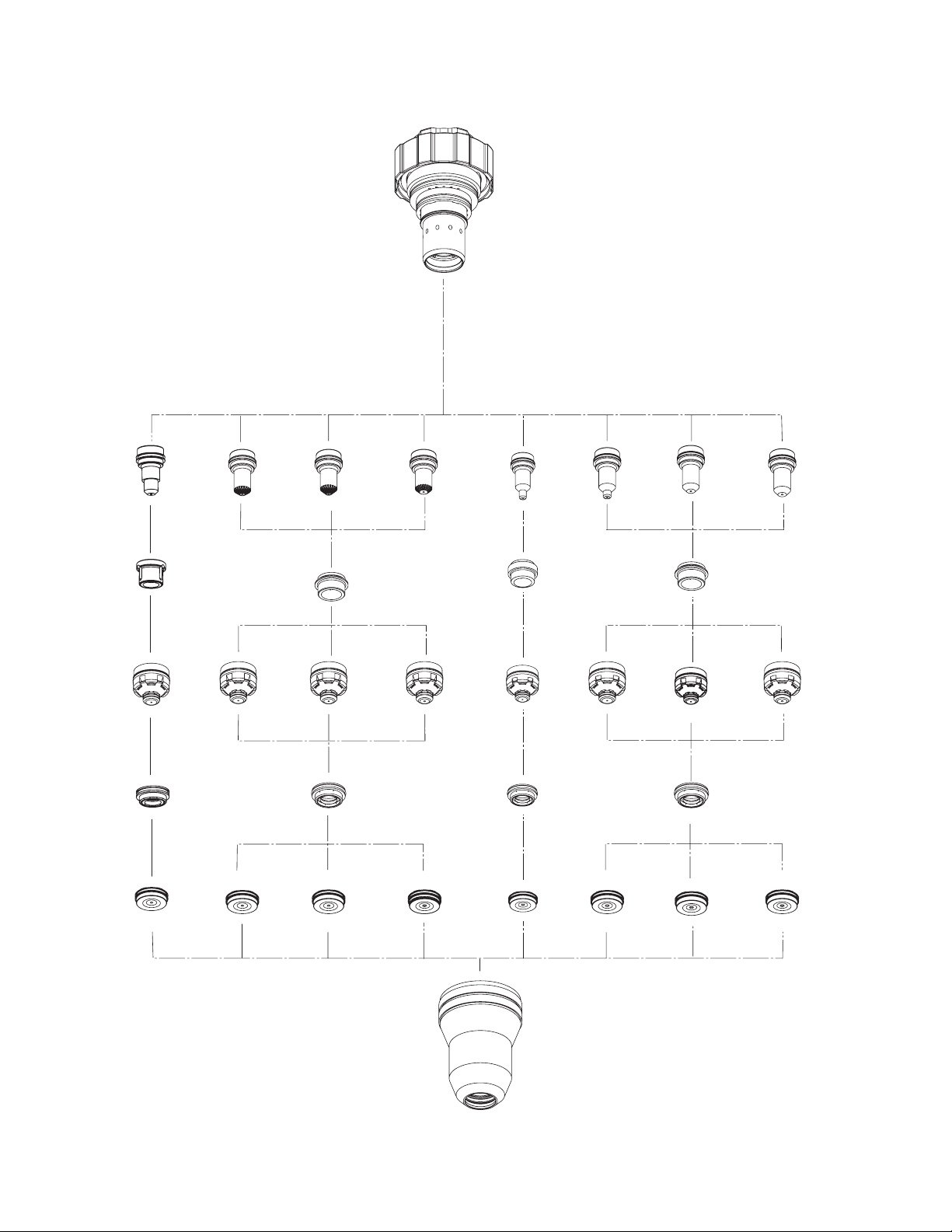
Consumables Parts Selection
21-1020
Cartridge
Art # A-04031
30A Mild Steel, Precision
Electrode, 30A MS
Plasma
50A Mild Steel, Precision
21-1068
21-1069
Electrode, 50A MS
30A MS
21-1040
Gas Distributor,
21-1050
Tip, 30A MS
Shield
30A MS
21-1082
21-1051
Tip, 50A MS
Gas Distributor,
70A Mild Steel, Precision
100A Mild Steel, Precision
21-1070
Electrode, 70A MS
Plasma
21-1041
Electrode, 100A MS
Gas Distributor
21-1052
Tip, 70A MS
Swirl
Shield
21-1272
Tip, 100A MS
Gas Distributor
21-1071
21-1053
30A Stainless Steel, Precision
Electrode, 30A SS
Plasma
50A Stainless Steel / Aluminum, Precision
21-1077
70A Stainless Steel , Precision
21-1078
Electrode, 50A SS/AL
21-1045
Gas Distributor
21-1059
Tip, 30A SS
Shield
21-1274
No Swirl
21-1060
Tip, 50A SS/AL
Gas Distributor
100A Stainless Steel / Aluminum, Precision
21-1079
Electrode, 70A SS
Plasma
21-1041
Electrode, 100A SS/AL
Gas Distributor
21-1061
Tip, 70A SS
Shield
21-1274
No Swirl
Tip, 100A SS/AL
Gas Distributor
21-1080
21-1062
21-1024
Shield Cap, 30A MS
21-1025
Shield Cap, 50A MS
21-1026
Shield Cap, 70A MS
21-1027
Shield Cap, 100A MS
21-1033
Shield Cap, 30A SS
21-1016
Shield Cup
21-1034
Shield Cap, 50A SS/AL
21-1035
Shield Cap, 70A SS
21-1036
Shield Cap, 100A SS/AL
REPLACEMENT PARTS 6-2 Manual 0-2912
Page 73

Replacement O-Rings for Consumables Parts
Shield Cap Tip Electrode
O-Ring 9-9039
O-Ring 9-9035
O-Ring 9-9061
O-Ring 9-9060
Art # A-07160
Manual 0-2912 6-3 REPLACEMENT PARTS
Page 74

This page is blank intentionally.
REPLACEMENT PARTS 6-4 Manual 0-2912
Page 75

APPENDIX 1: ALTERNATE ARC VOLTAGE SETTINGS
The Arc Voltage in the Recommended Cutting Speed Charts is based on 50 ft (15.2 m) torch lead length. For other
lead lengths refer to the application and the lead length in the following chart to set the proper Arc Voltage.
Alternate Arc Voltage Settings
for HD3070 Power Supply
Amperage
30 Amps
50 Amps
70 Amps
100 Amps
Lead Length
Feet Meter
15 4.6 - 2 v
25 7.6 - 2 v
75 22.9 + 2 v
100 30.5 + 3 v
15 4.6 - 4 v
25 7.6 - 3 v
75 22.9 + 3 v
100 30.5 + 5 v
15 4.6 - 5 v
25 7.6 - 4 v
75 22.9 + 4 v
100 30.5 + 7 v
15 4.6 - 7 v
25 7.6 - 5 v
75 22.9 + 5 v
100 30.5 + 10 v
Voltage
Adjustment
Manual 0-2912 A-1 APPENDIX
Page 76

APPENDIX 2: WIRING DIAGRAM
PIN
1
6
3
8
1
2
6
3
8
NOTE
Wiring diagram for the Oxygen Plasma Pre-Charge Unit.
3
448
1
226
PIN
RED
RED
BLACK
SHIELD
SHIELD
GREEN
3
448
1
2
6
SOCKETS
10
10115
(10)
(11)
BLUE
BLACK
10
11
SHIELD
5
12
RED
YELLOW
12
11
7
13
SHIELD
7
13
14
RED
WHITE
14
9
15
SHIELD
9
15
31
23
24
SHIELD
BLACK
YELLOW
31
23
24
23
BLACK
24
25
26
GREEN
25
26
29
SHIELD
29
32
30
36
33
SHIELD
33
34
BLACK
28
27
28
(27)
(28)
RED
BLUE
27
28
27
35
WHITE
34
35
RED
SHIELD
30
36
37
SHIELD
BROWN
32
37
11
10
40
41
43
42
23
41
43
24
27
28
ALT PLASMA RELAY
42
40
O2 PLASMA RELAY
Art # A-06471
APPENDIX A-2 Manual 0-2912
Page 77

APPENDIX 3: PATENT INFORMATION
XT-300TM Plasma Cutting Torch Patents
The following parts are covered under U.S. and Foreign Patents as follows:
Catalog # Description Patent(s)
21-1002 Torch Head U.S. Pat No(s) 6,946,616; 6,919,526; 6,852,944;
7,071,443 and 7,019,254
21-1016 Shield Cup US Pat No(s) 6946616; 6919526; 6989505
Other Pat(s) Pending
21-1020 Cartridge US Pat No(s) 6946616; 6919526; 6989505
Other Pat(s) Pending
21-1024 Shield Cap US Pat No(s) 6946616; 6919526; 6989505;
D525043; 7071443 Other Pat(s) Pending
21-1025 Shield Cap US Pat No(s) 6946616; 6919526; 6989505;
D525043; 7071443 Other Pat(s) Pending
21-1026 Shield Cap US Pat No(s) 6946616; 6919526; 6989505;
D525043; 7071443 Other Pat(s) Pending
21-1027 Shield Cap US Pat No(s) 6946616; 6919526; 6989505;
D525043; 7071443 Other Pat(s) Pending
21-1028 Shield Cap US Pat No(s) 6946616; 6919526; 6989505;
D525043; 7071443 Other Pat(s) Pending
21-1033 Shield Cap US Pat No(s) 6946616; 6919526; 6989505;
D525043; 7071443 Other Pat(s) Pending
21-1034 Shield Cap US Pat No(s) 6946616; 6919526; 6989505;
D525043; 7071443 Other Pat(s) Pending
21-1035 Shield Cap US Pat No(s) 6946616; 6919526; 6989505;
D525043; 7071443 Other Pat(s) Pending
21-1036 Shield Cap US Pat No(s) 6946616; 6919526; 6989505;
D525043; 7071443 Other Pat(s) Pending
21-1040 Plasma Gas Distributor US Pat No(s) 6946616; 6919526; 6989505
Other Pat(s) Pending
21-1041 Plasma Gas Distributor US Pat No(s) 6946616; 6919526; 6989505
Other Pat(s) Pending
21-1045 Plasma Gas Distributor US Pat No(s) 6946616; 6919526; 6989505
Other Pat(s) Pending
21-1050 Tip US Pat No(s) 6946616; 6919526; 6989505;
7005600; D519135; D524,336 Other Pat(s) Pending
21-1051 Tip US Pat No(s) 6946616; 6919526; 6989505;
7005600; D519135; D524,336 Other Pat(s) Pending
21-1052 Tip US Pat No(s) 6946616; 6919526; 6989505;
7005600; D519135; D524,336 Other Pat(s) Pending
21-1053 Tip US Pat No(s) 6946616; 6919526; 6989505;
7005600; D519135; D524,336 Other Pat(s) Pending
21-1054 Tip US Pat No(s) 6946616; 6919526; 6989505;
7005600; D519135; D524,336 Other Pat(s) Pending
21-1059 Tip US Pat No(s) 6946616; 6919526; 6989505; 7005600;
D519135; D524,336 Other Pat(s) Pending
21-1060 Tip US Pat No(s) 6946616; 6919526; 6989505; 7005600;
D519135; D524,336 Other Pat(s) Pending
21-1061 Tip US Pat No(s) 6946616; 6919526; 6989505; 7005600;
D519135; D524,336 Other Pat(s) Pending
21-1062 Tip US Pat No(s) 6946616; 6919526; 6989505; 7005600;
D519135; D524,336 Other Pat(s) Pending
21-1068 Electrode US Pat No(s) 6946616; 6919526; 6989505; 6998566;
D517577 Other Pat(s) Pending
Manual 0-2912 A-3 APPENDIX
Page 78

XT-300TM Plasma Cutting Torch Patents Continued
The following parts are covered under U.S. and Foreign Patents as follows:
Catalog # Description Patent(s)
21-1069 Electrode US Pat No(s) 6946616; 6919526; 6989505; 6998566
Other Pat(s) Pending
21-1070 Electrode US Pat No(s) 6946616; 6919526; 6989505; 6998566;
D517576 Other Pat(s) Pending
21-1071 Electrode US Pat No(s) 6946616; 6919526; 6989505; 6998566;
D517576 Other Pat(s) Pending
21-1072 Electrode US Pat No(s) 6946616; 6919526; 6989505; 6998566;
D517576 Other Pat(s) Pending
21-1077 Electrode US Pat No(s) 6946616; 6919526; 6989505; 6998566
Other Pat(s) Pending
21-1078 Electrode US Pat No(s) 6946616; 6919526; D505963; 6989505;
6998566 Other Pat(s) Pending
21-1079 Electrode US Pat No(s) 6946616; 6919526; 6989505; 6998566
Other Pat(s) Pending
21-1080 Electrode US Pat No(s) 6946616; 6919526; 6989505; 6998566;
D517577 Other Pat(s) Pending
21-1082 Shield Gas Distributor US Pat No(s) 6946616; 6919526; 6989505
Other Pat(s) Pending
21-1272 Shield Gas Distributor US Pat No(s) 6946616; 6919526; 6989505
Other Pat(s) Pending
21-1273 Shield Gas Distributor US Pat No(s) 6946616; 6919526; 6989505
Other Pat(s) Pending
21-1274 Shield Gas Distributor US Pat No(s) 6946616; 6919526; 6989505
Other Pat(s) Pending
21-1275 Shield Cap US Pat No(s) 6946616; 6919526; 6989505; D523042;
7071443 Other Pat(s) Pending
The following parts are also licensed under U.S. Patent No. 5,120,930 and 5,132,512:
Catalog Number Description
21-1027 Shield Cap
21-1275 Shield Cap
NOTE
This manual may refer to some or all of the parts listed.
APPENDIX A-4 Manual 0-2912
Page 79

Global Customer Service Contact Information
Thermadyne USA
2800 Airport Road
Denton, Tx 76207 USA
Telephone: (940) 566-2000
800-426-1888
Fax: 800-535-0557
Email: sales@thermalarc.com
Thermadyne Victor Brasil
Avenida Brasil
13629-Cordovil
Rio de Janeiro, Brazil 21012-351
Telephone: 55-21-2485-8998
Fax: 55-21-2-485-8735
Thermadyne Canada
2070 Wyecroft Road
Oakville, Ontario
Canada, L6L5V6
Telephone: (905)-827-1111
Fax: 905-827-3648
Thermadyne Asia Sdn Bhd
Lot 151, Jalan Industri 3/5A
Rawang Integrated Industrial Park - Jln Batu Arang
48000 Rawang Selangor Darul Ehsan
West Malaysia
Telephone: 603+ 6092 2988
Fax : 603+ 6092 1085
Cigweld, Australia
71 Gower Street
Preston, Victoria
Australia, 3072
Telephone: 61-3-9474-7400
Fax: 61-3-9474-7510
Thermadyne Italy
OCIM, S.r.L.
Via Benaco, 3
20098 S. Giuliano
Milan, Italy
Tel: (39) 02-98 80320
Fax: (39) 02-98 281773
Thermadyne Chile
Piloto Lazo #90
Cerrillos
Santiago, Chile 7278-654
Telephone: 56-2-557-2465
Fax: 56-2-557-5349
Thermadyne Europe
Europe Building
Chorley North Industrial Park
Chorley, Lancashire
England, PR6 7Bx
Telephone: 44-1257-261755
Fax: 44-1257-224800
Thermadyne, China
RM 102A
685 Ding Xi Rd
Chang Ning District
Shanghai, PR, 200052
Telephone: 86-21-69171135
Fax: 86-21-69171139
Thermadyne South Africa
209 Risi Ave.
Linmeyer
Johannesberg, 2197
South Africa
Tel: (27) 11-917 3600
Fax: (27) 11-917 8580
Thermadyne International
2070 Wyecroft Road
Oakville, Ontario
Canada, L6L5V6
Telephone: (905)-827-9777
Fax: 905-827-9797
Page 80

Corporate Headquarters
16052 Swingley Ridge Road
Suite 300
St. Louis, MO 63017
Telephone: 636-728-3000
Email: TDCSales@Thermadyne.com
www.thermadyne.com
 Loading...