

Page 1

8.0 TORCH OPERATION
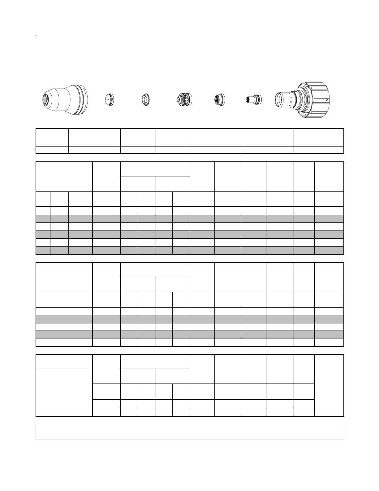
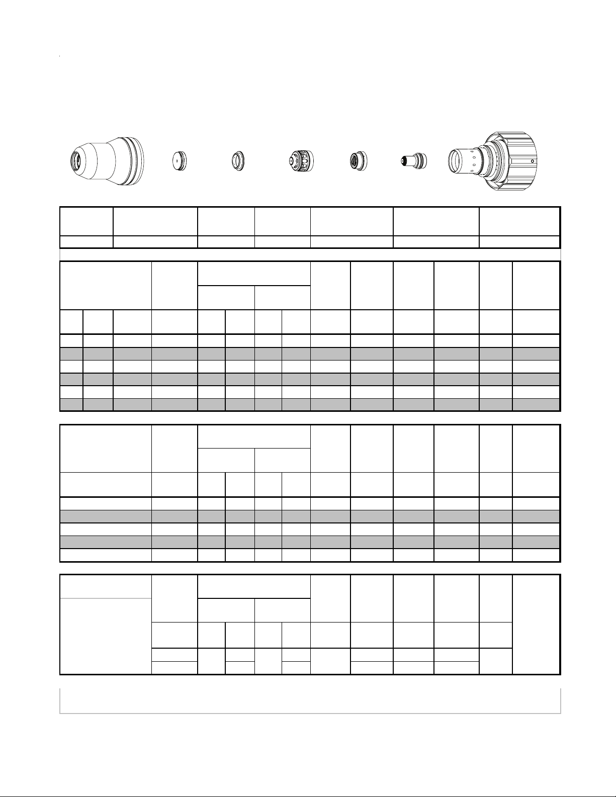
Torch Parts Selection
The application will determine which torch parts must be used. Refer to the cut charts for the proper torch parts to
install for a selected application.
CAUTION
Do not interchange parts. Make sure all torch parts correspond with the plasma and shield
gases in use for the application.
Pre-Setting Power Supply Controls
Set the Power Supply controls prior to operating the system as described in the power supply Operating Manual.
Refer to the cutting charts for the proper cutting parameters for the application.
Recommended Cutting Speeds
Cutting speed depends on material and thickness. The following factors may affect system performance:
• Torch parts wear; gas quality and mass flow / pressure; operator experience; torch standoff height; proper
work cable connection; alloy content of material; cutting table capabilities & accuracy.
NOTE
This information represents realistic expectations using recommended practices and wellmaintained systems. Actual speeds may vary from those shown in the charts depending on
the alloy content of the selected material. Voltage ratings may vary depending on the CNC,
cutting table, or height controller.
For complete cutting speed chart data refer to the following pages.
Consumables Notes
Always assemble the consumable parts properly. Improper assembly may damage the parts or the torch head.
Ensure that parts are seated together correctly.
Always check the shield gas distributor for charring when changing parts. Do not use the distributor if it is charred.
Replace the shield gas distributor regularly to ensure proper performance.
Operational Notes
Always purge the torch after changing consumables or if the power supply has been shut off. The power supply's
built-in purge function may not be enough to properly purge the torch. Manually flow gas with the 'Test Cut Flow' and
'Test Pre-Flow' functions to help remove any remaining coolant from the lines.
Slightly increasing the preflow pressure may increase piercing ability on thicker materials. However, increasing the
preflow pressure too much may affect plasma starting reliability (misfiring).
Decreasing preflow pressure may improve piloting. Preflow pressure can be reduced without affecting cut performance as long as the pilot arc still transfers to the plate well. Decreasing preflow pressure too much will affect the
ability to transfer the arc to the plate and cause damage to the tip.
Notes on Chart Measurements
Pressure measurements in the charts are in psi(g), not psi(a). 0 psi(g) = 14.7 psi(a) (1 atmosphere).
Ball settings are at the center of the gauge ball.
Manual 0-4829 Rev AN 8-3 TORCH DATA for Ultra-Cut
Page 2
Ohmic Sensing
Ohmic sensing is not recommended with water shield. Water on the plate interferes electrically with the ohmic
sensing circuit.
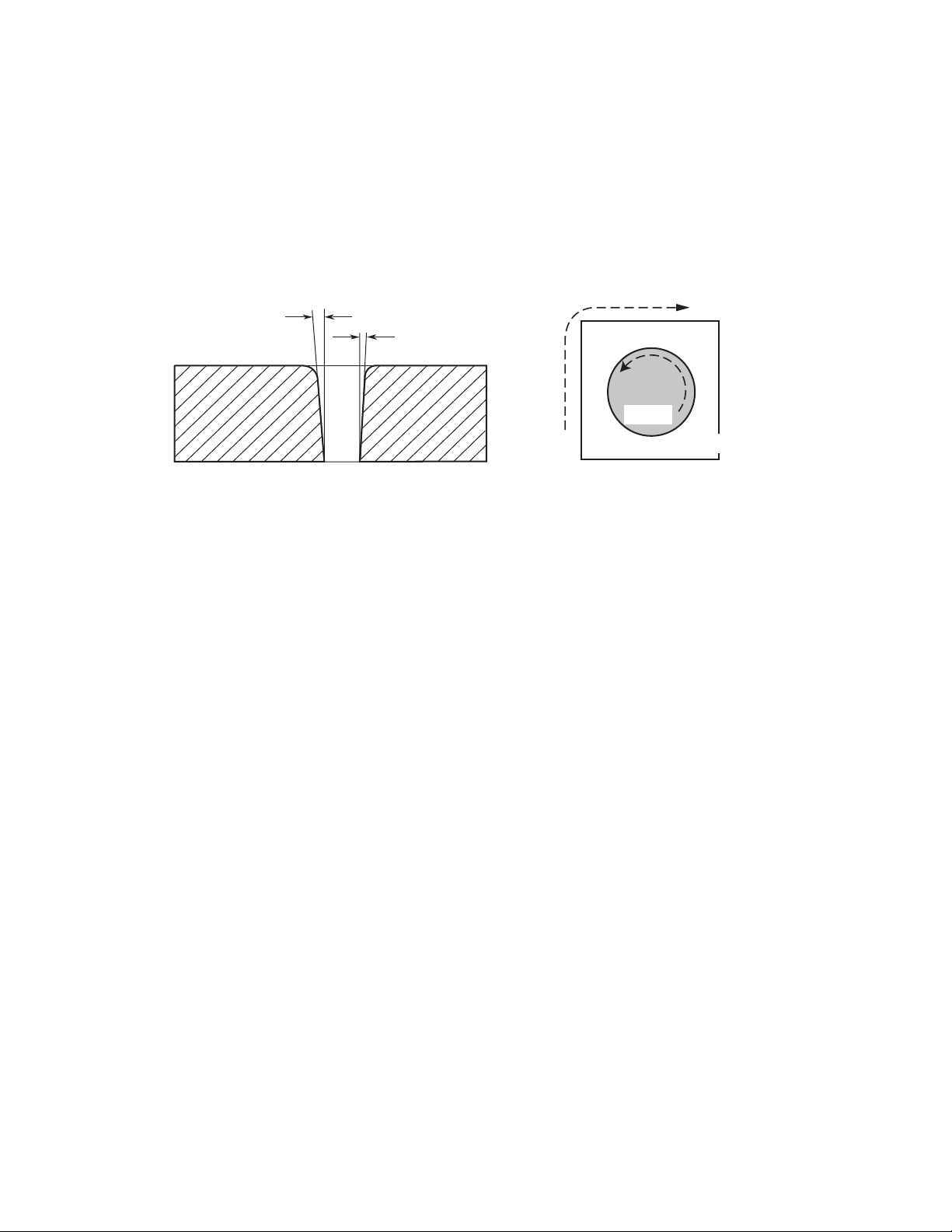
Direction of Cut
The plasma gas stream swirls as it leaves the torch to maintain a stable arc column. This swirl effect results in one
side of a cut being more square than the other. Viewed along the direction of travel, the right side of the cut is more
square than the left.
Left Side
Cut Angle
Right Side
Cut Angle
A-00512
Clockwise
Scrap
Counter-
Clockwise
Scrap
Workpiece
Art # A-04182
Side Characteristics Of Cut
To make a square - edged cut along an inside diameter of a circle, move the torch counterclockwise around the circle.
To keep the square edge along an outside diameter cut, move the torch in a clockwise direction.
Underwater Cutting
Cutting on a water table either underwater or with the water touching the plate or with a water muffler system is not
recommended. If a water table is used the water level must be a minimum of 4 inches / 100 mm from the bottom of the
plate. Failure to follow this recommendation could result in poor cut quality and short consumable parts life.
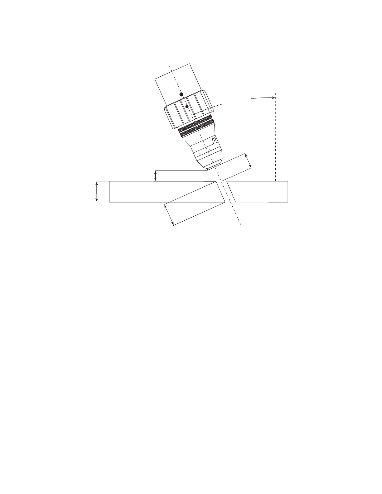
Bevel Cutting Definitions
Bevel Angle The angle between the center line of the torch and a line that is perpendicular to the workpiece.
If the torch is perpendicular to the workpiece, the Bevel Angle is zero. The maximum Bevel
Angle is 45°.
Nominal Thickness The vertical thickness of the workpiece.
Effective Thickness The length of the cut edge, or the distance the arc travels through the material while cutting.
Effective Thickness is equal to the nominal thickness divided by the cosine of the bevel
angle. Effective Thicknesses are listed in the cut chart.
Clearance The vertical distance from the lowest point of the torch to the surface of the workpiece.
Effective Cut Height The linear distance from the center of the torch outlet to the workpiece surface along the
torch center-line. A range of Effective Cut Height distances are listed in the cut chart. The
smallest number is for a straight cut (bevel angle = 0°). The largest number is for a 45° bevel
cut with a clearance of 2 mm (0.125 in).
Arc Voltage The Arc Voltage setting is dependent on the Bevel Angle and the setup of the cutting system.
The Arc Voltage setting on one system may be different from a second system even if the
workpiece is the same thickness. The arc voltages for bevel cutting are not supplied in the
bevel cut charts.
TORCH DATA for Ultra-Cut 8-4 Manual 0-4829 Rev AN
Page 3
Clearance
To rch
Center-line
0°
Bevel Angle
Effective Cut
Height
Nominal
Thickness
Work Piece
Effective
Thickness
Art # A-08568
Manual 0-4829 Rev AN 8-5 TORCH DATA for Ultra-Cut
Page 4

TORCH DATA for Ultra-Cut 8-6 Manual 0-4829 Rev AN
Page 5

Insert "Up To 100 Amp
Standard Cutting" Tab.
Discard this sheet.
Manual 0-4829 Rev AN 8-7 TORCH DATA for Ultra-Cut
TAB SHEET
Page 6

This Page Intentionally Blank
TORCH DATA for Ultra-Cut 8-8 Manual 0-4829 Rev AN
Page 7
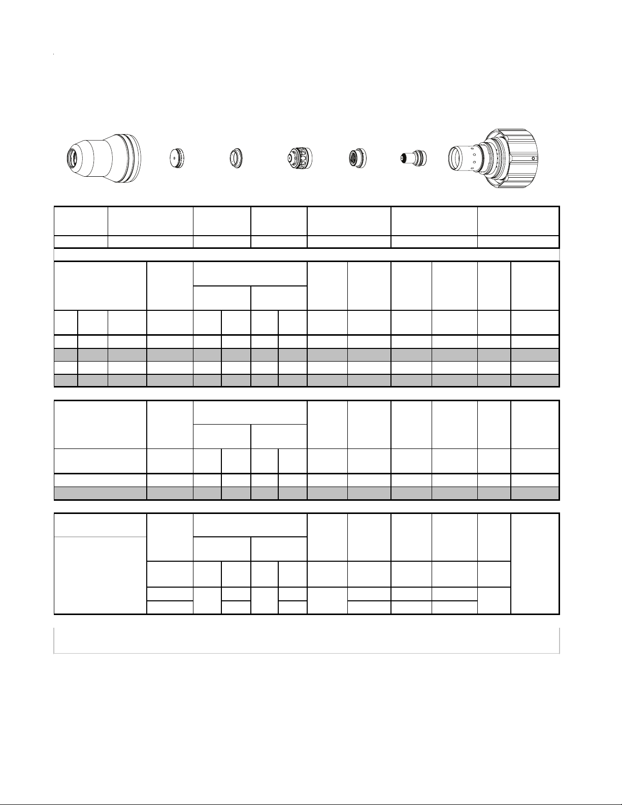
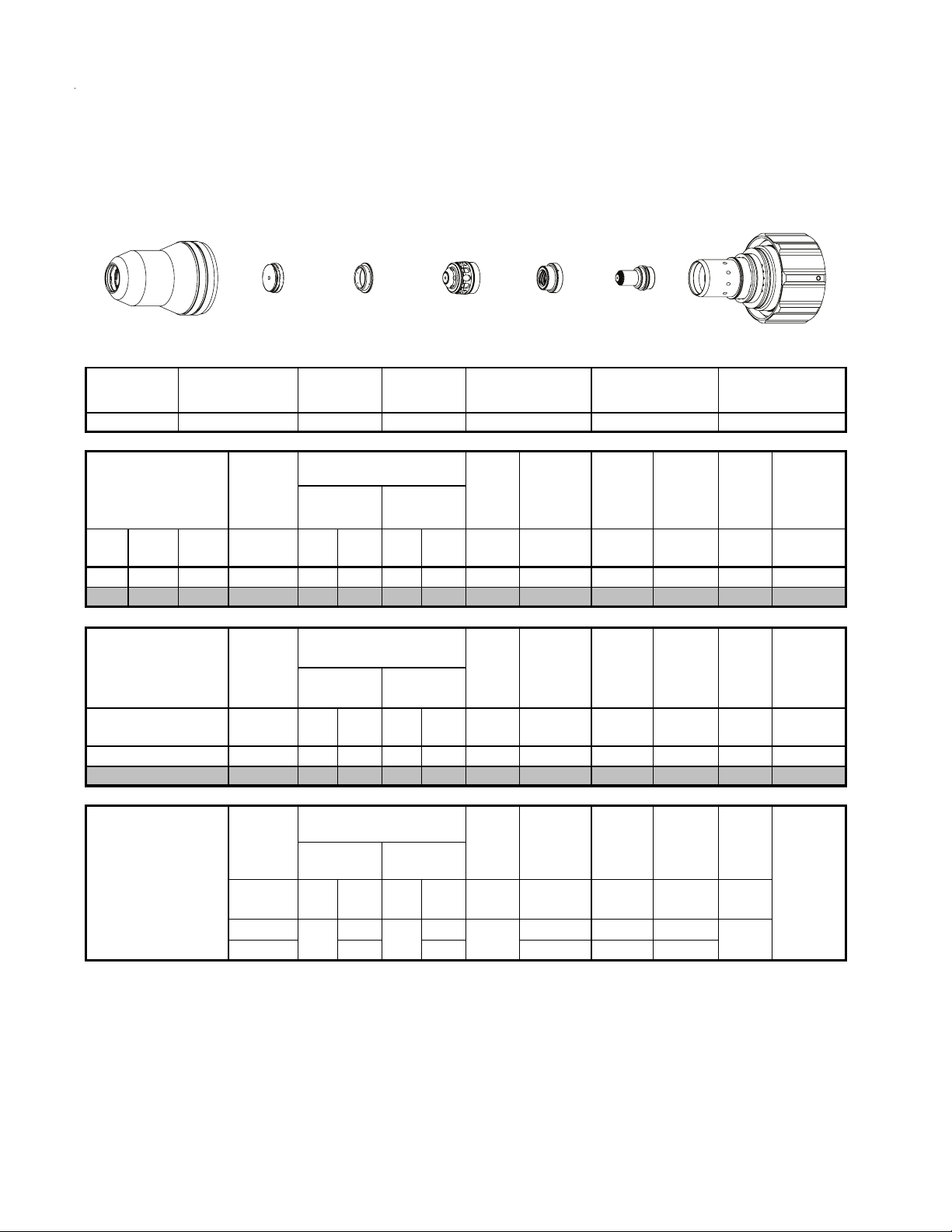
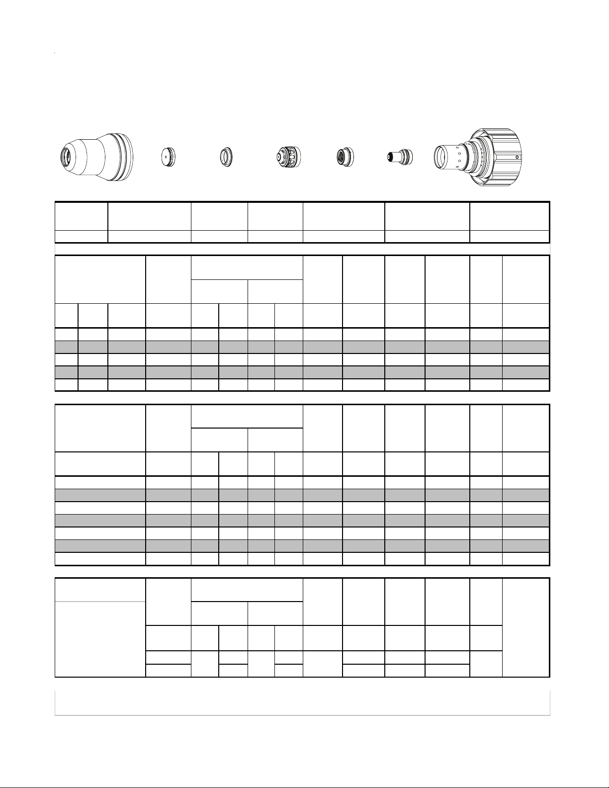
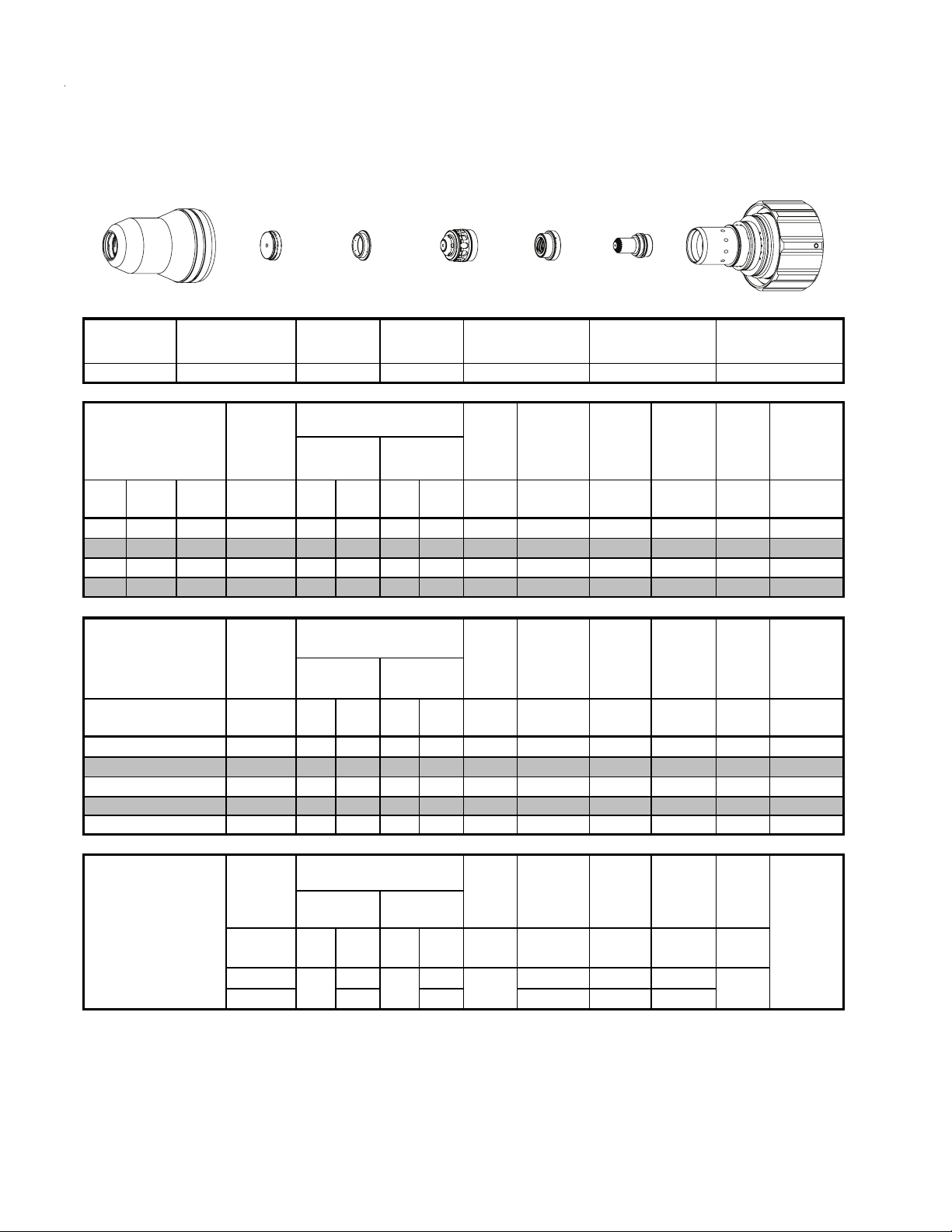
8.01 Standard Cutting Up To 100 Amp
Mild Steel
30A
Plasma / O2 Shield
O
2
Shield Cup
Shield Cap
Shield Gas
Distributor
Tip
This Art Is For Reference ONLY
Shield Cup Shield Cap
Mate ri al
Thickn es s
(ga) (in) inch (PSI) (Ball) (PSI) (Ball) (PSI) Volts
20 0.036 60 22 120 21 120 128 0.050 130 0.120 0.2 0.058
16 0.060 60 22 120 21 120 143 0.050 60 0.120 0.3 0.070
14 0.075 60 22 120 21 120 145 0.070 45 0.120 0.3 0.072
12 0.105 60 22 120 21 120 148 0.110 40 0.150 0.3 0.074
10 0.135 80 22 120 21 120 154 0.130 30 0.150 0.3 0.085
3/16 0.188 80 22 120 21 120 154 0.120 25 0.150 0.4 0.075
Pre Flow
Pressure
(Air)
Shield Gas
Distributor
Cut Flow Rate s /
Pressures
2
Tip
) Shield (Air)
Plasma Gas
Distributor
Plasma Gas
Distributor
22-1040 22-1068 22-102022-1016 22-1024 22-1082 22-1050
Arc
Vol tag e
Torch
Working
Height
(in)
±0.005
Electrode
Cartridge
Art # A-07958_AB
Electrode Cartridge
Travel
Speed
(ipm ) (in) (s ec) (in)
Initial
Piercing
Height
Pierce
Delay
Kerf Width
@ Rec.
SpeedPlas m a (O
Mate ri al
Thickn es s
(mm)
1
2
3
4
5
16A Arc Cur r e nt
Burn-through
may occur
for th ickn es s es
< 1/16" (0.063") / 1.6
mm.
BOLD TYPE
indicates maximum piercing parameters.
Pre Flow
Pressure
(Air)
(Bar) (Ball) (Bar) (Ball) (Bar) Volts
4.1 22 8.3 21 8.3 130 1.3 3050 3.0 0.2 1.5
4.1 22 8.3 21 8.3 145 1.9 1130 3.1 0.3 1.8
4.1 22 8.3 21 8.3 150 3.0 910 3.8 0.3 2.0
5.5 22 8.3 21 8.3 154 3.2 710 3.8 0.3 2.1
5.5 22 8.3 21 8.3 155 3.0 640 3.8 0.4 1.9
Pre Flow
Pressure
)
(N
2
(PSI) /
(Bar)
20 40 80 0.100 300 0.100
1.4 2.8 5.5 2.5 7600 2.5
Cut Flow Rate s /
Pressures Arc
Plas m a (O
Plas m a (N
(Ball)
20 70 148
) Shield (Air)
2
Cut Flow Rate s /
Pressures Arc
) Shield (N2)
2
(PSI) /
(Bar)
(Ball)
(PSI) /
BOLD ITALIC
Vol tag e
Marking
Vol tag e
(Bar)
Torch
Working
Height
(mm)
±0.1
Torch
Working
Height
Vol ts
in ±0.005 /
mm ±0. 1
indicates edge starts only.
( mm/mi n)
Travel
Speed
Travel
Speed
ipm /
mm/min
Initial
Piercing
Height
(mm ) (sec) (m m )
Initial
Tran s fer
Height
in ±0.005 /
mm ±0.1
Pierce
Delay
Pierce
Delay
(sec)
0
Kerf Width
@ Rec.
Speed
Mar ki ng
quality
degrades
as
thi ckn es s
decreases
Manual 0-4829 Rev AN 8-9 TORCH DATA for Ultra-Cut
Page 8

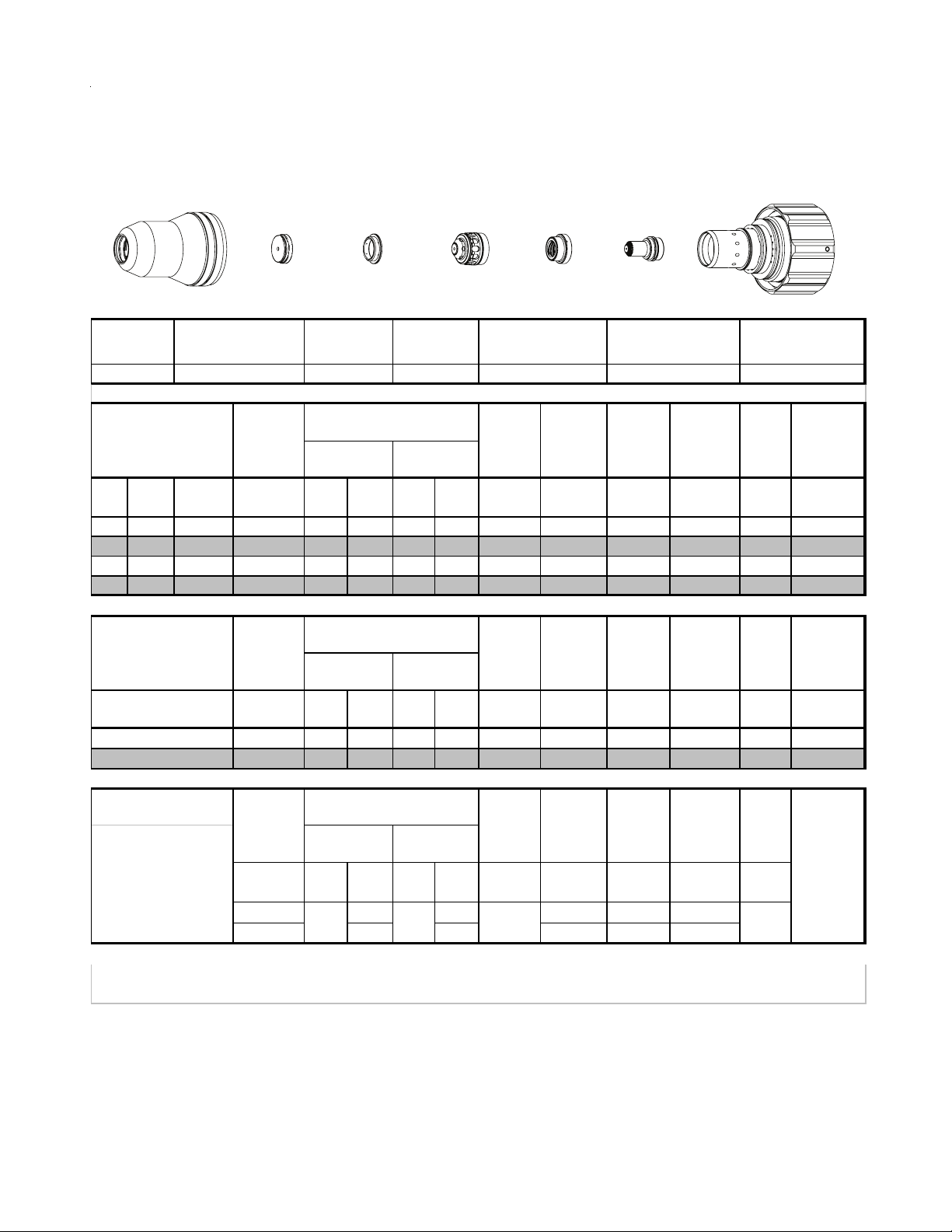
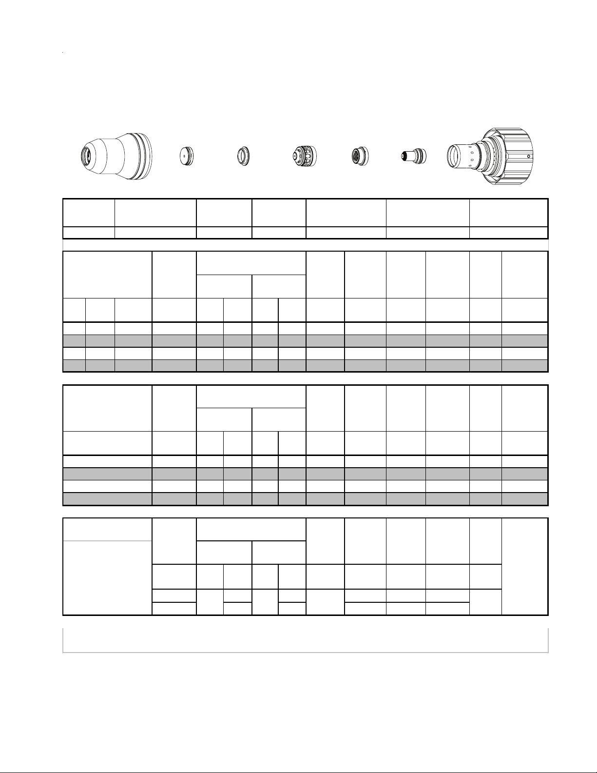
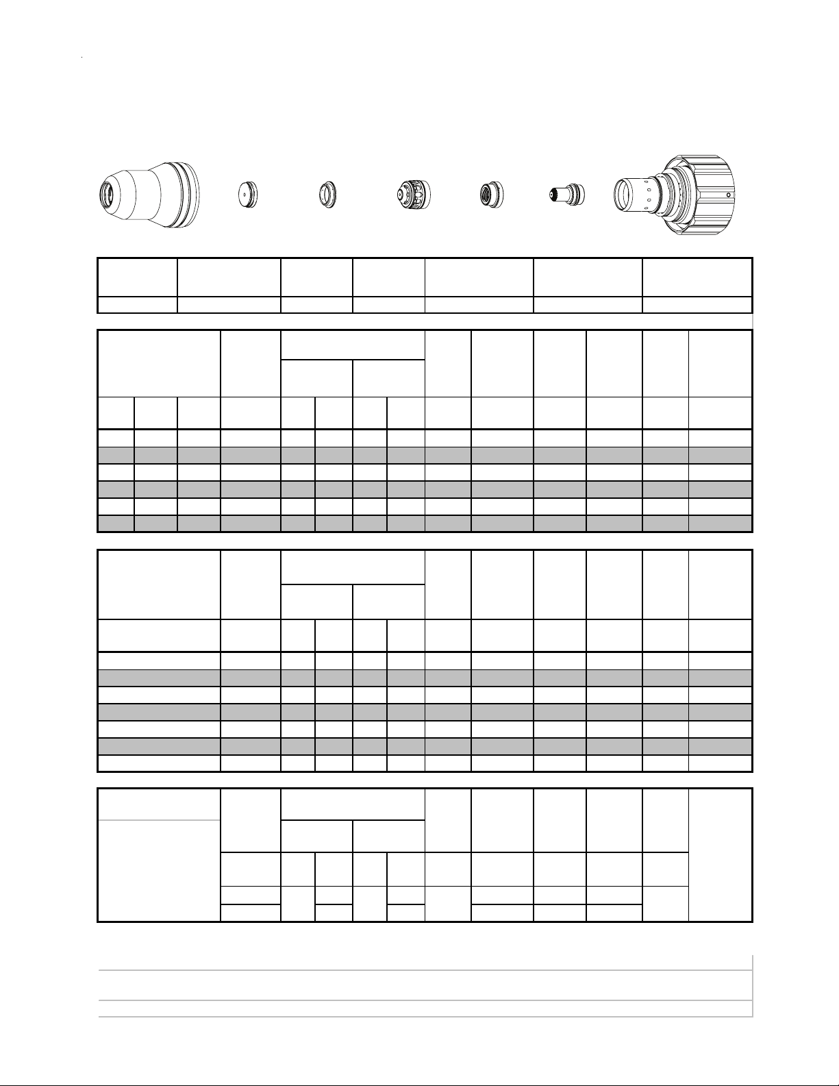
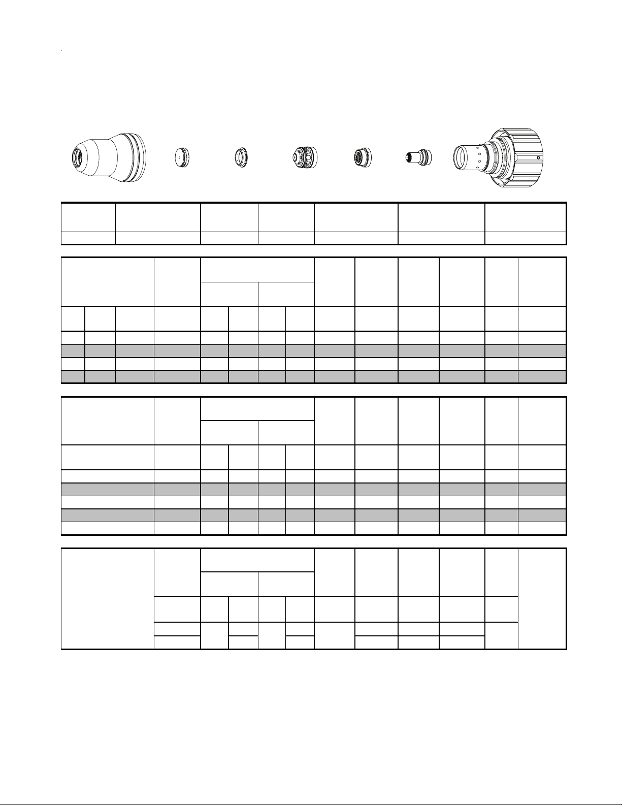
Stainless Steel
30A
Air Plasma / Air Shield
Shield Cup
Shield Cap
Shield Gas
Distributor
Tip
This Art Is For Reference ONLY
Shield Cup Shield Cap
Mate ri al
Thickn es s
(ga) (in) inch (PSI) (Ball) (PSI) (Ball) (PSI) Volts
26 0.019 60 64 120 20 120 87 0.020 350 0.040 0.0 0.029
24 0.025 60 64 120 20 120 85 0.020 320 0.040 0.0 0.028
22 0.031 60 64 120 20 120 80 0.020 310 0.040 0.0 0.034
20 0.038 60 64 120 20 120 75 0.020 300 0.060 0.1 0.025
18 0.050 60 64 120 20 120 78 0.020 150 0.080 0.2 0.032
16 0.063 60 64 120 20 120 76 0.020 110 0.080 0.2 0.030
Pre Flow
Pressure
(Air)
Shield Gas
Distributor
Cut Flow Rate s /
Pressures
Tip
Plasma Gas
Distributor
Plasma Gas
Distributor
22-1045 22-1077 22-102022-1016 22-1033 22-1274 22-1059
Arc
Vol tag e
Torch
Working
Height
(in)
±0.005
Electrode
Cartridge
Art # A-07958_AB
Electrode Cartridge
Travel
Speed
(ipm ) (in) (s ec) (in)
Initial
Piercing
Height
Pierce
Delay
Kerf Width
@ Rec.
SpeedPlas m a (Air) Shield (Air)
Mate ri al
Thickn es s
(mm)
0.6
0.8
1.0
1.5
2
16A Arc Cur r e nt
Burn-through
may occur
for th ickn es s es
< 1/16" (0.063") / 1.6
mm.
BOLD TYPE
indicates maximum piercing parameters.
Pre Flow
Pressure
(Air)
(Bar) (Ball) (Bar) (Ball) (Bar) Volts
4.1 64.0 8.3 20.0 8.3 85.0 0.5 8300.0 1.0 0.0 0.7
4.1 64.0 8.3 20.0 8.3 80.0 0.5 7860.0 1.1 0.0 0.9
4.1 64.0 8.3 20.0 8.3 75.0 0.5 7190.0 1.6 0.1 0.7
4.1 64.0 8.3 20.0 8.3 77.0 0.5 3100.0 2.0 0.2 0.8
4.1 64.0 8.3 20.0 8.3 74.0 0.5 2600.0 2.0 0.2 0.7
Pre Flow
Pressure
)
(N
2
(PSI) /
(Bar)
20 40 80 0.100 300 0.100
1.4 2.8 5.5 2.5 7600 2.5
Cut Flow Rate s /
Pressures Arc
Marking
(Bar)
Vol tag e
Vol tag e
Vol ts
Plas m a (Air) Shield (Air)
Cut Flow Rate s /
Pressures Arc
Plas m a (N
(Ball)
20 70 93 0
) Shield (N2)
2
(PSI) /
(Bar)
(Ball)
(PSI) /
BOLD ITALIC
Torch
Working
Height
(mm)
±0.1
Torch
Working
Height
in ±0.005 /
mm ±0. 1
indicates edge starts only.
Travel
Speed
( mm/mi n)
Travel
Speed
ipm /
mm/min
Initial
Piercing
Height
(mm) (sec) (mm)
Initial
Tran s fer
Height
in ±0.005 /
mm ±0.1
Pierce
Delay
Pierce
Delay
(sec)
Kerf Width
@ Rec.
Speed
Mar ki ng
quality
degrades
as
thi ckn es s
decreases
TORCH DATA for Ultra-Cut 8-10 Manual 0-4829 Rev AN
Page 9
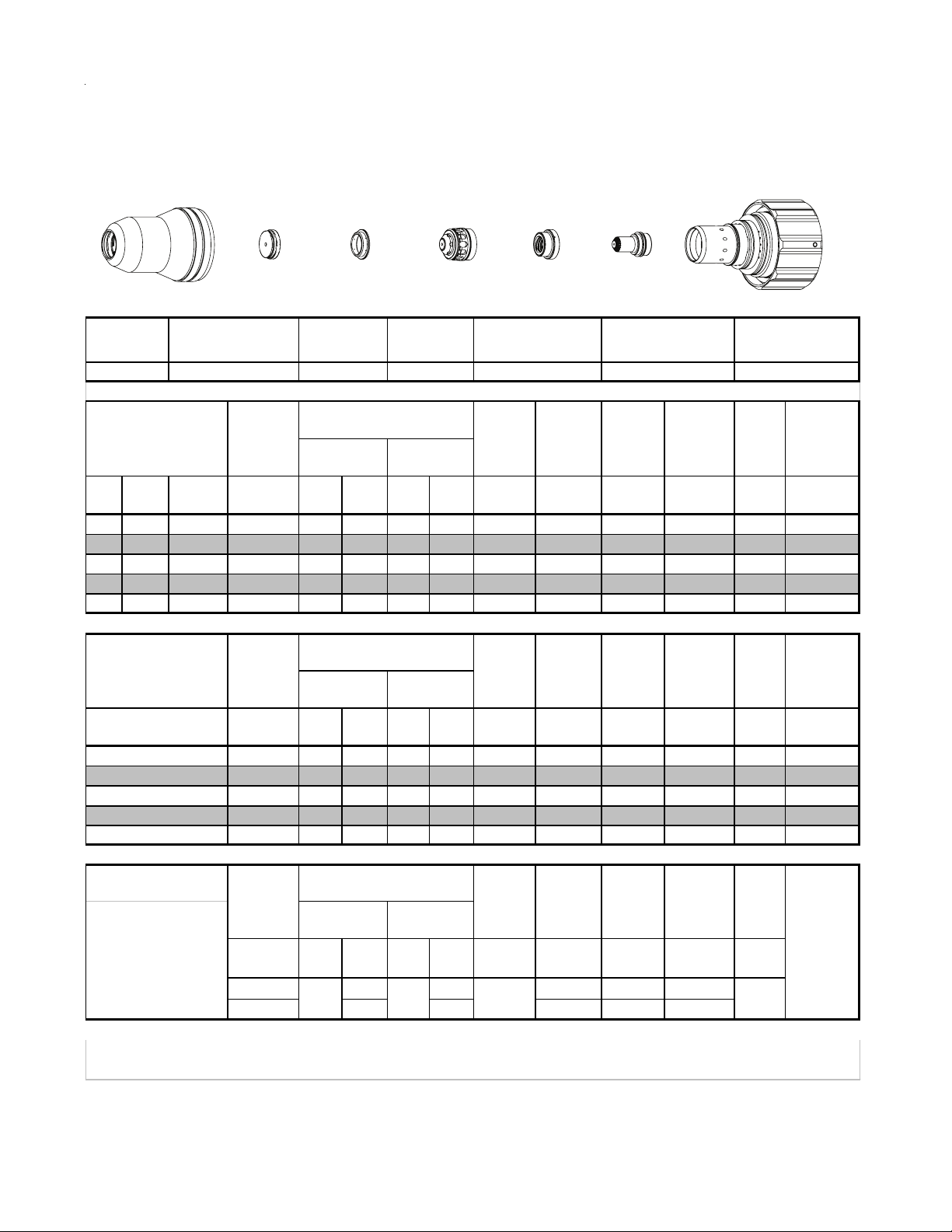
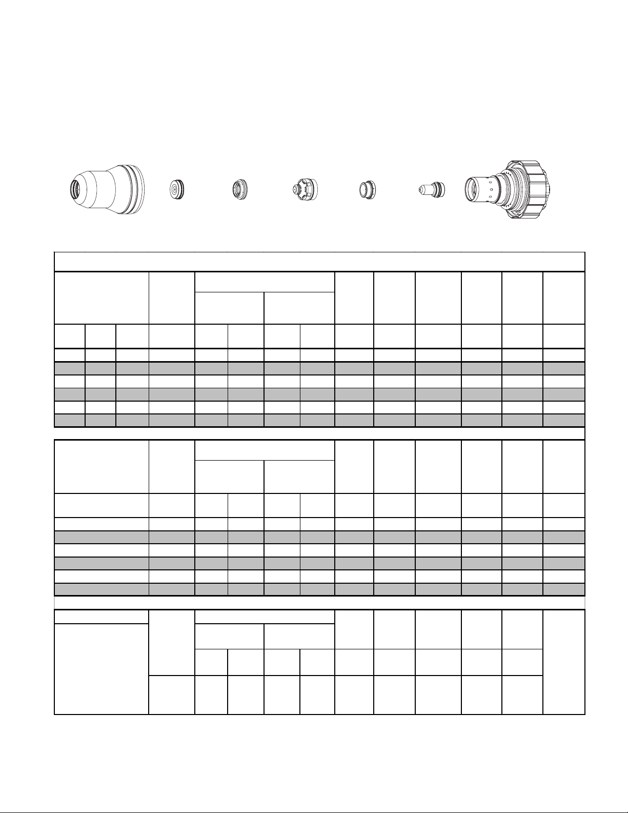
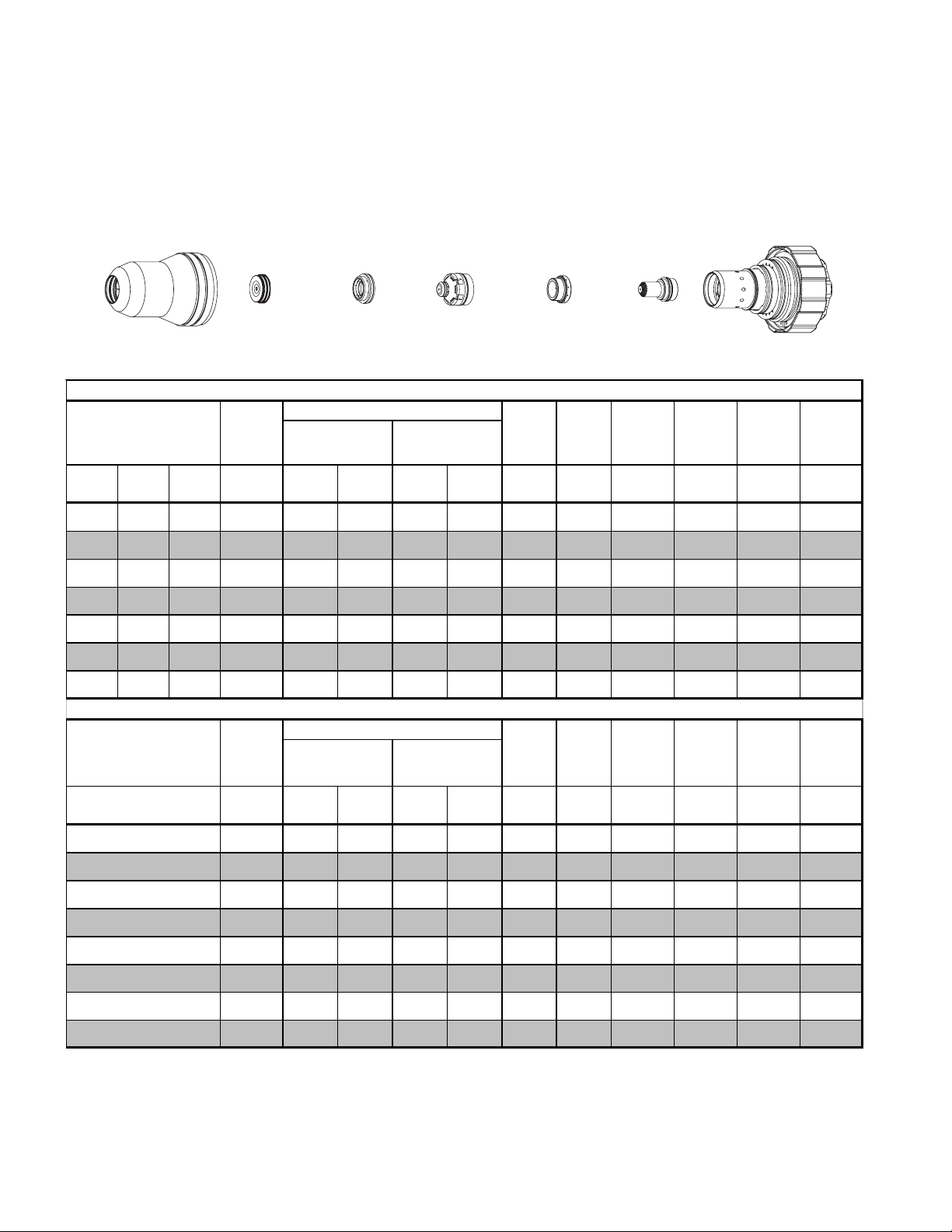
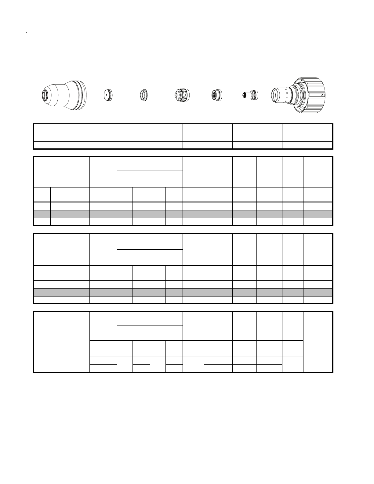
Stainless Steel
30A
Plasma / H2O Shield
N
2
Shield Cup
Shield Cap
Shield Gas
Distributor
Tip
This Art Is For Reference ONLY
)
2
Shield Gas
Distributor
Cut Flow Rate s /
Pressures
2
Tip
) Shield (H2O)
Shield Cup Shield Cap
Mate ri al
Thickn es s
(ga) (in) inch (PSI) (Ball) (PSI) (Ball) (PSI) Volts
26 0.019 90 75 120 4 55 91 0.020 600 0.040 0.0 0.047
24 0.025 90 64 120 4 55 97 0.020 440 0.040 0.0 0.045
22 0.031 90 50 120 4 55 95 0.020 420 0.040 0.0 0.045
20 0.038 90 60 120 5 55 105 0.020 300 0.050 0.1 0.044
18 0.050 90 60 120 5 55 78 0.030 250 0.050 0.1 0.035
16 0.063 90 60 120 5 55 85 0.050 205 0.060 0.2 0.044
Pre Flow
Pressure
(N
Plasma Gas
Distributor
Plasma Gas
Distributor
22-1045 22-1077 22-102022-1016 22-1033 22-1274 22-1059
Arc
Vol tag e
Torch
Working
Height
(in)
±0.005
Electrode
Cartridge
Art # A-07958_AB
Electrode Cartridge
Travel
Speed
(ipm ) (in) (s ec) (in)
Initial
Piercing
Height
Pierce
Delay
Kerf Width
@ Rec.
SpeedPlas m a (N
Mate ri al
Thickn es s
(mm)
0.6
0.8
1.0
1.5
2.0
16A Arc Cur r e nt
Burn-through
may occur
for th ickn es s es
< 1/16" (0.063") / 1.6
mm.
BOLD TYPE
indicates maximum piercing parameters.
Pre Flow
Pressure
(N
)
2
(Bar) (Ball) (Bar) (Ball) (Bar) Volts
6.2 75 8.3 4 3.8 96 0.5 12110 1.0 0.0 1.2
6.2 64 8.3 4 3.8 96 0.5 10450 1.0 0.0 1.1
6.2 50 8.3 4 3.8 102 0.5 7470 1.3 0.1 1.1
6.2 60 8.3 5 3.8 83 1.0 5550 1.4 0.2 1.0
6.2 60 8.3 5 3.8 93 2.0 3820 1.8 0.3 1.4
Pre Flow
Pressure
(N
)
2
(PSI) /
(Bar)
20 40 80 0.100 300 0.100
1.4 2.8 5.5 2.5 7600 2.5
Cut Flow Rate s /
Pressures Arc
Plas m a (N
Plas m a (N
(Ball)
20 70 93
) Shield (H2O)
2
Cut Flow Rate s /
Pressures Arc
) Shield (N2)
2
(Ball)
(PSI) /
BOLD ITALIC
(PSI) /
(Bar)
Vol tag e
Marking
Vol tag e
(Bar)
Torch
Working
Height
(mm)
±0.1
Torch
Working
Height
Vol ts
in ±0.005 /
mm ±0. 1
indicates edge starts only.
Speed
( mm/mi n)
Speed
Travel
Travel
ipm /
mm/min
Initial
Piercing
Height
(mm) (sec) (mm)
Initial
Tran s fer
Height
in ±0.005 /
mm ±0.1
Pierce
Delay
Pierce
Delay
(sec)
0
Kerf Width
@ Rec.
Speed
Mar ki ng
quality
degrades
as
thi ckn es s
decreases
Manual 0-4829 Rev AN 8-11 TORCH DATA for Ultra-Cut
Page 10
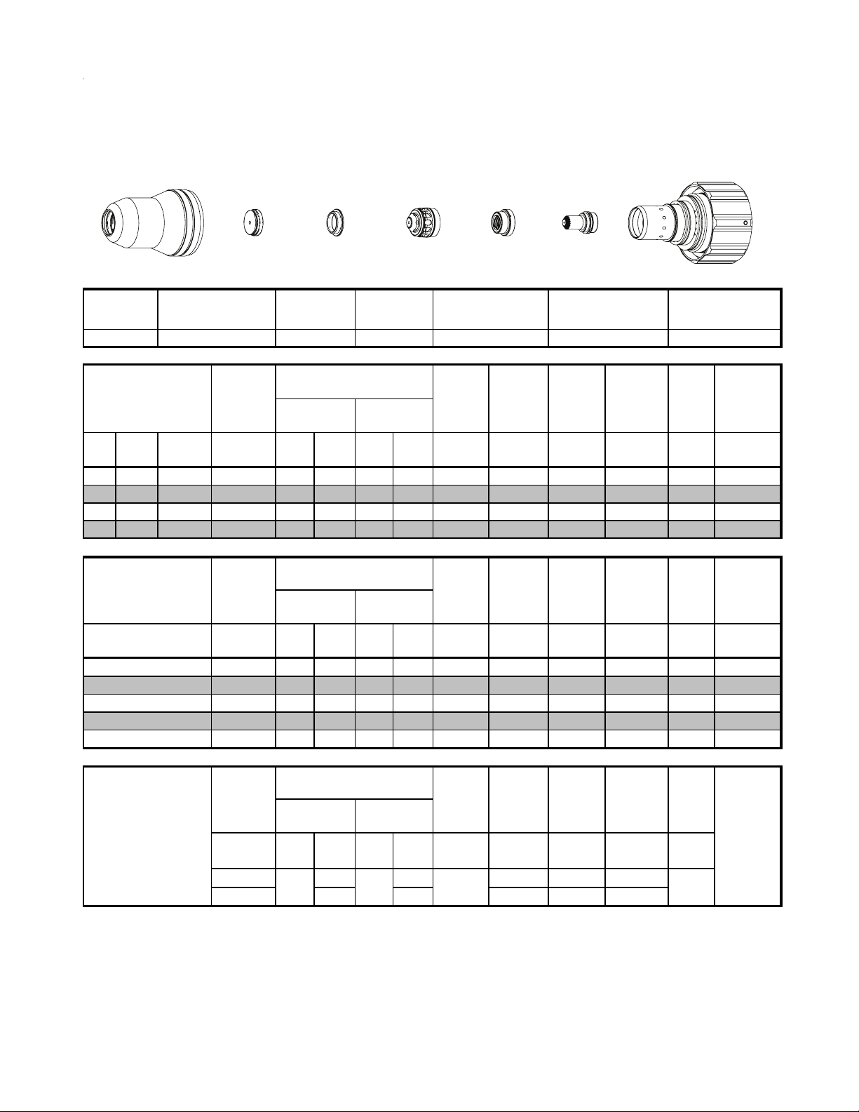
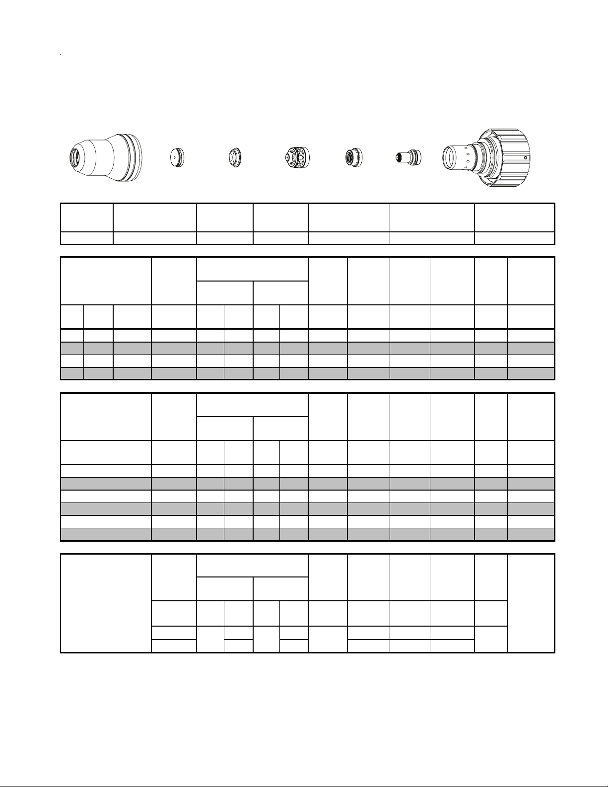
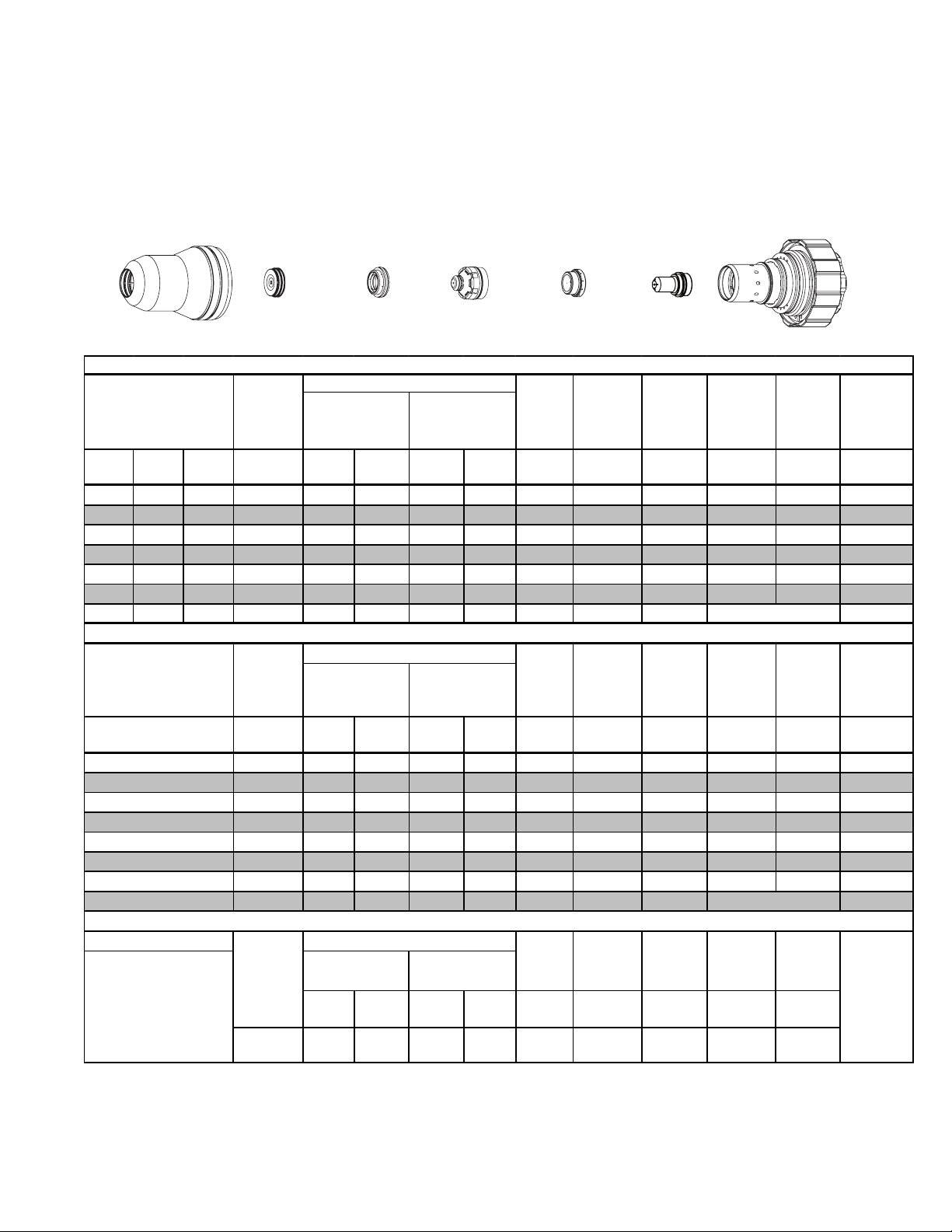
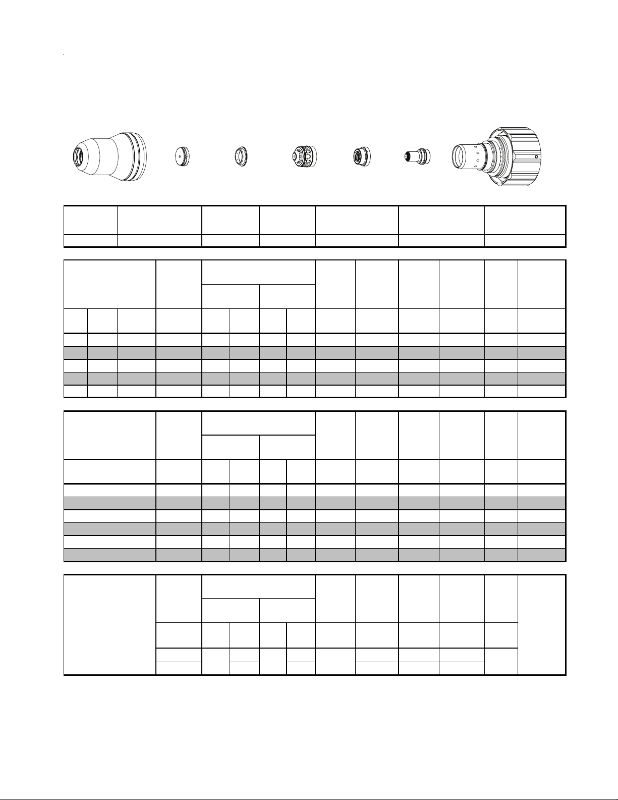
Aluminium
30A
Air Plasma / Air Shield
Shield Cup
Shield Cap
Shield Gas
Distributor
Tip
This Art Is For Reference ONLY
)
2
Shield Gas
Distributor
Cut Flow Rate s /
Pressures
Cut Flow Rate s /
Pressures Arc
Plas m a (O
Plas m a (N
(Ball)
20 70 93 0
2
Cut Flow Rate s /
Pressures Arc
2
(PSI) /
(Bar)
Tip
) Shield (Air)
Marking
) Shield (N2)
(PSI) /
(Ball)
(Bar)
BOLD ITALIC
Shield Cup Shield Cap
Mate ri al
Thickn es s
(ga) (in) inch (PSI) (Ball) (PSI) (Ball) (PSI) Volts
25 0.025 60 60 120 15 120 86 0.020 500 0.040 0.0 0.029
21 0.037 60 60 120 15 120 86 0.020 240 0.060 0.1 0.046
18 0.052 60 60 120 15 120 84 0.020 230 0.100 0.2 0.034
16 0.064 60 60 120 15 120 80 0.020 220 0.100 0.2 0.036
Mate ri al
Thickn es s
(mm)
1
2
16A Arc Cur r e nt
Burn-through
may occur
for th ickn es s es
< 1/16" (0.063") / 1.6
mm.
BOLD TYPE
indicates maximum piercing parameters.
Pre Flow
Pressure
(Air)
Pre Flow
Pressure
(Air)
(Bar) (Ball) (Bar) (Ball) (Bar) Volts
4.1 60 8.3 15 8.3 86 0.5 6060 1.7 0.1 0.9
4.1 60 8.3 15 8.3 75 0.5 5280 2.5 0.2 0.9
Pre Flow
Pressure
(N
(PSI) /
(Bar)
20 40 80 0.100 300 0.100
1.4 2.8 5.5 2.5 7600 2.5
Plasma Gas
Distributor
Plasma Gas
Distributor
22-1045 22-1077 22-102022-1016 22-1033 22-1274 22-1059
Arc
Vol tag e
Vol tag e
Vol tag e
Vol ts
Torch
Working
Height
(in)
±0.005
Torch
Working
Height
(mm)
±0.1
Torch
Working
Height
in ±0.005 /
mm ±0. 1
indicates edge starts only.
Electrode
Cartridge
Art # A-07958_AB
Electrode Cartridge
(sec)
Kerf Width
@ Rec.
SpeedPlas m a (Air) Shield (Air)
Kerf Width
@ Rec.
Speed
Mar ki ng
quality
degrades
thi ckn es s
decreases
Travel
Speed
(ipm ) (in) (s ec) (in)
Travel
Speed
( mm/mi n)
Travel
Speed
ipm /
mm/min
Initial
Piercing
Height
Initial
Piercing
Height
(mm) (sec) (mm)
Initial
Tran s fer
Height
in ±0.005 /
mm ±0.1
Pierce
Delay
Pierce
Delay
Pierce
Delay
as
TORCH DATA for Ultra-Cut 8-12 Manual 0-4829 Rev AN
Page 11
Aluminium
30A
N
Plasma / H2O Shield
2
Shield Cup
Shield Cap
Shield Gas
Distributor
Tip
This Art Is For Reference ONLY
Shield Cup Shield Cap
Mate ri al
Thickn es s
(ga) (in) inch (PSI) (Ball) (PSI) (Ball) (PSI) Volts
25 0.025 96 55 120 4 55 103 0.03 230 0.08 0 0.034
21 0.037 96 55 120 4 55 103 0.03 220 0.08 0.1 0.045
18 0.052 96 55 120 4 55 103 0.03 150 0.08 0.2 0.031
16 0.064 96 55 120 4 55 103 0.03 110 0.08 0.2 0.036
Mate ri al
Thickn es s
(mm)
1
2
16A Arc Cur r e nt
Burn-through
may occur
for thickn es s es
< 1/16" (0.063") / 1.6
mm.
BOLD TYPE
indicates maximum piercing parameters.
Pre Flow
Pressure
(N
Pre Flow
Pressure
(N
(Bar) (Ball) (Bar) (Ball) (Bar) Volts
6.6 55 8.3 4 3.8 103 0.8 5310 2.0 0.1 1.1
6.6 55 8.3 4 3.8 103 0.8 1550 2.0 0.2 1.0
Pre Flow
Pressure
(N
(PSI) /
(Bar)
20 40 80 0.100 300 0.100
1.4 2.8 5.5 2.5 7600 2.5
Shield Gas
Distributor
Cut Flo w Rates /
Pressures
)
2
Plas m a (N
)
2
Plas m a (N
)
2
(Ball)
20 70 93
) Shield (H2O)
2
Cut Flo w Rates /
Pressures Arc
) Shield (H2O)
2
Cut Flo w Rates /
Pressures Arc
) Shield (N2)
2
(PSI) /
(Ball)
(Bar)
Tip
Marking
(PSI) /
(Bar)
BOLD ITALIC
Plasma Gas
Distributor
Plasma Gas
Distributor
22-1045 22-1077 22-102022-1016 22-1033 22-1274 22-1059
Arc
Vol tag e
Vol tag e
Vol tag e
Vo lt s
Torch
Working
Height
(in)
±0.005
Torch
Working
Height
(mm )
±0.1
Torch
Working
Height
in ±0.005 /
mm ±0. 1
indicates edge starts only.
Electrode
Cartridge
Art # A-07958_AB
Electrode Cartridge
(sec)
0
Kerf Width
@ Rec.
SpeedPlas m a (N
Kerf Width
@ Rec.
Speed
Mar ki ng
quality
degrades
thi ckn es s
decreases
Travel
Speed
(ipm ) (in) (sec) (in)
Travel
Speed
( mm/mi n)
Travel
Speed
ipm /
mm/ min
Initial
Piercing
Height
Initial
Piercing
Height
(mm ) (sec) (m m )
Initial
Transfer
Height
in ±0.005 /
mm ±0. 1
Pierce
Delay
Pierce
Delay
Pierce
Delay
as
Manual 0-4829 Rev AN 8-13 TORCH DATA for Ultra-Cut
Page 12
Mild Steel
50A
Plasma / Air Shield
O
2
Shield Cup
Shield Cap
Shield Gas
Distributor
Tip
This Art Is For Reference ONLY
Shield Cup Shield Cap
Mate ri al
Thickn es s
(ga) (in) inch (PSI) (Ball) (PSI) (Ball) (PSI) Volts
14 0.075 70 28 120 20 120 130 0.060 280 0.100 0.0 0.040
12 0.105 70 28 120 20 120 130 0.060 270 0.100 0.0 0.052
10 0.135 70 28 120 20 120 126 0.040 160 0.100 0.4 0.044
3/16 0.188 70 28 120 40 120 130 0.060 100 0.110 0.4 0.054
1/4 0.250 70 28 120 40 120 132 0.060 90 0.110 0.4 0.062
Mate ri al
Thickn es s
(mm)
2
3
4
5
6
18A Arc Cur r e nt
Burn-through
may occur
for th ickn es s es
< 1/16" (0.063") / 1.6
mm.
BOLD TYPE
indicates maximum piercing parameters.
Pre Flow
Pressure
(Air)
Pre Flow
Pressure
(Air)
(Bar) (Ball) (Bar) (Ball) (Bar) Volts
4.8 28 8.3 20 8.3 130 1.5 7110 2.5 0.0 1.1
4.8 28 8.3 20 8.3 128 1.3 5640 2.5 0.2 1.2
4.8 28 8.3 20 8.3 128 1.2 3420 2.7 0.4 1.2
4.8 28 8.3 40 8.3 130 1.5 2500 2.8 0.4 1.4
4.8 28 8.3 40 8.3 132 1.5 2340 2.8 0.4 1.5
Pre Flow
Pressure
(N
(PSI) /
(Bar)
20 40 80 0.120 300 0.120
1.4 2.8 5.5 7600 7600 3.0
Shield Gas
Distributor
Cut Flow Rate s /
Pressures
) Shield (Air)
2
Cut Flow Rate s /
Pressures Arc
Plas m a (O
Plas m a (N
)
2
(Ball)
40 75 143
) Shield (Air)
2
Cut Flow Rate s /
Pressures Arc
) Shield (N2)
2
(PSI) /
(Ball)
(Bar)
Tip
Marking
(PSI) /
(Bar)
BOLD ITALIC
Plasma Gas
Distributor
Plasma Gas
Distributor
22-1041 22-1069 22-102022-1016 22-1025 22-1272 22-1051
Arc
Vol tag e
Vol tag e
Vol tag e
Vol ts
Torch
Working
Height
(in)
±0.005
Torch
Working
Height
(mm)
±0.1
Torch
Working
Height
in ±0.005 /
mm ±0. 1
indicates edge starts only.
Electrode
Cartridge
Art # A-07958_AB
Electrode Cartridge
Travel
Speed
(ipm ) (in) (s ec) (in)
Travel
Speed
( mm/mi n)
Travel
Speed
ipm /
mm/min
Initial
Piercing
Height
Initial
Piercing
Height
(mm ) (sec) (m m )
Initial
Tran s fer
Height
in ±0.005 /
mm ±0.1
Pierce
Delay
Pierce
Delay
Pierce
Delay
(sec)
0
Kerf Width
@ Rec.
Kerf Width
@ Rec.
Mar ki ng
degrades
thi ckn es s
decreases
SpeedPlas m a (O
Speed
quality
as
TORCH DATA for Ultra-Cut 8-14 Manual 0-4829 Rev AN
Page 13
Stainless Steel
50A
Air Plasma / Air Shield
Shield Cup
Shield Cap
Shield Gas
Distributor
Tip
This Art Is For Reference ONLY
Shield Cup Shield Cap
Mate ri al
Thickn es s
(ga) (in) inch (PSI) (Ball) (PSI) (Ball) (PSI) Volts
14 0.078 100 62 120 75 120 109 0.060 180 0.120 0.0 0.044
12 0.109 100 62 120 75 120 114 0.060 130 0.150 0.0 0.049
10 0.141 100 62 120 75 120 118 0.060 120 0.180 0.1 0.050
3/16
Mate ri al
Thickn es s
0.188 100 62 120 75 120 124 0.080 70 0.200 0.3 0.059
Pre Flow
Pressure
(Air)
Pre Flow
Pressure
(Air)
Shield Gas
Distributor
Cut Flow Rate s /
Pressures
Cut Flow Rate s /
Pressures Arc
Plas m a (Air) Shield (Air)
Tip
Plasma Gas
Distributor
Plasma Gas
Distributor
22-1041 22-1078 22-102022-1016 22-1034 22-1274 22-1060
Arc
Vol tag e
Vol tag e
Torch
Working
Height
(in)
±0.005
Torch
Working
Height
Electrode
Cartridge
Art # A-07958_AB
Electrode Cartridge
Travel
Speed
(ipm ) (in) (s ec) (in)
Travel
Speed
Initial
Piercing
Height
Initial
Piercing
Height
Pierce
Delay
Pierce
Delay
Kerf Width
@ Rec.
SpeedPlas m a (Air) Shield (Air)
Kerf Width
@ Rec.
Speed
(mm)
1.5
2.0
3.0
4
5
16A Arc Cur r e nt
Burn-through
may occur
for th ickn es s es
< 1/16" (0.063") / 1.6
mm.
BOLD TYPE
indicates maximum piercing parameters.
(Bar) (Ball) (Bar) (Ball) (Bar) Volts
6.9 62.0 8.3 75.0 8.3 106.0 1.5 5350.0 2.6 0.0 1.0
6.9 62.0 8.3 75.0 8.3 109.0 1.5 4540.0 3.1 0.0 1.1
6.9 62.0 8.3 75.0 8.3 115.0 1.5 3229.7 4.0 0.0 1.3
6.9 62.0 8.3 75.0 8.3 120.0 1.7 2600.0 4.8 0.2 1.4
6.9 62.0 8.3 75.0 8.3 125.0 2.1 1520.0 5.2 0.3 1.5
Marking
Pre Flow
Pressure
)
(N
2
(PSI) /
(Bar)
20 40 80 0.120 300 0.120
1.4 2.8 5.5 3.0 7600 3.0
Cut Flow Rate s /
Pressures Arc
(Bar)
Vol tag e
Vol ts
Plas m a (N
(Ball)
40 75 120 0
) Shield (N2)
2
(PSI) /
(Bar)
(Ball)
(PSI) /
BOLD ITALIC
(mm)
±0.1
Torch
Working
Height
in ±0.005 /
mm ±0. 1
indicates edge starts only.
( mm/mi n)
Travel
Speed
ipm /
mm/min
(mm ) (sec) (m m )
Initial
Tran s fer
Height
in ±0.005 /
mm ±0.1
Pierce
Delay
(sec)
Mar ki ng
quality
degrades
as
thi ckn es s
decreases
Manual 0-4829 Rev AN 8-15 TORCH DATA for Ultra-Cut
Page 14
C
g
Stainless Steel
50A
Plasma / H2O Shield
N
2
Shield Cup
Shield Cap
Shield Gas
Distributor
Tip
This Art Is For Reference ONLY
Shield Cup Shield Cap Shield Gas
Distributor
22-1016 22-1034 22-1274 22-1060
Mate ri al
Thickness
Pre Flow
Pressure
(N
)
2
(ga) (in) inch (PSI) Ball (PSI) Ball (PSI) Volts
ut Flow Rates /
Pressures
Plas m a (N
Tip Plasma Gas
Shield
)
2
(H
O)*
2
Plasma Gas
Distributor
Electrode
Cartridge
Art # A-07958_AB
Elec trode
Distributor
22-1041 22-1078 22-1020
Arc
Voltage
Torch
Working
Height
(in)
±0.005
Travel
Speed
(ipm ) (in) (s ec) (in)
Initial
Piercing
Height
Pierce
Delay
Cartridge
Kerf Width
@ Rec.
Speed
14 0.078 60 62 120 4 55 117 0.110 170 0.200 0.2 0.043
12 0.109 60 62 120 4 55 119 0.110 150 0.200 0.2 0.047
Cut Flow Ra tes /
Pressures
Plas m a (N
Arc
Shield
)
2
(H
2
Voltage
O)*
Torch
Working
Height
(mm )
±0.1
Travel
Speed
( mm/mi n)
Initial
Piercing
Height
Pierce
Delay
(mm ) (s ec) (mm )
Kerf Width
@ Rec.
Speed
Mate ri al
Thickness
(mm)
2
3
Pre Flow
Pressure
(N
)
2
(Bar) Ball (Bar) Ball (Bar) Volts
4.1 62 8.3 4 3.8 117 2.8 4310 5.1 0.2 1.1
4.1 62 8.3 4 3.8 120 2.8 3660 5.1 0.2 1.2
Marking
16A Arc Cur r e nt
Burn-through
may occur
for thicknes s es
< 1/16" (0.063") / 1.6
mm.
BOLD TYPE
indicates maximum piercing parameters.
Pre Flow
Pressure
)
(N
2
(PSI) /
(Bar)
20 40 80 0.120 300 0.120
1.4 2.8 5.5 3.0 7600 3.0
Cut Flow Ra tes /
Pressures Arc
Plas m a (N
(PSI) /
(Ball)
(Bar)
) Shield (N2)
2
(PSI) /
(Ball)
(Bar)
Voltage
Vol ts
Torch
Working
Height
in ±0.005 /
mm ±0. 1
Travel
Speed
ipm /
mm/ mi n
Initial
Transfer
Height
in ±0.005 /
mm ±0. 1
40 75 120 0
Pierce
Delay
(sec)
Mar ki ng
quality
degrades
thi ckn es s
decreases
Requires CCM version 3.4 or later. Requires GCM version 3.2 or later
* Pressure of the water supply line should be regulated by customer pressure regulator.
Ohmic height sensing is not recommended with water shield. Water on the plate interferes electrically with the
Note1:
ohmic sensin
Water source used for shield must be demineralized.
Note2:
circuit.
as
TORCH DATA for Ultra-Cut 8-16 Manual 0-4829 Rev AN
Page 15
Aluminium
50A
Air Plasma / Air Shield
Shield Cup
Shield Cap
Shield Gas
Distributor
Tip
This Art Is For Reference ONLY
Shield Cup Shield Cap
Mate ri al
Thickn es s
(ga) (in) inch (PSI) (Ball) (PSI) (Ball) (PSI) Volts
16 0.064 100 60 120 75 120 124 0.100 140 0.200 0.0 0.060
12 0.097 100 60 120 75 120 125 0.105 90 0.200 0.0 0.067
11 0.120 100 60 120 75 120 129 0.110 60 0.200 0.0 0.068
3/16 0.188 100 60 120 75 120 133 0.120 40 0.200 0.2 0.074
Mate ri al
Thickn es s
Pre Flow
Pressure
(Air)
Pre Flow
Pressure
(Air)
Shield Gas
Distributor
Cut Flo w Rates /
Pressures
Cut Flo w Rates /
Pressures Arc
Plas m a (Air) Shield (Air)
Tip
Plasma Gas
Distributor
Plasma Gas
Distributor
22-1041 22-1078 22-102022-1016 22-1034 22-1274 22-1060
Arc
Vol tag e
Vol tag e
Torch
Working
Height
(in)
±0.005
Torch
Working
Height
Electrode
Cartridge
Art # A-07958_AB
Electrode Cartridge
Travel
Speed
(ipm ) (in) (sec) (in)
Travel
Speed
Initial
Piercing
Height
Initial
Piercing
Height
Pierce
Delay
Pierce
Delay
Kerf Width
@ Rec.
SpeedPlas m a (Air) Shield (Air)
Kerf Width
@ Rec.
Speed
(mm)
2
3
4
5
16A Arc Cur r e nt
Burn-through
may occur
for thickn es s es
< 1/16" (0.063") / 1.6
mm.
BOLD TYPE
indicates maximum piercing parameters.
(Bar) (Ball) (Bar) (Ball) (Bar) Volts
6.9 60 8.3 75 8.3 124 2.6 2990 5.1 0.0 1.6
6.9 60 8.3 75 8.3 129 2.8 1520 5.1 0.0 1.7
6.9 60 8.3 75 8.3 131 2.9 1240 5.1 0.1 1.8
6.9 60 8.3 75 8.3 134 3.1 950 5.1 0.2 1.9
Marking
Pre Flow
Pressure
)
(N
2
(PSI) /
(Bar)
20 40 80 0.120 300 0.120
1.4 2.8 5.5 3.0 7600 3.0
Cut Flo w Rates /
Pressures Arc
(Bar)
Vol tag e
Vo lt s
Plas m a (N
(Ball)
40 75 120 0
) Shield (N2)
2
(PSI) /
(Ball)
(Bar)
(PSI) /
BOLD ITALIC
(mm )
±0.1
Torch
Working
Height
in ±0.005 /
mm ±0. 1
indicates edge starts only.
( mm/mi n)
Travel
Speed
ipm /
mm/ min
(mm ) (sec) (m m )
Initial
Transfer
Height
in ±0.005 /
mm ±0. 1
Pierce
Delay
(sec)
Mar ki ng
quality
degrades
as
thi ckn es s
decreases
Manual 0-4829 Rev AN 8-17 TORCH DATA for Ultra-Cut
Page 16

g
Aluminum
50A
N
Plasma / H2O Shield
2
Shield Cup
Shield Cap
Shield Gas
Distributor
This Art Is For Reference ONLY
Shield Cup Shield Cap Shield Gas
Distributor
Tip
Tip Plas m a Gas
Plasma Gas
Distributor
Distributor
Electrode
Cartridge
Art # A-07958_AB
Electrode Cartridge
22-1041 22-1078 22-102022-1016 22-1034 22-1274 22-1060
Mate ri al
Thickn es s
Pre Flow
Pres sure
)
(N
2
(ga) (in) inch (PSI) Ball (PSI) Ball (PSI) Volts
Cut Flo w Rates /
Pressures
Plas m a (N
Arc
Shield
)
2
(H
2
Vol tag e
O)*
Torch
Working
Height
(in)
±0.005
Travel
Speed
(ipm ) (in) (s ec) (in)
Initial
Piercing
Height
Pierce
Delay
Kerf Width
@ Rec.
Speed
16 0.064 100 60 120 4 55 120 0.11 140 0.200 0.2 0.045
12 0.097 100 60 120 4 55 120 0.11 90 0.200 0.2 0.046
11 0.120 100 60 120 4 55 123 0.11 60 0.200 0.2 0.050
3/16 0.188 100 60 120 4 55 125 0.12 40 0.200 0.2 0.051
Cut Flo w Rates /
Pressures
Plas m a (N
Arc
Shield
)
2
(H
2
Vol tag e
O)*
Torch
Working
Height
(mm)
±0.1
Travel
Speed
( mm/mi n)
Initial
Piercing
Height
Pierce
Delay
Kerf Width
@ Rec.
Speed
(mm) (sec) (mm)
Mate ri al
Thickn es s
(mm)
2
3
4
5
Pre Flow
Pres sure
)
(N
2
(Bar) Ball (Bar) Ball (Bar) Volts
6.9 60 8.3 4 3.8 120 2.8 2990 5.1 0.2 1.2
6.9 60 8.3 4 3.8 123 2.8 1520 5.1 0.2 1.3
6.9 60 8.3 4 3.8 124 2.9 1240 5.1 0.2 1.3
6.9 60 8.3 4 3.8 125 3.1 950 5.1 0.2 1.3
Marking
16 A Arc Curre nt
Burn-through
may occur
for thickn es s es
< 1/16" (0.063") / 1.6
mm.
BOLD TYPE
indicates maximum piercing parameters.
Pre Flow
Pres sure
)
(N
2
(PSI) /
(Bar)
20 40 80 0.120 300 0.120
1.4 2.8 5.5 3.0 7600 3.0
Cut Flo w Rates /
Pressures Arc
Plas m a (N
(Ball)
) Shield (N2)
2
(PSI) /
(Bar)
(Ball)
(PSI) /
(Bar)
Vol tag e
Vol ts
Torch
Working
Height
in ±0.005 /
mm ±0. 1
Travel
Speed
ipm /
mm/min
Initial
Transfer
Height
in ±0.005 /
mm ±0. 1
40 75 120 0
Pierce
Delay
(sec)
Mark in g
quality
degrades
thickness
decreases
Requires CCM version 3.4 or later. Requires GCM version 3.2 or later
* Pressure of the water supply line should be regulated by customer pressure regulator.
Ohmic height sensing is not recomm ended with water shield. Water on the plate interferes electrically with the
Note1:
ohmic sensin
Water source used for shield mus t be demineralized.
Note2:
circuit.
as
TORCH DATA for Ultra-Cut 8-18 Manual 0-4829 Rev AN
Page 17
Mild Steel
70A
O
Plasma / Air Shield
2
Shield Cup
22-1016
Shield Cap
22-1026
Shield
Gas Distributor
22-1272
Tip
22-1152
Plasma
Gas Distributor
22-1041
Cartridge
22-1020Electrode
22-1170
Art # A-07663
70A Mild Steel XTL (O2/Air)
Mate ri al
Thickn es s
(ga) (in) inch (PSI) Ball (PSI) Ball (PSI) Volts
Pre Flow
Pressure
(Air)
Cut Flow Rate s / Pres s ures
Plas m a (O2) 5Shield (Air)
Arc
Vol tag e
Torch
Workin g
Height
(in)
±0.005
Travel
Speed
(ipm ) (in) (sec) (in)
Initial
Piercing
Height
Pierce
Delay
Kerf
Width
@ Rec.
Speed
16 0.060 46 35 120 41 120 138 0.070 300 0.100 0.1 0.073
14 0.075 46 35 120 41 120 138 0.070 300 0.100 0.1 0.072
12 0.105 46 55 120 60 120 142 0.080 270 0.120 0.2 0.078
10 0.135 46 55 120 60 120 142 0.080 180 0.150 0.2 0.071
3/16 0.188 46 55 120 60 120 148 0.100 130 0.200 0.4 0.077
1/4 0.250 46 55 120 60 120 148 0.100 100 0.200 0.5 0.083
Mate ri al
Thickn es s
(mm)
1.5
2
3
4
6
16A Arc Current
Burn-through
may occur
on thickness es
< 1/16" (0.063") /
1.6 mm.
Pre Flow
Pressure
(Air)
(Bar) Ball (Bar) Ball (Bar) Volts
Cut Flow Rate s / Pres s ures
Plas m a (O2)
Shield (Air)
Arc
Vol tag e
Torch
Workin g
Height
(mm)
±0.1
Travel
Speed
(mm/min) (mm) (sec) (mm)
Initial
Piercing
Height
Pierce
Delay
3.2 35 8.3 41 8.3 138 1.8 7620 2.5 0.1 1.9
3.2 35 8.3 41 8.3 138 1.8 7530 2.6 0.1 1.9
3.2 55 8.3 60 8.3 142 2.0 5860 3.4 0.2 1.9
3.2 55 8.3 60 8.3 145 2.3 4030 4.4 0.3 1.9
3.2 55 8.3 60 8.3 148 2.5 3190 5.1 0.4 2.0
3.2 55 8.3 60 8.3 148 2.5 2710 5.1 0.5
Marking (with 70A Mild Steel Parts)
Pre Flow
Pr e s s u r e
(
)
N
2
20 psi
1.4 bar
Cut Flow Rate s / Pres s ures
)
Pressure (
Shield
Plasma
Pressure (
N
2
Ball Press Ball Press
50
40 psi
2.8 bar
80
80 psi
5.5 bar
Arc
Vol tag e
)
N
2
Vol ts
155
Tor ch
Working
Height
in ±0.005 /
mm ±0.1
0.12
3
Travel
Speed
ipm /
mm/min
300
7600
Initial
Piercing
Height
in ±0.0 05 /
mm ±0.1
0.12
3
Pierce
Delay
sec
0
Kerf
Width
@ Rec.
Speed
2.1
Marking
quality
degrades
as
thic knes s
decreas es.
Manual 0-4829 Rev AN 8-19 TORCH DATA for Ultra-Cut
Page 18

Stainless Steel
70A
Air Plasma / Air Shield
Shield Cup
Shield Cap
Shield Gas
Distributor
Tip
This Art Is For Reference ONLY
Shield Cup Shield Cap
22-1016
Mate ri al
Thickn es s
(ga) (in) inch (PSI) (Ball) (PSI) (Ball) (PSI) Volts
10 0.141 84 41 120 94 120 138 0.080 120 0.140 0.3 0.075
3/16 0.188 84 41 120 87 120 144 0.080 100 0.140 0.4 0.082
1/4 0.250 84 41 120 72 120 148 0.130 55 0.180 0.5 0.085
3/8 0.375 84 41 120 72 120 152 0.140 40 0.200 0.6 0.083
1/2 0.500 84 53 120 60 120 160 0.140 25 0.280 0.8 0.080
Mate ri al
Thickn es s
22-1035 22-1274 22-1061 22-1041 22-1079 22-1020
Pre Flow
Pressure
(Air)
Pre Flow
Pressure
(Air)
Shield Gas
Distributor
Cut Flow Rate s /
Pressures
Cut Flow Rate s /
Pressures Arc
Plas m a (Air) Shield (Air)
Tip
Plasma Gas
Distributor
Plasma Gas
Distributor
Arc
Vol tag e
Vol tag e
Torch
Working
HeightPlas m a (Air) Shield (Air)
(in)
±0.005
Torch
Working
Height
Electrode
Cartridge
Art # A-07958_AB
Electrode Cartridge
Travel
Speed
(ipm ) (in) (s ec) (in)
Travel
Speed
Initial
Piercing
Height
Initial
Piercing
Height
Pierce
Delay
Pierce
Delay
Kerf Width
Kerf Width
@ Rec.
Speed
@ Rec.
Speed
(mm)
3
4
5
6
8
10
12
16A Arc Cur r e nt
Burn-through
may occur
for th ickn es s es
< 1/16" (0.063") / 1.6
mm.
BOLD TYPE
indicates maximum piercing parameters.
(Bar) (Ball) (Bar) (Ball) (Bar) Volts
5.8 41 8.3 94 8.3 135 2.0 3300 3.6 0.3 1.8
5.8 41 8.3 94 8.3 140 2.0 2870 3.6 0.3 2.0
5.8 41 8.3 87 8.3 145 2.2 2380 3.7 0.4 2.1
5.8 41 8.3 72 8.3 148 2.3 1440 4.5 0.5 2.1
5.8 41 8.3 72 8.3 150 2.4 1200 4.8 0.6 2.1
5.8 41 8.3 72 8.3 153 3.6 960 5.4 0.6 2.1
5.8 53 8.3 60 8.3 158 3.6 720 6.7 0.8 2.1
Marking
Pre Flow
Pressure
(N
)
2
(PSI) /
(Bar)
20 40 80 0.120 300 0.120
1.4 2.8 5.5 3.0 7600 3.0
Cut Flow Rate s /
Pressures Arc
Plas m a (N
(Ball)
50 75
) Shield (N2)
2
(PSI) /
(Bar)
(Ball)
(PSI) /
(Bar)
Vol tag e
Vol ts
135 0
(mm)
±0.1
Torch
Working
Height
in ±0.005 /
mm ±0. 1
( mm/mi n)
Travel
Speed
ipm /
mm/min
(mm ) (sec) (m m )
Initial
Tran s fer
Height
in ±0.005 /
mm ±0.1
Pierce
Delay
(sec)
Mar ki ng
quality
degrades
as
thi ckn es s
decreases
TORCH DATA for Ultra-Cut 8-20 Manual 0-4829 Rev AN
Page 19
2
Stainless Steel
70A
Plasma / H2O Shield
N
2
Shield Cup
Shield Cap
Shield Gas
Distributor
Tip
This Art Is For Reference ONLY
)
2
Shield Gas
Distributor
Plas m a (N
Plas m a (N
(Ball)
Tip
Cut Flo w Rates /
Pressures
Shield
)
2
(H
2
Cut Flo w Rates /
Pressures Arc
Shield
)
2
(H
Cut Flo w Rates /
Pressures Arc
) Shield (N2)
2
(PSI) /
50 75
(Bar)
(Ball)
O)*
O)*
Marking
(PSI) /
(Bar)
Shield Cup Shield Cap
22-1016 22-1084 22-1020
Mate ri al
Thickn es s
(ga) (in) inch (PSI) (Ball) (PSI) (Ball) (PSI) Volts
10 0.141 45 55 90 5 55 146 0.100 120 0.250 0.3 0.075
3/16 0.188 45 55 90 5 55 150 0.100 90 0.250 0.4 0.086
1/4 0.250 45 55 90 5 55 159 0.150 50 0.250 0.5 0.095
3/8 0.375 45 55 90 5 55 168 0.150 35 0.250 0.7 0.103
Mate ri al
Thickn es s
(mm)
3
4
5
6
8
10
18A Arc Cur r e nt
Burn-through
may occur
for thickn es s es
< 1/16" (0.063") / 1.6
mm.
BOLD TYPE
22-1047 22-1274 22-1064
Pre Flow
Pressure
(Air)
Pre Flow
Pressure
(Air)
(Bar) (Ball) (Bar) (Ball) (Bar) Volts
3.1 55 6.2 5 3.8 142 2.5 3040 6.3 0.3 1.8
3.1 55 6.2 5 3.8 143 2.5 2780 6.3 0.3 2.0
3.1 55 6.2 5 3.8 151 2.5 2140 6.3 0.4 2.2
3.1 55 6.2 5 3.8 157 3.8 1495 6.3 0.5 2.3
3.1 55 6.2 5 3.8 164 3.8 1070 6.3 0.6 2.5
3.1 55 6.2 5 3.8 170 3.8 980 6.3 0.7 2.6
Pre Flow
Pressure
(N
(PSI) /
(Bar)
20 40 80 0.120 300 0.120
1.4 2.8 5.5 3.0 7600 3.0
indicates maximum piercing parameters.
Plasma Gas
Distributor
Plasma Gas
Distributor
22-1041
Arc
Vol tag e
Vol tag e
Vol tag e
Vo lt s
150 0
Torch
Working
HeightPlasma (N
±0.005
Torch
Working
Height
(mm )
±0.1
Torch
Working
Height
in ±0.005 /
mm ±0. 1
(in)
Electrode
Electrode Cartridge
Travel
Speed
(ipm ) (in) (sec) (in)
Travel
Speed
( mm/mi n)
Travel
Speed
ipm /
mm/ min
Cartridge
Art # A-07958_AB
Initial
Piercing
Height
Initial
Piercing
Height
(mm ) (sec) (m m )
Initial
Transfer
Height
in ±0.005 /
mm ±0. 1
Pierce
Delay
Pierce
Delay
Pierce
Delay
(sec)
Kerf Width
@ Rec.
Speed
Kerf Width
@ Rec.
Speed
Mar ki ng
quality
degrades
thi ckn es s
decreases
as
Manual 0-4829 Rev AN 8-21 TORCH DATA for Ultra-Cut
Page 20
Aluminium
70A
Air Plasma / Air Shield
Shield Cup
Shield Cap
Shield Gas
Distributor
Tip
This Art Is For Reference ONLY
Shield Cup Shield Cap
Mate ri al
Thickn es s
(ga) (in) inch (PSI) (Ball) (PSI) (Ball) (PSI) Volts
14 0.079 84 42 120 70 120 153 0.060 300 0.140 0.0 0.058
12 0.097 84 42 120 70 120 160 0.080 200 0.140 0.1 0.062
3/16 0.188 84 42 120 70 120 162 0.120 100 0.140 0.1 0.072
1/4 0.250 84 42 120 70 120 166 0.140 70 0.180 0.2 0.073
3/8 0.375 84 42 120 70 120 168 0.140 60 0.180 0.3 0.078
Mate ri al
Thickn es s
Pre Flow
Pressure
(Air)
Pre Flow
Pressure
(Air)
Shield Gas
Distributor
Cut Flow Rate s /
Pressures
Cut Flow Rate s /
Pressures Arc
Plas m a (Air) Shield (Air)
Tip
Plasma Gas
Distributor
Plasma Gas
Distributor
22-1041 22-1079 22-102022-1016 22-1035 22-1274 22-1061
Arc
Vol tag e
Vol tag e
Torch
Working
Height
(in)
±0.005
Torch
Working
Height
Electrode
Cartridge
Art # A-07958_AB
Electrode Cartridge
Travel
Speed
(ipm ) (in) (s ec) (in)
Travel
Speed
Initial
Piercing
Height
Initial
Piercing
Height
Pierce
Delay
Pierce
Delay
Kerf Width
@ Rec.
SpeedPlas m a (Air) Shield (Air)
Kerf Width
@ Rec.
Speed
(mm)
2
3
4
5
6
8
10
16A Arc Cur r e nt
Burn-through
may occur
for th ickn es s es
< 1/16" (0.063") / 1.6
mm.
BOLD TYPE
indicates maximum piercing parameters.
(Bar) (Ball) (Bar) (Ball) (Bar) Volts
5.8 42 8.3 70 8.3 153 1.5 7620 3.6 0.0 1.5
5.8 42 8.3 70 8.3 160 2.3 4490 3.6 0.1 1.6
5.8 42 8.3 70 8.3 161 2.7 3390 3.6 0.1 1.7
5.8 42 8.3 70 8.3 163 3.1 2430 3.7 0.1 1.8
5.8 42 8.3 70 8.3 165 3.4 1950 4.4 0.2 1.9
5.8 42 8.3 70 8.3 167 3.6 1650 4.6 0.3 2.0
5.8 42 8.3 70 8.3 168 3.6 1490 4.6 0.3 2.0
Marking
Pre Flow
Pressure
)
(N
2
(PSI) /
(Bar)
20 40 80 0.120 300 0.120
1.4 2.8 5.5 3.0 7600 3.0
Cut Flow Rate s /
Pressures Arc
Plas m a (N
(Ball)
50 75
) Shield (N2)
2
(PSI) /
(Bar)
(Ball)
Vol tag e
(PSI) /
(Bar)
BOLD ITALIC
Vol ts
135 0
(mm)
±0.1
Torch
Working
Height
in ±0.005 /
mm ±0. 1
indicates edge starts only.
( mm/mi n)
Travel
Speed
ipm /
mm/min
Tran s fer
Height
in ±0.005 /
mm ±0.1
(mm ) (sec) (m m )
Initial
Pierce
Delay
(sec)
Mar ki ng
quality
degrades
as
thi ckn es s
decreases
TORCH DATA for Ultra-Cut 8-22 Manual 0-4829 Rev AN
Page 21
Aluminum
g
70A
N
Plasma / H2O Shield
2
Shield Cup
Shield Cap
Shield Gas
Distributor
Tip
Plasma Gas
Distributor
Electrode
Cartridge
This Art Is For Reference ONLY
Shield Cup Shield Cap Shield Gas
Distribut or
Tip P l as m a Gas
Distributor
Electrode Cartridge
Art # A-07958_AB
22-1041 22-1084 22-102022-1016 22-1047 22-1274 22-1064
Mate ri al
Thicknes s
Pre Flow
Pressure
)
(N
2
(ga) (in) inch (PSI) Ball (PSI) Ball (PSI) Volts
Cut Flow Rates /
Pressures
Plasma (N
Arc
Shield
)
2
(H
2
Voltage
O)*
Torch
Working
Height
(in)
±0.005
Travel
Speed
(ipm ) (in) (s ec) (in)
Initial
Piercing
Height
Pierce
Delay
Kerf Width
@ Rec.
Speed
16 0.064 45 55 90 5 55 155 0.100 300 0.250 0 0.057
14 0.079 45 55 90 5 55 148 0.100 240 0.250 0 0.068
12 0.097 45 55 90 5 55 150 0.150 200 0.250 0.1 0.095
3/16 0.188 45 55 90 5 55 150 0.150 120 0.250 0.3 0.095
1/4 0.250 45 55 90 5 55 158 0.150 70 0.250 0.3 0.097
3/8 0.375 45 55 90 5 55 162 0.150 35 0.250 0.5 0.100
Cut Flow Rates /
Pressures
Plasma (N
Arc
Shield
)
2
(H
2
Voltage
O)*
Torch
Working
Height
(mm)
±0.1
Travel
Speed
( mm/mi n)
Initial
Piercing
Height
Pierce
Delay
Kerf Width
@ Rec.
Speed
(mm) (s ec) (mm )
Mate ri al
Thicknes s
(mm)
2
3
4
5
6
7
8
Pre Flow
Pressure
)
(N
2
(Bar) Ball (Bar) Ball (Bar) Volts
3.1 55 6.2 5 3.8 148 2.5 6100 6.3 0 1.7
3.1 55 6.2 5 3.8 150 3.8 4610 6.3 0.2 2.4
3.1 55 6.2 5 3.8 150 3.8 3730 6.3 0.3 2.4
3.1 55 6.2 5 3.8 151 3.8 2870 6.3 0.3 2.4
3.1 55 6.2 5 3.8 156 3.8 2060.3 6.3 0.3 2.5
3.1 55 6.2 5 3.8 160 3.8 1315 6.3 0.4 2.6
3.1 55 6.2 5 3.8 163 3.8 880 6.3 0.5 2.7
Marking
18A Arc Current
Burn-through
may occur
for thi cknes s es
< 1/16" (0.063") / 1.6
mm.
BOLD TYPE
indicates m aximum piercing parameters.
Pre Flow
Pressure
(N
)
2
(PSI) /
(Bar)
20 40 80 0.120 300 0.120
1.4 2.8 5.5 3.0 7600 3.0
Cut Flow Rates /
Pressures Arc
Plasma (N
(Ball)
) Shield (N2)
2
(PSI) /
(Bar)
(Ball)
50 75
(PSI) /
(Bar)
Voltage
Vol ts
Torch
Working
Height
in ±0.005 /
mm ±0.1
Travel
Speed
ipm /
mm/ min
Initial
Transfer
Height
in ±0.005 /
mm ±0.1
150 0
Pierce
Delay
(sec)
Marki ng
quality
degrades
thicknes s
decreases
Requires CCM version 3.4 or later. Requires GCM version 3.2 or later
* Pressure of the water supply line should be regulated by customer pressure regulator.
Ohmic height sensing is not recommended with water shield. Water on the plate interferes electrically with the
Note1 :
ohmic sensin
Water source used for shield must be demineralized.
Note2 :
circui t.
as
Manual 0-4829 Rev AN 8-23 TORCH DATA for Ultra-Cut
Page 22
Mild Steel
Kerf
p
85A
Air Plasma / Air Shield
Shield Cup
22-1016
Shield Cap
22-1027
Shield
Gas Distributor
22-1272
Tip
22-1153
Plasma
Gas Distributor
22-1041
Electrode
22-1071
Cartridge
22-1020
Art # A-06040
85A Mild Steel Air/Air
Mate ri al
Thickn es s
(ga) (in) inch (psi) Ball (psi) Ball (ps i) Volts
Pre Flow
Pr e s s u r e
(Air)
Cut Flo w Rates / Pres sures
Plas m a (Air) Shield (Air)
Arc
Vo lt ag e
Tor ch
Working
Height
(in)
±0.005
Travel
Speed
(ipm ) (in) (sec) (in)
Initial
Piercing
Height
Pierce
Delay
Width
@ Rec.
S
eed
10 0.135 74 55 120 80 120 160 0.070 240 0.200 0.0 0.062
3/16 0.188 74 55 120 80 120 161 0.090 174 0.200 0.1 0.065
1/4 0.250 74 55 120 80 120 164 0.090 140 0.200 0.2 0.065
3/8 0.375 74 55 120 80 120 175 0.170 75 0.250 0.3 0.085
1/2 0.500 74 55 120 80 120 169 0.120 64 0.300 0.3 0.081
5/8 0.625 74 55 120 80 120 178 0.140 30 0.350 0.8 0.095
3/4 0.750 74 55 120 80 120 186 0.150 25 NR NR 0.098
Mate ri al
Thickn es s
(mm)
4
5
6
8
10
12
15
20
Pre Flow
Pr e s s u r e
(Air)
(bar) Ball (bar) Ball (bar) Volts
Cut Flo w Rates / Pres sures
Plas m a (Air) Shield (Air)
Vo lt ag e
Arc
Tor ch
Working
Height
(mm)
±0.1
Travel
Speed
( mm/mi n)
5.1 55 8.3 80 8.3 160 2.0 5310 5.1 0.0 1.6
5.1 55 8.3 80 8.3 162 2.3 4240 5.1 0.1 1.7
5.1 55 8.3 80 8.3 163 2.3 3730 5.1 0.2 0.2
5.1 55 8.3 80 8.3 170 3.3 2700 5.7 0.3 1.9
5.1 55 8.3 80 8.3 174 4.1 1860 6.5 0.3 2.2
5.1 55 8.3 80 8.3 170 3.3 1690 7.3 0.3 2.1
5.1 55 8.3 80 8.3 176 3.4 1000 8.5 0.7 2.3
5.1 55 8.3 80 8.3 188 3.9 600 NR NR 2.5
Initial
Piercing
Height
(mm) (sec) (mm)
Pierce
Delay
Kerf
Width
@ Rec.
Speed
TORCH DATA for Ultra-Cut 8-24 Manual 0-4829 Rev AN
Page 23
Mild Steel
100A
O
Plasma / Air Shield
2
Shield Cup
22-1016
Shield Cap
22-1027
Mat er ia l
Thic kn ess
(ga) (in) inch (PSI) Ball (PSI) Ball (PSI) Volts
10 0.135 40 55 120 80 120 138 0.070 280 0.200 0.2 0.065
3/16 0.188 40 55 120 80 120 140 0.090 190 0.200 0.2 0.070
1/4 0.250 40 55 120 80 120 141 0.100 150 0.200 0.3 0.078
3/8 0.375 40 55 120 80 120 143 0.110 95 0.250 0.4 0.085
1/2 0.500 40 55 120 80 120 147 0.120 64 0.300 0.6 0.097
5/8 0.625 40 55 120 80 120 148 0.120 50 0.350 0.8 0.100
3/4 0.750 40 55 120 80 120 157 0.150 25 0.125
Mat er ia l
Thic kn ess
Pr e Flo w
Pr e s s u r e
(Air)
Pr e Flo w
Pr e s s u r e
(Air)
Shield
Gas Distributor
22-1272
Cut Fl ow Rate s / Pre s s u r e s
) Shield (Air)
2
Cut Fl ow Rate s / Pre s s u r e s
Pla s ma (O
) Shield (Air)
2
22-1153
100A Mild Ste e l XTL O
Tip
Plasma
Gas Distributor
22-1041
/Air
2
Arc
Voltage
Arc
Voltage
Tor ch
Working
Height
±0.005
Tor ch
Working
Height
(in)
Electrode
22-1171
Travel
SpeedPla s ma (O
(ipm) (in) (sec) (in)
Travel
Speed
Pie r c i n g
Pie r c i n g
Cartridge
22-1020
Art # A-07666
Initial
Heig ht
Edge s tart Only
Initial
Heig ht
Pie r c e
Dela y
Pie r c e
Dela y
Kerf Width
@ Rec.
Speed
Kerf Width
@ Rec.
Speed
( mm)
4
5
6
8
10
12
15
20
15A Arc Curr e nt
Burn-through
may occur
for thicknesses
< 1/16" (0.063") / 1.6 mm.
(Bar) Ball (Bar) Ball (Bar) Volts
2.8 55 8.3 80 8.3 139 2.0 6120 5.1 0.2 1.7
2.8 55 8.3 80 8.3 140 2.3 4670 5.1 0.2 1.8
2.8 55 8.3 80 8.3 141 2.5 4030 5.1 0.3 1.9
2.8 55 8.3 80 8.3 142 2.7 3080 5.7 0.4 2.1
2.8 55 8.3 80 8.3 144 2.8 2300 6.5 0.4 2.2
2.8 55 8.3 80 8.3 146 3.0 1800 7.3 0.6 2.4
2.8 55 8.3 80 8.3 148 3.1 1370 8.5 0.7 2.5
2.8 55 8.3 80 8.3 157 3.8 640 3.2
Mark ing (w ith 100A M ild Ste e l Parts)
Pr e Flo w
Pr e s s u r e
)
(
N
2
20 psi
1.4 bar
Cut Fl ow Rate s / Pre s s u r e s
Pla s ma
Pr e s s u r e (
Ball Press Ball Press Volts
50
N
2
40 psi
2.8 bar
)
Shield
Pr e s s u r e (
100
N
80 psi
5.5 bar
2
)
Arc
Voltage
190
( mm)
±0.1
Tor ch
Working
Height
in ±0.005 /
mm ±0.1
0.12
3
( mm/mi n) ( mm) ( s ec ) ( mm)
Edge Start Only
Travel
Speed
ipm /
mm/ min
300
7600
Initial
Pie r c i n g
Heig ht
in ±0.005 /
mm ±0. 1
0.12
3
Pie r c e
Dela y
(sec)
0
Mar ki ng
quality
degrades
as
thickness
decreases
Manual 0-4829 Rev AN 8-25 TORCH DATA for Ultra-Cut
Page 24
Stainless Steel
100A
H35 Plasma / N
Shield Cup
Shield
2
Shield Cap
Shield Gas
Distributor
Tip
This Art Is For Reference ONLY
Shield Cup Shield Cap Shield Gas
Distributor
Mate ri a l
Thi cknes s
(ga) (in) inch (PSI) Ball (PSI) Ball (PSI) Volts
1/4 0.250 40 50 120 97 120 148 0.145 72 0.250 0.3 0.093
3/8 0.375 40 55 120 97 120 152 0.130 55 0.300 0.3 0.090
1/2 0.500 40 55 120 97 120 155 0.130 42 0.350 0.5 0.095
5/8 0.625 40 62 120 97 120 157 0.130 25 0.350 0.6 0.100
Pre Flow
Pressure
)
(N
2
Cut Flow Rate s /
Pressures
Plas m a
(H35)
Tip Plasma Gas
Arc
Shield (N
)
2
Vo lt ag e
Plasma Gas
Distributor
Distributor
22-1041 22-1080 22-102022-1016 22-1036 22-1274 22-1062
Torch
Working
Height
(in)
±0.005
Electrode
Cartridge
Art # A-07958_AB
Elec trode Cartridge
Travel
Speed
(ipm ) (in) (s ec) (in)
Initial
Piercing
Height
Pierce
Delay
Kerf Width
@ Rec.
Speed
Mate ri a l
Thi cknes s
(mm)
6
8
10
12
15
18 A Arc Curre nt
Burn-through
may occur
for thickn es s es
< 1/16" (0.063") / 1.6
mm.
BOLD TYPE
Requires CCM version 3.4 or later. Requires GCM version 3.2 or later
indicates m aximum piercing parameters.
Pre Flow
Pressure
)
(N
2
(Bar) Ball (Bar) Ball (Bar) Volts
2.8 50 8.3 97 8.3 148 3.7 1880 6.2 0.3 2.0
2.8 55 8.3 97 8.3 150 3.5 1600 7.0 0.3 2.0
2.8 55 8.3 97 8.3 152 3.3 1350 7.8 0.3 1.9
2.8 62 8.3 97 8.3 154 3.3 1140 8.6 0.5 1.9
2.8 62 8.3 97 8.3 156 3.3 750 8.9 0.7 1.9
Pre Flow
Pressure
)
(N
2
(PSI) /
(Bar)
20 40 80 0.120 300 0.120
1.4 2.8 5.5 3.0 7600 3.0
Cut Flow Rate s /
Pressures
Plas m a
(H35)
Cut Flow Rate s /
Plas m a (N
(PSI) /
(Ball)
50
Shield (N
Pressures Arc
) Shield (N2)
2
(Ball)
(Bar)
75
)
2
Marking
(PSI) /
(Bar)
Arc
Vo lt ag e
Vo lt ag e
Vol ts
125 0
Torch
Working
Height
(mm)
±0.1
Torch
Working
Height
in ±0.005 /
mm ±0. 1
Travel
Speed
( mm/mi n)
Travel
Speed
ipm /
mm/ min
Initial
Piercing
Height
(mm) (sec) (mm)
Initial
Tran s fer
Height
in ±0.005 /
mm ±0.1
Pierce
Delay
Pierce
Delay
(sec)
Kerf Width
@ Rec.
Speed
Mar ki ng
quality
degrades
thi ckn es s
decreases
as
TORCH DATA for Ultra-Cut 8-26 Manual 0-4829 Rev AN
Page 25
2
Stainless Steel
100A
Plasma / H2O Shield
N
2
Shield Cup
Shield Cap
Shield Gas
Distributor
Tip
This Art Is For Reference ONLY
Shield Cup Shield Cap
22-1016
Mate ri al
Thickn es s
(ga) (in) inch (PSI) (Ball) (PSI) (Ball) (PSI) Volts
3/16 0.188 45 60 90 7 55 148 0.100 140 0.300 0.1 0.091
1/4 0.250 45 60 90 7 55 158 0.100 95 0.300 0.1 0.091
3/8 0.375 45 60 90 7 55 168 0.150 65 0.350 0.2 0.100
1/2 0.500 45 60 90 7 55 168 0.150 50 0.350 0.4 0.102
Mate ri al
Thickn es s
(mm)
5
6
8
10
12
18A Arc Cur r e nt
Burn-through
may occur
for th ickn es s es
< 1/16" (0.063") / 1.6
mm.
BOLD TYPE
22-1036 22-1274 22-1053 22-1041 22-1089 22-1020
Pre Flow
Pressure
(Air)
Pre Flow
Pressure
(Air)
(Bar) (Ball) (Bar) (Ball) (Bar) Volts
3.1 60 6.2 7 3.8 149 2.5 3390 7.6 0.1 2.3
3.1 60 6.2 7 3.8 156 2.5 2665 7.6 0.1 2.3
3.1 60 6.2 7 3.8 163 3.8 2015 8.9 0.2 2.5
3.1 60 6.2 7 3.8 168 3.8 1595 8.9 0.3 2.6
3.1 60 6.2 7 3.8 168 3.8 1355 8.9 0.4 2.6
Pre Flow
Pressure
(N
(PSI) /
(Bar)
20 40 80 0.120 300 0.120
1.4 2.8 5.5 3.0 7600 3.0
indicates maximum piercing parameters.
Shield Gas
Distributor
Plas m a (N
Plas m a (N
)
2
(Ball)
50 75
Tip
Cut Flow Rate s /
Pressures
Shield
)
2
Cut Flow Rate s /
Pressures Arc
)
2
Cut Flow Rate s /
Pressures Arc
) Shield (N2)
2
(PSI) /
(Bar)
(H
Shield
(H
(Ball)
O)*
2
O)*
Marking
(PSI) /
(Bar)
Plasma Gas
Distributor
Plasma Gas
Distributor
Arc
Vol tag e
Vol tag e
Vol tag e
Vol ts
150 0
Torch
Working
HeightPlas m a (N
(in)
±0.005
Torch
Working
Height
(mm)
±0.1
Torch
Working
Height
in ±0.005 /
mm ±0. 1
Electrode
Electrode Cartridge
Travel
Speed
(ipm ) (in) (s ec) (in)
Travel
Speed
( mm/mi n)
Travel
Speed
ipm /
mm/min
Cartridge
Art # A-07958_AB
Initial
Piercing
Height
Initial
Piercing
Height
(mm) (sec) (mm)
Initial
Tran s fer
Height
in ±0.005 /
mm ±0.1
Pierce
Delay
Pierce
Delay
Pierce
Delay
(sec)
Kerf Width
@ Rec.
Speed
Kerf Width
@ Rec.
Speed
Mar ki ng
quality
degrades
as
thi ckn es s
decreases
Manual 0-4829 Rev AN 8-27 TORCH DATA for Ultra-Cut
Page 26
Aluminum
100A
H35 Plasma / N
Shield Cup
Shield
2
Shield Cap
Shield Gas
Distributor
Plasma Gas
Tip
This Art Is For Reference ONLY
Shield Cup Shield Cap Shield Gas
Distributor
Mate ri al
Thickn es s
(ga) (in) inch (PSI) Ball (PSI) Ball (PSI) Volts
3/8 0.375 40 67 120 62 120 152 0.154 60 0.350 0.2 0.105
1/2 0.500 40 67 120 62 120 158 0.150 50 0.350 0.2 0.110
5/8 0.625 40 67 120 62 120 160 0.150 35 0.350 0.5 0.110
Mate ri al
Thickn es s
(mm)
10
12
15
18 A Arc Curre nt
Burn-through
may occur
for thickn es s es
< 1/16" (0.063") / 1.6
mm.
BOLD TYPE
Requires CCM version 3.4 or later. Requires GCM version 3.2 or later
indicates maximum piercing parameters.
Pre Flow
Pres sure
)
(N
2
Pre Flow
Pres sure
)
(N
2
(Bar) Ball (Bar) Ball (Bar) Volts
2.8 67 8.3 62 8.3 153 3.9 1490 8.9 0.2 2.7
2.8 67 8.3 62 8.3 157 3.8 1330 8.9 0.2 2.8
2.8 67 8.3 62 8.3 159 3.8 990 8.9 0.5 2.8
Pre Flow
Pres sure
(N
)
2
(PSI) /
(Bar)
20 40 80 0.120 300 0.120
1.4 2.8 5.5 3.0 7600 3.0
Cut Flo w Rates /
Pressures
Plas m a
(H35)
Cut Flo w Rates /
Pressures
Plas m a
(H35)
Cut Flo w Rates /
Pressures
Plas m a (N
(PSI) /
(Ball)
(Bar)
50
Tip Plas m a Gas
Distributor
22-1041 22-1080 22-102022-1016 22-1036 22-1274 22-1062
Arc
Vol tag e
Shield (N
Shield (N
) Shield (N2)
2
(Ball)
75 125 0
)
2
)
2
Marking
(PSI) /
(Bar)
Arc
Vol tag e
Arc
Vol tag e
Vol ts
Distributor
Torch
Working
Height
(in)
±0.005
Torch
Working
Height
(mm)
±0.1
Torch
Working
Height
in ±0.005 /
mm ±0. 1
Electrode
Cartridge
Art # A-07958_AB
Electrode Cartridge
Travel
Speed
(ipm ) (in) (s ec) (in)
Travel
Speed
( mm/mi n)
Travel
Speed
ipm /
mm/min
Initial
Piercing
Height
Initial
Piercing
Height
(mm) (sec) (mm)
Initial
Transfer
Height
in ±0.005 /
mm ±0. 1
Pierce
Delay
Pierce
Delay
Pierce
Delay
(sec)
Kerf Width
@ Rec.
Speed
Kerf Width
@ Rec.
Speed
Mark in g
quality
degrades
thickness
decreases
as
TORCH DATA for Ultra-Cut 8-28 Manual 0-4829 Rev AN
Page 27
Aluminum
100A
Plasma / H2O Shield
N
2
Shield Cup
Shield Cap
Shield Gas
Distributor
Tip
Plasma Gas
Distributor
Electrode
Cartridge
This Art Is For Reference ONLY
Shield Cup Shield Cap
22-1016 22-1089 22-1020
Mate ri al
Thickn es s
(ga) (in) inch (PSI) (Ball) (PSI) (Ball) (PSI) Volts
3/16 0.188 45 60 90 7 55 158 0.150 130 0.300 0.1 0.095
1/4 0.250 45 60 90 7 55 160 0.150 90 0.300 0.1 0.100
3/8 0.375 45 60 90 7 55 161 0.150 70 0.300 0.2 0.100
1/2 0.500 45 60 90 7 55 171 0.150 40 0.300 0.4 0.100
5/8 0.625 45 60 90 7 55 175 0.180 35 0.350 0.5 0.105
Mate ri al
Thickn es s
(mm)
5
6
8
10
12
15
18A Arc Cur r e nt
Burn-through
may occur
for thickn es s es
< 1/16" (0.063") / 1.6
mm.
BOLD TYPE
22-1036 22-1274 22-1053 22-1041
Pre Flow
Pressure
(Air)
Pre Flow
Pressure
(Air)
(Bar) (Ball) (Bar) (Ball) (Bar) Volts
3.1 60 6.2 7 3.8 158 3.8 3150 7.6 0.1 2.4
3.1 60 6.2 7 3.8 160 3.8 2510 7.6 0.1 2.5
3.1 60 6.2 7 3.8 161 3.8 2025 7.6 0.2 2.5
3.1 60 6.2 7 3.8 162 3.8 1665 7.6 0.3 2.5
3.1 60 6.2 7 3.8 169 3.8 1190 7.6 0.4 2.5
3.1 60 6.2 7 3.8 174 4.6 925 8.9 0.5 2.7
Pre Flow
Pressure
(N
(PSI) /
(Bar)
20 40 80 0.120 300 0.120
1.4 2.8 5.5 3.0 7600 3.0
indicates maximum piercing parameters.
Shield Gas
Distributor
Cut Flo w Rates /
Pressures
)
2
Cut Flo w Rates /
Pressures Arc
Plas m a (Air) Shield (Air)
Cut Flo w Rates /
Pressures Arc
)
2
Plas m a (N
(Ball)
50 75
) Shield (N2)
2
(PSI) /
(Bar)
Shield
(H
(Ball)
Tip
O)*
2
(PSI) /
(Bar)
Marking
Plasma Gas
Distributor
Arc
Vol tag e
Vol tag e
Vol tag e
Vo lt s
150 0
Torch
Working
HeightPlasma (N
(in)
±0.005
Torch
Working
Height
(mm )
±0.1
Torch
Working
Height
in ±0.005 /
mm ±0. 1
Travel
Speed
(ipm ) (in) (sec) (in)
Travel
Speed
( mm/mi n)
Travel
Speed
ipm /
mm/ min
Art # A-07958_AB
Electrode Cartridge
Initial
Piercing
Height
Initial
Piercing
Height
(mm ) (sec) (m m )
Initial
Transfer
Height
in ±0.005 /
mm ±0. 1
Pierce
Delay
Pierce
Delay
Pierce
Delay
Kerf Width
Kerf Width
(sec)
decreases
@ Rec.
Speed
@ Rec.
Speed
Mar ki ng
quality
degrades
as
thi ckn es s
Manual 0-4829 Rev AN 8-29 TORCH DATA for Ultra-Cut
Page 28

This Page Intentionally Blank
TORCH DATA for Ultra-Cut 8-30 Manual 0-4829 Rev AN
Page 29

Insert "Up to 100 Amp
Bevel Cutting" Tab.
Discard this sheet.
Manual 0-4829 Rev AN 8-31 TORCH DATA for Ultra-Cut
TAB SHEET
Page 30

TORCH DATA for Ultra-Cut 8-32 Manual 0-4829 Rev AN
Page 31

8.02 Bevel Cutting Up To 100 Amp
Mild Steel
100A Bevel Cut
Plasma / Air Shield
O
2
Shield Cup
Shield Cap
Shield Gas
Distributor
Tip
This Art Is For Reference ONLY
Shield Cup
22-1016
Effective cut
Thickness
ga in in psi Ball psi Ball psi (ipm) (in) (sec) (in)
10
3/16
1/4
Shield
Cap
22-1127
Minimum
0.07
0.07
0.07
3/8
1/2
5/8
3/4 0.07 40 55 120 40 120 25 0.125
0.07
0.07
0.07
Shield Gas
Distributor
22-1278
Pre Flow
Pressure
(Air)
Clearance
40 55 120 35 120 280 0.200 0.2 0.065
40 55 120 35 120 190 0.200 0.2 0.070
40 55 120 35 120 150 0.200 0.3 0.078
40 55 120 35 120 95 0.250 0.4 0.085
40 55 120 40 120 68 0.300 0.6 0.097
40 55 120 40 120 55 0.350 0.8 0.100
Tip
22-1154 22-1041
Cut Flow Ra tes /
Pressures
)
2
Plasma Gas
Distributor
Shield
(Air)
Plasma Gas
Distributor
Electrode
Torch Working
Height
(in)
.070-.250
.090-.250
.100-.250
.110-.250
.120-.250
.120-.250
.150-.250
Electrode
22-1172
Travel
Speed
Cartridge
Art # A-07958_AB
Cartridge
22-1020
Initial
Piercing
Height
Edge Start Only
Pierce
Delay
Kerf Width
@ Rec.
SpeedPlas m a (O
Cut Flow Ra tes /
Pressures Travel
Plas m a (O
2
)
Shield
(Air)
8.3 640 3.2
40
Torch Working
Height
(mm)
2.0-6.35
2.3-6.35
2.5-6.35
2.7-6.35
2.8-6.35
3.0-6.35
3.1-6.35
3.8-6.35
BOLD ITALIC
Initial
Speed
( mm/mi n)
indicates edge starts only.
Piercing
Height
(mm ) (sec) (m m )
Edge Start
Pierce
Delay
Kerf Width
@ Rec.
Speed
Effective cut
Thickness
mm
4
5
6
8
10
12
15
20
BOLD TYPE
Pre Flow
Pressure
(Air
)
Minimum
Clearance
mm bar Ball bar Ball bar
1.8 2.8 55 8.3 35 8.3 6120 5.1 0.2 1.7
1.8 2.8 55 8.3 35 8.3 4670 5.1 0.2 1.8
1.8 2.8 55 8.3 35 8.3 4030 5.1 0.3 1.9
1.8 2.8 55 8.3 35 8.3 3080 5.7 0.4 2.1
1.8 2.8 55 8.3 35 8.3 2300 6.5 0.4 2.2
1.8 2.8 55 8.3 40 8.3 1800 7.3 0.6 2.4
1.8 2.8 55 8.3 40 8.3 1370 8.5 0.7 2.5
1.8
indicates maximum piercing parameters.
2
2.8 55 8.3
Requires CCM version 3.4 or later. Requires GCM version 3.2 or later.
Manual 0-4829 Rev AN 8-33 TORCH DATA for Ultra-Cut
Page 32

This Page Intentionally Blank
TORCH DATA for Ultra-Cut 8-34 Manual 0-4829 Rev AN
Page 33

Chart is for Customer Settings
Make Copies as Desired
Mate ri al
Thickn es s
(in) inch (PSI) Ball (PSI) Ball (PSI) * Volts
Pre Flow
Pressure
(N
Cut Flo w Rates / Pres sures
)
2
Plas m a (N
) Shield (H2O)
2
Arc
Voltage
3/16 0.188
1/4 0.250
3/8 0.375
1/2 0.500
5/8 0.625
Mate ri al
Thickn es s
(mm)
Pre Flow
Pressure
(N
(Bar) Ball (Bar) Ball (Bar) * Volts
Cut Flo w Rates / Pres sures
Plas m a (N
)
2
) Shield (H2O)
2
Arc
Voltage
5
6
8
10
12
15
Torch
Worki n g
Height
(in)
±0.005
Torch
Worki n g
Height
(mm)
±0.1
Travel
Speed
(ipm ) (in) (s ec) (in)
Travel
Speed
(mm/min) (mm) (sec) (mm)
Initial
Piercing
Height
Initial
Piercing
Height
Pierce
Delay
Pierce
Delay
Kerf
Width
@ Rec.
Speed
Kerf
Width
@ Rec.
Speed
Manual 0-4829 Rev AN 8-35 TORCH DATA for Ultra-Cut
Page 34

This Page Intentionallly Blank
TORCH DATA for Ultra-Cut 8-36 Manual 0-4829 Rev AN
Page 35

Material
Gases
Used
Consumable
Description
100A 70A 50A 30A
Plasma Gas Distributor
22-1041 22-1041 22-1041
22-1040
O2/O2
O2/O2
O2/Air
Shield Retainer
Shield Cup
22-1016 22-1016 22-1016 22-1016
Cartridge Assy
22-1020 22-1020 22-1020 22-1020
H35/N2
N2/H2O
Shield Gas Distributor
22-1274 22-1274 22-1274 22-1274
Air/Air
Shield Retainer
Shield Cup
22-1016 22-1016 22-1016 22-1016
Cartridge Assy
22-1020 22-1020 22-1020 22-1020
22-1036
22-1035
Air/Air
22-1047
N2/H2O
22-1034
22-1033
Shield Cap
22-1062
H35/N2
22-1053
N2/H2O
22-1061
Air/Air
22-1064
N2/H2O
22-1060
22-1059
22-1041
22-1041
22-1041
22-1045
Tip
22-1069
22-1068 O2/O2
Electrode
Mild Steel
Electrode
Tip
Stainless
Steel/
Aluminum
Plasma Gas Distributor
22-1051
22-1152
22-1082
O2/O2
22-1050
O2/O2
22-1171
22-1170
22-1153
Shield Cap
22-1027
22-1077
22-1079
22-1064
N2/H2O
22-1078
22-1080
H35/N2
22-1089
N2/H2O
22-1026
22-1025
22-1024
O2/O2
Ultra Cut 100
22-1272
22-1272
Shield Gas Distributor
22-1272
Manual 0-4829 Rev AN 8-37 TORCH DATA for Ultra-Cut
Art # A-08444
Page 36

This Page Intentionallly Blank
TORCH DATA for Ultra-Cut 8-38 Manual 0-4829 Rev AN
Page 37

Insert "150-200 Amp
Standard Cutting" Tab.
Discard this sheet.
Manual 0-4829 Rev AN 8-39 TORCH DATA for Ultra-Cut
TAB SHEET
Page 38

This Page Intentionallly Blank
TORCH DATA for Ultra-Cut 8-40 Manual 0-4829 Rev AN
Page 39

(
)
(
)
8.03 Standard Cutting 150 - 200 Amp
Mild Steel
150A
O
Plasma / Air Shield
2
Shield Cup
22-1016
Shield Cap
22-1028
<
3/4” (20mm)
=
Shield
Gas Distributor
22-1273
22-1054
Tip
Plasma
Gas Distributor
22-1042
Cartridge
22-1020Electrode
22-1072
22-1275
> 3/4” (20mm)
Arc
Voltage
Arc
Voltage
Arc
Voltage
145
/Air)
2
Tor c h
Working
Height
(in)
±0.005
Tor c h
Working
Height
( mm)
±0.1
Tor c h
Working
Height
in ±0.005 /
mm ±0. 1
0.12
3
Travel
Speed
(ipm)(in)(sec)(in)
Travel
Speed
( mm/mi n) ( mm) ( s ec ) ( mm)
Travel
Speed
ipm /
mm/ min
300
7600
Initial
Pie r c in g
Height
Initial
Pie r c in g
Height
Initial
Pie r c in g
Height
in ±0.005 /
mm ±0. 1
0.12
3
150A Mild Steel XTL (O
Ma te ria l
Thic knes s
(ga) (in) inch (PSI) Ball (PSI) Ball (PSI) Volts
3/8 0.375 80 62 120 45 120 147 0.120 120 0.300 0.4 0.115
1/2 0.500 80 62 120 45 120 150 0.120 100 0.300 0.6 0.110
5/8 0.625 80 62 120 45 120 155 0.130 75 0.350 0.6 0.116
3/4 0.750 80 62 120 45 120 162 0.140 50 0.350 0.8 0.141
7/8 0.875 80 62 120 62 120 165 0.140 30 0.350 0.8 0.182
1 1.000 80 62 120 62 120 172 0.160 25 0.350 1.0 0.180
1 1/4 1.250 80 62 120 62 120 172 0.160 25 0.170
1 1/2 1.500 80 62 120 62 120 175 0.160 15 0.190
2 2.000 80 62 120 62 120 184 0.160 9 0.195
Ma te ria l
Thic knes s
( mm)
10
12
15
20
22
25
32
38
50 Edge Start
20A Arc Curr e nt
Burn-through
may occur
on thicknesses
< 1/16" (0.063") / 1.6 mm
Pr e Flo w
Pr es s u r e
(Air)
Pr e Flo w
Pr es s u r e
(Air)
(Bar ) Ball (Bar) Ball (Bar ) Volts
5.5 62 8.3 45 8.3 147 3.1 2970 7.6 0.4
5.5 62 8.3 45 8.3 149 3.1 2650 7.6 0.6
5.5 62 8.3 45 8.3 154 3.2 2080 8.5 0.6
5.5 62 8.3 62 8.3 163 3.6 1120 8.9 0.8
5.5 62 8.3 62 8.3 165 3.6 800 8.9 0.8
5.5 62 8.3 62 8.3 171 4.0 650 8.9 1.0
5.5 62 8.3 62 8.3 172 4.1 630
5.5 62 8.3 62 8.3 175 4.1 390
5.5 62 8.3 62 8.3 183 4.1 240
Pr e Flo w
Pr es s u r e
)
(
N
2
20 psi
1.4 bar
Cut Fl ow Rate s / Pre s s u r es
Pla s ma (O
Cut Fl ow Rate s / Pre s s u r es
Pla s ma (O
Cut Flow Rates / Pres s ures
Pla s ma
Pr es s u r e
Ball Press Ball Press V olts
60
) Shield (Air)
2
) Shield (Air)
2
Marking (with 150A MS parts)
Shield
Pr es s u r e
N
60 psi
4.1 bar
120
N
80 psi
5.5 bar
Art # A-07669
Pie r c e
Dela y
Edge Start
Edge Start
Edge Start
Pie r c e
Dela y
Edge Start
Edge Start
Pie r c e
Dela y
(sec)
0
Kerf Width
@ Rec.
Speed
Kerf Width
@ Rec.
Speed
2.9
2.8
2.9
3.9
4.5
4.6
4.3
4.8
5.0
Ma rk in g
quality
degrades
as
thickness
decreases
Manual 0-4829 Rev AN 8-41 TORCH DATA for Ultra-Cut
Page 40

Stainless Steel
150A
H35 Plasma / N
Shield Cup
Shield Cup Shield Cap
22-1016 22-1037 22-1278 22-1063
Mate ri a l
Thi cknes s
(ga) (in) inch ps i Ball psi Ball psi Volts
1/2 0.500 84 57 120 85 120 153 0.300 50 0.350 0.2 0.110
5/8 0.625 84 57 120 85 120 155 0.200 40 0.350 0.4 0.118
3/4 0.750 84 57 120 85 120 157 0.225 30 0.400 0.6 0.128
1 1.000 84 57 120 85 120 165 0.250 20 0.450 1.8 0.133
Shield
2
Shield Cap
Pre Flow
Pressure
)
(N
2
Shield Gas
Distributor
Tip
This Art Is For Reference ONLY
Shield Gas
Distributor
Cut Flow Rates /
Pressures
Plas m a
(H35)
Tip
Shield (N
)
2
Voltage
Plasma Gas
Distributor
Plasma Gas
Distributor
22-1041 22-1081 22-1020
Arc
Torch
Working
Height
(in)
±0.005
Electrode
Electrode Cartridge
Travel
Speed
(ipm ) (in) (sec) (in)
Cartridge
Art # A-07958_AB
Initial
Piercing
Height
Pierce
Delay
Kerf Width
@ Rec.
Speed
Mate ri a l
Thi cknes s
(mm)
12
15
20
25
19A Arc Cur r e nt
Burn-through
may occur
for th ickn es s es
< 1/16" (0.063") / 1.6
mm.
BOLD TYPE
indicates maximum piercing parameters.
Pre Flow
Pressure
)
(N
2
bar Ball bar Ball bar Volts
5.8 57 8.3 85 8.3 153 7.6 1330 8.9 0.2 2.8
5.8 57 8.3 85 8.3 155 5.1 1090 8.9 0.4 3.0
5.8 57 8.3 85 8.3 157 5.7 720 10.2 0.6 3.3
5.8 57 8.3 85 8.3 165 6.4 520 11.4 1.8 3.4
Pre Flow
Pressure
(N
)
2
(PSI) /
(Bar)
20 60 80 0.120 300 0.120
1.4 4.1 5.5 3.0 7600 3.0
Cut Flow Rates /
Pressures
Plas m a
(H35)
Cut Flow Rates /
Pressures Arc
Plas m a (N
(Ball)
60 75
) Shield (N2)
2
(PSI) /
(Bar)
Shield (N
(PSI) /
(Ball)
2
Marking
(Bar)
Arc
Voltage
)
Voltage
Vol ts
130 0
Torch
Working
Height
(mm )
±0.1
Torch
Working
Height
in ±0.005 /
mm ±0. 1
Travel
Speed
(mm/min)
Travel
Speed
ipm /
mm/min
Initial
Piercing
Height
(mm) (sec) (m m )
Initial
Transfer
Height
in ±0.005 /
mm ±0. 1
Pierce
Delay
Pierce
Delay
(sec)
Kerf Width
@ Rec.
Speed
Markin g
quality
degrades
as
thickness
decreases
TORCH DATA for Ultra-Cut 8-42 Manual 0-4829 Rev AN
Page 41
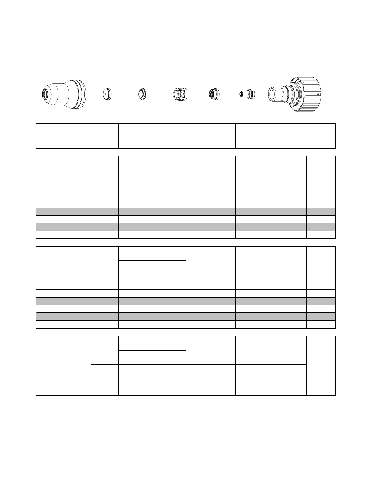
Stainless Steel
2
150A
Plasma / H2O Shield
N
2
Shield Cup
Shield Cap
Shield Gas
Distributor
Tip
Plasma Gas
Distributor
Electrode
Cartridge
This Art Is For Reference ONLY
Shield Cup Shield Cap
22-1016
Mate ri al
Thickn es s
(ga) (in) inch (PSI) (Ball) (PSI) (Ball) (PSI) Volts
1/4 0.250 70 60 90 8 55 135 0.100 110 0.250 0.3 0.104
3/8 0.375 70 60 90 8 55 139 0.100 70 0.350 0.3 0.107
1/2 0.500 70 60 90 8 55 149 0.150 60 0.350 0.5 0.111
5/8 0.625 70 60 90 8 55 159 0.180 45 0.350 0.5 0.128
3/4 0.750 70 60 90 4 55 159 0.180 40 0.350 0.9 0.130
Mate ri al
Thickn es s
(mm)
8.0
10.0
12.0
15.0
20.0
17A Arc Cur r e nt
Burn-through
may occur
for th ickn es s es
< 1/16" (0.063") / 1.6
mm.
BOLD TYPE
22-1048 22-1278 22-1092 22-1041 22-1081 22-1020
Pre Flow
Pressure
(Air)
Pre Flow
Pressure
(Air)
(Bar) (Ball) (Bar) (Ball) (Bar) Volts
4.8 60 6.2 8 3.8 137.0 2.5 2265 6.4 0.3 2.7
4.8 60 6.2 8 3.8 140.0 2.5 1740 8.9 0.3 2.7
4.8 60 6.2 8 3.8 147.5 3.8 1580 8.9 0.5 2.8
4.8 60 6.2 8 3.8 156.2 4.6 1248 8.9 0.5 3.2
4.8 60 6.2 4 3.8 162.0 4.6 1010 8.9 0.9 3.3
Pre Flow
Pressure
(N
(PSI) /
(Bar)
20 60 80 0.120 300 0.120
1.4 4.1 5.5 3.0 7600 3.0
indicates maximum piercing parameters.
Shield Gas
Distributor
Plas m a (N
Plas m a (N
)
2
(Ball)
60 75
Tip
Cut Flow Rate s /
Pressures
Shield
)
2
(H
O)*
2
Cut Flow Rate s /
Pressures Arc
Shield
)
2
(H
O)*
Marking
Cut Flow Rate s /
Pressures Arc
) Shield (N2)
2
(PSI) /
(Bar)
(Ball)
(PSI) /
(Bar)
Plasma Gas
Distributor
Arc
Vol tag e
Vol tag e
Vol tag e
Vol ts
130 0
Torch
Working
Height
(in)
±0.005
Torch
Working
Height
(mm)
±0.1
Torch
Working
Height
in ±0.005 /
mm ±0. 1
Travel
Speed
(ipm ) (in) (s ec) (in)
Travel
Speed
( mm/mi n)
Travel
Speed
ipm /
mm/min
Art # A-07958_AB
Electrode Cartridge
Initial
Piercing
Height
Initial
Piercing
Height
(mm) (sec) (mm)
Initial
Tran s fer
Height
in ±0.005 /
mm ±0.1
Pierce
Delay
Pierce
Delay
Pierce
Delay
(sec)
Kerf Width
@ Rec.
SpeedPlas m a (N
Kerf Width
@ Rec.
Speed
Mar ki ng
quality
degrades
as
thi ckn es s
decreases
Manual 0-4829 Rev AN 8-43 TORCH DATA for Ultra-Cut
Page 42
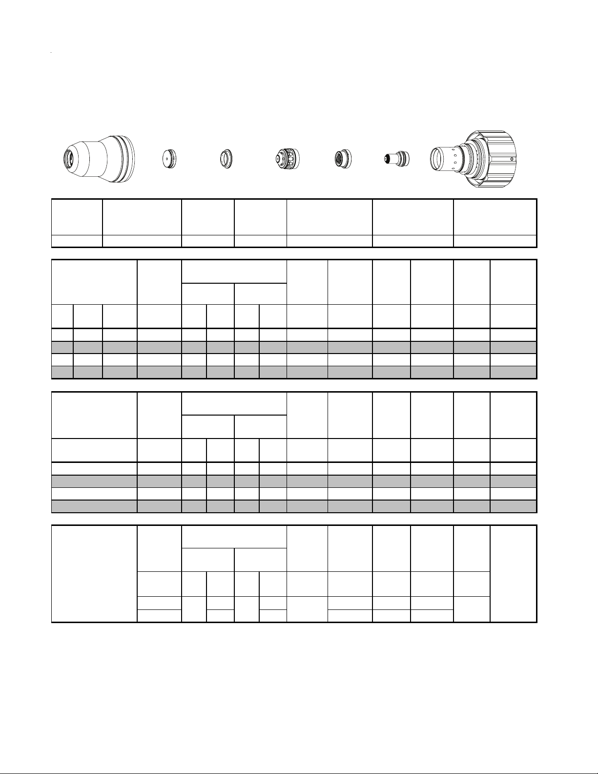
Aluminum
150A
H35 Plasma / N
Shield Cup
22-1016 22-1037 22-1081 22-1020
Mate ri al
Thickness
(ga) (in) inch psi Ball psi Ball psi Volts
1/2 0.500 70 80 120 60 120 167 0.400 75 0.450 0.4 0.120
5/8 0.625 70 80 120 60 120 165 0.300 40 0.350 0.5 0.129
3/4 0.750 70 80 120 60 120 173 0.300 35 0.400 0.8 0.139
1 1.000 70 80 120 60 120 175 0.300 25 0.450 1.8 0.137
Shield
2
Shield Cap
Pre Flow
Pressure
(N
)
2
Shield Gas
Distributor
Tip
This Art Is For Reference ONLY
Shield Gas
Distributor
22-1278 22-1063
Cut Flow Ra tes /
Pressures
Plas m a
(H35)
Tip
Shield (N
)
2
Plasma Gas
Distributor
Plasma Gas
Distributor
22-1041
Arc
Vol tag e
Torch
Working
Height
(in)
±0.005
Electrode
Cartridge
Art # A-07958_AB
Elec trode CartridgeShield Cup Shield Cap
Travel
Speed
(ipm ) (in) (s ec) (in)
Initial
Piercing
Height
Pierce
Delay
Kerf Width
@ Rec.
Speed
Mate ri al
Thickness
(mm )
12
15
20
25
19A Arc Current
Burn-through
may occur
for thicknesses
< 1/16" (0.063") / 1.6
mm.
BOLD TYPE
indicates maximum piercing parameters.
Pre Flow
Pressure
)
(N
2
bar Ball bar Ball bar Volts
4.8 80 8.3 60 8.3 167 10.2 2100 11.4 0.4 3.0
4.8 80 8.3 60 8.3 165 7.6 1260 8.9 0.5 3.2
4.8 80 8.3 60 8.3 173 7.6 850 10.2 0.8 3.5
4.8 80 8.3 60 8.3 175 7.6 650 11.4 1.8 3.5
Pre Flow
Pressure
(N
)
2
(PSI) /
(Bar)
20 60 80 0.120 300 0.120
1.4 4.1 5.5 3.0 7600 3.0
Cut Flow Ra tes /
Vol tag e
)
2
Marking
Vol tag e
Vo lt s
Arc
Pressures
Plas m a
(H35)
Cut Flow Ra tes /
Plas m a (N
(PSI) /
(Ball)
60 75 130 0
Shield (N
Pressures Arc
) Shield (N2)
2
(PSI) /
(Ball)
(Bar)
(Bar)
Torch
Working
Height
(mm )
±0.1
Torch
Working
Height
in ±0.005 /
mm ±0. 1
Travel
Speed
( mm/mi n)
Travel
Speed
ipm /
mm/min
Initial
Piercing
Height
(mm ) (s ec) (m m )
Initial
Transfer
Height
in ±0.005 /
mm ±0.1
Pierce
Delay
Pierce
Delay
(sec)
Kerf Width
@ Rec.
Speed
Mar ki ng
quality
degrades
as
thickn es s
decreases
TORCH DATA for Ultra-Cut 8-44 Manual 0-4829 Rev AN
Page 43

2
2
Aluminum
150A
N
Plasma / H2O Shield
2
Shield Cup
Shield Cap
Shield Gas
Distributor
Tip
This Art Is For Reference ONLY
Shield Cup Shield Cap
22-1016
Mate ri al
Thickn es s
(ga) (in) inch (PSI) (Ball) (PSI) (Ball) (PSI) Volts
3/16 0.188 70 60 90 8 55 130 0.100 150 0.350 0.2 0.107
1/4 0.250 70 60 90 8 55 133 0.120 120 0.350 0.2 0.108
3/8 0.375 70 60 90 8 55 140 0.120 100 0.350 0.2 0.116
1/2 0.500 70 60 90 8 55 152 0.200 75 0.350 0.3 0.126
5/8 0.625 70 60 90 8 55 155 0.200 50 0.350 0.4 0.142
3/4 0.750 70 60 90 8 55 165 0.250 35 0.350 0.5 0.141
1 1.000 70 60 90 8 55 178 0.300 20 0.350 1.0 0.155
22-1048 22-1278 22-1092 22-1041 22-1081 22-1020
Pre Flow
Pressure
(Air)
Shield Gas
Distributor
Cut Flow Rate s /
Pressures
2
Tip
Shield
)
(H
O)*
Plasma Gas
Distributor
Plasma Gas
Distributor
Arc
Vol tag e
Torch
Working
Height
(in)
±0.005
Electrode
Cartridge
Art # A-07958_AB
Electrode Cartridge
Travel
Speed
(ipm ) (in) (s ec) (in)
Initial
Piercing
Height
Pierce
Delay
Kerf Width
@ Rec.
SpeedPlas m a (N
Mate ri al
Thickn es s
(mm)
5
6
8
10
12
15
20
25
17A Arc Cur r e nt
Burn-through
may occur
for th ickn es s es
< 1/16" (0.063") / 1.6
mm.
BOLD TYPE
indicates maximum piercing parameters.
Pre Flow
Pressure
(Air)
(Bar) (Ball) (Bar) (Ball) (Bar) Volts
4.8 60 6.2 8 3.8 130 2.5 3700 8.9 0.2 2.7
4.8 60 6.2 8 3.8 132 3.0 3220 8.9 0.2 2.7
4.8 60 6.2 8 3.8 137 3.0 2785 8.9 0.2 2.8
4.8 60 6.2 8 3.8 142 3.0 2445 8.9 0.2 2.9
4.8 60 6.2 8 3.8 149 5.1 2050 8.9 0.3 3.2
4.8 60 6.2 8 3.8 154 5.1 1445 8.9 0.4 3.4
4.8 60 6.2 8 3.8 167 6.4 830 8.9 0.5 3.7
4.8 60 6.2 8 3.8 177 7.6 535 8.9 1.0 3.9
Pre Flow
Pressure
)
(N
2
(PSI) /
(Bar)
20 60 80 0.120 300 0.120
1.4 4.1 5.5 3.0 7600 3.0
Cut Flow Rate s /
Pressures Arc
Plas m a (N
Plas m a (N
(Ball)
60 75
)
2
Cut Flow Rate s /
Pressures Arc
) Shield (N2)
2
(PSI) /
(Bar)
Shield
(H
(Ball)
O)*
Marking
(PSI) /
(Bar)
Torch
Vol tag e
Vol tag e
Vol ts
130 0
Working
Height
(mm)
±0.1
Torch
Working
Height
in ±0.005 /
mm ±0. 1
Travel
Speed
( mm/mi n)
Travel
Speed
ipm /
mm/min
Initial
Piercing
Height
(mm) (sec) (mm)
Initial
Tran s fer
Height
in ±0.005 /
mm ±0.1
Pierce
Delay
Pierce
Delay
(sec)
Kerf Width
@ Rec.
Speed
Mar ki ng
quality
degrades
as
thi ckn es s
decreases
Manual 0-4829 Rev AN 8-45 TORCH DATA for Ultra-Cut
Page 44

Mild Steel
200A
Plasma / Air Shield
O
2
Shield Retainer
Shield
Shield Gas
Distributor
Tip
Plasma Gas
Distributor
Electrode
Cartridge
Initial
Piercing
Hei gh t
Edge Start
Edge Start
Initial
Piercing
Hei gh t
Initial
Hei gh t
Art # A-07917_AC
22-102222-1014 22-1030 22-1285 22-1055
Pie r c e
Del ay
Pie r c e
Del ay
Pie r c e
Del ay
(sec)
0
Kerf Width
Kerf Width
degrades
thickness
decreas es
This Art Is For Reference ONLY
Shield
Ret ai ner
Ma te ri al
Thickness
(ga) (in) inch (PSI) ( Ball) (PSI) ( Ball) (PSI) V olts
3/16 0.188 15 100 100 NA 100 151 0.130 250 0.300 0.2 0.142
1/4 0.250 15 100 100 NA 100 151 0.130 200 0.300 0.2 0.148
3/8 0.375 15 100 100 NA 100 154 0.150 140 0.350 0.3 0.162
1/2 0.500 15 100 100 NA 100 159 0.170 115 0.350 0.5 0.167
5/8 0.625 15 100 100 NA 100 161 0.200 80 0.350 0.6 0.186
3/4 0.750 15 100 100 NA 100 163 0.200 65 0.400 0.8 0.186
7/8 0.875 15 100 100 NA 100 166 0.200 57 0.400 1.0 0.185
1 1.000 15 100 100 NA 100 167 0.200 48 0.400 1.2 0.193
1 1/4 1.250 15 100 100 NA 100 170 0.200 30 0.425 2.0 0.196
1 1/2 1.500 15 100 100
2 2.000 15 100 100
2 1/2 2.500 15 100 100
Ma te ri al
Thickness
( mm)
10
12
15
20
25
32
38
44 Edge Start
50 Edge Start
60 Edge Start
25A Arc Cur rent
BOLD TYPE
Requires CCM version 3.4 or later. Requires GCM version 3.2 or later
Lock pierce height betw een 0.5" to 1" to avoid torch hitting the pierce metal puddle.
NOT E:
Shield Cap
Pre Flow
Pr e s s ur e
(Air)
Pre Flow
Pr e s s ur e
(Air)
(Bar ) (Ball) (Bar) (Ball) (Ba r) V olts
5
6
8
indicates maximum pierc ing parameters.
1.0 100 6.9 NA 6.9 151 3.3 6170 7.6 0.2 3.6
1.0 100 6.9 NA 6.9 151 3.3 5360 7.6 0.2 3.7
1.0 100 6.9 NA 6.9 153 3.6 4290 8.3 0.3 3.9
1.0 100 6.9 NA 6.9 155 3.9 3460 8.9 0.3 4.1
1.0 100 6.9 NA 6.9 158 4.2 3060 8.9 0.5 4.2
1.0 100 6.9 NA 6.9 160 4.0 2280 8.9 0.6 4.6
1.0 100 6.9 NA 6.9 164 5.1 1590 10.2 0.9 4.7
1.0 100 6.9 NA 6.9 167 5.1 1250 10.2 1.2 4.9
1.0 100 6.9 NA 6.9 171 5.1 750 10.8 2.1 5.0
1.0 100 6.9 NA 6.9 185 5.1 510 11.4 4.0 5.1
1.0 100 6.9
1.0 100 6.9
1.0 100 6.9
Pre Flow
Pr e s s ur e
(N
(PSI) /
(Bar)
15 60 80 0.120 300 0.120
1.0 4.1 5.5 3.0 7600 3.0
Shield Gas
Distributor
Cut Flow Rates / Pressures
Pla s ma ( O
Cut Flow Rates / Pressures
Pla s ma ( O
Cut Flow Rates / Pressures
)
Pla s ma ( N
2
(Ball)
80 NA 168
) Shield (Air)
2
NA
NA
NA
) Shield (Air)
2
NA
NA
NA
) Shield (N2)
2
(PSI) /
(Ball)
(Bar)
BOLD ITALIC
Tip
100 185 0.200 20 0.450 4.0 0.201
100 192 0.200 10 0.204
100 192 0.200 8 0.210
6.9 188 5.1 390 5.1
6.9 192 5.1 270 5.2
6.9 192 5.1 200 5.3
Marking
(PSI) /
(Bar)
Pla s ma G a s
Dis tr ibut or
22-1042 22-1093
Arc
Voltage
Arc
Voltage
Arc
Voltage
Volts
indicates edge starts only.
Tor c h
Working
Height
(in)
±0.005
Tor c h
Working
Height
( mm)
±0.1
Tor c h
Working
Height
in ±0.005 /
mm ±0.1
(mm/min) (mm) (sec) (mm)
mm/mi n
Electrode Cartridge
Trav el
Speed
(ipm) (in) (sec) (in)
Trav el
Speed
Trav el
Speed
ipm /
Transf er
in ±0.005 /
mm ±0.1
@ Rec.
Speed
@ Rec.
Speed
Ma r kin g
quality
as
TORCH DATA for Ultra-Cut 8-46 Manual 0-4829 Rev AN
Page 45

Edge
Stainless Steel
200A
H35 Plasma / N
Shield Retainer
Shield
Retainer
Ma teri al
Thicknes s
(ga) (in) inch (PSI) (Ball) (PSI)
3/8 0.375 20 120 100 NA 120 168 0.300 90 0.400 0.4 0.131
1/2 0.500 20 120 100 NA 120 170 0.300 65 0.400 0.5 0.135
5/8 0.625 20 120 100 NA 100 173 0.300 50 0.350 0.6 0.142
3/4 0.750 20 120 100 NA 100 175 0.300 40 0.400 0.8 0.143
7/8 0.875 20 120 100 NA 100 178 0.300 35 0.450 1.0 0.148
1 1.000 20 120 100 NA 120 184 0.350 30 0.450 1.0 0.162
1 1/4 1.250 20 120 100 NA 120 185 0.350 20 0.170
1 1/2 1.500 20 120 100 NA 120 190 0.350 16 0.175
2 2.000 20 120 100 NA 120 193 0.350 12 0.182
Shield Cap
Shield
2
Shield
Pre Flow
Pressure
(N
)
2
Shield Gas
Distributor
Tip
This Art Is For Reference ONLY
Shield Gas
Distributor
Cu t Flow R ates /
Pressures Arc
Plasma (H35)
Tip
Shield (N2)
(PSI) Volts
(Ball)
Plasma Gas
Distributor
Electrode
Plasma Gas
Distributor
22-1042 22-1096
Torch
Vo lt ag e
Working
Height
(in)
±0.005
Speed
Cartridge
Art # A-07917_AC
Elec trode Cartridge
22-102222-1015 22-1073 22-1284 22-1095
Travel
(ipm ) (in) (sec) (in)
Initial
Piercing
Height
Pierce
Delay
Edge Start
Edge Start
Edge Start
Kerf Width
@ Rec.
Speed
Ma teri al
Thicknes s
(mm)
10
12
15
20
25
32
38
44 Edge Start
50 Edge Start
20A Arc Current
BOLD TYPE
Requires CCM version 3.4 or later. Requires GCM version 3.2 or later
NOTE:
indicates m aximum piercing parameters.
Lock pierce height between 0.5" to 1" to avoid torch hitting the pierce metal puddle.
Pre Flow
Pressure
(Air)
(Bar) (Ball) (Bar)
1.4 120 6.9 NA 8.3 168 7.6 2200 10.2 0.3 3.4
1.4 120 6.9 NA 8.3 170 7.6 1700 10.2 0.5 3.4
1.4 120 6.9 NA 6.9 172 7.6 1300 8.9 0.6 3.6
1.4 120 6.9 NA 6.9 176 7.6 950 10.2 0.9 3.7
1.4 120 6.9 NA 8.3 183 8.9 770 11.4 1.2 4.0
1.4 120 6.9 NA 8.3 186 8.9 500
1.4 120 6.9
1.4 120 6.9
1.4 120 6.9
Pre Flow
Pressure
(N
)
2
(PSI) /
(Bar)
15 60 80 0.120 300 0.120
1.0 4.1 5.5 3.0 7600 3.0
Cu t Flow R ates /
Pressures
Plas m a (O
Plas m a (N
(Ball)
80 NA
) Shield (Air)
2
Cu t Flow R ates /
Pressures Arc
) Shield (N2)
2
(PSI) /
(Bar)
Arc
Vo lt ag e
(Ball)
(Bar) Volts
NA
8.3 190 8.9 400
NA
8.3 192 8.9 340 4.5
NA
8.3 193 8.9 300 4.6
Marking
Vo lt ag e
(PSI) /
(Ball)
(Bar)
BOLD ITA LIC
Vol ts
140 0
Torch
Working
Height
(mm)
±0.1
Torch
Working
Height
in ±0.005 /
mm ±0.1
indicates edge starts only.
Travel
Speed
( mm/min )
Travel
Speed
ipm /
mm/ min
Initial
Piercing
Height
(mm) (sec) (mm)
Edge
Start
Initial
Trans fer
Height
in ±0.005 /
mm ±0 . 1
Pierce
Delay
Pierce
Delay
Kerf Width
@ Rec.
Speed
0.0 4.3
0.0 4.4
Ma rki ng
quality
degrades
(sec)
thickness
decreases
as
Manual 0-4829 Rev AN 8-47 TORCH DATA for Ultra-Cut
Page 46
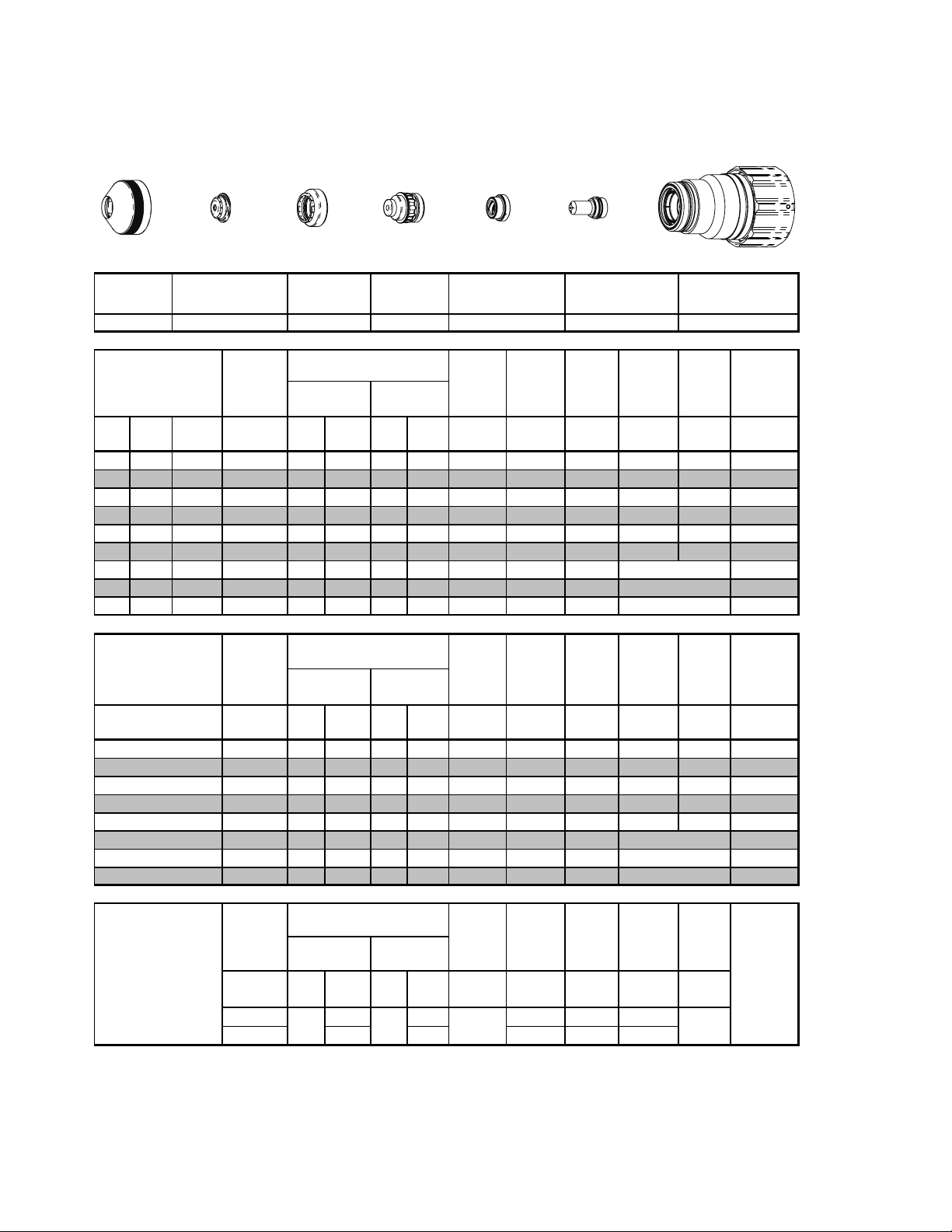
Stainless Steel
200A
Plasma / H2O Shield
N
2
Shield Retainer
Shield
Shield Gas
Distributor
Tip
Plasma Gas
Distributor
Electrode
Cartridge
This Art Is For Reference ONLY
Shield
Retainer
Mate ri al
Thickness
(ga) (in) inch (PSI) (Ball) (PSI) (Ball) (PSI) Volts
3/8 0.375 20 80 90 5 55 155 0.160 95 0.300 0.0 0.110
1/2 0.500 20 80 90 5 55 156 0.160 85 0.300 0.4 0.115
5/8 0.625 20 80 90 5 55 158 0.180 65 0.300 0.5 0.122
3/4 0.750 20 80 90 5 55 163 0.200 50 0.300 0.7 0.133
7/8 0.875 20 80 90 5 55 177 0.250 40 0.400 0.9 0.149
1 1.000 20 80 90 5 55 183 0.300 35 0.450 1.0 0.148
1 1/4 1.250 20 80 90 5 55 185 0.300 20 0.176
1 1/2 1.500 20 80 90 5 55 200 0.350 10 0.211
1 3/4 1.750 20 80 90 5 55 207 0.350 8 0.216
Mate ri al
Thickness
(mm)
20A Arc Current
BOLD TYPE
Requires CCM version 3.4 or later. Requires GCM version 3.2 or later.
* Pressure of the water supply line should be regulated by customer pressure regulator.
Ohmic height sensing is not recommended with water shield. Water on the plate interferes electrically with the
Note1:
ohmic sensing circuit.
Water source used for shield must be demineralized.
Note2:
Shield Cap
Pre Flow
Pressure
(N
Pre Flow
Pressure
(N
(Bar) (Ball) (Bar) (Ball) (Bar) Volts
10
12
15
20
25
32
38
44
indicates maximum piercing parameters.
1.4 80 6.3 5 3.8 155 4.1 2400 7.6 0.0 2.8
1.4 80 6.3 5 3.8 156 4.1 2000 7.6 0.4 2.9
1.4 80 6.3 5 3.8 157 4.4 1550 7.6 0.5 3.1
1.4 80 6.3 5 3.8 165 5.1 1100 7.6 0.7 3.4
1.4 80 6.3 5 3.8 183 7.6 900 11.4 0.9 3.7
1.4 80 6.3 5 3.8 185 7.6 500 4.5
1.4 80 6.3 5 3.8 200 8.9 250 5.4
1.4 80 6.3 5 3.8 206 8.9 200 5.5
Pre Flow
Pressure
(N
(PSI) /
(Bar)
1.0 4.1 5.5 3.0 7600 3.0
Shield Gas
Distributor
Cu t Flow Rates /
Pressures Arc
Plas m a (N
)
2
Cu t Flow Rates /
Pressures Arc
)
2
Cu t Flow Rates /
Pressures Arc
Plas m a (N
)
2
(PSI) /
(Ball)
(Bar)
15 60 80 0.120 300 0.120
80 NA
Tip
Shield
)
2
)
2
) Shield (N2)
2
(H
Shield
(H
(Ball)
O)*
2
O)*
2
(PSI) /
(Bar)
BOLD ITALIC
Plasma Gas
Distributor
22-1043 22-1089 22- 102222-1015 22-1049 22-1284 22- 1067
Torch
Voltage
Voltage
Marking
Voltage
Vo lts
Workin g
Height
(in)
±0.005
Torch
Workin g
Height
(mm)
±0.1
Torch
Workin g
Height
in ±0.005 /
mm ±0.1
140 0
indicates edge starts only.
Electrode Cartridge
Travel
Speed
(ipm ) (in) (s ec) (in)
Travel
Speed
( mm/mi n)
Travel
Speed
ipm /
mm/ mi n
in ±0.005 /
Art # A-07917_AC
Initial
Piercing
Height
Initial
Piercing
Height
(mm) (sec) (mm)
Initial
Transfer
Height
mm ±0.1
Pierce
Delay
Edge Sta rt
Edge Sta rt
Edge Sta rt
Pierce
Delay
Edge Sta rt
Edge Sta rt
Edge Sta rt
Pierce
Delay
(sec)
Kerf Width
Kerf Width
degrades
thickness
decreases
@ Rec.
Speed
@ Rec.
SpeedPlas m a (N
Markin g
quality
as
TORCH DATA for Ultra-Cut 8-48 Manual 0-4829 Rev AN
Page 47

Edge
Aluminum
C
200A
H35 Plasma / N
Shield Retainer
Shield
Retainer
Ma teri al
Thicknes s
(ga) (in) inch (PSI) (Ball) (PSI)
Shield Cap
< 1" / 25mm 22-1073
1" / 25mm + 22-1094
Shield
2
Shield Cap
Pre Flow
Pres s ure
)
(N
2
Shield Gas
Distributor
This Art Is For Reference ONLY
Shield Gas
Distributor
22-1284 22- 1095
ut Flow Rates /
Pressures Arc
Plasma (H35)
Shield (N2)
(Ball)
Tip
Tip
(PSI) Volts
Plasma Gas
Distributor
Electrode
Plasma Gas
Distributor
22-1043 22-1096
Torch
Vol tage
Worki ng
Height
±0.005
Speed
(in)
Cartridge Assembly
Art # A-08567
Electrode Cartridge
22-102222-1015
Travel
Initial
Piercing
Pierce
Height
(ipm ) (in) (s ec) (in)
Kerf Width
Delay
3/8 0.375 20 100 100 NA 110 165 0.300 180 0.400 0.4 0.113
1/2 0.500 20 100 100 NA 110 168 0.300 150 0.350 0.2 0.119
5/8 0.625 20 100 100 NA 110 170 0.300 110 0.350 0.3 0.120
3/4 0.750 20 100 100 NA 110 172 0.300 70 0.400 0.4 0.130
7/8 0.875 20 100 100 NA 110 178 0.350 55 0.450 0.5 0.139
1 1.000 20 100 100 NA 110 180 0.350 40 0.500 0.7 0.150
1 1/4 1.250 20 100 100 NA 110 185 0.400 32 0.161
1 1/2 1.500 20 100 100 NA 110 195 0.400 25 0.170
2 2.000 20 100 100 NA 110 201 0.400 15 0.205
Edge Star t
Edge Star t
Edge Star t
@ Rec.
Speed
Ma teri al
Thicknes s
(mm)
10
12
15
20
25
32
38
44 Edge Star t
50 Edge Star t
Pre Flow
Pres s ure
(Air)
(Bar) (Ball) (Bar)
1.4 100 6.9 NA 7.6 166 7.6 4500 10.2 0.4 2.9
1.4 100 6.9 NA 7.6 168 7.6 3850 8.9 0.2 3.0
1.4 100 6.9 NA 7.6 170 7.6 2800 8.9 0.3 3.0
1.4 100 6.9 NA 7.6 174 7.6 1600 10.2 0.5 3.3
1.4 100 6.9 NA 7.6 180 8.9 1050 12.7 0.7 3.8
1.4 100 6.9 NA 7.6 185 10.2 800
1.4 100 6.9
1.4 100 6.9
1.4 100 6.9
Cut Flo w Ra tes /
Pressures
Plas ma (O
) Shield (Air)
2
(Ball)
(Bar) Volts
NA
7.6 195 10.2 640
NA
7.6 198 10.2 450 4.8
NA
7.6 200 10.2 380 5.2
Arc
Vol tage
Torch
Worki ng
Height
(mm)
±0.1
Marking
20 A Ar c Cur rent
BOLD TYPE
indicates m aximum piercing parameters.
Pre Flow
Pres s ure
)
(N
2
(PSI) /
(Bar)
15 60 80 0.120 300 0.120
1.0 4.1 5.5 3.0 7600 3.0
Cut Flo w Ra tes /
Pressures Arc
Plas ma (N
(Ball)
) Shield (N2)
2
(PSI) /
(Bar)
(Ball)
80 NA
Vol tage
(PSI) /
(Bar)
Vol ts
140 0
BOLD ITALIC
Torch
Worki ng
Height
in ±0.005 /
mm ±0.1
indicates edge starts only.
Requires CCM version 3.4 or later. Requires GCM version 3.2 or later
Lock pierce height between 0.5" to 1" to avoid torch hitting the pierce metal puddle.
NOTE:
Travel
Speed
(mm/min)
Travel
Speed
ipm /
mm/ min
Initial
Piercing
Height
Pierce
Delay
Kerf Width
@ Rec.
Speed
(mm ) (sec) (mm)
0.0 4.1
Edge
Start
Initial
Transfer
Height
in ±0.005 /
mm ±0 . 1
0.0 4.3
Pierce
Delay
degrades
(sec)
thickness
Ma rki ng
quality
decreases
as
Manual 0-4829 Rev AN 8-49 TORCH DATA for Ultra-Cut
Page 48

C
Aluminum
200A
Plasma / H2O Shield
N
2
Shield Retainer
Shield
Shield Gas
Distributor
Tip
Plasma Gas
Distributor
Electrode
Cartridge
This Art Is For Reference ONLY
Shield
Retainer
Materi al
Thi cknes s
(ga) (in) inch (PSI) (Ball) (PSI) (Ball) (PSI) Volts
1/2 0.500 20 100 90 5 55 168 0.250 110 0.300 0.3 0.120
5/8 0.625 20 80 100 5 55 170 0.300 105 0.350 0.5 0.126
3/4 0.750 20 80 100 5 55 175 0.300 90 0.350 0.6 0.127
7/8 0.875 20 80 100 5 55 180 0.300 75 0.350 0.8 0.133
1 1.000 20 80 100 5 55 194 0.350 50 0.400 1.0 0.144
1 1/4 1.250 20 80 100 5 55 208 0.400 25 0.450 2.0 0.180
1 1/2 1.500 20 80 100 5 55 210 0.400 20 0.500 3.000 0.197
1 3/4 1.750 20 80 100 5 55 212 0.400 18 0.201
2 2.000 20 80 100 5 55 215 0.400 12 0.204
Materi al
Thi cknes s
(mm )
44
50
20A Arc Current
BOLD TYPE
Requires CCM version 3.4 or later. Requires GCM version 3.2 or later.
* Pressure of the water supply line s hould be regulated by customer pressure regulator.
Ohmic height sens ing is not recommended with water shield. Water on the plate interferes electrically with the
Note 1:
ohmic sensing circuit.
Water source used for shield mus t be demineralized.
Note 2:
Shield Cap
Pre Flow
Press ure
(N
Pre Flow
Press ure
(N
(Bar) (Ball) (Bar) (Ball) (Bar) Volts
12
15
20
25
32
38
indicates maximum piercing parameters.
1.4 100 6.3 5 3.8 167 6.3 2900 7.6 0.3 3.0
1.4 80 6.9 5 3.8 170 7.5 270 0 8.9 0 .5 3.2
1.4 80 6.9 5 3.8 176 7.5 220 0 8.9 0 .6 3.3
1.4 80 6.9 5 3.8 194 8.9 1300 10.2 1.0 3.6
1.4 80 6.9 5 3.8 208 10.2 630 11.4 2.0 4.6
1.4 80 6.9 5 3.8 210 10.2 500 12.7 3.0 5.0
1.4 80 6.9 5 3.8 212 10.2 460 5.1
1.4 80 6.9 5 3.8 215 10.2 300 5.2
Pre Flow
Press ure
(N
(PSI) /
(Bar)
15 60 80 0.120 300 0.120
1.0 4.1 5.5 3.0 7600 3.0
Shield Gas
Distribut or
Plasma (N
)
2
Plasma (N
)
2
Plasma (N
)
2
(Ball)
80 NA
Tip
Cut Flow R ates /
Press ures Arc
ut Flow Rates /
Press ures
Cut Flow R ates /
Press ures Arc
(PSI) /
(Bar)
Shield
)
2
)
2
) Shield (N2)
2
(H
Shield
(H
(Ball)
O)*
2
O)*
2
(PSI) /
(Bar)
BOLD ITALIC
Plasma Gas
Distribut or
22-1043 22-1089 22- 102222-1015 22-1049 22-1284 22-1067
Torch
Vo lta ge
Vo lta ge
Marking
Vo lta ge
Volts
Working
Height
(in)
±0.005
Arc
140 0
Torch
Working
Height
(mm)
±0.1
Torch
Working
Height
in ±0.005 /
mm ±0 . 1
indicates edge s tarts only.
Elect rode Cartridge
Travel
Speed
(ipm ) (in) (s ec) (in)
Travel
Speed
( mm/mi n)
Travel
Speed
ipm /
mm/ min
Piercing
Piercing
Transfer
in ±0.005 /
Art # A-07917_AC
Initial
Height
Initial
Height
(mm) (sec) (mm)
Initial
Height
mm ±0 . 1
Pierce
Delay
Edge Start
Edge Start
Pierce
Delay
Edge Start
Edge Start
Pierce
Delay
(sec)
Kerf Width
Kerf Width
degrades
thi ckne s s
decreases
@ Rec.
Speed
@ Rec.
Speed
Marki ng
quality
as
TORCH DATA for Ultra-Cut 8-50 Manual 0-4829 Rev AN
Page 49
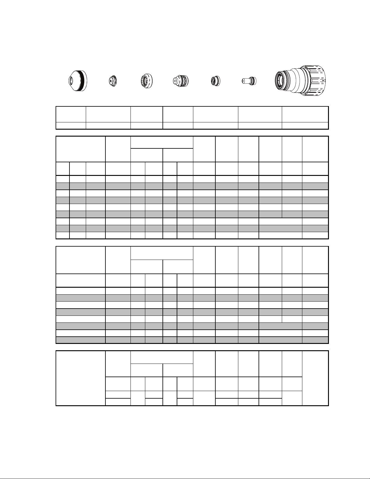
Stainless Steel
200A
Plasma / H2O Shield
N
2
Shield Retainer
Shield
Shield Gas
Distributor
Tip
Plasma Gas
Distributor
Electrode
Cartridge
Initial
Height
Edge Start
Edge Start
Edge Start
Initial
Height
Edge Start
Edge Start
Edge Start
Initial
Height
mm ±0.1
Art # A-07917_AC
Pierce
Delay
Pierce
Delay
Pierce
Delay
(sec)
Kerf Width
Kerf Width
degrades
thickness
decreases
This Art Is For Reference ONLY
Shield
Retainer
Mate ri al
Thickness
(ga) (in) inch (PSI) (Ball) (PSI) (Ball) (PSI) Volts
3/8 0.375 20 80 90 5 55 155 0.160 95 0.300 0.0 0.110
1/2 0.500 20 80 90 5 55 156 0.160 85 0.300 0.4 0.115
5/8 0.625 20 80 90 5 55 158 0.180 65 0.300 0.5 0.122
3/4 0.750 20 80 90 5 55 163 0.200 50 0.300 0.7 0.133
7/8 0.875 20 80 90 5 55 177 0.250 40 0.400 0.9 0.149
1 1.000 20 80 90 5 55 183 0.300 35 0.450 1.0 0.148
1 1/4 1.250 20 80 90 5 55 185 0.300 20 0.176
1 1/2 1.500 20 80 90 5 55 200 0.350 10 0.211
1 3/4 1.750 20 80 90 5 55 207 0.350 8 0.216
Mate ri al
Thickness
(mm)
20 A Ar c Cur r e nt
BOLD TYPE
Requires CCM version 3.4 or later. Requires GCM version 3.2 or later.
* Pressure of the water supply line should be regulated by customer pressure regulator.
Ohmic height sensing is not recommended with water shield. Water on the plate interferes electrically with the
Note 1 :
ohmic sensing circuit.
Water source used for shield must be demineralized.
Note 2 :
Shield Cap
Pre Flow
Pressure
(N
Pre Flow
Pressure
(N
(Bar) (Ball) (Bar) (Ball) (Bar) Volts
10
12
15
20
25
32
38
44
indicate s maxim um piercing param eters.
1.4 80 6.3 5 3.8 155 4.1 2400 7.6 0.0 2.8
1.4 80 6.3 5 3.8 156 4.1 2000 7.6 0.4 2.9
1.4 80 6.3 5 3.8 157 4.4 1550 7.6 0.5 3.1
1.4 80 6.3 5 3.8 165 5.1 1100 7.6 0.7 3.4
1.4 80 6.3 5 3.8 183 7.6 900 11.4 0.9 3.7
1.4 80 6.3 5 3.8 185 7.6 500 4.5
1.4 80 6.3 5 3.8 200 8.9 250 5.4
1.4 80 6.3 5 3.8 206 8.9 200 5.5
Pre Flow
Pressure
(N
(PSI) /
(Bar)
15 60 80 0.120 300 0.120
1.0 4.1 5.5 3.0 7600 3.0
Shield Gas
Distributor
Plas ma (N
)
2
)
2
Plas ma (N
)
2
(Ball)
80 NA
Tip
Cu t Flow Rate s /
Pressures Arc
Cu t Flow Rate s /
Pressures Arc
Cu t Flow Rate s /
Pressures Arc
(PSI) /
(Bar)
Shield
)
2
(H
O)*
2
Shield
)
2
) Shield (N2)
2
(H
(Ball)
O)*
2
(PSI) /
(Bar)
BOLD ITALIC
Plasma Gas
Distributor
22-1043 22-1089 22-102222-1015 22-1049 22-1284 22- 1067
Torch
Voltage
Voltage
Marking
Voltage
Vol ts
Working
Height
(in)
±0.005
Torch
Working
Height
(mm )
±0.1
Torch
Working
Height
in ±0.005 /
mm ±0.1
140 0
indicates edge starts only.
Elec trode Cartridge
Travel
Speed
(ipm ) (in) (sec) (in)
Travel
Speed
(mm/min) (mm) (sec) (mm)
Travel
Speed
ipm /
mm/mi n
Piercing
Piercing
Transfer
in ±0.005 /
@ Rec.
Speed
@ Rec.
SpeedPlas ma (N
Markin g
quality
as
Manual 0-4829 Rev AN 8-51 TORCH DATA for Ultra-Cut
Page 50

This Page Intentionally Blank
TORCH DATA for Ultra-Cut 8-52 Manual 0-4829 Rev AN
Page 51

Insert "150-200 Amp
Bevel Cutting" Tab.
Discard this sheet.
Manual 0-4829 Rev AN 8-53 TORCH DATA for Ultra-Cut
TAB SHEET
Page 52

TORCH DATA for Ultra-Cut 8-54 Manual 0-4829 Rev AN
Page 53
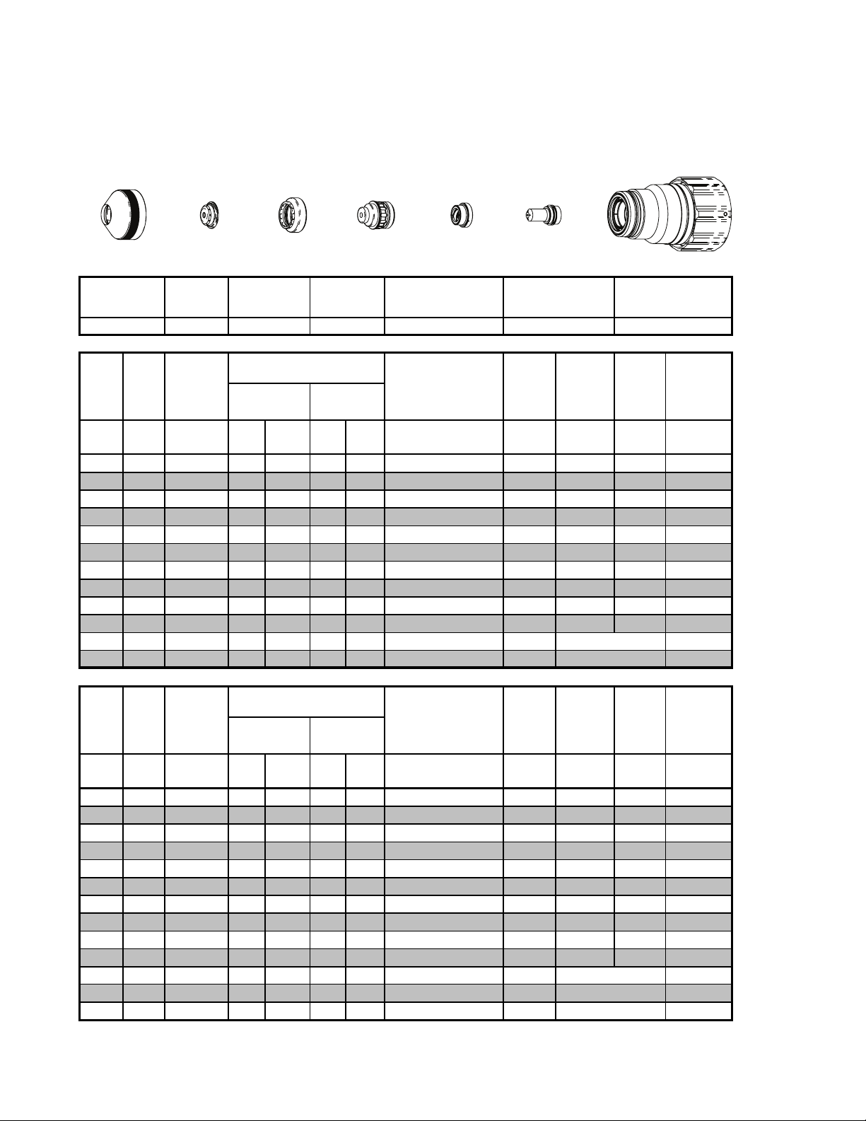
Eff
ti
C
Eff
ti
8.04 Bevel Cutting 150 - 200 Amp
Mild Steel
200A Bevel Cutting
Plasma / Air Shield
O
2
Shield Retainer
Shield
Shield Gas
Distributor
Tip
This Art Is For Reference ONLY
Shield
Retainer
22-1014 22-1285 22-1055 22-1042 22-1093
ve
ec
Cut
Thickness
in in (PSI) (Ball) (PSI) (Ball) (PSI) (ipm) (in) (s ec) (in)
3/16 0.07 15 100 100 NA 100 250 0.300 0.2 0.142
1/4 0.07 15 100 100 NA 100 200 0.300 0.2 0.148
3/8 0.07 15 100 100 NA 100 140 0.350 0.3 0.162
1/2 0.07 15 100 100 NA 100 115 0.350 0.5 0.167
5/8 0.07 15 100 100 NA 100 80 0.350 0.6 0.186
3/4 0.07 15 100 100 NA 100 65 0.400 0.8 0.186
7/8 0.07 15 100 100 NA 100 57 0.400 1.0 0.185
1 0.07 15 100 100 NA 100 48 0.400 1.2 0.193
1 1/4 0.07 15 100 100 NA 100 30 0.425 2.0 0.196
1 1/2 0.07 15 100 100 NA 100 20 0.450 4.0 0.201
2
0.07
2 1/2
0.07
Minimum
Shield
22-1030
Pre Flow
Pressure
(Air)
Clearance
15 100 100
15 100 100
Shield Gas
Distributor
Cu t Fl ow Rate s /
Pressures
Plas ma (O
Tip Electrode
Effective Cut Hieght
) Shield (Air)
2
100 10 0.204
NA
100 8 0.210
NA
Plasma Gas
Distributor
Plasma Gas
Distributor
(in)
.130-.550
.130-.550
.110-.560
.150-.550
.170-.550
.200-.550
.200-.550
.200-.550
.200-.550
.200-.550
.200-.550
.200-.550
Electrode
Travel
Speed
Initial
Piercing
Height
Edge Start
Edge Start
Cartridge
Art # A-07917_AC
Cartridge
Pierce
Delay
22-1022
Kerf Width
@ Rec.
Speed
ve
ec
Cut
Thickness
mm mm (Bar) (Ball) (Bar) (Ball) (Bar)
5
6
8
10
12
15
20
25
32
38
44
50
60 1.80 1.0 100 6.9 NA 6.9 200 5.3
BOLD TYPE
Requires CCM version 3.4 or later. Requires GCM version 3.2 or later
Pre Flow
Pressure
Minimum
1.80
1.80
1.80
1.80
1.80
1.80
1.80
1.80
1.80
1.80
1.80
1.80
(Air)
Clearance
1.0 100 6.9 NA 6.9 6170 7.6 0.2 3.6
1.0 100 6.9 NA 6.9 5360 7.6 0.2 3.7
1.0 100 6.9 NA 6.9 4290 8.3 0.3 3.9
1.0 100 6.9 NA 6.9 3460 8.9 0.3 4.1
1.0 100 6.9 NA 6.9 3060 8.9 0.5 4.2
1.0 100 6.9 NA 6.9 2280 8.9 0.6 4.6
1.0 100 6.9 NA 6.9 1590 10.2 0.9 4.7
1.0 100 6.9 NA 6.9 1250 10.2 1.2 4.9
1.0 100 6.9 NA 6.9 750 10.8 2.1 5.0
1.0 100 6.9 NA 6.9 510 11.4 4.0 5.1
1.0 100 6.9 NA 6.9 390 5.1
1.0 100 6.9 NA 6.9 270 5.2
indicates maximum piercing parameters.
ut Fl ow Ra te s /
Pressures
Plas ma (O
) Shield (Air)
2
Effective Cut Hieght
(mm)
3.3-13.97
3.3-13.97
3.6-13.97
3.9-13.97
4.2-13.97
4.0-13.97
5.1-13.97
5.1-13.97
5.1-13.97
5.1-13.97
5.1-13.97
5.1-13.97
5.1-13.97
BOLD ITA LIC
indicates edge starts only.
Travel
Speed
( mm/ min )
Initial
Piercing
Height
(mm) (sec) (mm)
Edge Start
Edge Start
Edge Start
Pierce
Delay
Kerf Width
@ Rec.
Speed
Manual 0-4829 Rev AN 8-55 TORCH DATA for Ultra-Cut
Page 54

Stainless Steel
Eff
ti
c
ess
Eff
ti
c
ess
C
C
200A Bevel Cut
H35 Plasma / N
Shield Retainer
Shield
Retainer
22-1015 22-1284 22-1095
ve
kn
ec
Material
Thi
in in (PSI) (Ball) (PSI)
3/8 0.07 20 120 100 NA 120 90 0.400 0.4 0.131
1/2 0.07 20 120 100 NA 120 65 0.400 0.5 0.135
5/8 0.07 20 120 100 NA 100 50 0.350 0.6 0.142
3/4 0.07 20 120 100 NA 100 40 0.400 0.8 0.143
7/8 0.07 20 120 100 NA 100 35 0.450 1.0 0.148
1 0.07 20 120 100 NA 120 30 0.450 1.0 0.162
1 1/4
1 1/2
0.07
0.07
2
0.07
Minimum
Clearance
Shield
22-1073
22-1094
Pre Flow
Pressure
(N
20 120 100 NA 120 20 0.170
20 120 100 NA 120 16 0.175
20 120 100 NA 120 12 0.182
Shield
2
Shield Cap
Shield Gas
Distributor
Plasma (H35)
)
2
Shield Gas
Distributor
This Art Is For Reference ONLY
Tip
ut Flow Rates /
Pressures
Shield (N2)
(Ball)
Tip
Plasma Gas
Distributor
Plasma Gas
Distributor
22-1042
Effective Cut Heig ht
(PSI) (ipm ) (in) (sec) (in)
(in)
.300-.450
.300-.451
.300-.452
.300-.453
.300-.454
.300-.455
.300-.456
.300-.457
.300-.458
Electrode
Elec trode Cartridge
22-1096
Travel
Speed
Cartridge Assembly
Initial
Piercing
Height
Edge Start
Edge Start
Edge Start
Art # A-08567
Pierce
Delay
22-1022
Kerf Width
@ Rec.
Speed
ve
kn
ec
Material
Thi
mm mm (Bar) (Ball) (Bar)
10 1.8 1.4 120 6.9 NA 8.3 2200 10.2 0.3 3.4
12 1.8 1.4 120 6.9 NA 8.3 1700 10.2 0.5 3.4
15 1.8 1.4 120 6.9 NA 6.9 1300 8.9 0.6 3.6
20 1.8 1.4 120 6.9 NA 6.9 950 10.2 0.9 3.7
25 1.8 1.4 120 6.9 NA 8.3 770 11.4 1.2 4.0
32 1.8 1.4 120 6.9 NA 8.3 500 4.3
38 1.8 1.4 120 6.9 NA 8.3 400 4.4
44 1.8 1.4 120 6.9 NA 8.3 340 4.5
50 1.8 1.4 120 6.9 NA 8.3 300 4.6
BOLD TYPE
Requires CCM version 3.4 or later. Requires GCM version 3.2 or later
TORCH DATA for Ultra-Cut 8-56 Manual 0-4829 Rev AN
Pre Flow
Pressure
Minimum
(Air)
Clearance
indicates maximum piercing parameters.
ut Flow Rates /
Pressures
Plas m a (O
) Shield (Air)
2
(Bar)
(Ball)
Effective Cut Heig ht
(mm )
7.6-13.97
7.6-13.97
7.6-13.97
7.6-13.97
8.9-13.97
8.9-13.97
8.9-13.97
8.9-13.97
8.9-13.97
BOLD ITALIC
indicates edge starts only.
Travel
Speed
( mm/mi n)
Initial
Piercing
Height
(mm) (sec) (m m )
Edge Start
Edge Start
Edge Start
Edge Start
Pierce
Delay
Kerf Width
@ Rec.
Speed
Page 55

E
i
l
t
c
ess
Stainless Steel
E
i
l
t
c
ess
200A Bevel Cut
Plasma / H2O Shield
N
2
Shield Retainer
Shield
Shield Gas
Distributor
Tip
This Art Is For Reference ONLY
Shield
Retainer
Thi
Clearance
Minimum
kn
in in (PSI) (Ball) (PSI) (Ball) (PSI) (ipm) (in) (s ec) (in)
0.07 3/8 20 80 90 5 55 95 0.300 0.0 0.110
0.07 1/2 20 80 90 5 55 85 0.300 0.4 0.115
0.07 5/8 20 80 90 5 55 65 0.300 0.5 0.122
0.07 3/4 20 80 90 5 55 50 0.300 0.7 0.133
0.07 7/8 20 80 90 5 55 40 0.400 0.9 0.149
0.07 1 20 80 90 5 55 35 0.450 1.0 0.148
0.07 1 1/4 20 80 90 5 55 20 0.176
0.07 1 1/2 20 80 90 5 55 10 0.211
0.07 1 3/4 20 80 90 5 55 8 0.216
Material
qu
va
en
Shield
22-1049
Pre Flow
Pressure
(N
)
2
Shield Gas
Distributor
Cut Flow Ra tes /
Pressures
Plas m a (N
Tip
Shield
)
2
(H
O)*
2
Effective Cut Height
Plasma Gas
Distributor
Plasma Gas
Distributor
22-1043 22-1089 22-102222-1015 22-1284 22-1067
(in)
.160-.550
.160-.550
.180-.550
.200-.550
.250-.550
.300-.550
.300-.550
.350-.450
.350-.450
Electrode
Cartridge
Art # A-08552
Elec trode Cartridge
Travel
Speed
Initial
Piercing
Height
Edge Start
Edge Start
Edge Start
Pierce
Delay
Kerf Width
@ Rec.
Speed
Thi
Clearance
Minimum
Material
qu
kn
mm mm (Bar) (Ball) (Bar) (Ball) (Bar)
1.8 10 1.4 80 6.3 5 3.8 2400 7.6 0.0 2.8
1.8 12 1.4 80 6.3 5 3.8 2000 7.6 0.4 2.9
1.8 15 1.4 80 6.3 5 3.8 1550 7.6 0.5 3.1
1.8 20 1.4 80 6.3 5 3.8 1100 7.6 0.7 3.4
1.8 25
1.8 32 1.4 80 6.3 5 3.8 500 4.5
1.8 38 1.4 80 6.3 5 3.8 250 5.4
1.8 44 1.4 80 6.3 5 3.8 200 5.5
BOLD TYPE
Requires CCM version 3.4 or later. Requires GCM version 3.2 or later.
* Pressure of the water supply line should be regulated by customer pressure regulator.
Ohmic height sensing is not recomm ended with water shield. Water on the plate interferes electrically
Note 1:
with the ohmic sensing circuit.
Water source used for shield must be demineralized.
Note 2:
Manual 0-4829 Rev AN 8-57 TORCH DATA for Ultra-Cut
Pre Flow
va
Pressure
en
indicates maximum piercing parameters.
)
(N
2
1.4 80 6.3 5 3.8 900 11.4 0.9 3.7
Cut Flow Ra tes /
Pressures Travel
Shield
)
2
(H
2
O)*
Effective Cut Height
(mm)
4.1-13.97
4.1-13.97
4.4-19.97
5.1-13.97
7.6-13.97
7.6-13.7
8.9-13.97
8.9-13.97
BOLD ITALIC
indicates edge starts only.
Speed
( mm/mi n)
Initial
Piercing
Height
(mm) (sec) (m m )
Edge Start
Edge Start
Edge Start
Pierce
Delay
Kerf Width
@ Rec.
SpeedPlas m a (N
Page 56

C
Eff
ti
Thickn ess
Eff
ti
Thickness
Aluminum
200A Bevel Cut
H35 Plasma / N
Shield Cap
Shield Retainer
Shield
Retainer
ve
ec
Cutl
in in (PSI) (Ball) (PSI)
3/8 0.07 20 100 100 NA 110 180 0.400 0.4 0.113
1/2 0.07 20 100 100 NA 110 150 0.350 0.2 0.119
5/8 0.07 20 100 100 NA 110 110 0.350 0.3 0.120
3/4 0.07 20 100 100 NA 110 70 0.400 0.4 0.130
7/8 0.07 20 100 100 NA 110 55 0.450 0.5 0.139
1 0.07 20 100 100 NA 110 40 0.500 0.7 0.150
1 1/4 0.07 20 100 100 NA 110 32 0.161
1 1/2 0.07 20 100 100 NA 110 25 0.170
2 0.07 20 100 100 NA 110 15 0.205
Minimum
Shield
22-1073
22-1094
Pre Flow
Pressure
(N
Clearance
)
2
Shield
2
Shield Gas
Distributor
Shield Gas
Distributor
Cut Flow Rates /
Pressures
Plasma (H35)
Cartridge Assembly
Art # A-08567
Initial
Piercing
Height
Edge Start
Edge Start
Edge Start
Tip
Plasma Gas
Distributor
Electrode
This Art Is For Reference ONLY
Tip
Shield (N2)
(PSI) (ipm ) (in) (sec) (in)
(Ball)
Plasma Gas
Distributor
22-1043
Efective Cut Height
(in)
.300-.550
.300-.550
.300-.550
.300-.550
.350-.550
.350-.550
.400-.550
.400-.550
.400-.550
Electrode Cartridge
22-1096
Travel
Speed
Pierce
Delay
22-102222- 1015 22-1284 22-1095
Kerf Width
@ Rec.
Speed
ve
ec
Cut
mm mm (Bar) (Ball) (Bar)
10 1.80 1.4 100 6.9 NA 7.6 4500 10.2 0.4 2.9
12 1.80 1.4 100 6.9 NA 7.6 3850 8.9 0.2 3.0
15 1.80 1.4 100 6.9 NA 7.6 2800 8.9 0.3 3.0
20 1.80 1.4 100 6.9 NA 7.6 1600 10.2 0.5 3.3
25 1.80 1.4 100 6.9 NA 7.6 1050 12.7 0.7 3.8
32 1.80 1.4 100 6.9 NA 7.6 800 4.1
38 1.80 1.4 100 6.9 NA 7.6 640 4.3
44 1.80 1.4 100 6.9
50 1.80 1.4 100 6.9
BOLD TYPE
Requires CCM version 3.4 or later. Requires GCM version 3.2 or later
Pre Flow
Pressure
Minimum
(Air)
Clearance
indicates maximum piercing parameters.
ut Flow Rates /
Pressures
Plas m a (O
)
Shield (Air)
2
(Ball)
NA
NA
Effective Cut Height
(Bar)
7.6 450 4.8
7.6 380 5.2
(mm)
7.6-113.97
7.6-13.97
7.6-13.97
7.6-13.97
8.9-13.97
10.2-13.97
102-13.97
10.2-13.97
10.2-13.97
BOLD ITALIC
Travel
Speed
( mm/mi n)
indicates edge starts only.
Initial
Piercing
Height
(mm ) (sec) (mm)
Edge S t a rt
Edge S t a rt
Edge Start
Edge Start
Pierce
Delay
Kerf Width
@ Rec.
Speed
TORCH DATA for Ultra-Cut 8-58 Manual 0-4829 Rev AN
Page 57

Chart is for Customer Settings
Make Copies as Desired
Shield
Retainer
Mate ri al
Thickn es s
(ga) (in) inch (PSI) (Ball) (PSI)
3/8 0.375
1/2 0.500
5/8 0.625
3/4 0.750
7/8 0.875
11.000
1 1/4 1.250
1 1/2 1.500
22.000
Shield Cap
Pre Flow
Pressure
(N
)
2
Shield Gas
Distributor
Cut Flow Rate s /
Pressures
Plasma (H35)
Tip
Shield (N2)
(PSI) Volts
(Ball)
Plasma Gas
Distributor
Arc
Vol tag e
Working
Torch
Height
(in)
±0.005
Elec trode Cartridge
Travel
Speed
(ipm ) (in) (s ec) (in)
Initial
Piercing
Height
Pierce
Delay
Kerf Width
@ Rec.
Speed
Mate ri al
Thickn es s
(mm)
10
12
15
20
25
32
38
44
50
Pre Flow
Pressure
(N
)
2
(Bar) (Ball) (Bar)
Cut Flow Rate s /
Plas m a
(H35)
Pressures
(Ball)
(Air)
(Bar) Volts
Arc
Vol tag e
Torch
Working
Height
(mm )
±0.1
Travel
Speed
( mm/mi n)
Initial
Piercing
Height
(mm ) (sec) (m m )
Pierce
DelayShield
Kerf Width
@ Rec.
Speed
Manual 0-4829 Rev AN 8-59 TORCH DATA for Ultra-Cut
Page 58

This Page Intentionally Blank
TORCH DATA for Ultra-Cut 8-60 Manual 0-4829 Rev AN
Page 59

Material
Gases
Used
Consumable
Description
200A 150A 100A 70A 50A 30A
Plasma Gas Distributor
22-1042 22-1042 22-1041 22-1041 22-1041
22-1040
O2/O2
O2/O2
O2/Air
Shield Retainer
22-1014
Shield Cup
22-1017 22-1016 22-1016 22-1016 22-1016 22-1016
Cartridge Assy
22-1022 22-1020 22-1020 22-1020 22-1020 22-1020
H35/N2
N2/H2O
Shield Gas Distributor
22-1284 22-1278 22-1274 22-1274 22-1274 22-1274
Air/Air
Shield Retainer
22-1015
Shield Cup
22-1017 22-1016 22-1016 22-1016 22-1016 22-1016
Cartridge Assy
22-1022 22-1020 22-1020 22-1020 22-1020 22-1020
22-1036
22-1035
Air/Air
22-1047
N2/H2O
22-1034
22-1033
Shield Cap
22-1073
H35/N2, SS
22-1073
H35/N2 < 25mm, AL
22-1094
H35/N2 > 25mm, AL
22-1049
N2/H2O
22-1037
H35/N2
22-1048
N2/H2O
22-1062
H35/N2
22-1053
N2/H2O
22-1061
Air/Air
22-1064
N2/H2O
22-1060
22-1059
22-1041
22-1041
22-1041
22-1045
22-1042
H35/N2, SS
22-1043
H35/N2, AL
22-1043
N2/H2O
22-1041
Tip
22-1095
H35/N2
22-1067
N2/H2O
22-1063
H35/N2
22-1092
N2/H2O
22-1093
22-1072
22-1069
22-1068 O2/O2
Electrode
Mild Steel
Electrode
Tip
Stainless
Steel/
Aluminum
Plasma Gas Distributor
22-1055
22-1054
22-1051
22-1152
22-1082
O2/O2
22-1050
O2/O2
22-1171
22-1170
22-1153
Shield Cap
22-1030
22-1027
22-1028
< 20mm
22-1275
> 20mm
22-1077
22-1096
H35/N2
22-1089
N2/H2O
22-1081
22-1079
22-1064
N2/H2O
22-1078
22-1080
H35/N2
22-1089
N2/H2O
22-1026
22-1025
22-1024
O2/O2
Ultra Cut 100/150/200
22-1272
22-1272
Shield Gas Distributor
22-1285
22-1273
22-1272
Manual 0-4829 Rev AN 8-61 TORCH DATA for Ultra-Cut
Art # A-08445
Page 60

This Page Intentionally Blank
TORCH DATA for Ultra-Cut 8-62 Manual 0-4829 Rev AN
Page 61

Insert "250 - 300 Amp
Standard Cutting" Tab.
Discard this sheet.
Manual 0-4829 Rev AN 8-63 TORCH DATA for Ultra-Cut
TAB SHEET
Page 62

TORCH DATA for Ultra-Cut 8-64 Manual 0-4829 Rev AN
Page 63

8.05 Standard Cutting 250 - 300 Amp
Mild Steel
250A
O
Plasma / Air Shield
2
Shield Retainer
Shield
Shield Gas
Distributor
Tip
This Art Is For Reference ONLY
Shield
Retainer
Mate ri al
Thickness
(ga) (in) inch (PSI) (Ball) (PSI) (Ball) (PSI) Volts
5/8 0.625 15 100 100 NA 100 147 0.170 115 0.400 0.6 0.167
3/4 0.750 15 100 100 NA 100 152 0.180 90 0.450 0.8 0.171
7/8 0.875 15 100 100 NA 100 154 0.190 75 0.450 1.0 0.170
1 1.000 15 100 100 NA 90 157 0.200 60 0.500 1.4 0.181
1 1/4 1.250 15 100 100 NA 100 160 0.200 43 0.500 1.8 0.191
1 1/2 1.500 15 100 100 NA 100 164 0.200 33 0.550 3.2 0.197
2 2.000 15 100 100
Shield Cap
Pre Flow
Pressure
(Air)
Shield Gas
Distributor
Cut Flow Rates /
Pressures
2
Tip Electrode Cartridge
) Shield (Air)
NA
100 177 0.200 15 0.197
Plasma Gas
Distributor
Electrode
Plasma Gas
Distributor
22-1042 22-1093
Arc
Vol tag e
Torch
Working
Height
(in)
±0.005
Cartridge
Art # A-07917_AC
22-102222-1014 22-1030 22-1285 22-1056
Travel
Speed
(ipm ) (in) (sec) (in)
Initial
Piercing
Height
Edge Start
Pierce
Delay
Kerf Width
@ Rec.
SpeedPlas m a (O
Mate ri al
Thickness
(mm )
15
20
25
32
38
44 Edge Start
50 Edge Start
25A Arc Current
BOLD TYPE
Requires CCM version 3.6 or later. Requires GCM version 3.2 or later
NOTE:
indicates maximum piercing parameters.
Lock pierce height between 0.5" to 1" to avoid torch hitting the pierce metal puddle.
Pre Flow
Pressure
(Air)
(Bar) (Ball) (Bar) (Ball) (Bar) Volts
1.0 100 6.9 NA 6.9 147 4.2 3060 10.2 0.6 4.2
1.0 100 6.9 NA 6.9 153 4.6 2170 11.4 0.9 4.3
1.0 100 6.9 NA 6.2 157 5.0 1570 12.5 1.3 4.6
1.0 100 6.9 NA 6.9 160 5.1 1080 12.8 1.9 4.9
1.0 100 6.9 NA 6.9 164 5.1 840 14.0 3.2 5.0
1.0 100 6.9
1.0 100 6.9
Pre Flow
Pressure
)
(N
2
(PSI) /
(Bar)
15 60 90 0.120 300 0.120
1.0 4.1 6.2 3.0 7600 3.0
Cut Flow Rates /
Pressures Arc
Plas m a (O
Plas m a (N
(Ball)
80 NA
) Shield (Air)
2
Cut Flow Rates /
Pressures Arc
) Shield (N2)
2
(PSI) /
(Bar)
NA
NA
(Ball)
Torch
Vol tag e
6.9 170 5.1 630 5.0
6.9 176 5.1 410 5.0
Marking
Vol tag e
(PSI) /
(Bar)
BOLD ITALIC
Vol ts
159 0
Working
Height
(mm)
±0.1
Torch
Working
Height
in ±0.005 /
mm ±0. 1
indicates edge starts only.
Allow arc t o extinguis h before height controller retracts at end of cut.
Travel
Speed
( mm/mi n)
Travel
Speed
ipm /
mm/ min
Initial
Piercing
Height
(mm) (sec) (m m)
Initial
Transfer
Height
in ±0.005 /
mm ±0 . 1
Pierce
Delay
Pierce
Delay
(sec)
Kerf Width
@ Rec.
Speed
Mark in g
quality
degrades
thickness
decreases
as
Manual 0-4829 Rev AN 8-65 TORCH DATA for Ultra-Cut
Page 64

Mild Steel
300A
O
Plasma / Air Shield
2
Stainless Steel
300A
H35 Plasma / N
Shield Retainer
Shield
2
Shield Cap
Shield Gas Distributor
(Straight)
(Swirl)
Plasma Gas
Tip
This Art Is For Reference ONLY
Distributor
Electrode
Cartridge Assembly
Art # A-08551_AB
Shield
Retainer
Mate ri al
Thicknes s
(ga) (in) inch psi Ball psi Ball ps i Volts
1/2 0.500 15 104 90 NA 40 147 0.130 150 0.400 0.4 0.190
5/8 0.625 15 104 100 NA 50 152 0.130 115 0.400 0.5 0.190
3/4 0.750 15 104 100 NA 60 154 0.140 100 0.450 0.7 0.190
7/8 0.875 15 104 100 NA 60 155 0.140 85 0.450 0.8 0.190
1 1.000 15 104 100 NA 60 160 0.150 70 0.450 0.9 0.195
1.25 1.250 15 104 100 NA 60 169 0.220 50 0.450 1.0 0.230
1 1/2 1.500 15 104 100 NA 80 176 0.230 35 0.450 1.7 0.245
1 3/4 1.750 15 104 100
2 2.000 15 104 100 NA 90 187 0.230 18 0.280
2 1/2 2.500 15 104 100 NA 90 208 0.230 10 NA
3 3.000 15 104 100 NA 90 219 0.230 7 NA -1283
Mate ri al
Thicknes s
(mm)
30A Arc Current
BOLD TYPE
Requires CCM version 3.4 or later. Requires GCM version 3.2 or later
Shield Cap
Pre Flow
Pres s ure
(Air)
Pre Flow
Pres s ure
(Air
bar Ball bar Ball bar Volts
12
15
20
25
30
35
40
50 Edge Start
60 Edge Start
70
Pre Flow
Pres s ure
(N
(PSI) /
(Bar)
1.0 4.1 6.2 3.0 7600 3.0
indica te s m a xim u m piercing param eters .
Shield Gas
Distribut or
22-1282
22-1283
Cut Flo w Ra tes /
Pres s ures Arc
Plas m a (O
Cut Flo w Ra tes /
Pres s ures Arc
Plas m a (O
)
2
1 104 6.2 NA 2.8 146 3.3 3810 10.2 0.4 4.8
1 104 6.9 NA 3.5 151 3.3 2920 10.2 0.5 4.8
1 104 6.9 NA 4.1 155 3.6 2540 12.7 0.7 4.8
1 104 6.9 NA 4.1 160 3.8 1780 12.7 0.9 5.0
1 104 6.9 NA 4.1 168 5.6 1270 12.7 1.0 5.8
1 104 6.9 NA 5.5 175 5.8 900 12.7 1.7 6.2
1 104 6.9
1 104 6.9
1 104 6.9
1 104 6.9
Cut Flo w Ra tes /
Pres s ures Arc
Plas m a (N
)
2
(PSI) /
(Ball)
(Bar)
15 60 90 0.120 300 0.120
80 NA
Tip
22-1057
) Shield (Air)
2
NA
90 182 0.230 25 0.450 3.000 0.275
) Shield (Air)
2
NA
6.2 180 5.8 660 12.7 3.0 6.6
NA
6.2 187 5.8 460 7.1
NA
6.2 201 7.6 325 NA
NA
6.2 212 7.6 285 NA -1283
) Shield (N2)
2
(PSI) /
(Ball)
(Bar)
BOLD ITALIC
Plasma Gas
Distribut or
22-1042 22-1090 22-102222-1021 22-1029
Torch
Vol tag e
Vol tag e
Marking
Vol tag e
Vo lt s
Working
Height
(in)
±0.005
Torch
Working
Height
(mm)
±0.1
Torch
Working
Height
in ±0.005 /
mm ±0 . 1
158 0
indicates edge starts only.
Electrode Cartridge
Travel
Speed
(ipm) (in) (sec) (in)
Travel
Speed
( mm/mi n )
Travel
Speed
ipm /
mm/ min
Initial
Piercing
Height
Edge Start
Edge Start
Edge Start
Initial
Piercing
Height
(mm ) (sec) (mm)
Edge Start
Initial
Transfer
Height
in ±0.005 /
mm ±0.1
Pierce
Delay
Pierce
Delay
Pierce
Delay
(sec)
Kerf Width
@ Rec.
Kerf Width
@ Rec.
Speed
Speed
degrades
thickn es s
decreases
Shield
Gas
Distributor
-1282
-1282
-1282
-1282
-1282
-1283
-1283
-1283
-1283
-1283
Shield
Gas
Distributor
-1282
-1282
-1282
-1282
-1283
-1283
-1283
-1283
-1283
Ma rki ng
quality
as
TORCH DATA for Ultra-Cut 8-66 Manual 0-4829 Rev AN
Page 65

Stainless Steel
300A
H35 Plasma / N
Shield Retainer
Shield
Retainer
Mate ri al
Thickness
(ga) (in) inch ps i Ball psi Ball ps i Volts
Shield Cap
< 1" / 25mm 22-1038,
1" / 25mm + 22-1039
Shield
2
Shield Cap
Pre Flow
Pressure
(N
)
2
Shield Gas
Distributor
Tip
This Art Is For Reference ONLY
Shield Gas
Dist ributor
22-1284 22-1065
Cut Flow Rate s /
Pressures Arc
(H35)
Tip
Shield (N
Plasma Gas
Distributor
VoltagePlas m a
)
2
Plasma Gas
Dist ributor
22-1041 22-1091 22-102222-1015
Torch
Working
Height
(in)
±0.005
Cartridge Assembly
Electrode
Art # A-08567
Elec trode Cartridge
Travel
Speed
Initial
Piercing
Height
(ipm ) (in) (s ec) (in)
Pierce
Delay
Kerf Width
@ Rec.
Speed
3/8 0.375 20 120 100 NA 120 160 0.350 85 0.350 0.2 0.175
1/2 0.500 20 120 100 NA 120 168 0.350 75 0.350 0.4 0.193
5/8 0.625 20 120 100 NA 90 163 0.350 65 0.375 0.5 0.197
3/4 0.750 20 120 100 NA 90 168 0.350 55 0.375 0.6 0.195
7/8 0.875 20 120 100 NA 90 170 0.350 45 0.375 0.7 0.210
1 1.000 20 120 100 NA 120 173 0.350 35 0.500 0.9 0.226
1 1/4 1.250 20 120 100 NA 120 180 0.400 30 0.500 1.0 0.203
1 1/2 1.500 20 120 100
2 2.000 20 120 100
NA
120 180 0.400 25 0.220
NA
120 186 0.400 17 0.237
Edge Start
Edge Start
Mate ri al
Thickness
(mm)
10
12
15
20
25
32
38 Edge Start
44 Edge Start
50 Edge Start
24A Arc Current
BOLD TYPE
indicates maximum piercing parameters.
Pre Flow
Pressure
(N2)
bar Ball bar Ball bar Volts
Cut Flow Rate s /
Pressures Arc
Plas m a
(H35)
Shield (N
)
2
Voltage
Torch
Working
Height
(mm)
±0.1
Travel
Speed
( mm/mi n)
Initial
Piercing
Height
Pierce
Delay
(mm) (sec) (mm)
1.4 120 6.9 NA 8.3 161 8.9 2120 8.9 0.2 4.5
1.4 120 6.9 NA 8.3 166 8.9 1960 8.9 0.4 4.8
1.4 120 6.9 NA 6.2 164 8.9 1720 9.4 0.5 5.0
1.4 120 6.9 NA 6.2 169 8.9 1320 9.5 0.6 5.1
1.4 120 6.9 NA 8.3 173 8.9 920 12.3 0.9 5.7
1.4 120 6.9 NA 8.3 180 10.2 760 12.3 1.0 5.2
1.4 120 6.9 NA 8.3 180 10.2 640 5.6
1.4 120 6.9 NA 8.3 183 10.2 540 5.8
1.4 120 6.9 NA 8.3 186 10.2 450 6.0
Marking
Pre Flow
Pressure
(N
)
2
(PSI) /
(Bar)
15 60 90 0.120 300 0.120
1.0 4.1 6.2 3.0 7600 3.0
Cut Flow Rate s /
Pressures Arc
Plas m a (N
(Ball)
) Shield (N2)
2
(PSI) /
(Bar)
(Ball)
(PSI) /
(Bar)
Voltage
Vol ts
Torch
Working
Height
in ±0.005 /
mm ±0. 1
Travel
Speed
ipm /
mm/ min
Initial
Transfer
Height
in ±0.005 /
mm ±0.1
80 NA 135 0
BOLD ITALIC
indicates edge starts only.
Pierce
Delay
(sec)
Kerf Width
@ Rec.
Speed
Mark in g
quality
degrades
as
thickness
decreases
Manual 0-4829 Rev AN 8-67 TORCH DATA for Ultra-Cut
Page 66

Stainless Steel
300A
N
Plasma / H2O Shield
2
Shield Retainer
Shield
Shield Gas
Distributor
Tip
Plasma Gas
Distributor
Electrode
Cartridge
Initial
Height
Edge Start
Edge Start
Edge Start
Initial
Height
Edge Start
Initial
Height
mm ±0.1
Art # A-07917_AC
Pierce
Delay
Pierce
Delay
Pierce
Delay
(sec)
Kerf Width
Kerf Width
degrades
thicknes s
decreases
This Art Is For Reference ONLY
Shield
Retainer
Mate ri al
Thicknes s
(ga) (in) inch psi Ball psi Ball psi Volts
3/8 0.375 20 120 100 8 55 150 0.150 140 0.350 0.3 0.144
1/2 0.500 20 120 100 8 55 159 0.150 100 0.350 0.5 0.154
5/8 0.625 20 120 100 8 55 158 0.150 75 0.350 0.1 0.153
3/4 0.750 20 120 100 8 55 166 0.200 55 0.500 0.7 0.173
7/8 0.875 20 120 100 8 55 180 0.300 45 0.500 1.1 0.210
1 1.000 20 120 100 8 55 182 0.300 40 0.500 1.3 0.210
1 1/4 1.250 20 120 100 8 55 196 0.350 30 0.500 2.0 0.230
1 1/2 1.500 20 120 100
1 3/4 1.750 20 120 100
2 2.000 20 120 100
Mate ri al
Thicknes s
(mm)
24 A Arc Curre nt
Burn-through
may occur
for th ickn es s e s
< 1/16" (0.063") / 1.6
mm.
BOLD TYPE
* Pressure of the water supply line should be regulated by customer pressure regulator.
Ohmic height sens ing is not recomm ended with water shield. Water on the plate interferes electrically with the
Note1:
ohmic sens ing circuit.
Water source used for shield must be dem ineralized.
Note2:
Shield Cap
Pre Flow
Pres s ure
(N
Pre Flow
Pres s ure
(N
bar Ball bar Ball bar Volts
10
12
15
20
25
32
38 Edge Start
44 Edge Start
50
indicates maximum piercing parameters.
1.4 120 6.9 8 3.8 151 3.8 3400 8.9 0.3 3.7
1.4 120 6.9 8 3.8 157 3.8 2760 8.9 0.5 3.9
1.4 120 6.9 8 3.8 158 3.8 2080 9.4 0.6 3.9
1.4 120 6.9 8 3.8 170 5.8 1320 12.7 0.8 4.7
1.4 120 6.9 8 3.8 182 7.6 1030 12.7 1.3 5.3
1.4 120 6.9 8 3.8 196 8.9 760 12.7 2.0 5.8
1.4 120 6.9 8 3.8 198 8.9 640 5.9
1.4 120 6.9
1.4 120 6.9
Pre Flow
Pres s ure
(N
(PSI) /
(Bar)
1.0 4.1 6.2 3.0 7600 3.0
Shield Gas
Distributor
Cu t Flow Ra tes /
Press ures Arc
Plas m a (N
)
2
Cu t Flow Ra tes /
Press ures
Plas m a (N
)
2
Cu t Flow Ra tes /
Press ures Arc
Plas m a (N
)
2
(PSI) /
(Ball)
(Bar)
15 60 90 0.120 300 0.120
80 NA
Tip
Shield
)
2
(H
O)*
2
8
55 198 0.350 25 0.232
8
55 198 0.350 18 0.237
8
55 205 0.350 12 0.253
Shield
)
2
(H
O)*
2
8
3.8 198 8.9 470 6.0
8
3.8 204 8.9 320 6.4
) Shield (N2)
2
(PSI) /
(Ball)
(Bar)
BOLD ITALIC
Plasma Gas
Distributor
22-1043 22-1089 22-102222-1015 22-1046 22-1284 22-1066
Torch
Vol tag e
Vol tag e
Marking
Vol tag e
Vo lt s
Working
Height
(in)
±0.005
Arc
115 0
Torch
Working
Height
(mm)
±0.1
Torch
Working
Height
in ±0.005 /
mm ± 0 . 1
indicates edge s tarts only.
Electrode Cartridge
Travel
Speed
(ipm) (in) (sec) (in)
Travel
Speed
( mm/mi n) (mm) (sec) (mm)
Travel
Speed
ipm /
mm/ min
Piercing
Piercing
Transfer
in ±0.005 /
@ Rec.
Speed
@ Rec.
Speed
Markin g
quality
as
TORCH DATA for Ultra-Cut 8-68 Manual 0-4829 Rev AN
Page 67

Aluminium
300A
H35 Plasma / N
Shield Retainer
Shield
Retainer
Mate ri al
Thickness
(ga) (in) inch psi Ball psi Ball psi Volts
1/4 0.250 20 120 100 NA 120 163 0.400 300 0.400 0.1 0.182
3/8 0.375 20 120 100 NA 120 163 0.400 275 0.400 0.2 0.186
1/2 0.500 20 120 100 NA 120 153 0.300 210 0.400 0.3 0.174
5/8 0.625 20 120 100 NA 90 160 0.300 140 0.350 0.4 0.169
3/4 0.750 20 120 100 NA 90 159 0.300 110 0.350 0.5 0.172
7/8 0.875 20 120 100 NA 90 162 0.300 95 0.400 0.6 0.183
1 1.000 20 120 100 NA 120 165 0.350 85 0.450 0.7 0.190
1 1/4 1.250 20 120 100 NA 120 168 0.400 60 0.205
1 1/2 1.500 20 120 100 NA 120 177 0.400 45 0.215
1 3/4 1.750 20 120 100 NA 120 182 0.400 35 0.226
2 2.000 20 120 100 NA 120 188 0.400 25 0.215
Shield Cap
< 1" / 25mm 22-1038,
1" / 25mm + 22-1039
Shield
2
Shield Cap
Pre Flow
Pres s ure
)
(N
2
Shield Gas
Distributor
This Art Is For Reference ONLY
Shield Gas
Dis tribut or
22-1284 22-1065
Cut Flow Rates /
Pres s ures Arc
Plas m a
(H35)
Shield (N
Tip
Tip
)
2
Voltage
Plasma Gas
Distributor
Plasma Gas
Dis tribut or
22-1041 22-1091 22-102222-1015
Torch
Working
Height
(in)
±0.005
Cartridge Assembly
Electrode
Art # A-08567
Elec trode Cartridge
Travel
Speed
(ipm ) (in) (s ec) (in)
Initial
Piercing
Height
Edge Star t
Edge Star t
Edge Star t
Edge Star t
Pierce
Delay
Kerf Width
@ Rec.
Speed
Mate ri al
Thickness
(mm )
6
8
10
12
15
20
25
32 Edge Star t
38 Edge Star t
44 Edge Star t
50 Edge Star t
24 A Arc Cur r e nt
Burn-through
may occur
for thicknesses
< 1/16" (0.063") / 1.6
mm.
BOLD TYPE
indicates maximum piercing parameters.
Pre Flow
Pres s ure
)
(N
2
bar Ball bar Ball bar Volts
1.4
1.4 120 6.9 NA 8.3 163 10.2 7290 10.2 0.2 4.7
1.4 120 6.9 NA 8.3 162 9.8 6740 10.2 0.2 4.7
1.4 120 6.9 NA 8.3 155 8.2 5700 10.2 0.3 4.5
1.4 120 6.9 NA 6.2 158 7.6 4050 9.2 0.4 4.3
1.4 120 6.9 NA 6.2 160 7.6 2680 9.3 0.5 4.5
1.4 120 6.9 NA 8.3 165 8.7 2190 11.3 0.7 4.8
1.4 120 6.9 NA 8.3 168 10.2 1510 5.2
1.4 120 6.9 NA 8.3 177 10.2 1150 5.5
1.4 120 6.9 NA 8.3 182 10.2 910 5.7
1.4 120 6.9 NA 8.3 185 10.2 670 5.8
Pre Flow
Pres s ure
(N
)
2
(PSI) /
(Bar)
15 60 90 0.120 300 0.120
1.0 4.1 6.2 3.0 7600 3.0
Cut Flow Rates /
Pressures
Plas m a
(H35)
120 6.9 NA 8.3 163 10.2 7620 10.2 0.1 4.7
Cut Flow Rates /
Plas m a (N
(Ball)
80 NA 135 0
Shield (N
Pres s ures Arc
) Shield (N2)
2
(PSI) /
(Bar)
(Ball)
(PSI) /
(Bar)
Arc
Voltage
)
2
Marking
Voltage
Vo lts
BOLD ITALIC
Torch
Working
Height
(mm)
±0.1
Torch
Working
Height
in ±0.005 /
mm ±0.1
indicates edge s tarts only.
Travel
Speed
( mm/mi n)
Travel
Speed
ipm /
mm/ min
Initial
Piercing
Height
(mm) (sec) (mm)
Initial
Transfer
Height
in ±0.005 /
mm ±0.1
Pierce
Delay
Pierce
Delay
(sec)
Kerf Width
@ Rec.
Speed
Ma rk in g
quality
degrades
as
thickness
decreases
Manual 0-4829 Rev AN 8-69 TORCH DATA for Ultra-Cut
Page 68
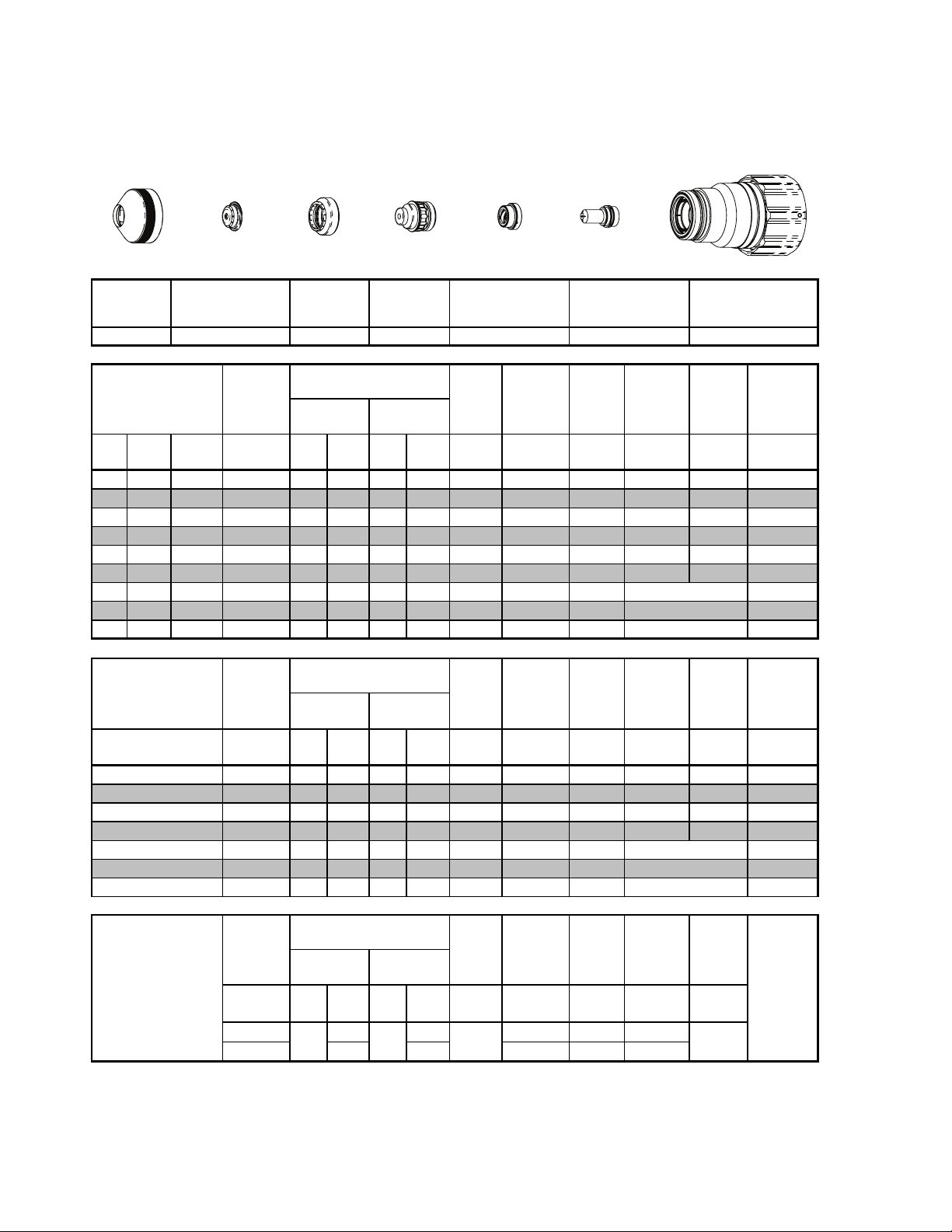
Aluminium
300A
N
Plasma / H2O Shield
2
Shield Retainer
Shield
Distributor
Tip
This Art Is For Reference ONLY
Shield Gas
Shield
Retainer
Ma teri al
Thi cknes s
(ga) (in) inch ps i Ball psi Ball psi Volts
1/2 0.500 20 120 100 8 55 160 0.200 120 0.300 0.3 0.161
5/8 0.625 20 120 100 8 55 164 0.200 100 0.300 0.4 0.165
3/4 0.750 20 120 100 8 55 170 0.250 80 0.500 0.5 0.174
7/8 0.875 20 120 100 8 55 173 0.250 70 0.500 0.6 0.175
1 1.000 20 120 100 8 55 175 0.250 60 0.500 0.7 0.190
1 1/4 1.250 20 120 100 8 55 180 0.250 40 0.500 1.2 0.185
1 1/2 1.500 20 120 100 8 55 184 0.300 25 0.190
1 3/4 1.750 20 120 100
2 2.000 20 120 100
Shield Cap
Pre Flow
Pres s ure
(N
)
2
Shield Gas
Distributor
Cut Flow Rates /
Pres s ures Arc
Plas ma (N
)
2
8
8
Tip
Shield
O)*
(H
2
55 196 0.300 15 0.213
55 200 0.300 10 0.205
Plasma Gas
Distributor
Plasma Gas
Distributor
22-1043 22-1089 22-102222-1015 22-1046 22-1284 22-1066
Voltage
Torch
Working
Height
(in)
±0.005
Electrode
Cartridge
Art # A-07917_AC
Elect rode Cartridge
Travel
Speed
(ipm ) (in) (sec) (in)
Initial
Piercing
Height
Pierce
Delay
Edge Start
Edge Start
Edge Start
Kerf Width
@ Rec.
Speed
Ma teri al
Thi cknes s
(mm)
15
20
25
32
38 Edge Start
44 Edge Start
50 Edge Start
24A Arc Current
BOLD TYPE
* Pressure of the water supply line s hould be regulated by customer pressure regulator.
Note1:
ohmic sensing circuit.
Note2:
indicates maximum piercing parameters.
Ohmic height sensing is not recommended with water shield. Water on the plate interferes electrically with the
Water source used for shield must be demineralized.
Pre Flow
Pres s ure
)
(N
2
bar Ball bar Ball bar Volts
1.4 120 6.9 8 3.8 163 5.1 2680 7.6 0.4 4.2
1.4 120 6.9 8 3.8 171 6.4 1960 12.7 0.5 4.4
1.4 120 6.9 8 3.8 175 6.4 1560 12.2 0.7 4.8
1.4 120 6.9 8 3.8 180 6.4 1000 0.2 1.2 4.7
1.4 120 6.9 8 3.8 184 7.6 640 4.8
1.4 120 6.9 8 3.8 195 7.6 400 5.4
1.4 120 6.9 8 3.8 199 7.6 270 5.2
Pre Flow
Pres s ure
(N
)
2
(PSI) /
(Bar)
15 60 90 0.120 300 0.120
1.0 4.1 6.2 3.0 7600 3.0
Cut Flow Rates /
Pres s ures Arc
)
2
Cut Flow Rates /
Pres s ures Arc
Plas ma (N
(Ball)
80 NA
) Shield (N2)
2
(PSI) /
(Bar)
(Ball)
Shield
O)*
(H
2
Marking
(PSI) /
(Bar)
BOLD ITALIC
Torch
Voltage
Voltage
Vo lts
Working
Height
(mm)
±0.1
Torch
Working
Height
in ±0.005 /
mm ±0 . 1
115 0
indicates edge starts only.
Travel
Speed
(mm/min)
Travel
Speed
ipm /
mm/ min
Initial
Piercing
Height
(mm) (sec) (mm )
Initial
Transfer
Height
in ±0.005 /
mm ±0. 1
Pierce
Delay
Pierce
Delay
(sec)
Kerf Width
@ Rec.
SpeedPlas ma (N
Mark in g
quality
degrades
as
thicknes s
decreases
TORCH DATA for Ultra-Cut 8-70 Manual 0-4829 Rev AN
Page 69

Insert "250 - 300 Amp
Bevel Cutting" Tab.
Discard this sheet.
Manual 0-4829 Rev AN 8-71 TORCH DATA for Ultra-Cut
TAB SHEET
Page 70

TORCH DATA for Ultra-Cut 8-72 Manual 0-4829 Rev AN
Page 71

Eff
ti
t
c
ess
Eff
ti
c
ess
8.06 Bevel Cutting 250 - 300 Amp
Mild Steel
300A Bevel Cut
O
Plasma / Air Shield
2
Shield Gas Distributor
Shield Retainer
Shield Cap
(Straight)
(Swirl)
Tip
This Art Is For Reference ONLY
Plasma Gas
Distributor
Cartridge Assembly
Electrode
Art # A-08551_AB
Shield
Retainer
22-1021
ve
kn
ec
Material
Thi
in in psi Ball ps i Ball ps i (ipm) (in) (sec) (in)
1/2 0.08 15 104 90 NA 40 150 0.400 0.4 0.190
5/8 0.08 15 104 100 NA 50 115 0.400 0.5 0.190
3/4 0.08 15 104 100 NA 60 100 0.450 0.7 0.190
7/8 0.08 15 104 100 NA 60 85 0.450 0.8 0.190
1 0.08 15 104 100 NA 60 70 0.450 0.9 0.195
1.25 0.08 15 104 100 NA 60 50 0.450 1.0 0.230
1 1/2 0.08 15 104 100 NA 80 35 0.450 1.7 0.245
1 3/4 0.08 15 104 100 NA 90 25 0.450 3.000 0.275
2 0 .08 15 104 100 NA 90 18 0.280
2 1/2 0.08 15 104 100 NA 90 10 NA
3 0.08 15 104 100 NA 90 7 NA -1283
ve
kn
ec
Material
Thi
mm mm bar Ball bar Ball bar
12 2.00 1 104 6.2 NA 2.8 3810 10.2 0.4 4.8
15 2.00 1 104 6.9 NA 3.5 2920 10.2 0.5 4.8
20 2.00 1 104 6.9 NA 4.1 2540 12.7 0.7 4.8
25 2.00 1 104 6.9 NA 4.1 1780 12.7 0.9 5.0
30 2.00 1 104 6.9 NA 4.1 1270 12.7 1.0 5.8
35 2.00 1 104 6.9 NA 5.5 900 12.7 1.7 6.2
40 2.00 1 104 6.9 NA 6.2 660 12.7 3.0 6.6
50 2.00 1 104 6.9 NA 6.2 460 7.1
60 2.00 1 104 6.9 NA 6.2 325 NA
70 2.00 1 104 6.9 NA 6.2 285 NA -1283
BOLD TYPE
Shield
22-1029
Pre Flow
Pressure
Minimum
Minimum
(Air)
Clearance
Pre Flow
Pressure
(Air
Clearance
indicates maximum piercing parameters.
)
2
Shield Gas
Distributor
22-1282
22-1283
Cut Flow Rate s /
Pressures
Plas m a (O
Cut Flow Rate s /
Pressures Travel
Plas m a (O
)
2
)
2
Tip
22-1057
Shield
(Air)
Shield
(Air)
Plasma Gas
Distributor
22-1042 22-1090 22-1022
Effective Cut Height
(in)
.130-.550
.130-.550
.140-.550
.140-.550
.150-.550
.220-.550
.230-.550
.230-.550
.230-.550
.230-.550
.230-.550
Effective Cut Height
(mm)
3.3-13.97
3.3-13.97
3.6-13.97
3.8-13.97
5.6-13.97
5.8-13.97
5.8-13.97
5.8-13.97
7.6-13.97
7.6-13.97
BOLD ITALIC
Electrode
Travel
Speed
Speed
(mm/min)
indicates edge starts only.
Initial
Piercing
Height
Edge Start
Edge Start
Edge Start
Initial
Piercing
Height
(mm) (sec) (mm)
Edge Start
Edge Start
Edge Start
Pierce
Delay
Pierce
Delay
Cartridge
Kerf Width
@ Rec.
Speed
Kerf Width
@ Rec.
Speed
Shield
Gas
Distributor
-1282
-1282
-1282
-1282
-1282
-1283
-1283
-1283
-1283
-1283
Shield
Gas
Distributor
-1282
-1282
-1282
-1282
-1283
-1283
-1283
-1283
-1283
Requires CCM version 3.4 or later. Requires GCM version 3.2 or later.
Manual 0-4829 Rev AN 8-73 TORCH DATA for Ultra-Cut
Page 72

Equivalent
Thickn ess
Stainless Steel
Equivalent
Thickn ess
300A Bevel Cut
H35 Plasma / N
Shield Retainer
Shield
Retainer
Material
in in psi Ball psi Ball psi (ipm) (in) (sec) (in)
3/8 0.08 20 120 100 NA 120 85 0.350 0.2 0.175
1/2 0.08 20 120 100 NA 120 75 0.350 0.4 0.193
5/8 0.08 20 120 100 NA 90 65 0.375 0.5 0.197
3/4 0.08 20 120 100 NA 90 55 0.375 0.6 0.195
7/8 0.08 20 120 100 NA 90 45 0.375 0.7 0.210
1 0.08 20 120 100 NA 120 35 0.500 0.9 0.226
1 1/4 0.08 20 120 100 NA 120 30 0.500 1.0 0.203
1 1/2 0.08 20 120 100 NA 120 25 0.220
2 0.08 20 120 100 NA 120 17 0.237
Minimum
Shield
22-1038
22-1039
Pre Flow
Pressure
(N
Clearance
Shield
2
Shield Cap
Shield Gas
Distributor
)
2
Shield Gas
Distributor
Cut Flow Rates /
Pres sures
Plasm a
(H35)
Shield (N2)
Tip
Plasma Gas
Distributor
This Art Is For Reference ONLY
Tip
Plasma Gas
Distributor
22-1041 22-1091 22-102222-1015 22-1284 22-1065
Effective Cut
Height
(in)
.350-.550
.350-.550
.350-.550
.350-.550
.350-.550
.350-.550
.400-.550
.400-.550
.400-.550
Cartridge Assembly
Electrode
Art # A-08567
Electrode Cartridge
Travel
Speed
Initial
Piercing
Height
Edge Start
Edge Start
Pierce
Delay
Kerf Width
@ Rec.
Speed
Pre Flow
Pressure
(N
Material
Minimum
Clearance
mm mm bar Ball bar Ball bar
10 2.00
12 2.00
15 2.00
20 2.00
25 2.00
32 2.00
38 2.00
44 2.00
50 2.00 1.4 120 6.9 NA 8.3 450 6.0
BOLD TYPE
indicates m aximum piercing parameters.
)
2
1.4 120 6.9 NA 8.3 2120 8.9 0.2 4.5
1.4 120 6.9 NA 8.3 1960 8.9 0.4 4.8
1.4 120 6.9 NA 6.2 1720 9.4 0.5 5.0
1.4 120 6.9 NA 6.2 1320 9.5 0.6 5.1
1.4 120 6.9 NA 8.3 920 12.3 0.9 5.7
1.4 120 6.9 NA 8.3 760 12.3 1.0 5.2
1.4 120 6.9 NA 8.3 640 5.6
1.4 120 6.9 NA 8.3 540 5.8
Cut Flow Rates /
Pressures Travel
Plasm a
(H35)
Shield (N
Effective Cut
)
2
BOLD ITALIC
Height
(mm )
8.9-13.97
8.9-13.97
8.9-13.97
8.9-13.97
8.9-13.97
10.2-13.97
10.2-13.97
10.2-13.97
10.2-13.97
Initial
Speed
( mm/mi n)
indicates edge starts only.
Piercing
Height
(mm) (s ec) (mm )
Edge Start
Edge Start
Edge Start
Pierce
Delay
Kerf Width
@ Rec.
Speed
TORCH DATA for Ultra-Cut 8-74 Manual 0-4829 Rev AN
Page 73
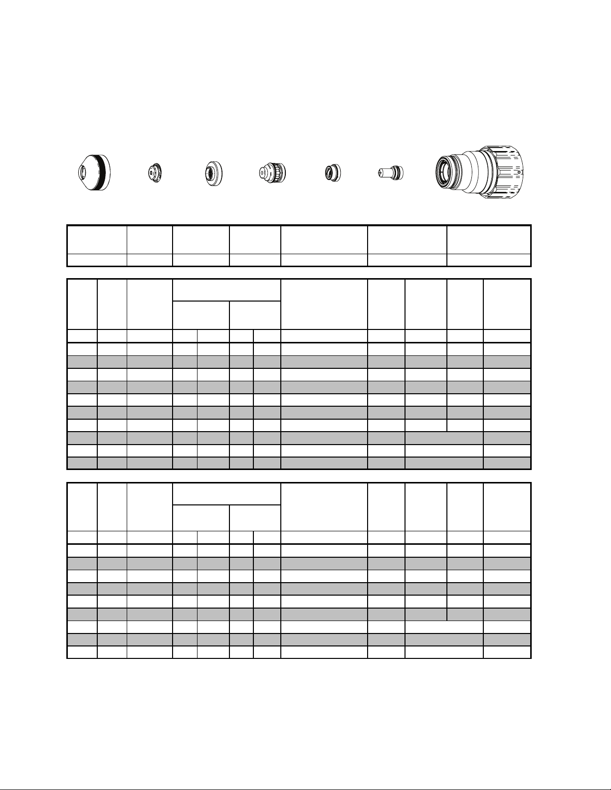
Eff
ti
Thickness
Stainless Steel
Eff
ti
Thickn ess
300A Bevel Cut
N
Plasma / H2O Shield
2
Shield Retainer
Shield
Shield Gas
Distributor
Tip
This Art Is For Reference ONLY
Shield
Retainer
ve
ec
Material
in in psi Ball psi Ball psi (ipm) (in) (sec) (in)
3/8 0.08 20 120 100 8 55 140 0.350 0.3 0.144
1/2 0.08 20 120 100 8 55 100 0.350 0.5 0.154
5/8 0.08 20 120 100 8 55 75 0.350 0.1 0.153
3/4 0.08 20 120 100 8 55 55 0.500 0.7 0.173
7/8 0.08 20 120 100 8 55 45 0.500 1.1 0.210
1 0.08 20 120 100 8 55 40 0.500 1.3 0.210
1 1/4 0.08 20 120 100 8 55 30 0.500 2.0 0.230
1 1/2 0.08 20 120 100 8 55 25 0.232
1 3/4 0.08 20 120 100 8 55 18 0.237
2 0.08 20 120 100 8 55 12 0.253
Minimum
Shield
22-1046
Pre Flow
Pressure
(N
Clearance
)
2
Shield Gas
Distributor
Cut Flow Rates /
Pressures
Plas m a (N
2
)
Tip
Shield
O)*
(H
2
Plasma Gas
Distributor
Plasma Gas
Distributor
22-1043
Effective Cut Height
(in)
.150-.550
.150-.550
.150-.550
.200-.550
.300-.550
.300-.550
.350-.550
.350-.550
.350-.550
.350-.550
Electrode
Cartridge
Art # A-08552
Electrode Cartridge
22-1089 22-102222-1015 22-1284 22-1066
Travel
Speed
Initial
Piercing
Height
Edge Start
Edge Start
Edge Start
Pierce
Delay
Kerf Width
@ Rec.
Speed
ve
ec
Material
mm mm bar Ball bar Ball bar
10 2.00 1.4 120 6.9 8 3.8 3400 8.9 0.3 3.7
12 2.00 1.4 120 6.9 8 3.8 2760 8.9 0.5 3.9
15 2.00 1.4 120 6.9 8 3.8 2080 9.4 0.6 3.9
20 2.00 1.4 120 6.9 8 3.8 1320 12.7 0.8 4.7
25 2.00 1.4 120 6.9 8 3.8 1030 12.7 1.3 5.3
32 2.00 1.4 120 6.9 8 3.8 760 12.7 2.0 5.8
38 2.00 1.4 120 6.9 8 3.8 640 5.9
44 2.00 1.4 120 6.9 8 3.8 470 6.0
50 2.00 1.4 120 6.9 8 3.8 320 6.4
BOLD TYPE
* Pressure of the water supply line should be regulated by customer pressure regulator.
Ohmic height sensing is not recomm ended with water shield. Water on the plate interferes electrically
Note1:
with the ohmic sensing circuit.
Water source used for shield mus t be demineralized.
Note2:
Pre Flow
Pressure
)
(N
Minimum
Clearance
indicates maximum piercing parameters.
2
Cut Flow Rates /
Pressures
Plas m a (N
2
)
Shield
O)*
(H
2
Efee ctive Cut Height
(mm)
3.8-13.97
3.8-13.97
3.8-13.97
5.8-13.97
7.6-13.97
8.9-13.97
8.9-13.97
8.9-13.97
8.9-13.97
BOLD ITALIC
indicates edge starts only.
Travel
Speed
( mm/mi n)
Initial
Piercing
Height
(mm) (sec) (m m )
Edge Start
Edge Start
Edge Start
Pierce
Delay
Kerf Width
@ Rec.
Speed
Manual 0-4829 Rev AN 8-75 TORCH DATA for Ultra-Cut
Page 74

Aluminium
E
i
l
t
Thi ckness
E
i
l
t
Thickness
300A Bevel Cut
H35 Plasma / N
Shield Cap
Shield Retainer
Shield
Retainer
en
va
qu
Material
in in psi Ball psi Ball psi (ipm) (in) (sec) (in)
1/4 0.08 20 120 100 NA 120 300 0.400 0.1 0.182
3/8 0.08 20 120 100 NA 120 275 0.400 0.2 0.186
1/2 0.08 20 120 100 NA 120 210 0.400 0.3 0.174
5/8 0.08 20 120 100 NA 90 140 0.350 0.4 0.169
3/4 0.08 20 120 100 NA 90 110 0.350 0.5 0.172
7/8 0.08 20 120 100 NA 90 95 0.400 0.6 0.183
1 0.08 20 120 100 NA 120 85 0.450 0.7 0.190
1 1/4
1 1/2
1 3/4
0.08
0.08
0.08
2
0.08
Minimum
Shield
22-1038
22-1039
Pre Flow
Pressure
(N
Clearance
20 120 100 NA 120 60 0.205
20 120 100 NA 120 45 0.215
20 120 100 NA 120 35 0.226
20 120 100 NA 120 25 0.215
)
2
Shield
2
Shield Gas
Distributor
Shield Gas
Distributor
Cut Flow Rates /
Pressures
Plas m a
(H35)
Tip
Plasma Gas
Distributor
This Art Is For Reference ONLY
)
2
Plasma Gas
Distributor
22-1041
Effective Cut
Height
(in)
.400-.450
.400-.450
.400-.450
.300-.450
.300-.450
.300-.450
.350-.450
.400-.450
.400-.450
.400-.450
.400-.450
Tip
Shield (N
Cartridge Assembly
Electrode
Art # A-08567
Electrode Cartridge
Travel
Speed
Initial
Piercing
Height
Edge Start
Edge Start
Edge Start
Edge Start
Pierce
Delay
22-102222-1015 22-1284 22- 1065 22-1091
Kerf Width
@ Rec.
Speed
en
va
qu
Material
mm mm bar Ball bar Ball bar
6 1.80 1.4
81.80
10 1.80
12 1.80
15 1.80
20 1.80
25 1.80
32
38
44
50
BOLD TYPE
TORCH DATA for Ultra-Cut 8-76 Manual 0-4829 Rev AN
Pre Flow
Pressure
Minimum
1.80
1.80
1.80
1.80
(N2)
Clearance
1.4 120 6.9 NA 8.3 7290 10.2 0.2 4.7
1.4 120 6.9 NA 8.3 6740 10.2 0.2 4.7
1.4 120 6.9 NA 8.3 5700 10.2 0.3 4.5
1.4 120 6.9 NA 6.2 4050 9.2 0.4 4.3
1.4 120 6.9 NA 6.2 2680 9.3 0.5 4.5
1.4 120 6.9 NA 8.3 2190 11.3 0.7 4.8
1.4 120 6.9 NA 8.3 1510 5.2
1.4 120 6.9 NA 8.3 1150 5.5
1.4 120 6.9 NA 8.3 910 5.7
1.4 120 6.9 NA 8.3 670 5.8
indicates maximum piercing parameters.
Cut Flow Rates /
Pressures
Plas m a
(H35)
120 6.9 NA 8.3 7620 10.2 0.1 4.7
Shield (N
Effective Cut
)
2
BOLD ITALIC
Height
(mm)
10.2-11.4
10.2-11.4
9.8-11.4
8.2-11.4
7.6-11.4
7.6-11.4
8.7-11.4
10.2-11.4
10.2-11.4
10.2-11.4
10.2-11.4
Travel
Speed
( mm/mi n)
indicates edge starts only.
Initial
Piercing
Height
(mm) (s ec) (m m)
Edge Start
Edge Start
Edge Start
Edge Start
Pierce
Delay
Kerf Width
@ Rec.
Speed
Page 75

2
Aluminium
300A Bevel Cut
N
Plasma / H2O Shield
2
Shield Retainer
Shield
Shield Gas
Distributor
Tip
This Art Is For Reference ONLY
Shield
Retainer
Material
Effective
in in psi Ball psi Ball psi (ipm) (in) (sec) (in)
1/2 0.08 20 120 100 8 55 120 0.300 0.3 0.161
5/8 0.08 20 120 100 8 55 100 0.300 0.4 0.165
3/4 0.08 20 120 100 8 55 80 0.500 0.5 0.174
7/8 0.08 20 120 100 8 55 70 0.500 0.6 0.175
1 0.08 20 120 100 8 55 60 0.500 0.7 0.190
1 1/4 0.08 20 120 100 8 55 40 0.500 1.2 0.185
1 1/2
0.08
1 3/4
0.08
2
0.08
Minimum
Shield
22-1046
Pre Flow
Pressure
(N
Clearance
20 120 100 8 55 25 0.190
20 120 100 8 55 15 0.213
20 120 100 8 55 10 0.205
)
2
Shield Gas
Distributor
Cu t Fl o w Rates /
Pressures Effective Cut
Plas m a
(N
)
Tip
Shield
(H2O)*
Plasma Gas
Distributor
Plasma Gas
Distributor
22-1043 22-1089 22-102222-1015 22-1284 22-1066
Height
(in)
.200-.450
.200-.450
.250-.450
.250-.450
.250-.450
.250-.450
.300-.450
.300-.450
.300-.450
Electrode
Cartridge
Art # A-08552
Electrode Cartridge
Travel
Speed
Initial
Piercing
Height
Edge Start
Edge Start
Edge Start
Pierce
Delay
Kerf Width
@ Rec.
Speed
Pre Flow
Pressure
(N
Material
Effective
Minimum
Clearance
mm mm bar Ball bar Ball bar
15 2.00 1.4 120 6.9 8 3.8 2680 7.6 0.4 4.2
20 2.00 1.4 120 6.9 8 3.8 1960 12.7 0.5 4.4
25 2.00 1.4 120 6.9 8 3.8 1560 12.2 0.7 4.8
32 2.00 1.4 120 6.9 8 3.8 1000 0.2 1.2 4.7
38 2.00 1.4 120 6.9 8 3.8 640 4.8
44 2.00 1.4 120 6.9 8 3.8 400 5.4
50 2.00 1.4 120 6.9 8 3.8 270 5.2
BOLD TYPE
* Pressure of the water supply line should be regulated by customer pressure regulator.
Note1:
with the ohmic sensing circuit.
Note2:
indicates m aximum piercing parameters.
Ohmic height sensing is not recomm ended with water shield. Water on the plate interferes electrically
Water source used for shield mus t be demineralized.
)
2
Cu t Fl o w Rates /
Pressures Travel
Plas m a
(N
)
2
Shield
(H2O)*
Effective Cut
Height
(mm )
5.1-11.4
6.4-11.4
6.4-11.4
6.4-11.4
7.6-11.4
7.6-11.4
7.6-11.4
BOLD ITALIC
Initial
Speed
( mm/mi n)
indicates edge s tarts only.
Piercing
Height
(mm) (s ec) (mm )
Edge Start
Edge Start
Edge Start
Pierce
Delay
Kerf Width
@ Rec.
Speed
Manual 0-4829 Rev AN 8-77 TORCH DATA for Ultra-Cut
Page 76

This Page Intentionally Blank
TORCH DATA for Ultra-Cut 8-78 Manual 0-4829 Rev AN
Page 77

Chart is for Customer Settings
Make Copies as Desired
Shield
Retainer
Mate ri al
Thickness
(ga) (in) inch psi Ball psi Ball psi Volts
1/2 0.500
5/8 0.625
3/4 0.750
7/8 0.875
11.000
1.25 1.250
1 1/2 1.500
1 3/4 1.750
22.000
Mate ri al
Thickness
(mm )
38
44
50
Shield Cap
Pre Flow
Pressure
(N
Pre Flow
Pressure
(N2)
bar Ball bar Ball bar Volts
15
20
25
32
)
2
Shield Gas
Distributor
Cut Flow Rate s /
Plas m a (N
Cut Flow Rate s /
Plas m a (N
Tip
Shield
)
2
)
2
O)
(H
2
Shield
(H
O)
2
Plasma Gas
Distributor
Arc
Vol tag e
Arc
Vol tag e
Torch
Working
Height
(in)
±0.005
Torch
Working
Height
(mm )
±0.1
Elec trode Cartridge
Travel
Speed
(ipm ) (in) (s ec) (in)
Travel
Speed
(mm /
min)
Initial
Piercing
Height
Initial
Piercing
Height
(mm ) (sec) (m m )
Pierce
Delay
Pierce
Delay
Kerf Width
@ Rec.
Speed
Kerf Width
@ Rec.
Speed
Manual 0-4829 Rev AN 8-79 TORCH DATA for Ultra-Cut
Page 78

This Page Intentionally Blank
TORCH DATA for Ultra-Cut 8-80 Manual 0-4829 Rev AN
Page 79

Material
Gases
Used
Consumable
Description
300A 250A 200A 150A 100A 70A 50A 30A
Plasma Gas Distributor
22-1042 22-1042 22-1042 22-1042 22-1041 22-1041 22-1041
22-1040
O2/O2
O2/O2
O2/Air
Shield Retainer
22-1021 22-1014 22-1014
Shield Cup
22-1017 22-1017 22-1017 22-1016 22-1016 22-1016 22-1016 22-1016
Cartridge Assy
22-1022 22-1022 22-1022 22-1020 22-1020 22-1020 22-1020 22-1020
H35/N2
N2/H2O
Shield Gas Distributor
22-1284 22-1284 22-1278 22-1274 22-1274 22-1274 22-1274
Air/Air
Shield Retainer
22-1015 22-1015
Shield Cup
22-1017 22-1017 22-1016 22-1016 22-1016 22-1016 22-1016
Cartridge Assy
22-1022 22-1022 22-1020 22-1020 22-1020 22-1020 22-1020
22-1036
22-1035
Air/Air
22-1047
N2/H2O
22-1034
22-1033
Shield Cap
22-1038
H35/N2 < 25mm
22-1039
H35/N2 > 25mm
22-1046
N2/H2O
22-1073
H35/N2, SS
22-1073
H35/N2 < 25mm, AL
22-1094
H35/N2 > 25mm, AL
22-1049
N2/H2O
22-1037
H35/N2
22-1048
N2/H2O
22-1062
H35/N2
22-1053
N2/H2O
22-1061
Air/Air
22-1064
N2/H2O
22-1060
22-1059
22-1041
22-1041
22-1041
22-1045
22-1042
H35/N2, SS
22-1043
H35/N2, AL
22-1043
N2/H2O
22-1041
Tip
22-1065
H35/N2
22-1066
N2/H2O
22-1095
H35/N2
22-1067
N2/H2O
22-1063
H35/N2
22-1092
N2/H2O
22-1093
22-1072
22-1069
22-1068 O2/O2
Electrode
Mild Steel
Electrode
22-1090
Tip
22-1282
< 15mm
22-1283
> 15mm
Stainless
Steel/
Aluminum
22-1091
H35/N2
22-1089
N2/H2O
Plasma Gas Distributor
22-1041
H35/N2
22-1043
N2/H2O
22-1057
22-1055
22-1054
22-1051
22-1152
22-1082
O2/O2
22-1050
O2/O2
22-1171
22-1170
22-1153
Shield Cap
22-1029
22-1030
22-1027
22-1028
< 20mm
22-1275
> 20mm
22-1030
22-1077
22-1096
H35/N2
22-1089
N2/H2O
22-1081
22-1079
22-1064
N2/H2O
22-1078
22-1080
H35/N2
22-1089
N2/H2O
22-1026
22-1025
22-1024
O2/O2
Ultra Cut 100/150/200/300
22-1093
22-1056
22-1285
22-1272
22-1272
Shield Gas Distributor
22-1285
22-1273
22-1272
Manual 0-4829 Rev AN 8-81 TORCH DATA for Ultra-Cut
Art # A-08446
Page 80

This Page Intentionally Blank
TORCH DATA for Ultra-Cut 8-82 Manual 0-4829 Rev AN
Page 81

Insert "Torch Appendix" Tab
Discard this sheet.
Manual 0-4829 Rev AN 8-83 TORCH DATA for Ultra-Cut
TAB SHEET
Page 82

This Page Intentionally Blank
TORCH DATA for Ultra-Cut 8-84 Manual 0-4829 Rev AN
Page 83

8.07 TORCH PARTS LIST
Returns
If a product must be returned for service, contact your authorized distributor. Materials returned without proper authorization will not be accepted.
Ordering Information
Order replacement parts by catalog number and complete description of the part or assembly. Also include the
model and serial number of the machine or torch.
Refer to parts diagrams within the body of the manual for consumable parts and replacement O-Ring catalog numbers.
Description Catalog Number
O-Ring Lubricant (Christo-Lube MCG-129) 9-4893
Torch Head and Cartridge O-Ring Kit 9-9488
Shield Cup (all applications except 200A & 300A) 22-1016
Shield Cup (200A & 300A only) 22-1017
Torch Cartridge (includes Cartridge Tool) (all applications except 200A & 300A) 22-1020
Torch Cartridge (includes Cartridge Tool) (200A & 300A only) 22-1022
Cartridge Tool 9-9431
Cartridge Retaining Ring 9-9489
Inner O-Ring (Cat. No. 8-0545)
Location (Under Locking Ring)
Cartridge Retaining
Ring 9-9489
O-Ring, Cat. No. 8-0544
O-Ring, Cat. No. 8-0540
Cartridge Assembly
Snap Ring
Art # A-07087
O-Rings
Cat. No. 9-9041
Cat. No. 8-0539
Cat. No. 8-3487
Cat. No. 8-0530
Coolant Tube Kit
9-9429
Torch Head
Art # A-07088
Manual 0-4829 Rev AN 8-85 TORCH DATA for Ultra-Cut
Page 84

Assembly Sequence, 200/300 Amp Consumables
Art # A-07424
Shield Retainer
Shield Cap
Shield Gas
Distributor
4
Tip
Plasma Gas
Distributor
Assembly sequence:
2
3
Electrode
Cartridge
Shield Cup
1
Cartridge Assembly (22-1022) Consumables
Cartridge Assembly
22-1022
22-1007
Shield Cup
2x-1005
Baffle
Art # A-09241
22-1023
Cartridge Body
TORCH DATA for Ultra-Cut 8-86 Manual 0-4829 Rev AN
Page 85

Consumables O-Rings (up to 150 Amps)
Shield Cap Tips Up to 100 Amps Electrode
O-Ring 9-9039
O-Ring 9-9035
O-Ring 9-9061
150 Amp Tip
O-Ring 9-9038
O-Ring 9-9060
Consumables O-Rings (300 Amps)
Art # A-07419
Shield Gas Distributor
Tip
O-Ring 9-9060
200 Amp Tip
Electrode
Art # A-07161_AB
Shield Cup
O-Ring
9-9060
O-Ring
9-9060
O-Ring
9-9035
O-Ring
8-0558
Manual 0-4829 Rev AN 8-87 TORCH DATA for Ultra-Cut
Page 86

Torch Replacement Parts
Description Catalog Number
Torch Head Assembly 22-1002
Coolant Check Valve Assembly 9-4846
Torch Clamp Assembly 9-9336
Torch Positioning Tube (includes hardware kit 9-4847) 9-4700
Positioning Tube Hardware Kit (O-Ring & screws) 9-4847
Plasma & Shield Leads Assembly (to Torch Valve) 4-3026
Ohmic Clip (not shown) 9-9414
Coolant Supply,
Coolant Return,
Torch Leads End Cap
Torch Clamp
Leads Cover
and Pilot Leads
To Remote Arc Starter
Positioning Tube
Torch Head
O-Ring
Coolant
Check Valve
Coolant Tube Assembly
Shield Gas
To Torch Valve
Plasma Gas
Art # A-07423
TORCH DATA for Ultra-Cut 8-88 Manual 0-4829 Rev AN
Page 87

8.08 PATENT INFORMATION
XTTM-300 Plasma Cutting Torch Patents
The following parts are covered under U.S. and Foreign Patents as follows:
Catalog # Description Patent(s)
22-1002 Torch Head U.S. Pat No(s) 6,946,616; 6,919,526; 6,852,944;
7,071,443 and 7,019,254
22-1014 Shield Retainer US Pat No(s) 6946616; 6919526; 6989505
Other Pat(s) Pending
22-1015 Shield Retainer US Pat No(s) 6946616; 6919526; 6989505
Other Pat(s) Pending
22-1021 Shield Retainer US Pat No(s) 6946616; 6919526; 6989505
Other Pat(s) Pending
22-1016 Shield Cup US Pat No(s) 6946616; 6919526; 6989505
Other Pat(s) Pending
22-1020 Cartridge US Pat No(s) 6946616; 6919526; 6989505
Other Pat(s) Pending
22-1024 Shield Cap US Pat No(s) 6946616; 6919526; 6989505;
D523043; 7071443 Other Pat(s) Pending
22-1025 Shield Cap US Pat No(s) 6946616; 6919526; 6989505;
D523043; 7071443 Other Pat(s) Pending
22-1026 Shield Cap US Pat No(s) 6946616; 6919526; 6989505;
D523043; 7071443 Other Pat(s) Pending
22-1027 Shield Cap US Pat No(s) 6946616; 6919526; 6989505;
D523043; 7071443 Other Pat(s) Pending
22-1028 Shield Cap US Pat No(s) 6946616; 6919526; 6989505;
D523043; 7071443 Other Pat(s) Pending
22-1030 Shield Cap US Pat No(s) 6946616; 6919526; 6989505;
Other Pat(s) Pending
22-1033 Shield Cap US Pat No(s) 6946616; 6919526; 6989505;
D523043; 7071443 Other Pat(s) Pending
22-1034 Shield Cap US Pat No(s) 6946616; 6919526; 6989505;
D523043; 7071443 Other Pat(s) Pending
22-1035 Shield Cap US Pat No(s) 6946616; 6919526; 6989505;
D523043; 7071443 Other Pat(s) Pending
22-1036 Shield Cap US Pat No(s) 6946616; 6919526; 6989505;
D523043; 7071443 Other Pat(s) Pending
22-1038 Shield Cap US Pat No(s) 6946616; 6919526; 6989505;
D523043; 7071443 Other Pat(s) Pending
22-1039 Shield Cap US Pat No(s) 6946616; 6919526; 6989505;
D523042; 7071443 Other Pat(s) Pending
22-1046 Shield Cap US Pat No(s) 6946616; 6919526; 6989505;
D523043; 7071443 Other Pat(s) Pending
22-1047 Shield Cap US Pat No(s) 6946616; 6919526; 6989505;
D523043; 7071443 Other Pat(s) Pending
22-1048 Shield Cap US Pat No(s) 6946616; 6919526; 6989505;
D523043; 7071443 Other Pat(s) Pending
22-1049 Shield Cap US Pat No(s) 6946616; 6919526; 6989505;
Other Pat(s) Pending
22-1073 Shield Cap US Pat No(s) 6946616; 6919526; 6989505;
Other Pat(s) Pending
22-1094 Shield Cap US Pat No(s) 6946616; 6919526; 6989505; D523042;
7071443 Other Pat(s) Pending
22-1127 Shield Cap US Pat No(s) 6946616; 6919526; 6989505;
Other Pat(s) Pending
22-1275 Shield Cap US Pat No(s) 6946616; 6919526; 6989505; D523042;
7071443 Other Pat(s) Pending
22-1040 Plasma Gas Distributor US Pat No(s) 6946616; 6919526; 6989505
Other Pat(s) Pending
22-1041 Plasma Gas Distributor US Pat No(s) 6946616; 6919526; 6989505
Other Pat(s) Pending
22-1043 Plasma Gas Distributor US Pat No(s) 6946616; 6919526; 6989505
Other Pat(s) Pending
Manual 0-4829 Rev AN 8-89 TORCH DATA for Ultra-Cut
Page 88

XT-300TM Plasma Cutting Torch Patents Continued
The following parts are covered under U.S. and Foreign Patents as follows:
Catalog # Description Patent(s)
22-1045 Plasma Gas Distributor US Pat No(s) 6946616; 6919526; 6989505
Other Pat(s) Pending
22-1050 Tip US Pat No(s) 6946616; 6919526; 6989505;
7005600; D519135; D524,336 Other Pat(s) Pending
22-1051 Tip US Pat No(s) 6946616; 6919526; 6989505;
7005600; D519135; D524,336 Other Pat(s) Pending
22-1052 Tip US Pat No(s) 6946616; 6919526; 6989505;
7005600; D519135; D524,336 Other Pat(s) Pending
22-1053 Tip US Pat No(s) 6946616; 6919526; 6989505;
7005600; D519135; D524,336 Other Pat(s) Pending
22-1054 Tip US Pat No(s) 6946616; 6919526; 6989505;
7005600; D519135; D524,336 Other Pat(s) Pending
22-1055 Tip US Pat No(s) 6946616; 6919526; 6989505;
7005600; Other Pat(s) Pending
22-1056 Tip US Pat No(s) 6946616; 6919526; 6989505; 7005600;
Other Pat(s) Pending
22-1059 Tip US Pat No(s) 6946616; 6919526; 6989505; 7005600;
D519135; D524,336 Other Pat(s) Pending
22-1060 Tip US Pat No(s) 6946616; 6919526; 6989505; 7005600;
D519135; D524,336 Other Pat(s) Pending
22-1061 Tip US Pat No(s) 6946616; 6919526; 6989505; 7005600;
D519135; D524,336 Other Pat(s) Pending
22-1062 Tip US Pat No(s) 6946616; 6919526; 6989505; 7005600;
D519135; D524,336 Other Pat(s) Pending
22-1065 Tip US Pat No(s) 6946616; 6919526; 6989505; 7005600;
Other Pat(s) Pending
22-1066 Tip US Pat No(s) 6946616; 6919526; 6989505; 7005600;
D519135; D524,336 Other Pat(s) Pending
22-1067 Tip US Pat No(s) 6946616; 6919526; 6989505; 7005600;
Other Pat(s) Pending
22-1152 Tip US Pat No(s) 6946616; 6919526; 6989505; 7005600;
D519135; D524,336 Other Pat(s) Pending
22-1153 Tip US Pat No(s) 6946616; 6919526; 6989505; 7005600;
D519135; D524,336 Other Pat(s) Pending
22-1154 Tip US Pat No(s) 6946616; 6919526; 6989505; 7005600;
Other Pat(s) Pending
22-1092 Tip US Pat No(s) 6946616; 6919526; 6989505;
7005600; D519135; D524,336 Other Pat(s) Pending
22-1095 Tip US Pat No(s) 6946616; 6919526; 6989505; 7005600;
Other Pat(s) Pending
22-1068 Electrode US Pat No(s) 6946616; 6919526; 6989505; 6998566;
D517577 Other Pat(s) Pending
22-1069 Electrode US Pat No(s) 6946616; 6919526; 6989505; 6998566
Other Pat(s) Pending
22-1070 Electrode US Pat No(s) 6946616; 6919526; 6989505; 6998566;
D517576 Other Pat(s) Pending
22-1071 Electrode US Pat No(s) 6946616; 6919526; 6989505; 6998566;
D517576 Other Pat(s) Pending
22-1072 Electrode US Pat No(s) 6946616; 6919526; 6989505; 6998566;
D517576 Other Pat(s) Pending
22-1077 Electrode US Pat No(s) 6946616; 6919526; 6989505; 6998566
Other Pat(s) Pending
22-1078 Electrode US Pat No(s) 6946616; 6919526; D505963; 6989505;
6998566 Other Pat(s) Pending
22-1079 Electrode US Pat No(s) 6946616; 6919526; 6989505; 6998566
Other Pat(s) Pending
TORCH DATA for Ultra-Cut 8-90 Manual 0-4829 Rev AN
Page 89

XT-300TM Plasma Cutting Torch Patents Continued
The following parts are covered under U.S. and Foreign Patents as follows:
Catalog # Description Patent(s)
22-1080 Electrode US Pat No(s) 6946616; 6919526; 6989505; 6998566;
D517577 Other Pat(s) Pending
22-1091 Electrode US Pat No(s) 6946616; 6919526; 6989505; 6998566;
D517577 Other Pat(s) Pending
22-1093 Electrode US Pat No(s) 6946616; 6919526; 6989505; 6998566;
Other Pat(s) Pending
22-1096 Electrode US Pat No(s) 6946616; 6919526; 6989505; 6998566;
Other Pat(s) Pending
22-1170 Electrode US Pat No(s) 6946616; 6919526; 6989505; 6998566;
Other Pat(s) Pending
22-1171 Electrode US Pat No(s) 6946616; 6919526; 6989505; 6998566;
D517577 Other Pat(s) Pending
22-1172 Electrode US Pat No(s) 6946616; 6919526; 6989505; 6998566;
Other Pat(s) Pending
22-1082 Shield Gas Distributor US Pat No(s) 6946616; 6919526; 6989505
Other Pat(s) Pending
22-1272 Shield Gas Distributor US Pat No(s) 6946616; 6919526; 6989505
Other Pat(s) Pending
22-1273 Shield Gas Distributor US Pat No(s) 6946616; 6919526; 6989505
Other Pat(s) Pending
22-1274 Shield Gas Distributor US Pat No(s) 6946616; 6919526; 6989505
Other Pat(s) Pending
22-1284 Shield Gas Distributor US Pat No(s) 6946616; 6919526; 6989505
Other Pat(s) Pending
22-1285 Shield Gas Distributor US Pat No(s) 6946616; 6919526; 6989505
Other Pat(s) Pending
The following parts are licensed under U.S. Patent No. 5,120,930 and 5,132,512:
Catalog Number Description
22-1027 Shield Cap
22-1039 Shield Cap
22-1046 Shield Cap
22-1275 Shield Cap
NOTE
This manual may refer to some or all of the parts listed.
Manual 0-4829 Rev AN 8-91 TORCH DATA for Ultra-Cut
Page 90

This Page Intentionally Blank
TORCH DATA for Ultra-Cut 8-92 Manual 0-4829 Rev AN
 Loading...