

Page 1

WELD SEQUENCER
A-02401
Instruction Manual
December 16, 2005
Manual No. 0-2023
Page 2

Page 3
WARNING
WARNING
Read and understand this entire Manual and your employer’s
safety practices before installing, operating, or servicing the
equipment.
While the information contained in this manual represents our
best judgement, Thermal Arc Corporation assumes no liability
for its use.
®
Thermal Arc
Weld Sequencer
Instruction Manual Number 0-2023
Published by:
Thermal Dynamics Corporation
Industrial Park No. 2
West Lebanon, New Hampshire, USA 03784
(603) 298-5711
Copyright 1984
Thermal Dynamics Corporation
All rights reserved.
Reproduction of this work, in whole or in part, without written
permission of the publisher is prohibited.
The publisher does not assume and hereby disclaims any liabil-
ity to any party for any loss or damage caused by any error or
®
omission in the Thermal Arc
Weld Sequencer Instruction
Manual, whether such error results from negligence, accident, or
any other cause.
Revised on December 16, 2005
Page 4

TABLE OF CONTENTS
SECTION 1:
GENERAL INFORMATION ................................................................................................... 1
1.01 Notes, Cautions and Warnings ........................................................................ 1
1.02 Important Safety Precautions ........................................................................ 1
1.03 Publications ................................................................................................... 2
1.04 Note, Attention et Avertissement ................................................................... 3
1.05 Precautions De Securite Importantes ............................................................. 3
1.06 Documents De Reference .............................................................................. 5
1.07 Declaration of Conformity ............................................................................... 6
1.08 Statement of Warranty .................................................................................... 7
SECTION 2:
INTRODUCTION & DESCRIPTION ...................................................................................... 9
2.01 Scope of Manual ............................................................................................ 9
2.02 General Description ........................................................................................ 9
2.03 Specifications & Design Features ................................................................. 10
SECTION 3:
INSTALLATION PROCEDURES .......................................................................................... 11
3.01 Introduction ................................................................................................... 11
3.02 Site Selection ...............................................................................................11
3.03 Unpacking .....................................................................................................11
3.04 Equipment Installation - General ................................................................... 11
3.05 WT1 Weld Timer ............................................................................................13
3.06 GS1 Gas Slope .............................................................................................15
3.07 CS1 Current Slope ........................................................................................ 17
3.08 CP1 Pulser ...................................................................................................17
3.09 Automatic Voltage Control (AVC) Lockout .....................................................17
3.10 Auxiliary Connections For Interfacing External Controls ................................ 17
SECTION 4:
OPERATION ........................................................................................................................ 19
4.01 Introduction ................................................................................................... 19
4.02 Functional Overview ....................................................................................19
4.03 Weld Sequencer Enclosure Control Descriptions ..........................................19
4.04 RP1 Control Descriptions ..............................................................................20
4.05 WT1 Weld Timer Control Descriptions............................................................ 20
4.06 CS1 Current Slope Control Descriptions ........................................................ 21
4.07 CP1 Pulser Control Descriptions ...................................................................22
4.08 GS1 Gas Slope Control Descriptions ............................................................ 23
4.09 Pre-Operation Setup...................................................................................... 24
4.10 System Operation ......................................................................................... 27
Page 5

TABLE OF CONTENTS (continued)
SECTION 5:
CUSTOMER/OPERATOR SERVICE .................................................................................... 29
5.01 Introduction ...................................................................................................29
5.02 Transformer Connections ...............................................................................29
5.03 Troubleshooting Guide - General Information ................................................. 29
5.04 Test Procedures ............................................................................................ 33
5.05 WT1 Weld Timer Parts Replacement Procedures ..........................................34
SECTION 6:
PARTS LIST ........................................................................................................................ 39
6.01 Introduction ...................................................................................................39
6.02 Ordering Information...................................................................................... 39
6.03 Weld Sequencer Enclosure ...........................................................................40
6.04 GS1 Gas Slope (Front Panel) ........................................................................ 42
6.05 GS1 Gas Slope (Rear Panel)......................................................................... 43
6.06 CS1 Current Slope ........................................................................................ 44
6.07 CP1 Pulser ...................................................................................................45
6.08 WT1 Weld Timer ............................................................................................46
6.09 RP1 Remote Pendant Control........................................................................47
APPENDIX I: MOTION CONTROL & WIRE FEED INTERFACE DIAGRAM ................................49
APPENDIX II: WELD SEQUENCER TERMINAL STRIP DIAGRAM ............................................50
APPENDIX III: AUXILIARY INTERFACE CONNECTION DIAGRAM ...........................................51
APPENDIX IV: NECESSARY CONNECTIONS - RP-1 NOT USED WITH CS-1 WITH OR WITHOUT GS-1,
WT-1 OR CP-1 ..................................................................................................................... 52
APPENDIX V: NECESSARY CONNECTIONS - RP-1 NOT USED WITH CP-1, WT-1 SYSTEM ... 53
APPENDIX VI: TIMING AND SEQUENCE OF OPERATION FOR WELD SEQUENCER (ALL MODELS)
54
APPENDIX VII: TIMING AND SEQUENCE OF OPERATION FOR GS1 GAS SLOPE ONLY ......55
APPENDIX VIII: SYSTEM SCHEMATIC .....................................................................................56
Page 6

Page 7
SECTION 1:
GENERAL INFORMATION
1.01 Notes, Cautions and Warnings
Throughout this manual, notes, cautions, and warnings
are used to highlight important information. These highlights are categorized as follows:
NOTE
An operation, procedure, or background information which requires additional emphasis or is helpful in efficient operation of the system.
CAUTION
A procedure which, if not properly followed, may
cause damage to the equipment.
WARNING
A procedure which, if not properly followed, may
cause injury to the operator or others in the operating area.
1.02 Important Safety Precautions
• Use an air-supplied respirator if ventilation is not
adequate to remove all fumes and gases.
• The kinds of fumes and gases from the plasma arc
depend on the kind of metal being used, coatings
on the metal, and the different processes. You must
be very careful when cutting or welding any metals which may contain one or more of the following:
Antimony Chromium Mercury
Arsenic Cobalt Nickel
Barium Copper Selenium
Beryllium Lead Silver
Cadmium Manganese Vanadium
• Always read the Material Safety Data Sheets (MSDS)
that should be supplied with the material you are
using. These MSDSs will give you the information
regarding the kind and amount of fumes and gases
that may be dangerous to your health.
• For information on how to test for fumes and gases
in your workplace, refer to item 1 in Subsection
1.03, Publications in this manual.
• Use special equipment, such as water or down draft
cutting tables, to capture fumes and gases.
• Do not use the plasma torch in an area where combustible or explosive gases or materials are located.
• Phosgene, a toxic gas, is generated from the vapors
of chlorinated solvents and cleansers. Remove all
sources of these vapors.
WARNING
OPERATION AND MAINTENANCE OF
PLASMA ARC EQUIPMENT CAN BE DANGEROUS AND HAZARDOUS TO YOUR
HEALTH.
To prevent possible injury, read, understand and
follow all warnings, safety precautions and instructions before using the equipment. Call 1-603298-5711 or your local distributor if you have any
questions.
GASES AND FUMES
Gases and fumes produced during the plasma cutting
process can be dangerous and hazardous to your health.
• Keep all fumes and gases from the breathing area.
Keep your head out of the welding fume plume.
ELECTRIC SHOCK
Electric Shock can injure or kill. The plasma arc process
uses and produces high voltage electrical energy. This
electric energy can cause severe or fatal shock to the operator or others in the workplace.
• Never touch any parts that are electrically “live” or
“hot.”
• Wear dry gloves and clothing. Insulate yourself from
the work piece or other parts of the welding circuit.
• Repair or replace all worn or damaged parts.
• Extra care must be taken when the workplace is
moist or damp.
• Install and maintain equipment according to NEC
code, refer to item 9 in Subsection 1.03, Publications.
• Disconnect power source before performing any service or repairs.
• Read and follow all the instructions in the Operating Manual.
Special TA 2/25/99 1 GENERAL INFORMATION
Page 8
FIRE AND EXPLOSION
Fire and explosion can be caused by hot slag, sparks, or
the plasma arc.
• Be sure there is no combustible or flammable material in the workplace. Any material that cannot be
removed must be protected.
• Ventilate all flammable or explosive vapors from
the workplace.
• Do not cut or weld on containers that may have held
combustibles.
• Provide a fire watch when working in an area where
fire hazards may exist.
• Hydrogen gas may be formed and trapped under
aluminum workpieces when they are cut underwater or while using a water table. DO NOT cut
aluminum alloys underwater or on a water table
unless the hydrogen gas can be eliminated or dissipated. Trapped hydrogen gas that is ignited will
cause an explosion.
NOISE
Noise can cause permanent hearing loss. Plasma arc processes can cause noise levels to exceed safe limits. You
must protect your ears from loud noise to prevent permanent loss of hearing.
• To protect your hearing from loud noise, wear protective ear plugs and/or ear muffs. Protect others
in the workplace.
• Noise levels should be measured to be sure the decibels (sound) do not exceed safe levels.
• For information on how to test for noise, see item 1
in Subsection 1.03, Publications, in this manual.
PLASMA ARC RAYS
Plasma Arc Rays can injure your eyes and burn your skin.
The plasma arc process produces very bright ultra violet
and infra red light. These arc rays will damage your
eyes and burn your skin if you are not properly protected.
• To protect your eyes, always wear a welding helmet or shield. Also always wear safety glasses with
side shields, goggles or other protective eye wear.
• Wear welding gloves and suitable clothing to protect your skin from the arc rays and sparks.
• Keep helmet and safety glasses in good condition.
Replace lenses when cracked, chipped or dirty.
• Protect others in the work area from the arc rays.
Use protective booths, screens or shields.
• Use the shade of lens as suggested in the following
per ANSI/ASC Z49.1:
Minimum Protective Suggested
Arc Current Shade No. Shade No.
Less Than 300* 8 9
300 - 400* 9 12
400 - 800* 10 14
* These values apply where the actual arc is clearly
seen. Experience has shown that lighter filters
may be used when the arc is hidden by the workpiece.
1.03 Publications
Refer to the following standards or their latest revisions
for more information:
1. OSHA, SAFETY AND HEALTH STANDARDS,
29CFR 1910, obtainable from the Superintendent of
Documents, U.S. Government Printing Office, Washington, D.C. 20402
2. ANSI Standard Z49.1, SAFETY IN WELDING AND
CUTTING, obtainable from the American Welding
Society, 550 N.W. LeJeune Rd, Miami, FL 33126
3. NIOSH, SAFETY AND HEALTH IN ARC WELDING AND GAS WELDING AND CUTTING, obtainable from the Superintendent of Documents, U.S.
Government Printing Office, Washington, D.C. 20402
4. ANSI Standard Z87.1, SAFE PRACTICES FOR OCCUPATION AND EDUCATIONAL EYE AND FACE
PROTECTION, obtainable from American National
Standards Institute, 1430 Broadway, New York, NY
10018
5. ANSI Standard Z41.1, STANDARD FOR MEN’S
SAFETY-TOE FOOTWEAR, obtainable from the
American National Standards Institute, 1430 Broadway, New York, NY 10018
6. ANSI Standard Z49.2, FIRE PREVENTION IN THE
USE OF CUTTING AND WELDING PROCESSES,
obtainable from American National Standards Institute, 1430 Broadway, New York, NY 10018
7. AWS Standard A6.0, WELDING AND CUTTING
CONTAINERS WHICH HAVE HELD COMBUSTIBLES, obtainable from American Welding Society,
550 N.W. LeJeune Rd, Miami, FL 33126
8. NFPA Standard 51, OXYGEN-FUEL GAS SYSTEMS
FOR WELDING, CUTTING AND ALLIED PROCESSES, obtainable from the National Fire Protection Association, Batterymarch Park, Quincy, MA
02269
9. NFPA Standard 70, NATIONAL ELECTRICAL
CODE, obtainable from the National Fire Protection
Association, Batterymarch Park, Quincy, MA 02269
GENERAL INFORMATION 2 Special TA 2/25/99
Page 9
10. NFPA Standard 51B, CUTTING AND WELDING
PROCESSES, obtainable from the National Fire Protection Association, Batterymarch Park, Quincy, MA
02269
11. CGA Pamphlet P-1, SAFE HANDLING OF COMPRESSED GASES IN CYLINDERS, obtainable from
the Compressed Gas Association, 1235 Jefferson
Davis Highway, Suite 501, Arlington, VA 22202
12. CSA Standard W117.2, CODE FOR SAFETY IN
WELDING AND CUTTING, obtainable from the Canadian Standards Association, Standards Sales, 178
Rexdale Boulevard, Rexdale, Ontario, Canada M9W
1R3
13. NWSA booklet, WELDING SAFETY BIBLIOGRAPHY obtainable from the National Welding Supply
Association, 1900 Arch Street, Philadelphia, PA 19103
14. American Welding Society Standard AWSF4.1, RECOMMENDED SAFE PRACTICES FOR THE PREPARATION FOR WELDING AND CUTTING OF CONTAINERS AND PIPING THAT HAVE HELD
HAZARDOUS SUBSTANCES, obtainable from the
American Welding Society, 550 N.W. LeJeune Rd,
Miami, FL 33126
15. ANSI Standard Z88.2, PRACTICE FOR RESPIRATORY PROTECTION, obtainable from American
National Standards Institute, 1430 Broadway, New
York, NY 10018
1.05 Precautions De Securite Importantes
AVERTISSEMENT
L’OPÉRATION ET LA MAINTENANCE DU
MATÉRIEL DE SOUDAGE À L’ARC AU JET
DE PLASMA PEUVENT PRÉSENTER DES
RISQUES ET DES DANGERS DE SANTÉ.
Il faut communiquer aux opérateurs et au personnel TOUS les dangers possibles. Afin d’éviter les
blessures possibles, lisez, comprenez et suivez tous
les avertissements, toutes les précautions de
sécurité et toutes les consignes avant d’utiliser le
matériel. Composez le + 603-298-5711 ou votre
distributeur local si vous avez des questions.
FUMÉE et GAZ
La fumée et les gaz produits par le procédé de jet de
plasma peuvent présenter des risques et des dangers de
santé.
1.04 Note, Attention et Avertissement
Dans ce manuel, les mots “note,” “attention,” et
“avertissement” sont utilisés pour mettre en relief des
informations à caractère important. Ces mises en relief
sont classifiées comme suit :
NOTE
Toute opération, procédure ou renseignement
général sur lequel il importe d’insister davantage
ou qui contribue à l’efficacité de fonctionnement
du système.
ATTENTION
Toute procédure pouvant résulter
l’endommagement du matériel en cas de nonrespect de la procédure en question.
AVERTISSEMENT
Toute procédure pouvant provoquer des blessures
de l’opérateur ou des autres personnes se trouvant
dans la zone de travail en cas de non-respect de la
procédure en question.
• Eloignez toute fumée et gaz de votre zone de respiration. Gardez votre tête hors de la plume de fumée
provenant du chalumeau.
• Utilisez un appareil respiratoire à alimentation en
air si l’aération fournie ne permet pas d’éliminer la
fumée et les gaz.
• Les sortes de gaz et de fumée provenant de l’arc de
plasma dépendent du genre de métal utilisé, des
revêtements se trouvant sur le métal et des différents
procédés. Vous devez prendre soin lorsque vous
coupez ou soudez tout métal pouvant contenir un
ou plusieurs des éléments suivants:
antimoine cadmium mercure
argent chrome nickel
arsenic cobalt plomb
baryum cuivre sélénium
béryllium manganèse vanadium
• Lisez toujours les fiches de données sur la sécurité
des matières (sigle américain “MSDS”); celles-ci
devraient être fournies avec le matériel que vous
utilisez. Les MSDS contiennent des renseignements
quant à la quantité et la nature de la fumée et des
gaz pouvant poser des dangers de santé.
• Pour des informations sur la manière de tester la
fumée et les gaz de votre lieu de travail, consultez
l’article 1 et les documents cités à la page 5.
Special TA 2/25/99 3 GENERAL INFORMATION
Page 10
• Utilisez un équipement spécial tel que des tables de
coupe à débit d’eau ou à courant descendant pour
capter la fumée et les gaz.
• N’utilisez pas le chalumeau au jet de plasma dans
une zone où se trouvent des matières ou des gaz
combustibles ou explosifs.
• Le phosgène, un gaz toxique, est généré par la fumée
provenant des solvants et des produits de nettoyage
chlorés. Eliminez toute source de telle fumée.
• Prévoyez une veille d’incendie lors de tout travail
dans une zone présentant des dangers d’incendie.
• Le gas hydrogène peut se former ou s’accumuler
sous les pièces de travail en aluminium lorsqu’elles
sont coupées sous l’eau ou sur une table d’eau. NE
PAS couper les alliages en aluminium sous l’eau ou
sur une table d’eau à moins que le gas hydrogène
peut s’échapper ou se dissiper. Le gas hydrogène
accumulé explosera si enflammé.
CHOC ELECTRIQUE
Les chocs électriques peuvent blesser ou même tuer. Le
procédé au jet de plasma requiert et produit de l’énergie
électrique haute tension. Cette énergie électrique peut
produire des chocs graves, voire mortels, pour l’opérateur
et les autres personnes sur le lieu de travail.
• Ne touchez jamais une pièce “sous tension” ou
“vive”; portez des gants et des vêtements secs.
Isolez-vous de la pièce de travail ou des autres parties du circuit de soudage.
• Réparez ou remplacez toute pièce usée ou
endommagée.
• Prenez des soins particuliers lorsque la zone de travail est humide ou moite.
• Montez et maintenez le matériel conformément au
Code électrique national des Etats-Unis. (Voir la
page 5, article 9.)
• Débranchez l’alimentation électrique avant tout travail d’entretien ou de réparation.
• Lisez et respectez toutes les consignes du Manuel
de consignes.
INCENDIE ET EXPLOSION
Les incendies et les explosions peuvent résulter des scories
chaudes, des étincelles ou de l’arc de plasma. Le procédé
à l’arc de plasma produit du métal, des étincelles, des
scories chaudes pouvant mettre le feu aux matières combustibles ou provoquer l’explosion de fumées
inflammables.
• Soyez certain qu’aucune matière combustible ou inflammable ne se trouve sur le lieu de travail.
Protégez toute telle matière qu’il est impossible de
retirer de la zone de travail.
• Procurez une bonne aération de toutes les fumées
inflammables ou explosives.
• Ne coupez pas et ne soudez pas les conteneurs ayant
pu renfermer des matières combustibles.
RAYONS D’ARC DE PLASMA
Les rayons provenant de l’arc de plasma peuvent blesser
vos yeux et brûler votre peau. Le procédé à l’arc de plasma
produit une lumière infra-rouge et des rayons ultra-violets très forts. Ces rayons d’arc nuiront à vos yeux et
brûleront votre peau si vous ne vous protégez pas
correctement.
• Pour protéger vos yeux, portez toujours un casque
ou un écran de soudeur. Portez toujours des lunettes
de sécurité munies de parois latérales ou des lunettes de protection ou une autre sorte de protection oculaire.
• Portez des gants de soudeur et un vêtement
protecteur approprié pour protéger votre peau
contre les étincelles et les rayons de l’arc.
• Maintenez votre casque et vos lunettes de protection en bon état. Remplacez toute lentille sale ou
comportant fissure ou rognure.
• Protégez les autres personnes se trouvant sur la zone
de travail contre les rayons de l’arc en fournissant
des cabines ou des écrans de protection.
• Utilisez la nuance de lentille qui est suggèrée dans
le recommendation qui suivent ANSI/ASC Z49.1:
Nuance Minimum Nuance Suggerée
Courant Arc Protective Numéro Numéro
Moins de 300* 8 9
300 - 400* 9 12
400 - 800* 10 14
* Ces valeurs s’appliquent ou l’arc actuel est observé
clairement. L’experience a démontrer que les filtres
moins foncés peuvent être utilisés quand l’arc est
caché par moiceau de travail.
BRUIT
Le bruit peut provoquer une perte permanente de l’ouïe.
Les procédés de soudage à l’arc de plasma peuvent
provoquer des niveaux sonores supérieurs aux limites
GENERAL INFORMATION 4 Special TA 2/25/99
Page 11

normalement acceptables. Vous dú4ez vous protéger les
oreilles contre les bruits forts afin d’éviter une perte
permanente de l’ouïe.
• Pour protéger votre ouïe contre les bruits forts, portez
des tampons protecteurs et/ou des protections
auriculaires. Protégez également les autres
personnes se trouvant sur le lieu de travail.
• Il faut mesurer les niveaux sonores afin d’assurer
que les décibels (le bruit) ne dépassent pas les
niveaux sûrs.
• Pour des renseignements sur la manière de tester le
bruit, consultez l’article 1, page 5.
1.06 Documents De Reference
Consultez les normes suivantes ou les révisions les plus
récentes ayant été faites à celles-ci pour de plus amples
renseignements :
1. OSHA, NORMES DE SÉCURITÉ DU TRAVAIL ET
DE PROTECTION DE LA SANTÉ, 29CFR 1910,
disponible auprès du Superintendent of Documents, U.S. Government Printing Office, Washington, D.C. 20402
2. Norme ANSI Z49.1, LA SÉCURITÉ DES
OPÉRATIONS DE COUPE ET DE SOUDAGE,
disponible auprès de la Société Américaine de
Soudage (American Welding Society), 550 N.W.
LeJeune Rd., Miami, FL 33126
3. NIOSH, LA SÉCURITÉ ET LA SANTÉ LORS DES
OPÉRATIONS DE COUPE ET DE SOUDAGE À
L’ARC ET AU GAZ, disponible auprès du Superintendent of Documents, U.S. Government Printing
Office, Washington, D.C. 20402
4. Norme ANSI Z87.1, PRATIQUES SURES POUR LA
PROTECTION DES YEUX ET DU VISAGE AU
TRAVAIL ET DANS LES ECOLES, disponible de
l’Institut Américain des Normes Nationales (American National Standards Institute), 1430 Broadway,
New York, NY 10018
5. Norme ANSI Z41.1, NORMES POUR LES
CHAUSSURES PROTECTRICES, disponible auprès
de l’American National Standards Institute, 1430
Broadway, New York, NY 10018
6. Norme ANSI Z49.2, PRÉVENTION DES
INCENDIES LORS DE L’EMPLOI DE PROCÉDÉS
DE COUPE ET DE SOUDAGE, disponible auprès
de l’American National Standards Institute, 1430
Broadway, New York, NY 10018
7. Norme A6.0 de l’Association Américaine du
Soudage (AWS), LE SOUDAGE ET LA COUPE DE
CONTENEURS AYANT RENFERMÉ DES
PRODUITS COMBUSTIBLES, disponible auprès de
la American Welding Society, 550 N.W. LeJeune Rd.,
Miami, FL 33126
8. Norme 51 de l’Association Américaine pour la Protection contre les Incendies (NFPA), LES SYSTEMES
À GAZ AVEC ALIMENTATION EN OXYGENE
POUR LE SOUDAGE, LA COUPE ET LES
PROCÉDÉS ASSOCIÉS, disponible auprès de la
National Fire Protection Association, Batterymarch
Park, Quincy, MA 02269
9. Norme 70 de la NFPA, CODE ELECTRIQUE NATIONAL, disponible auprès de la National Fire Protection Association, Batterymarch Park, Quincy, MA
02269
10. Norme 51B de la NFPA, LES PROCÉDÉS DE
COUPE ET DE SOUDAGE, disponible auprès de
la National Fire Protection Association,
Batterymarch Park, Quincy, MA 02269
11. Brochure GCA P-1, LA MANIPULATION SANS
RISQUE DES GAZ COMPRIMÉS EN CYLINDRES,
disponible auprès de l’Association des Gaz
Comprimés (Compressed Gas Association), 1235
Jefferson Davis Highway, Suite 501, Arlington, VA
22202
12. Norme CSA W117.2, CODE DE SÉCURITÉ POUR
LE SOUDAGE ET LA COUPE, disponible auprès
de l’Association des Normes Canadiennes, Standards Sales, 178 Rexdale Boulevard, Rexdale,
Ontario, Canada, M9W 1R3
13. ivret NWSA, BIBLIOGRAPHIE SUR LA SÉCURITÉ
DU SOUDAGE, disponible auprès de l’Association
Nationale de Fournitures de Soudage (National
Welding Supply Association), 1900 Arch Street,
Philadelphia, PA 19103
14. Norme AWSF4.1 de l’Association Américaine de
Soudage, RECOMMANDATIONS DE PRATIQUES
SURES POUR LA PRÉPARATION À LA COUPE ET
AU SOUDAGE DE CONTENEURS ET TUYAUX
AYANT RENFERMÉ DES PRODUITS
DANGEREUX , disponible auprès de la American
Welding Society, 550 N.W. LeJeune Rd., Miami, FL
33126
15. Norme ANSI Z88.2, PRATIQUES DE PROTECTION RESPIRATOIRE, disponible auprès de
l’American National Standards Institute, 1430
Broadway, New York, NY 10018
Special TA 2/25/99 5 GENERAL INFORMATION
Page 12

1.07 Declaration of Conformity
Manufacturer:
Address: 2200 Corporate Drive
The equipment described in this manual conforms to all applicable aspects and regulations of the ‘Low Voltage Directive’ (European Council Directive 73/23/EEC as amended by Council Directive 93/68/EEC) and to the National legislation for the enforcement of this Directive.
Serial numbers are unique with each individual piece of equipment and details description, parts used to manufacture
a unit and date of manufacture.
National Standard and Technical Specifications
The product is designed and manufactured to a number of standards and technical requirements among them are:
* CSA (Canadian Standards Association) standard C22.2 number 60 for Arc welding equipment.
* UL (Underwriters Laboratory) rating 94VO flammability testing for all printed-circuit boards used.
* ISO/IEC 60974-1 (BS 638-PT10) (EN 60 974-1) (EN50192) (EN50078) applicable to plasma cutting equipment and associ-
ated accessories.
* Extensive product design verification is conducted at the manufacturing facility as part of the routine design and
manufacturing process. This is to ensure the product is safe, when used according to instructions in this manual and
related industry standards, and performs as specified. Rigorous testing is incorporated into the manufacturing process to ensure the manufactured product meets or exceeds all design specifications.
Thermal Arc, Inc.
Troy, Ohio 45373-1085
USA
Thermal Dynamics has been manufacturing products for more than 30 years, and will continue to achieve excellence in our
area of manufacture.
Manufacturers responsible representative: Steve Ward
Director of Operations
Thermadyne UK
Chorley England
GENERAL INFORMATION 6 Special TA 2/25/99
Page 13

1.08 Statement of Warranty
LIMITED WARRANTY: Thermal Arc®, Inc., A Thermadyne Company, warrants that its products will be free of defects in
workmanship or material. Should any failure to conform to this warranty appear within the time period applicable to the
Thermal Arc products as stated below, Thermal Arc shall, upon notification thereof and substantiation that the product has been
stored, installed, operated, and maintained in accordance with Thermal Arc’s specifications, instructions, recommendations and
recognized standard industry practice, and not subject to misuse, repair, neglect, alteration, or accident, correct such defects by
suitable repair or replacement, at Thermal Arc’s sole option, of any components or parts of the product determined by Thermal
Arc to be defective.
THERMAL ARC MAKES NO OTHER WARRANTY, EXPRESS OR IMPLIED. THIS WARRANTY IS EXCLUSIVE AND IN
LIEU OF ALL OTHERS, INCLUDING, BUT NOT LIMITED TO ANY WARRANTY OF MERCHANTABILITY OR FITNESS
FOR ANY PARTICULAR PURPOSE.
LIMITATION OF LIABILITY: Thermal Arc shall not under any circumstances be liable for special or consequential damages,
such as, but not limited to, damage or loss of purchased or replacement goods, or claims of customers of distributor (hereinafter
“Purchaser”) for service interruption. The remedies of the Purchaser set forth herein are exclusive and the liability of Thermal
Arc with respect to any contract, or anything done in connection therewith such as the performance or breach thereof, or from
the manufacture, sale, delivery, resale, or use of any goods covered by or furnished by Thermal Arc whether arising out of
contract, negligence, strict tort, or under any warranty, or otherwise, shall not, except as expressly provided herein, exceed the
price of the goods upon which such liability is based. No employee, agent, or representative of Thermal Arc is authorized to
change this warranty in any way or grant any other warranty.
THIS WARRANTY BECOMES INVALID IF REPLACEMENT PARTS OR ACCESSORIES ARE USED WHICH IN THERMAL ARC’S SOLE JUDEGMENT MAY IMPAIR THE SAFETY OR PERFORMANCE OF ANY THERMAL ARC PRODUCT.
THIS WARRANTY IS INVALID IF THE PRODUCT IS SOLD BY NON-AUTHORIZED PERSONS.
Except with regards to the products listed below, this warranty shall remain effective three (3) years from the date Thermal Arc’s
authorized distributor delivers the product to Purchaser, but in no event more than (4) years from the date Thermal Arc delivers
the product to the authorized distributor.
Shorter warranty periods apply to the products listed below. On these products, the warranty is effective for the time stated
below beginning on the date that the authorized distributor delivers the products to the Purchaser. Notwithstanding the foregoing, in no event shall the warranty period extend more than the time stated plus one year from the date Thermal Arc delivered
the product to the authorized distributor.
PLASMA WELDING/
POWER SUPPLIES VIKING/GENERATORS INVERTERS LABOR
MAIN POWER MAGNETICS (STATIC & ROTATING) 3 YEARS 2 YEARS 1 YEAR
ORIGINAL MAIN POWER RECTIFIER 3 YEARS 2 YEARS 1 YEAR
CONTROL PC BOARD 3 YEARS 2 YEARS 1 YEAR
ALL OTHER CIRCUITS AND COMPONENTS INCLUDING 1 YEAR 1 YEAR 1 YEAR
BUT NOT LIMITED TO, CONTACTORS, RELAYS,
SOLENOIDS, PUMPS, POWER SWITCHING SEMI-CONDUCTORS
ENGINES: ENGINES ARE NOT WARRANTED BY THERMAL ARC, ALTHOUGH MOST ARE WARRANTED BY THE
ENGINE MANUFACTURER. SEE THE ENGINE MANUFACTORS WARRANTY FOR DETAILS.
CONSOLES, CONTROL EQUIPMENT, HEAT 1 YEAR 1 YEAR 1 YEAR
EXCHANGES, AND ACCESSORY EQUIPMENT
TORCH AND LEADS 180 DAYS 180 DAYS 180 DAYS
REPAIR/REPLACEMENT PARTS 90 DAYS 90 DAYS 90 DAYS
Warranty repairs or replacement claims under this limited warranty must be submitted to Thermal Arc by an authorized Thermal Arc® repair facility within thirty (30) days of the repair. No transportation costs of any kind will be paid under this warranty. Transportation charges to send products to an authorized warranty repair facility shall be the responsibility of the customer. All returned goods shall be at the customer’s risk and expense. This warranty supersedes all previous Thermal Arc
warranties.
Thermal Arc® is a Registered Trademark of Thermadyne.
Effective May 1, 1997
Special TA 2/25/99 7 GENERAL INFORMATION
Page 14

GENERAL INFORMATION 8 Special TA 2/25/99
Page 15
SECTION 2:
INTRODUCTION &
DESCRIPTION
2.01 Scope of Manual
This manual contains descriptions, operating instructions
and maintenance procedures for the Thermal Arc Weld
Sequencer. Service of this equipment is restricted to properly trained personnel; unqualified personnel are strictly
cautioned against attempting repairs or adjustments not
covered in this manual, at the risk of voiding the Warranty.
Read this manual thoroughly. A complete understanding of the characteristics and capabilities of this equipment will assure the dependable operation for which it
was designed.
2.02 General Description
• Weld Sequencer Enclosure
Housing for combinations of the four modules.
Contains interface wiring and power for each unit.
Provides relay contacts for interfacing with external controls (wire feeders, motion controls, etc).
• RP1 Control
Offers remote control for activating main contactor, starting weld sequencer, starting downslope
manually, starting spot weld sequence, and adjusting welding current.
• CS1 Current Slope
Allows welding current to be automatically adjusted from an initial current setting to a peak current setting (upslope) and decreased automatically
to a final current setting (downslope) when signaled manually or by the WT1 Weld Timer.
Upslope changes the current linearly from initial
current value to weld (peal) current value.
Downslope changes the current linearly from peak
value down to final value.
The Thermal Arc Weld Sequencer is an accessory package designed to automatically control the output of most
solid-state power supplies. The Weld Sequencer gives the
operator more accurate control of the variables within a
welding operation. Once the Weld Sequencer is programmed for a particular welding operation, the weld
can be reproduced with minimal fluctuations. Four separate solid-state control modules, a Weld Sequencer Enclosure and a RP1 Control remote pendant make up the
Weld Sequencer. Any combination of the four modules
can be used with the Weld Sequencer Enclosure to be a
stand-alone unit.
• GS1 Gas Slope (Plasma Gas)
Allows linear change in the plasma gas flow rate
(upslope and downslope) between two variable
settings. The control can be manual or automatic
when used with CS1 Current Slope
• CP1 Pulser
Reduces the amount of heat input into the weld
by pulsing the current between peak level and a
background level. The CP1 offers complete control of the pulse frequency rate and the percentage of 'on' time at peak current versus background
current. The CP1 also offers the capability of a linear upslope and downslope on each pulse.
• WT1 Weld Timer
Allows weld time to be set from 0.1 to 999.9 seconds. When used with CS1 Current Slope the WT1
times the weld from the start of upslope to the end
of peak (weld) current at which time it provides a
signal for initiating the downslope sequence. WT1
can also be used independently as a spot weld
timer.
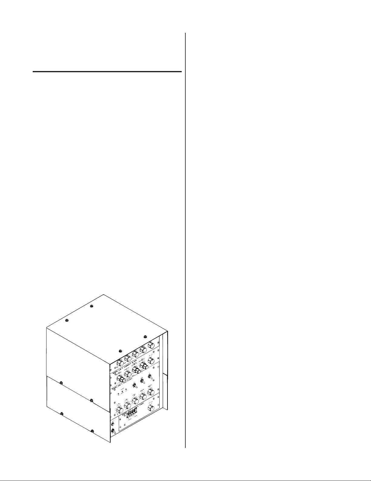
A-02401
Figure 2-1 Weld Sequencer Assembly
Manual 0-2023 9 INTRODUCTION & DESCRIPTION
Page 16

2.03 Specifications & Design Features
B. GS1 Gas Slope (Plasma)
1. Input Power
A. Weld Sequencer Enclosure
1. Input Power
115/230VAC, 1 Amp, 50/60 Hz
2. Control Circuit Output
28 VAC
3. Current Control
Up to 24 VDC using RP1 Control remote pendant
or some other external device.
4. Contactor Control
28 V control circuit using RP1 Control remote pendant or some other external device.
5. Control Console or Power Supply Control
Control is via 10' control cable.
6. Auxiliary Connections
Relay contacts and terminal connector provided
for auxiliary input/output signals (wire feeders,
motion controls, etc.).
7. Housing Capabilities
WT1 and/or GS1; WT1 and/or CS1 and/or CP1
NOTE
For a complete Sequencer Assembly, the Enclosure
Expansion must be added on top of the Weld Sequencer Enclosure to accommodate CS1 and CP1
modules. Also, the enclosure expansion is required
when WT1 or GS1 is used with either CS1 or CP1.
28 VAC from Weld Sequencer Enclosure
2. Plasma Gas Range
Min 0.5 - 3 scfh (0.25 - 1.4 lpm)
Max 2 - 7 scfh (1 - 3.3 lpm) @ 30 psi (2 bar)
3. Weight
9 lbs (4.05 kg)
C. CS1 Current Slope
1. Input Power
28 VAC from Weld Sequencer Enclosure
2. Weight
4 lbs (1.8 kg)
D. CP1 Pulser
1. Input Power
28 VAC from Weld Sequencer Enclosure
2. Pulse Rate
0.5 - 20 pulses/sec
3. Weight
3.5 lbs (1.58 kg)
E. WT1 Weld Timer
1. Input Power
28 VAC from Weld Sequencer Enclosure
2. Timing Control
8. Dimensions (W x H xD)
15 inches (381 mm) x 11 inches (279 mm) x 16-3/4
inches (425 mm)
With Enclosure Expansion height dimension is 18
inches (457 mm)
9. Weight
24.5 lbs (11.62 kg).
With Enclosure Expansion weight is 30 lbs
(14.23kg)
INTRODUCTION & DESCRIPTION 10 Manual 0-2023
Adjustable from 0.1 to 999.9 seconds
3. Weight
2.5 lbs (1.12 kg)
CAUTION
When using CS1 or CP1 with a power source other
than the Thermal Arc PS30A, the remote control
circuit must be 0 to +24 vdc and of a solid state
design.
Page 17
SECTION 3:
INSTALLATION
PROCEDURES
3.04 Equipment Installation General
WARNING
3.01 Introduction
This section describes installation of the Weld Sequencer.
These instructions apply to the Weld Sequencer only; installation procedures for the Power Supply, Welding Console, Torch, Options, and Accessories are given in Manuals specifically provided for those units.
The complete installation consists of:
1. Site selection
2. Unpacking
3. Connections to Weld Sequencer
4. Operator training
3.02 Site Selection
The Weld Sequencer Enclosure should be located either
next to or on top of the Welding Console (GS1 connections must be installed in Welding Console before mounting on top). A source of 115 or 230 VAC power must also
be available.
NOTE
Review Important Safety Precautions (page 1) to
be sure that the selected location meets all safety
requirements.
3.03 Unpacking
Make sure that all power to the welding system is
shut off at the incoming source. Do not turn ON
the power until all components are connected.
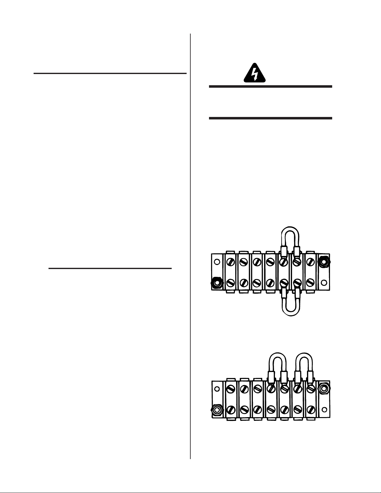
A. Voltage Selection
The Weld Sequencer Enclosure is factory-wired for 230V,
60Hz operation. If 230V primary power is available, connect the end of the input power cord to the 230V primary
power source.
If 115V primary power is to be used change TB4 connections as follows:
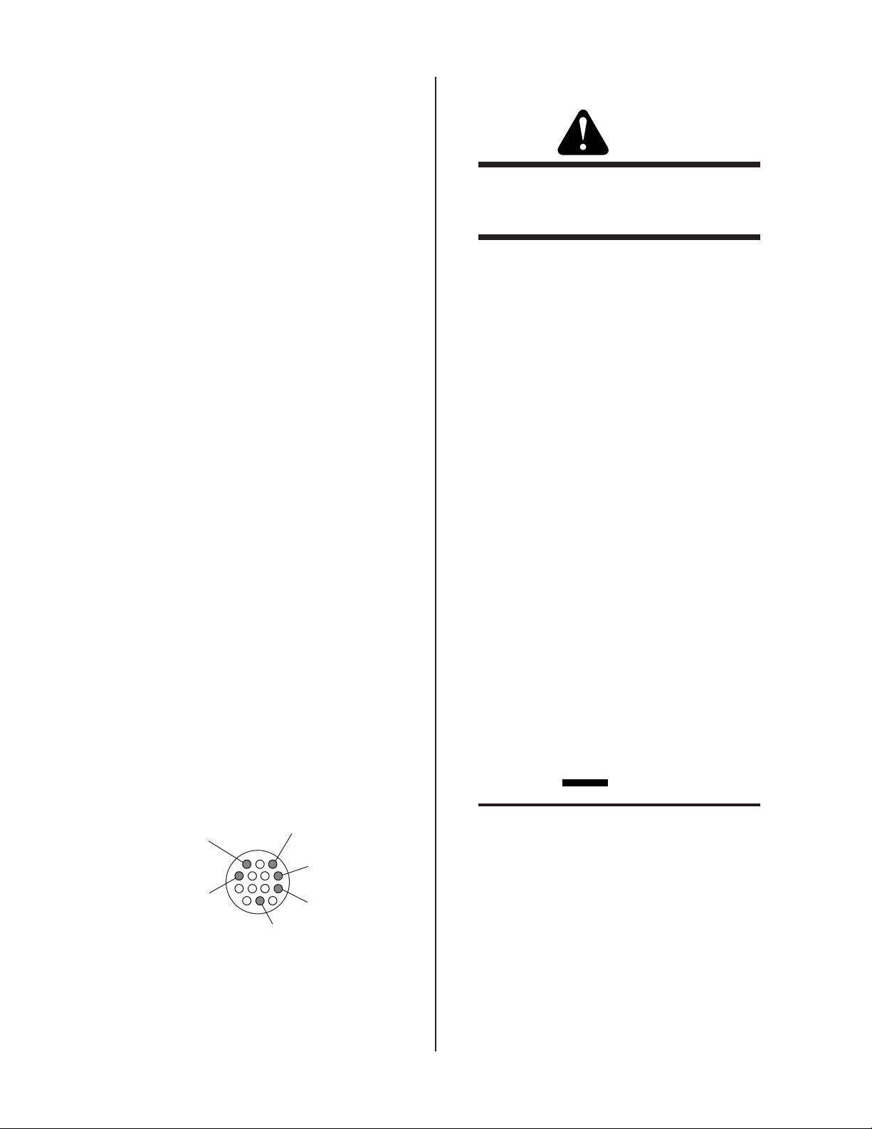
1. Locate TB4 terminal strip on the rear panel of the En-
closure. Remove the two jumpers from each side of
terminals 5 and 6.
230 Volt Jumpers
1 2 3 4 5 6 7
TB4 Terminal Strip
A-02404
Each component of the system is packaged and protected
with a carton and packing material to prevent damage
during shipping.
1. Unpack each item and remove all packing material.
2. Locate the packing list(s) and use the list to identify
and account for each item.
3. Inspect each item for possible shipping damage. If
damage is evident, contact your distributor and/or
shipping company before proceeding with system
installation.
Manual 0-2023 11 INSTALLATION PROCEDURES
Figure 3-1 Jumper Installation For 230 VAC Input
2. Connect one jumper across terminals 4 and 5 and the
other across 6 and 7.
115 Volt Jumpers
1 2 3 4 5 6 7
TB4 Terminal Strip
Figure 3-2 Jumper Installation For 115 VAC Input
A-02405
Page 18
3. Connect plug (supplied) to the end of the input power
cord per the following:
a. Feed the free end of the input power cable through
the small section of the rubber plug housing.
b. Connect the ground lead to the green terminal on
the plug.
c. Connect the other two leads to the two terminals
on the plug.
d. Press the plug into the rubber housing until the
plastic disk is captured by the rubber housing.
e. Tighten cord grip to secure input cable.
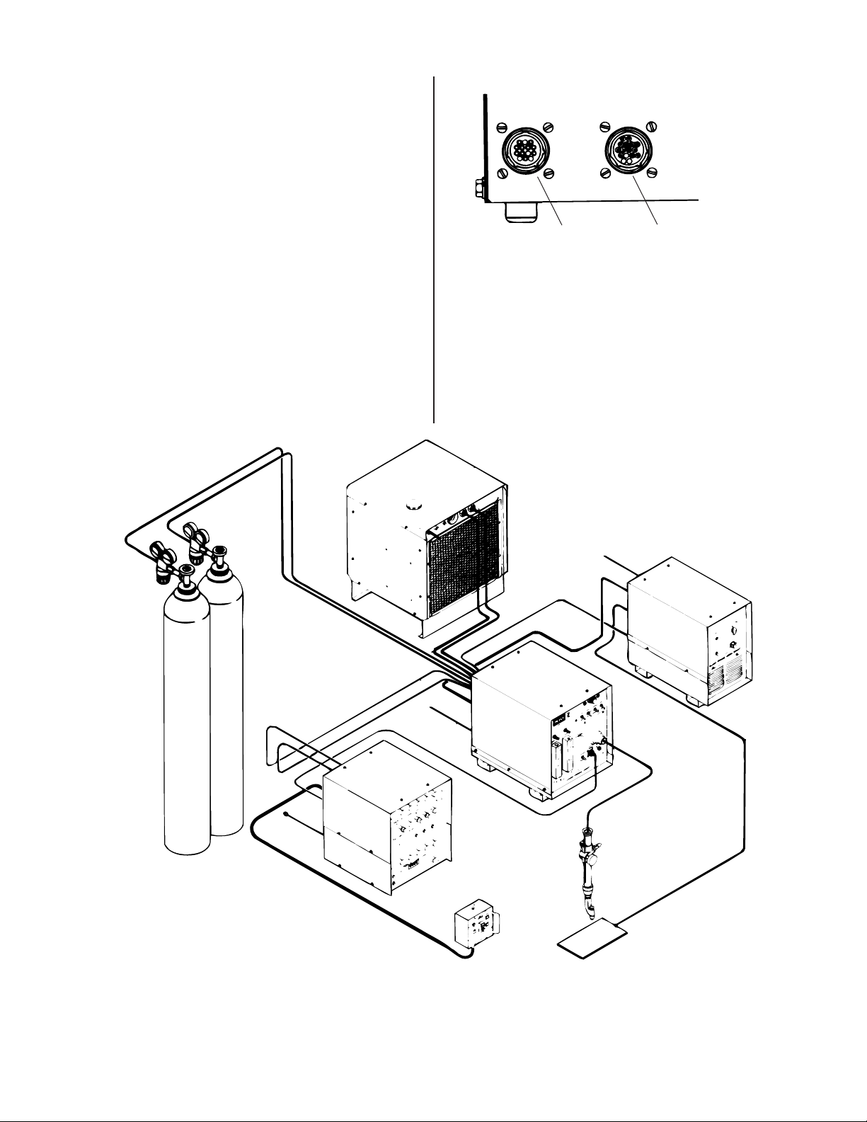
A-02406
REMOTE
CONTROL
Control Cable Console/Power Supply
CONSOLE/POWER SUPPLY
CONTROL
Control Cable
Figure 3-3 Weld Sequencer Enclosure Rear Panel
Connections
B. Cable Connections
1. Connect RP1 Control pendant to the connector on the
end of the 20 foot (6.1 m) Remote Control Cable. Connect the other end of the cable to the back of the Weld
Sequencer Enclosure marked REMOTE CONTROL.
Plasma Gas
If a different remote control device is to used refer to
the Wiring Diagram supplied with the Weld Sequencer. The current control potentiometer must be
rated for 10k ohm at 2 watts.
Coolant Recirculator
DC Power
Supply
Welding
Console
Weld
Sequencer
Shield Gas
Optional Remote
Control
A-02407
Torch
Figure 3-4 WC100B Connections
INSTALLATION PROCEDURES 12 Manual 0-2023
Page 19
2. Connect the mating plug of the 10 foot (3 m) Control
Cable to the receptacle on the rear panel of the Weld
Sequencer Enclosure marked CONSOLE/POWER
SUPPLY CONTROL.
3. The connection on the other end of the cable depends
on the welding console, power supply or current control device. Connect as follows (refer to Figure 3-4):
• Thermal Arc WC100B Welding Console
• Other Welding Consoles and Power Supplies
WARNING
The remote control circuit of the welding console
or power supply must not exceed 28 volts AC or
DC.
a. Connect Control Cable plug to the receptacle on
the front panel of the WC100B marked REMOTE
CONTROL. Move REMOTE ON/OFF switch to
ON position.
• Thermal Arc WC100A and WC122A (and earlier
models) Welding Consoles
b. Cut the Control Cable plug off and strip cable jacket
back approximately 2 inches.
c. Locate the cable from the welding console CON-
TROL receptacle. Measure enough cable to connect with the Control Cable from the Weld Sequencer Enclosure and cut.
d. Connect the white/brown (J5-3) and black (J5-4)
wires of the Weld Sequencer Enclosure Control
Cable to the two leads of the cable from the welding console CONTROL. The order of connection
is unimportant. This connection gives contactor
control to the Sequencer.
e. Connect a cable to the Remote Amperage Control
of the power supply. Connect the other end to the
Weld Sequencer Enclosure Control Cable (see Figure 3-E):
Power Supply Amperage Control maximum lead
to orange wire (J5-1)
a. Cut the cable plug off. Strip the cable jacket back
approximately 2 inches.
b. Connect the white/brown (J5-3) and black (J5-4)
wires of the Weld Sequencer Enclosure Control
Cable to the contactor control of the welding unit.
This gives contactor control to the Sequencer.
c. Connect a cable to the Remote Amperage Control
of the power supply. Connect the other end to the
Weld Sequencer Enclosure Control Cable (refer to
Figure 3-5):
Power Supply Amperage Control maximum lead
to orange wire (J5-1)
Power Supply Amperage Control variable (wiper)
lead to red wire (J5-7)
Power Supply Amperage Control minimum lead
to blue wire (J5-13)
d. Tape back the wires not used.
e. Check input power connections on the terminal
strip TB4, located on the rear panel of the Weld
Sequencer Enclosure, to be sure that they are set
up for the available voltage. Provisions are made
for primary inputs of 115 or 230 volts AC (refer to
Section 4.2) and 50 or 60 Hz power may be used.
Power Supply Amperage Control variable (wiper)
lead to red wire (J5-7)
Power Supply Amperage Control minimum lead
to blue wire (J5-13)
Contactor
Control
AMP Control
(Wiper)
A-02408
3
7
13
AMP Control
1
AMP Control
(Max)
4
Contactor
Control
8
Ground
(Min)
Figure 3-5 Back View of Control Cable Plug
3.05 WT1 Weld Timer
CAUTION
The WT1 Weld Timer is factory set for 60 Hz operation. If 50 Hz power is used or WT1 doesn’t
time properly remove the cover from WT1 and check
the position of the switch mounted in the middle of
the PC board. Move the handle to the proper position printed on the PC board (50 or 60).
1. Install WT1 into the bottom of the opening in the Weld
Sequencer Enclosure (refer to Figure 3-6). Secure with
screws provided.
2. Connect WT1 to the Weld Sequencer Enclosure wiring
f. Tape back the wires not used.
harness with the J4 connectors.
Manual 0-2023 13 INSTALLATION PROCEDURES
Page 20
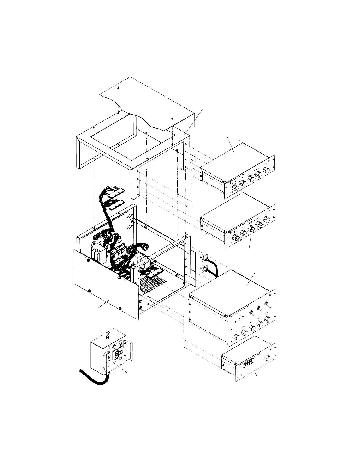
A-02409
Enclosure Expansion
CP1 Pulser
J7
J8
J3
CS1 Current Slope
Weld Sequencer
Enclosure
GS1 Gas Slope
J4
RP1 Control
WT1 Weld Timer
Figure 3-6 Weld Sequencer Assembly
INSTALLATION PROCEDURES 14 Manual 0-2023
Page 21

3.06 GS1 Gas Slope
1. Install PLASMA IN and OUT fittings from the back of
GS1 through the opening in the front of the Weld Sequencer Enclosure and secure to the rear of the Enclosure.
PLASMA
Gas IN
2. Install GS1 into upper opening of the Enclosure (refer
to Figure 3-6) and secure with screws provided.
3. Connect GS1 to the Weld Sequencer Enclosure wiring
harness with the J3 connectors.
NOTE
If CS1 and/or CP1 are not used then the jumper
connectors must be installed in wire harness connector J8 (CS1) and/or connector J7 (CP1). If this
is not done the current control will not function
properly.
4. Install GS1 adapter fitting assembly into the welding
console between the flowmeter and the plasma gas
torch connection. For installation in Welding Consoles
WC100A, WC100B and WC122A (refer to Figures 3-8,
3-9, and 3-10).
PLASMA
Gas OUT
A-02410
Figure 3-7 GS1 Plasma Connections
To To r ch
3.
Remove
1.
Disconnect this tube
and move up and out
of the way. Reconnect
after assembly is complete.
this fitting.
5. Feed plasma gas hoses from the adapter fitting assembly through the plastic bushing on the rear panel of
the welding console.
6. Open plasma gas flow valve on the welding console
all the way.
2.
Disconnect Tube
From Plasma Gas Metering Valve
4.
Add sealant to threads and screw
in assembly to position shown.
From Source
5.
Remove
this nut.
6.
Reconnect plasma
gas supply hose.
Bold arrows indicate direction of flow
A-02411
From GS1
To GS1
Figure 3-8 GS1 Connections to WC100A and WC122A (with copper tubing)
Manual 0-2023 15 INSTALLATION PROCEDURES
Page 22

To To r c h
2.
Remove these two fittings.
3.
Apply sealant to these threads
and screw in assembly to
position shown.
Bold arrows indicate direction of flow
1.
Cut tubing off at end of fittings.
From Plasma Gas Metering Valve
5.
Push tubing into fitting
and hand tighten, then
3/4 turn more.
If tubing in step 1
is too short, use the
one supplied with the
assembly.
4.
Push insert
into tubing.
From Source
A-02412
Figure 3-9 GS1 Connections to WC122A (with plastic tubing)
To To r ch
2.
Remove these two fittings.
3.
1.
Cut tubing off at end of fittings.
Apply sealant to these threads
and screw in assembly to
position shown.
From Plasma Gas Metering Valve
5.
Push tubing into fitting
and hand tighten, then
3/4 turn more.
From GS1
If tubing in step 1
is too short, use the
one supplied with the
assembly.
4.
Push insert
into tubing.
To GS1
From Source
Bold arrows indicate direction of flow
A-02413
From GS1
To GS1
Figure 3-10 GS1 Connections to WC100B
INSTALLATION PROCEDURES 16 Manual 0-2023
Page 23

3.07 CS1 Current Slope
1. Install CS1 into the bottom of either the Weld Sequencer
Enclosure or the Enclosure Expansion (see NOTE) and
secure with screws provided.
NOTE
If CP1 and/or CS1 are used without GS1 they are
mounted in the Weld Sequencer Enclosure. When
either or both are used with the Gas Slope the Enclosure Expansion must be mounted to the top of
the Weld Sequencer Enclosure (refer to Figure 3-6).
CP1 and CS1 are then mounted in the Enclosure
Expansion.
2. Connect CS1 to the Weld Sequencer Enclosure wiring
harness with the J8 connectors.
3.08 CP1 Pulser
1. Install CP1 into Weld Sequencer Enclosure or Enclosure Expansion above CS1 (if included) and secure
with screws provided.
2. Connect CP1 to the Weld Sequencer Enclosure wiring
harness with the J7 connectors.
NOTE
When spot welding using automated control devices (and only if RP1 Remote Pendant is used)
the jumper across TB3-2 to TB3-3 must be removed
(refer to Appendix III).
3.09 Automatic Voltage Control
(AVC) Lockout
When using CP1 on systems having Automatic Voltage
Control (AVC) it is necessary to inhibit AVC when CP1 is
not at peak voltage so that the AVC does not try to track
the voltage change due to pulsing. Since it is possible
that the power supply ground of the AVC unit will not be
common to that of the Weld Sequencer the circuit to supply the 'inhibit' signal is electrically isolated from CP1 by
an optoisolator.
The ground and supply voltage for the isolation circuit
must be supplied from the AVC (refer to Appendix III).
Supply voltage can be from +5 to +15 vdc. The AVC 'inhibit' signal is low, or not inhibited, when the CP1 is at
peak voltage, and high, or inhibited (equal to supply voltage), during the rest of the cycle.
3.10 Auxiliary Connections For
Interfacing External Controls
There are three terminal strips provided on the base of
the Weld Sequencer Enclosure for interfacing the Sequencer with other components or controls(refer to Appendix I and III for available locations and signals). Relay AL de-energizes at the end of upslope and re-energizes
at the start of downslope. The CC relay signals contactor
closure and de-energizes during welding sequence.
Manual 0-2023 17 INSTALLATION PROCEDURES
Page 24

INSTALLATION PROCEDURES 18 Manual 0-2023
Page 25

SECTION 4:
OPERATION
4.01 Introduction
4.03 Weld Sequencer Enclosure Control Descriptions
This section provides a description of the Power Supply
operating controls and procedures. Identification of the
Front and Rear Panel components is followed by operating procedures.
4.02 Functional Overview
The Weld Sequencer is designed to automatically control
the output of most solid-state power supplies. The Weld
Sequencer gives the operator more accurate control of the
variables within a welding operation. Once the Weld Sequencer is programmed for a particular welding operation, the weld can be reproduced with minimal fluctuations. Four separate solid-state control modules, a Weld
Sequencer Enclosure and a RP1 Control remote pendant
make up the Weld Sequencer. Any combination of the
four modules can be used with the Weld Sequencer Enclosure to be a stand-alone unit.
CP1
PULSE RATE
5
4
3
2
1
0
CS1
INITIAL
CURRENT TIME
5
4
3
2
1
0
GS1
MIN
PULSER
PERCENT ON TIME
5
4
6
7
3
2
8
1
9
0
10
CURRENT SLOPE
UPSLOPE RATE
4
6
7
3
8
2
9
1
10
0
0 - 10 sec.
GAS SLOPE
GAS FLOW
SLOPING
MAX
PULSE SLOPE
BACKGROUND CURRENT
5
5
4
4
6
6
7
7
3
3
2
2
8
8
9
10
5
6
7
8
9
10
weld time
1
0
DOWNSLOPE
DELAY RATE
5
4
3
2
1
0
0 - 10 sec.
UP
DOWN
10
6
7
10
1
9
0
(pull for display)
CURRENT TIME
3
2
8
1
9
0
0 - 10 sec.
4
MANUAL
FINAL
5
AUTO
ONOFF
6
7
8
9
10
ONOFF
6
7
8
9
10
ON
OFF
2
1
A-02415
Figure 4-2 Weld Sequencer Enclosure
1. ON/OFF Switch
Activates Weld Sequencer Enclosure power circuits
and supplies AC power to all Sequencer Controls in
ON position. In the OFF position deactivates all Sequencer Control circuits.
2. Red AC Power Light
Indicates that AC power is being supplied to the Sequencer control modules.
DOWNSLOPE
DOWNSLOPE
RATE
DELAY
5
4
3
0
5
4
6
6
7
7
3
2
8
8
1
9
0
(0 - 10 sec.)
9
10
ONOFF
10
AC POWER
A-02414
MAX
GAS FLOW
4
2 - 7 SCFH
1 - 3.3 lpm
5
6
WT 1
7
8
9
10
SECONDS
UPSLOPE
RATE
5
4
6
3
2
1
0
WELD TIMER
TENTHS
7
2
8
1
9
10
MIN
GAS FLOW
5
4
6
7
3
3
2
2
8
1
1
9
10
0
0
.5 - 3 SCFH
.25 - 1.4 lpm
ON
OFF
Figure 4-1 Control Modules Assembled In Weld
Sequencer Enclosure
Manual 0-2023 19 OPERATION
Page 26

4.04 RP1 Control Descriptions
Start of
downslope
Start of upslope
Weld Time
(0.1 - 999.9 sec)
A-02421
4.05 WT1 Weld Timer Control Descriptions
1
CONTACTOR
ON
5
OFF
SPOTWELD
RP 1
CONTROL
WELD
CURRENT
START
SEQUENCE
START
DOWNSLOPE
3
A-02416
Figure 4-3 RP1 Control
1. Contactor ON/OFF Switch
Activates main contactor closure in power supply to
prepare for start of weld sequence. Must be in the
OFF position before turning sequencer to OFF position.
12
WT 1
SECONDS
WELD TIMER
ONOFF
TENTHS
4
A-02417
2
Figure 4-4 WT1 Weld Timer
1. ON/OFF Switch
In OFF position WT1 is disabled. The ON position energizes timing circuits.
2. SECONDS-TENTHS Dial
Allows weld time to be set in seconds to the tenth of a
second up to 999.9. When WT1 is used with CS1 timing starts with start of upslope and times out to automatically initiate downslope sequence.
2. Weld Current
Allows welding current to be adjusted within the
range set on the power supply. Can be used to set CS1
and CP1.
3. START SEQUENCE Switch
Activates sequence of CS1 and GS1 only. When GS1
is used independently, pressing switch will start
plasma gas 'upslope' sequence.
4. START DOWNSLOPE Switch
Allows manual start of plasma gas and current
'downslope' sequence.
5. SPOTWELD Switch
Allows contactor closure to be initiated at operators
discretion after the first spot weld sequence has been
completed (if the CONTACTOR ON/OFF switch is
left in ON position).
CAUTION
WT1 is set for operation on 60Hz power. For 50Hz
operation the timer must be reset (refer to Section
3.05 for 50Hz).
OPERATION 20 Manual 0-2023
Page 27

4.06 CS1 Current Slope Control Descriptions
A-02418
CS1
INITIAL
CURRENT TIME
5
4
3
2
1
0
0 - 10 sec.
CURRENT SLOPE
UPSLOPE RATE
5
4
6
6
7
3
8
2
9
1
10
0
weld time
7
8
9
10
DOWNSLOPE
DELAY RATE
4
3
2
1
0
0 - 10 sec.
5
6
7
8
9
10
FINAL
CURRENT TIME
5
4
3
2
1
0
0 - 10 sec.
6
7
8
9
10
23 4 5
ONOFF
1
3. UPSLOPE RATE Control
Peak Current
Initial
Current
Upslope
Distance
(Amps)
Figure 4-5 CS1 Current Slope
1. ON/OFF Switch
In OFF position CS1 is taken out of the welding operation. The ON position energizes the circuitry.
2. INITIAL CURRENT/TIME Control (Dual Control
Pot)
INITIAL CURRENT Control (inner knob) allows setting of desired starting current from which upslope
will begin. This setting is the percentage of the difference between MAX (determined by RP1 weld current
setting) and MIN of the Power Supply current range.
Add the value of this percentage to the MIN current
to determine actual current level.
MIN
Current
Initial Current
A-02423
Time
(seconds)
Determines rate at which current slopes up from initial setting to MAX setting. The numbers are reference points and have no predetermined value. Zero
setting reflects the slowest slope rate for a particular
current range and ten relects the fastest (refer to Figure 4-8 for details).
4. DOWNSLOPE DELAY/RATE Control
Delay Start Downslope
Start Downslope
Signal
Distance
(Amps)
(0 - 10 sec)
Downslope
Initial Current
A-02422
Time
EXAMPLE
A Power Supply set at a range of 25 to 125 amps
has a difference of 125 - 25 = 100 amps. A 50%
setting is equal to 100 X 50% = 50 amps, + 25
amps min = 75 amps initial current.
A-02424
A dual control potentiometer that controls the
Downslope Delay and the Rate. The RATE control
(outer knob) determines the rate at which the current
slopes down from MAX setting to final current setting. The numbers are reference points and have no
Time
(seconds)
predetermined value. Zero (0) setting reflects the
TIME control (outer knob) sets the desired initial current time before activating the upslope sequence. It is
variable between 0-10 seconds as represented by the
numbers around the knob.
slowest slope rate for a particular current range while
ten (10) reflects the fastest rate (refer to Figure 4-8 for
details). The DELAY control (inner knob) allows the
actual start of downslope current to be delayed from
0-10 seconds after the downslope is initiated.
Manual 0-2023 21 OPERATION
Page 28

5. FINAL CURRENT/TIME Control
Final Current
Time
A-02425
A
A
One Pulse
Time
B
B
A-02426
EXAMPLE
Ten pulses in one second means that the distance
from point A to point B is traveled ten times in one
second (10 pulses/second or 600 pulses/minute)
A dual control potentiometer that controls the Final
Current and the Time. The FINAL CURRENT control (inner knob) sets welding current at the finish of
the weld. Like the INITIAL CURRENT it is a percentage of the set operating current range of the Power
Supply (maximum current setting determined by RP1)
and is added to the minimum current to arrive at a
amperage value.
The FINAL TIME control (outer knob) sets the length
of time that the final current will be maintained before signaling the contactor to open, ending the weld.
The numbers around the knob refer to seconds.
4.07 CP1 Pulser Control Descriptions
A-02419
CP1
PULSER
PULSE RATE
PERCENT ON TIME
5
4
6
7
3
2
1
0
3
2
8
1
9
0
10
PULSE SLOPE
5
4
6
7
8
9
10
BACKGROUND CURRENT
5
4
3
2
1
0
5
4
6
7
10
8
9
3
2
1
0
(pull for display)
6
234 5
7
10
ONOFF
8
9
1
3. PERCENT ON TIME Control
Percent ON
Time Setting
75% 25%
One Pulse
Peak Current
Background
Current
A-02427
Sets the amount of time the peak current is on relative
to the amount of time background current is on, in
any one pulse. Settings are in percent, not actual time.
A setting of 50% means peak current is on the same
amount of time as the background current. A setting
of 75% means peak current is on three times longer
than background current.
4. PULSE SLOPE Control
Gradual
Change
Peak Current
Figure 4-6 CP1 Pulser
A-02428
1. ON/OFF Switch
Background Current
In OFF position CP1 is disabled. In the ON position
its circuitry is energized.
Allows gradual change in current between background current and peak current levels during puls-
2. PULSE RATE Control
Regulates the number of pulses (time taken to go from
point A to point B) in a given time period. Numbers
ing.
5. BACKGROUND CURRENT Control (pull for display)
are for reference only and do not indicate pulses per
second.
Adjusts lower level of current. Can be adjusted while
pulsing by turning the knob. Numbers around knob
refer to the percentage of Power Supply output current range and should not be taken as an amperage
value.
OPERATION 22 Manual 0-2023
Page 29

EXAMPLE
NOTE
A Power Supply set in a range of 50 - 150 amps
with a background current of 30% would be 150 50 = 100 amps total range 100 amps x 30% = 30
amps 30 amps + 50 amps min = 80 amps background.
A-02429
Background Current
To adjust background current with an ammeter while
doing a test weld, pull the knob out. CP1 will cease to
pulse and will maintain weld current at background
current level. Adjust to new background current by
turning knob (checking ammeter on console or power
(supply). Push back in to resume pulsing operation.
NOTE
An auxiliary connection is available to start or stop
the CP1 without stopping the weld sequence (see
AVC LOCKOUT, refer to Section 3.09).
4.08 GS1 Gas Slope Control Descriptions
CS1 will not operate with GS1 in MANUAL position. In AUTO position the gas slope sequence will
automatically be controlled by signals from the CS1
Control circuitry only.
3. UP/DOWN Switch
With the MANUAL/AUTO switch in MANUAL position the UP/DOWN switch (see NOTE) is used to
start upslope (UP) and downslope (DOWN) of gas
flow. The rate of slope is determined by the sloping
control settings. In AUTO position, the UP/DOWN
switch is disabled.
NOTE
Refer to Section 4.04, RP1 Control, for Remote
Up/Down Control.
4. GAS FLOW MIN/SLOPING/MAX LED
These three LEDs light to indicate the status of gas
flow during a weld.
5. MIN GAS FLOW Control
Adjusts minimum gas flow rate, 0.5 - 3 scfh (0.25 - 1.4
lpm). The numbers surrounding the knob are reference points only and have no set value.
6. MAX GAS FLOW Control
1
234
GS1 GAS SLOPE
2
1
3
0
.25 - 1.4 lpm
MIN
MIN
GAS FLOW
4
.5 - 3 SCFH
GAS FLOW
SLOPING
MAX
MAX
GAS FLOW
5
5
4
6
6
7
7
3
0
2 - 7 SCFH
1 - 3.3 lpm
3
2
8
1
9
10
0
2
8
1
9
10
UP
DOWN
UPSLOPE
RATE
4
MANUAL
AUTO
DOWNSLOPE
RATE
5
4
6
3
7
2
8
1
9
0
10
ON
OFF
DOWNSLOPE
DELAY
5
5
4
6
6
7
7
3
2
8
8
1
9
0
(0 - 10 sec.)
9
10
10
A-02420
98765
Figure 4-7 GS1 Gas Slope
1. ON/OFF Switch
In OFF position GS1 is disabled and gas flow remains
at its last setting. The ON position energizes its circuitry.
2. MANUAL/AUTO Switch
MANUAL position allows the operator to manually
control gas slope sequence for setup and also during
the welding operation.
Adjusts maximum gas flow rate, 2 - 7 scfh (1 - 3.3 lpm).
The numbers surrounding the knob are reference
points only and have no set value.
7. UPSLOPE RATE Control
Controls the rate (time) for gas flow to increase from
minimum flow to maximum. This is done by trial
and error in pre-setup. The numbers surrounding the
knob are reference points only and do not indicate
time (0 slowest, 10 fastest). Refer to Figure 4-10 for
details.
8. DOWNSLOPE RATE Control
Controls rate (time) for gas flow to decrease from
maximum flow to minimum. This is done by trial and
error in pre-setup. Numbers surrounding the knob
are reference points only and do not indicate time (0
slowest, 10 fastest). Refer to Figure 4-10 for details.
9. DOWNSLOPE DELAY Control
Allows the start of gas downslope to be delayed for a
predetermined amount of time (0 to 10 seconds) after
downslope is initiated either manually or by WT1.
Numbers surrounding the knob correspond to seconds.
Manual 0-2023 23 OPERATION
Page 30

4.09 Pre-Operation Setup
A. General
1. Follow all pre-operation set-up procedures required
in the Welding Console and Power Supply instruction manuals.
2. Move the ON/OFF switch on the Weld Sequencer En-
closure to the ON position.
WARNING
The RP1 Control CONTACTOR ON/OFF switch
must be in the OFF position before the Weld Sequencer Enclosure or any control module is shut
off. If this is not done and the torch is close enough
to the workpiece (or ground) when the system is
energized an arc transfer can take place.
CAUTION
Pre-operation setup of each module can be done independently from the others but it must be kept in
mind that when actual welding sequence begins
some controls depend on others for proper operation. For instance, the rate of plasma gas flow must
correspond to the current level at any given time
or tip damage could occur.
NOTE
Initial current must be within the range selected
on the power supply.
EXAMPLE
A. The power supply is set in a range of 25 to 125
amps and the desired initial current is 30 amps.
This value is 5 amps above the MIN range of
25 amps (30-25 min = 5).
B. Full current range is 125 amps MAX - 25 amps
MIN = 100 amps.
C. The 5 amps above MIN (25 amp) setting di-
vided by the 100 amp range equals the percentage setting of the INITIAL CURRENT (inner)
knod (5 ÷ 100 = 0.05 or (5%). Set knob on 5
(5%).
3. Set initial current time from 0 to 10 seconds using the
outer knob on the INITIAL CURRENT/TIME control.
The numbers correspond directly to the time in seconds.
4. Set final current at which downslope will end. Final
current value is determined the same as in Step 2
above and is set using the inner FINAL CURRENT
knob.
5. Adjust UPSLOPE RATE control while test welding until
the desired upslope is obtained or use Figure 4-8. Note
the number corresponding to the knob position for
future reference.
3. If GS1 is installed but not being used, set gas flow with
GS1 first then turn GS1 OFF.
4. CS1 and CP1 controls are adjusted within the current
range selected on the power supply (determined in
Step 1). Some control settings can be made only by
trial and error during sample welding operations.
B. CS1 Current Slope
CAUTION
The sloping current must stay within the acceptable range of plasma gas flow rate to prevent tip
damage (current too high) or insufficient penetration (current too low).
1. Move the ON/OFF switch to the ON position.
2. Set the starting current from which upslope will begin
and the percentage of difference between adjusted
MAX (as set on RP1 WELD CURRENT) and MIN of
the power supply range and adjust the inner knob
(INITIAL CURRENT) to obtain the desired current
level.
6. Adjust DOWNSLOPE RATE control while test welding until the desired downslope is obtained (or use
Figure 4-8). Record the number corresponding to the
knob position for future reference.
7. Set final current time from 0 to 10 seconds using the
outer knob on the FINAL CURRENT/TIME control.
The numbers correspond directly to the time in seconds.
Final Current
Time
A-02425
8. Adjust DOWNSLOPE DELAY (inner) knob to the desired delay 0 to 10 seconds as indicated by the numbers.
OPERATION 24 Manual 0-2023
Page 31

Downslope Delay
(0 - 10 sec)
A-02431
3. Determine the relationship required of peak current
on time versus background current on-time in percent. Set the PERCENT ON TIME knob to the appropriate number (1 = 10%, 5 = 50%, etc).
Downslope Signal
Initiated
C. CP1 Current Pulser
1. Move ON/OFF switch to the ON position.
2. Adjust the PULSE RATE control knob to set desired
pulses per second (clockwise rotation increases pulse
rate).
A-02432
One Pulse
10
9
One Pulse
50%
Peak ON
50%
Background ON
5
6
4
3
2
1
0
7
8
9
10
75%
Peak ON
25%
Background ON
5
6
4
3
2
1
0
A-02433
7
8
9
10
NOTE
When sloping the pulse, PERCENT ON TIME of
peak current is not proportional to background
current on-time.
A-02430
8
vs. Slope Time For Different Slope Rates
(Same Upslope and Downslope)
7
6
5
Initial and Final Current Control Settings
4
Rate = 10
Rate = 9
Rate = 8
Rate = 7
Rate = 6
Rate = 5
Rate = 4
Rate = 3
Rate = 2
Rate = 1
Rate = 0
3
2
Initial or Final Current Control Setting
1
0
0 5 10 15 20 25 30 35
Slope Time (seconds)
Figure 4-8 Upslope and Downslope Rates for Initial or Final Current Settings and Slope Times
Manual 0-2023 25 OPERATION
Page 32

SLOPE
Time
By Increa sing
PULSE RATE Decreases Unchanged Decreases Decreases
PERCENT ON TIME I ncreases Unchanged Decreases Unchanged
PULSE SLOPE Unchanged Decreases Unchanged Decreases
BACKGROUND CURRENT Unchanged Decreases Unchanged Decreases *
* = No change when Slope Rate set at MAX
ON Time
(Peak Current)
Peak Current
Background Current
Minimum Current
Total Pulse Time
On-Time
(Peak)
Slope Time
SLOPE
Time
ON Time
(Background Current)
On-Time
(Background)
A-02434
Total Pulse
Time
Figure 4-9 Adjusting CP1 Controls
D. WT1 Weld Timer
WT1 controls weld time from the start of upslope to the
start of the downslope (timed out) sequence when CS1 is
used. Calculate or determine the time by timing the sequence during a test weld.
When WT1 is used to time spot welds determine the 'time
on' of the weld. Contactor closure will activate the timer
for each spot weld. Make sure to shut CS1 off when spot
welding.
1. Set the SECONDS-TENTHS dial to the required weld
time.
2. Move the ON/OFF switch to the ON position to activate the timer.
3. Activate the RP1 CONTACTOR ON switch. One spot
weld sequence will be completed.
4. Press the RP1 SPOTWELD switch as required for additional welds.
4. Determine necessary background current and calculate the percent of the power supply range setting as
done for CS1 INITIAL CURRENT. If the welding console has an ammeter, while welding, set by pulling
the BACKGROUND CURRENT knob out and rotate
the knob until the desired amperage is read on the
ammeter. Push the knob back in.
5. While making a sample weld, adjust the PULSE SLOPE
control knob until the desired rate of change between
background and peak current is achieved.
Peak Current
Background Current
Pulse Slope
A-02435
WARNING
The RP1 Control CONTACTOR ON/OFF switch
must be in the OFF position before the Weld Sequencer Enclosure or any control module is shut
OFF. If this is not done and the torch is close
enough to the workpiece (or ground) when the
welding system is energized an arc transfer can
occur.
E. GS1 Gas Slope
1. Make sure plasma gas supply is turned on.
2. Make sure the welding console is in SET mode and
power is ON.
3. Move the GS1 ON/OFF switch to ON position.
4. Move the GS1 MANUAL/AUTO switch to MANUAL
position.
5. Move the GS1 UP/DOWN switch to DOWN position
(momentary)
CAUTION
Minimum sloping and maximum gas flow rates
must stay within the acceptable range of the current at each point to prevent tip damage (gas flow
too low) or cutting action (gas flow too high).
6. Adjust the MIN GAS FLOW knob until the required
minimum plasma gas flow rate is shown on the welding console flowmeter.
7. Move the GS1 UP/DOWN switch to UP position (momentary).
8. Adjust the MAX GAS FLOW knob until the required
maximum plasma gas flow rate is shown on the welding console flowmeter.
9. Adjust GS1 UPSLOPE RATE to correspond to current
upslope rate (if CS1 is used) or to achieve the desired
rate refer to Figure 4-10.
OPERATION 26 Manual 0-2023
Page 33

7
6
5
4
3
Max - Min Gas Flow (scfh)
2
Rate = 10
Rate = 9
Rate = 8
Rate = 6
Rate = 7
Rate = 5
Rate = 4
Rate = 2
Rate = 3
Rate = 1
Rate = 0
1
0
0
10
20
30
40
Time (Seconds)
Figure 4-10 GS1 Upslope and Downslope Rate Selection
10. Adjust GS1 DOWNSLOPE RATE to correspond to
current downslope rate (if CS1 is used) or to achieve
the desired rate refer to Figure 4-10.
11. Adjust delay time for the start of downslope using
the GS1 DOWNSLOPE DELAY knob. The numbers
specify delay time in seconds (from 0 to 10 seconds).
4.10 System Operation
NOTES
Refer to Appendix VI for timing and detailed sequence of operation for all Weld Sequencer Models.
A-02436
50
60
70 80 90 100
5. Move the RP1 Control CONTACTOR ON/OFF switch
to ON position to close the main contactor.
6. Push the RP1 Control START SEQUENCE switch to
start the welding sequence (see NOTES).
NOTES
1. If spot welding, once the CONTACTOR switch
is moved to ON position only the SPOTWELD
switch must be pressed to continue.
2. If GS1 is not used the entire weld sequence will
start with contactor closure and pressing the
START SEQUENCE switch. If GS1 is set in to
MANUAL, CS1 (if used) will not operate.
Refer to Appendix VII for timing and detailed sequence of operation for GS1 Gas Slope Only.
1. Position torch for start of weld.
2. Turn on gas supplies.
3. If CS1 is not used and GS1 is set to MANUAL,
start gas upslope by pressing the RP1 Control
START SEQUENCE switch. Start gas
downslope by pressing the RP1 Control START
DOWNSLOPE switch.
3. Activate welding console, coolant recirculator, power
supply, weld sequencer and any accessory control circuits.
4. Turn on all control modules in the weld sequencer that
are to be used.
Manual 0-2023 27 OPERATION
Page 34

OPERATION 28 Manual 0-2023
Page 35

SECTION 5:
CUSTOMER/OPERATOR
SERVICE
5.03 Troubleshooting Guide General Information
WARNING
5.01 Introduction
This Section provides service diagnostics for the Weld
Sequencer, allowing the Technician to isolate any faulty
Subassemblies. Refer to Subsection 5.05, Parts Replacement Procedures, for parts replacement instructions.
Under no circumstances are field repairs to be attempted
on Printed Circuit Boards or other Subassemblies of this
unit. Evidence of unauthorized repairs will void the factory warranty.
NOTE
The troubleshooting contained in this manual is
for the Weld Sequencer only. Troubleshooting other
parts of the system is covered in the separate manuals for that product.
5.02 Transformer Connections
The main transformer in the Weld Sequencer Enclosure
is compatible with input voltages of 115 and 230VAC. Selection is made on the terminal strip on the rear panel of
the Enclosure using two jumper terminals. Figure 5-1
shows the jumper locations for the different voltages.
230 Volt Jumpers
1 2 3 4 5 6 7
TB4 Terminal Strip
115 Volt Jumpers
1 2 3 4 5 6 7
TB4 Terminal Strip
Figure 5-1 Input Voltage Terminal Locations
A-02404
A-02405
There are extremely dangerous voltage and power
levels present inside this unit. Do not attempt to
diagnose or repair unless you have had training in
power electronics measurement and troubleshooting techniques.
A. Troubleshooting
This manual provides troubleshooting and parts replacement. In most cases, it requires Weld Sequencer disassembly and live measurements.
Troubleshooting and repair of this unit is a process which
should be undertaken only by those familiar with high
voltage high power electronic equipment.
If major complex subassemblies are faulty, the faulty subassembly must be returned for repair.
NOTE
Follow all instructions as listed and complete each
in the order presented.
Malfunctions may be due to faulty connections rather than
a faulty component. Check all connections to the components that appear to be malfunctioning. The troubleshooting guide is arranged in the normal operating sequence of the Weld Sequencer (refer to Appendix VI or
VII) for easy reference. Before troubleshooting is started,
the Weld Sequencer should be isolated from the system
to confirm that the problem exists in the Weld Sequencer
and not another part of the system. If a problem is in the
power supply, welding console, or other component of
the system, check their respective Manuals supplied with
that product.
The Weld Sequencer contains accessory components of
the welding system and consists of individual modules.
It is important to isolate the area of the trouble should
problems occur. The quickest way to identify whether
the problem is in the Weld Sequencer or one of the other
components of the welding system is to take the Weld
Sequencer out of the system by running GS1 GAS FLOW
up to the maximum flow desired, then shutting the GS1
module OFF. If CS1 and/or CP1 are connected they also
must be turned OFF. Try a weld. If the problem is corrected the fault is in the Weld Sequencer. If it doesn’t
correct the problem, the fault is probably in the welding
console, power supply or RP1 Remote Control. RP1 can
be isolated by switching the welding console and power
supply out.
Manual 0-2023 29 Section Name
Page 36

Subsection 5.04 includes specific test procedures, as referenced by the troubleshooting guide, for any specific
test(s) to be performed.
B. How to Use the Troubleshooting Guide
The following information is a guide to help the Service
Technician determine the most likely causes for various
symptoms. This guide is set up in the following manner:
B. Cannot set desired plasma gas flow rate (GS1 in
use)
1. GS1 not turned on
a. Turn on
2. Gas supply not turned on
a. Turn on
1. Perform operational check(s) on the equipment to isolate problem to possible circuit(s).
2. Determine symptom and isolate to defective assembly
using the following format:
System normal operational sequence and condition(s)
X. Symptom (Bold Type)
Any Special Instructions (Text Type)
1. Cause (Italic Type)
a. Check/Remedy (Text Type)
3. Locate your symptom in the appropriate.
4. Check the causes (easiest listed first) for the symptom.
5. Check the remedies listed for each cause.
6. Repair as needed being sure to verify that unit is fully
operational after any repairs.
NOTES
While troubleshooting visually inspect the internal components for signs of overheating, fractures
and damage.
With all components of the welding system ready for
operation, move the Weld Sequencer Enclosure ON/OFF
switch to the ON position. The red AC POWER light
comes ON.
A. No red AC POWER light
1. No input power
a. Check input power connections and fuses
2. Fuse 1FU blown
a. Check and replace
3. ON/OFF switch faulty
a. Check and replace
4. AC POWER light
a. Replace
3. GS1 set in AUTO using current slope
a. Switch to manual, adjust flow rates and switch
to AUTO sequence
4. Plasma gas metering valve in Welding Console not completely opened
a. Open valve completely
5. Incorrect gas supply pressure to console
a. Reset or replace regulator, check for gas leaks
6. Faulty GS1 PC board
a. Replace
7. GS1 motor/valve assembly out of calibration
a. Recalibrate, refer to Section 5.05-F
8. Blockage in hoses, console, or torch, restricting flow
a. Locate and repair
If CS1 is not on when the RP1 CONTACTOR switch is
moved to “ON” the power supply contactor closes and
the welding arc should transfer. If CS1 is used then the
welding arc is established when RP1 START SEQUENCE is pressed.
C. No welding arc transfer:
CS1 and WT1 not used, RP1 only used
1. CC Relay faulty or missing
a. Check and replace
2. RP1 contactor switch faulty
a. Check and replace
WT1 and RP1 used
3. WT1 faulty
a. Turn WT1 off, if arc transfers replace WT1 PC
Board. If not, refer to Section 5.04-B
CS1 and RP1 used
4. RP1 contactor switch not on before start sequence is
pressed
a. Switch to ON
Section Name 30 Manual 0-2023
Page 37

5. CS1 faulty
CS1 used, Initial or Final Current incorrect
a. Disconnect J8, connect to jumper plug, if arc
transfers replace CS1 PC Board. If no transfer,
refer to Section 5.04-C
GS1, CS1 & RP1 used
6. GS1 (if used) in MANUAL position
a. Switch to AUTO
D. Contactor stays on
CS1 and WT1 not used, GS1 and CP1 on or off
1. Console or power supply not switched to remote contactor control
a. Check & correct
2. RP1 contactor switch faulty
a. Replace
WT1 used. Contactor does not shut off at end of timing period but shuts off with RP1 contactor switch
3. Faulty CC relay
a. Check & replace; Refer to Setion 5.04-B
5. Improper setting or faulty CS1
a. Correct setting or replace CS1 PC Board
CP1 used, Welds at background current only (no
pulse)
6. BACKGROUND CURRENT knob (pull for display) is
pulled out
a. Push knob in
7. Faulty CP1 PC board
a. Replace
CS1 used, Welds at peak only
8. Background current set to same as peak
a. Set properly
9. Stop pulse signal applied at wrong time (J7-13, TB2-3
wire #22 connected to signal common wire #11 TB1-1,
2, 3, 4)
a. Remove stop pulse signal (refer to Appendix)
10. Faulty CP1 PC Board
4. Faulty WT1
a. Check per Section 5.04-A and replace WT1 PC
Board if necessary
CS1 used. Transfer occurs as soon as RP1 contactor
switch turned on, prior to start sequence
5. Faulty CC relay
a. Check replace
6. Faulty CS1
a. Replace CS1 PC board
E. No current control or incorrect current level
CS1 & CP1 not used
1. Power supply on wrong range
a. Set to proper range
2. Power supply or console not set to remote current
a. Set to remote
3. RP1 current control faulty
a. Check & replace (refer to Section 5.04-C)
4. If CS1 or CP1 not installed, J7 or J8 not plugged into
jumper plugs
a. Replace
F. At end of set initial current time current does not
start to increase
1. Initial current set same as weld current
a. Reset
2. CS1 faulty
a. Replace CS1 PC Board
G. Gas does not start to increase at end of set initial
current time
1. GS1 not ON
a. Turn GS1 to ON
2. Gas supply not on
a. Open supply valve
3. MIN gas flow set to close to MAX flow
a. Check MIN flow setting
4. Plasma gas control valve in welding console not opened
all the way
a. Open valve completely
5. Faulty GS1 valve
a. Install jumper(s)
Manual 0-2023 31 Section Name
a. Replace (refer to Section 5.05-F)
Page 38

6. Faulty GS1 PC Board
3. WT1 timer faulty
a. Replace
H. Torch tip blows during upslope sequence
1. Current slope too fast or gas slope too slow to maintain
proper arc characteristics
a. Check CS1 (refer to Section 4.06) and GS1 (refer
to Section 4.08) for proper adjustment
2. Gas leaks in system
a. Check and correct
3. Incorrect gas flow
a. Adjust
I. Welding arc cuts instead of maintaining keyhole
1. Current or gas flow too high to maintain proper keyhole
a. Adjust properly
J. Current doesn’t reach proper peak level (also see
Symptom 'D')
1. RP1 Weld Current set too low
a. Adjust RP1 to desired peak current
K. Plasma gas flow doesn’t reach desired maximum
rate
1. Plasma gas control valve in welding console not opened
all the way
a. Open valve completely
2. Plasma gas pressure incorrect
a. Adjust pressure check for leaks replace regula-
tor
a. Check and replace
4. CS1 PC Board faulty
a. Replace
M. Gas flow does not start to decrease
1. GS1 set for delay of downslope
a. Check GS1 DOWNSLOPE DELAY setting
2. GS1 PC Board faulty
a. Replace
N. GS1 or CS1 downslope not delayed when set for
delay
1. DOWNSLOPE DELAY circuit faulty
a. Replace PC Board in faulty module GS1 or CS1
At the end of the downslope sequence the current is at
the CS1 FINAL CURRENT set level and the gas flow at
the GS1 MIN flow setting. The CS1 FINAL TIME starts
timing. If keyhole welding the keyhole should be
closed at this point.
O. Keyhole weld not closing
1. MIN gas flow too high
a. Reduce flow rated
P. Current doesn’t reach final current level or goes
lower
1. CS1 FINAL CURRENT at wrong setting
a. Check and adjust
2. Faulty CS1 PC board
3. Faulty GS1 PC Board
a. Replace
4. GS1 Motor/Valve Assembly out of calibration
a. Recalibrate (refer to Section 5.05-F)
As the weld time set on WT1 times out, the start of CS1
and GS1 downslope is signaled. The AL relay is also
energized.
L. Current does not start to decrease
1. CS1 set for delay of downslope
a. Check CS1 DOWNSLOPE DELAY setting
2. WT1 not ON
a. Turn WT1 to ON
Section Name 32 Manual 0-2023
a. Replace
Q. Minimum gas flow too high or too low
1. GS1 MIN flow at a wrong setting
a. Check and adjust
2. Gas pressure incorrect
a. Reset or replace regulator or check for leaks
3. GS1 PC Board faulty
a. Replace
4. GS1 Motor/Valve Assembly out of calibration
a. Recalibrate (refer to Section 5.05-F
5. Blockage in hoses, console or torch restricting flow
a. Find and repair
Page 39

R. Using RP1 and CP1, spot welds are erratic with
varying penetration
1. CP1 on during spot welding
a. Turn CP1 to OFF
When the CS1 FINAL TIME times out the CC relay is
energized, opening the circuit to the main contactor in
the power supply. Welding arc is extinguished.
S. Welding arc does not extinguish
1. CC relay faulty
a. Replace relay
2. CS1 PC Board faulty
a. Replace
B. Checking Contactor Control
With the Weld Sequencer in OFF position and the RP1
CONTACTOR switch ON. Use an ohmmeter to check
for continuity from black to white/brown wires on the
console P/S cable J5-4 and J5-5. If there is no continuity,
check each component and wire in the contactor control
circuit diagram.
Console/Power
Supply Control
Cable
Black
J5-4
Weld
Sequencer
Enclosure
CC
2627
J6-4
Remote
Control
Cable
J9-4
RP1
ON
26
Contactor
OFF
At the end of the weld the RP1 CONTACTOR switch is
moved to the OFF position first to open the main contactor in the power supply. Then the Weld Sequencer
Enclosure is turned OFF along with the other components of the system.
T. Welding arc transfers when CS1, WT1 or Weld
Sequencer is turned OFF
1. RP1 CONTACTOR switch not OFF
a. Move RP1 to OFF
5.04 Test Procedures
WARNING
Some tests involve voltage measurements made
with power ON. Tests requiring voltage measurements are marked with this warning symbol. All
other tests are to be made with the primary system
power turned OFF.
White/Brown
J5-3
J6-3
J9-3
2828
A-02438
Figure 5-2 Contactor Control Circuit Diagram
C. Checking Current Control
With CS1 and CP1 turned OFF or J8 and J7 connected to
the jumper plugs and RP1 CURRENT CONTROL set to
minimum, check for continuity (approximately zero
ohms) from J5-7 (red wire) to J5-13 (blue wire), (refer to
Figure 5-3) with an ohmmeter set on “times 1000” scale.
Check for 10K (10,000) ohms from J5-7 to J5-1. Setting
RP1 CURRENT CONTROL to maximum will reverse the
readings (zero ohms between J5-7 and J5-1, and 10K ohms
between J5-7 and J5-13). If proper readings are not obtained check individual wire connections and components
to identify the fault.
The following tests are suggested for specific problems
listed in the troubleshooting guide. Letter designations
correspond to those listed in the remedy area of the guide.
A. Checking WT1
To test WT1 move the torch to about 1 inch (25.4 mm)
above the workpiece. Arc will not transfer but the gas
should go through the upslope sequence to max flow and
start to downslope at the end of set weld time (or at end
of downslope delay time). If this does not happen WT1
is faulty and must be replaced.
Manual 0-2023 33 Section Name
Page 40

Weld Sequencer Enclosure
CS1 or Jumper CP1 or Jumper
ON
ON
A-02439
Console/Power
Supply Control
High
Wiper
Low
Cable
Orange
J5-1
Red
J5-7
Blue
J5-13
OFF
J8-5 J8-6 J7-5 J7-6
20 20
TB3-4
11
21 23
24
1 2 3 4
TB1
Figure 5-3 Current Control Diagram
5.05 WT1 Weld Timer Parts Replacement Procedures
NOTE
Refer to Section 6.08 for parts list and overall detail drawing.
A. WT1 Timer Thumbwheel Switch
Replacement
1. Remove WT1 from Weld Sequencer Enclosure by re-
moving the four (4) outside button head screws on
the front panel (see Parts List)
2. Remove the WT1 cover.
3. Remove the four (4) screws that hold the timer switch
to the front panel. Use 3/64" hex wrench for the screw
head and 3/16" driver for the hex nut.
4. To remove the switch, press down on the large PC
board beside the two blue rectangular resistor assemblies while pulling up on the switch assembly until it
clears the white connector.
J6-1
J6-7
Remote
Control
Cable
J9-1
J9-7
J9-13
RP1
23
Max
24
11
Current
Control
(10K ohms)
Min
OFF
11
J6-13
2. Remove the ON/OFF switch knob by pulling straight
out. Remove the hex nut that secures the switch to the
front panel.
3. Remove the two screws securing the front of the PC
board to the two spacers.
4. Press each locking tab of the two plastic PC board supports inward and slide the PC board off.
5. Install the new PC board by reversing these steps.
C. CP1, CS1 & GS1 PC Board Removal
NOTE
Refer to Sections 6.05, 6.06 and 6.06 for parts list
and overall detail drawing.
1. Remove cover from the module
2. Disconnect the plug from the PC board.
3. Remove all the single knobs from the switches mounted
on the PC board by pulling straight out. Remove all
the concentric (dual) knobs (CS1 only) by loosening
the set screws securing each knob to the switch shaft.
5. Install the new switch by reversing the above steps.
B. WT1 PC Board Replacement
NOTE
Refer to Section 6.08 for parts list and overall detail drawing.
1. Remove the Timer Thumbwheel Switch per Section
5.05-A.
Section Name 34 Manual 0-2023
Page 41

Cover
PC Board
Connector
A-02440
Washer
Hex Nut
Knob
D. GS1 Motor/Valve/Pot Assembly
Replacement
NOTE
Refer to Sections 6.04 and 6.05 for parts list and
overall detail drawing.
The main components of the Motor/Valve/Pot Assembly are replaceable. These include the motor assembly,
valve assembly, pot assembly, pinion gear, and coupling.
The assembly can also be purchased complete. Replacement of the components require that GS1 be removed
from the Weld Sequencer. Proceed as follows:
1. Disconnect all power to the welding system.
2. Remove cover or side panels (enclosure extension).
3. Remove the two welding console plasma gas hoses
from the rear of the Weld Sequencer Enclosure. Remove the four screws holding the GS1 gas hose connectors to the Enclosure rear panel.
4. Remove connector from the rear of GS1.
5. Remove the four screws securing GS1 to the front of
the Weld Sequencer Enclosure.
Figure 5-4 Typical PC Board Removal
4. Remove all the hex nuts securing Figure 4-D Typical
PC Board Removal (CP1, CS1 and GS1)
5. Press the locking tab on each PC board support and
raise the board past the locking position to allow removal of the board.
6. Install the PC board (component side up) into the
switch mounting holes in the front panel. Press the
board down onto the supports until it snaps into the
locking tabs.
7. Secure the switches to the front panel with supplied
hex nuts.
8. Position knobs on the flats of the switch shafts and
push on.
9. Connect plug(s) to connector(s).
10. Replace module cover and secure.
6. Slide GS1 out of the Weld Sequencer Enclosure.
7. Remove the cover from GS1.
8. Disconnect the two connectors (motor and pot) on the
Motor/ Valve/Pot Assembly.
9. Remove the four screws securing the Assembly to the
GS1 rear panel.
If the complete Motor/Valve/Pot Assembly is to be
replaced go to Section 5.05-H.
E. Coupling, Pinion Gear, Pot Assembly and
Motor Assembly Replacement
NOTE
Refer to Section 6.05 for parts list and overall detail drawing.
1. If the motor assembly is to be replaced loosen the two
1/16" hex set screws securing the coupling to the
motor assembly. If the coupling or pinion gear is to be
replaced loosen the two 1/16" hex set screws securing the coupling to the pinion gear.
2. Remove the four screws from the motor assembly and
remove the motor and coupling, leaving the pinion
gear in place
Manual 0-2023 35 Section Name
Page 42

NOTES
11. Slide the valve assembly out of the slot in the bracket.
If the pinion gear is left engaged with the two other
gears the assembly will not require calibrating after assembly.
If the pinion gear is to be replaced try to keep both
gears from rotating until the new gear is installed.
3. Remove the pinion gear by pulling straight out (see
NOTE above).
4. Slide new pinion gear into teeth of valve and pot gears
(not rotating more than one tooth) and into bushing
on valve/pot bracket.
5. Slide the new coupling onto the motor shaft. Do not
tighten.
6. Guide the coupling end of the motor through the hole
in the motor mounting bracket. Align the motor and
pinion shafts and slide coupling onto the pinion gear
shaft until both shafts are engaged in the coupling.
7. Secure the new motor assembly to the bracket with
the connector toward the lower inside corner of the
mounting bracket.
8. Slide the coupling up against the pinion gear and secure all four set screws.
12. Disconnect the two hoses from the valve assembly.
Use a wrench to hold the elbow fitting.
13. Add pipe sealant to the two hose fittings and install
on the new valve assembly. Make sure hoses are
through the holes in the GS1 rear panel.
14. Back GS1 up to the right side of the Weld Sequencer
Enclosure and
a. Connect the Weld Sequencer Enclosure J3 plug to
the rear of GS1.
b. Connect the upper gas hose from the valve assem-
bly to the PLASMA IN hose from the Welding
Console
c. Connect the lower gas hose from the valve assem-
bly to the PLASMA OUT hose from the Welding
Console.
d. Reconnect the motor assembly and pot assembly
plugs to the GS1 wiring harness.
15. Turn on the power to the system.
16. Put Welding Console in SET position.
17. Turn Weld Sequencer Enclosure to ON position.
F. Valve Assembly Replacement
NOTE
Refer to Section 6.05 for parts list and overall detail drawing.
1. Disconnect all power to the welding system.
2. Remove cover or side panels (enclosure extension).
3. Remove the two welding console plasma gas hoses
from the rear of the Weld Sequencer Enclosure. Remove the four screws holding the GS1 gas hose connectors to the Enclosure rear panel.
4. Remove connector from the rear of GS1.
5. Remove the four screws securing GS1 to the front of
the Weld Sequencer Enclosure.
6. Slide GS1 out of the Weld Sequencer Enclosure.
7. Remove the cover from GS1.
8. Disconnect the two connectors (motor and pot) on the
Motor/ Valve/Pot Assembly.
9. Remove the four screws securing the Assembly to the
GS1 rear panel.
18. Turn GS1 to ON position. Set for MANUAL operation. Set MIN GAS FLOW to 0 (min). Move UP/
DOWN switch to DOWN. GAS FLOW MIN light
should be on when motor stops.
19. Rotate gear on valve assembly until gas flow reaches
minimum (0.4 scfh on flowmeter).
20. Slide the new valve assembly into the slot in the
valve/pot mounting bracket and engage the gear with
the pinion gear. Slide the valve clamp between the
valve and the bracket.
21. Secure valve clamp to bracket with the two screws
provided.
22. With the valve gear firmly engaged with the pinion
gear, tighten the large hex nut on the gear side of the
bracket.
23. Slope the gas flow up and down with the UP/DOWN
switch and check the accuracy on the Welding Console flowmeter.
If the calibration is off loosen the valve assembly from
the mounting bracket and disengage the valve and
pinion gears, then repeat to steps 18 - 23 above.
10. Remove the two screws securing the valve clamp to
the valve/pot mounting bracket. Loosen the hex nut
securing the valve to the bracket.
Section Name 36 Manual 0-2023
Page 43

G. Potentiometer Assembly Replacement
H. Reinstalling the Motor/Valve/Pot Assembly
NOTE
Refer to Section 6.05 for parts list and overall detail drawing.
1. Disconnect all power to the welding system.
2. Remove cover or side panels (enclosure extension).
3. Remove the two welding console plasma gas hoses
from the rear of the Weld Sequencer Enclosure. Remove the four screws holding the GS1 gas hose connectors to the Enclosure rear panel.
4. Remove connector from the rear of GS1.
5. Remove the four screws securing GS1 to the front of
the Weld Sequencer Enclosure.
6. Slide GS1 out of the Weld Sequencer Enclosure.
7. Remove the cover from GS1.
8. Disconnect the two connectors (motor and pot) on the
Motor/ Valve/Pot Assembly.
9. Remove the four screws securing the Assembly to the
GS1 rear panel. If the complete Motor/Valve/Pot Assembly is to be replaced go to Section 5.05-H.
10. Remove the two screws securing the pot clamp to the
mounting bracket. Loosen the hex nut securing the
pot assembly to the mounting bracket.
1. Make sure the two plasma gas hoses are through the
holes designated on the GS1 rear panel. Add pipe sealant to the two hose fittings and install “plasma out”
hose in the bottom of the gas valve assembly. Install
“plasma in” hose in the top of the gas valve assembly.
2. Secure Motor/Valve/Pot Assembly to the rear panel
of GS1 with the four screws provided (through the
four grommets).
3. Connect the motor assembly and pot assembly plugs
to the GS1 wiring harness.
4. Replace GS1 cover
5. Feed the GS1 plasma gas hose through the Weld Sequencer Enclosure front panel opening and secure to
the Enclosure rear panel in the proper holes.
6. Connect the Enclosure wiring harness plug J3 to the
rear connector on the GS1.
7. Position GS1 into the Enclosure front panel opening
and secure with the four button head screws.
8. Connect the plasma gas hoses from the Welding Console to the appropriate fittings on the Enclosure rear
panel.
9. Replace either Enclosure cover or side panels as required.
11. Slide the pot assembly out of the mounting bracket
slot.
12. Plug the new pot assembly into the connector in the
GS1 wiring harness.
13. Plug in the Weld Sequencer Enclosure to a power
source and turn to ON.
14. Move MIN GAS FLOW switch to MIN (0) position.
15. Move UP/DOWN switch momentarily to DOWN
position.
16. Adjust the pot clockwise until the SLOPING light
goes out and the MIN light stays on continuously. This
is about 1-1/2 turns from max clockwise rotation.
17. Move GS1 to “OFF” and unplug the Weld Sequencer
Enclosure
18. Keeping the pot in this position install in the mounting bracket slot and engage the gear teeth with the
pinion gear teeth.
19. Install the pot clamp on the outside of the mounting
bracket and secure with the two screws provided.
20. With the pot gear firmly engaged with the pinion
gear, tighten the large hex nut on the gear side of the
bracket.
Manual 0-2023 37 Section Name
Page 44

Section Name 38 Manual 0-2023
Page 45

SECTION 6:
PARTS LIST
6.01 Introduction
A. Parts List Breakdown
The parts list provides a breakdown of all basic replaceable parts. The parts lists are arranged as follows:
Section 6.03 Weld Sequencer Enclosure
Section 6.04 GS1 Gas Slope (Front Panel)
Section 6.05 GS1 Gas Slope (Rear Panel)
Section 6.06 CS1 Current Slope
Section 6.07 CP1 Pulser
Section 6.08 WT1 Weld Timer
Section 6.09 RP1 Remote Pendant Control
NOTE
Parts listed without item numbers are not illustrated, but may be ordered by the catalog number
shown.
B. Returns
If a Thermal Arc product must be returned for service,
contact your Thermal Arc distributor. Materials returned
to Thermal Arc without proper authorization will not be
accepted.
6.02 Ordering Information
Order replacement parts by catalog number and complete
description of the part or assembly, as listed in the description column of the Parts List. Also, include the model
and serial number of the machine as shown on the data
tag attached to the unit. Address any inquiries to your
authorized Thermal Arc distributor.
Manual 0-2023 39 Section Name
Page 46

6.03 Weld Sequencer Enclosure
Item # Qty Description Reference Catalog #
1 Weld Sequencer Enclosure 7-3104
1 1 Chassis Assembly
2 1 Cover 9-4152
3 2 Chassis Brace
4 2 Relay Socket 9-2731
5 1 Relay- 3PDT, 12VDC CC 9-5167
6 1 Relay- DPDT, 12VDC US 9-5164
7 1 Transformer- 115/230V Primary, 28V Secondary T1 9-4128
8 1 Fuse Holder 9-2936
9 1 Fuse- 250V, 1A 1FU 9-5530
10 1 Strain Relief 9-2179
11 1 Plastic Bushing 8-0228
12 2 Terminal Strip- 7 Section TB1 & TB4 9-4067
13 2 Terminal Strip- 15 Section TB2 & TB3 9-3589
14 1 Toggle Switch SW1 9-3325
15 1 Receptacle- 16 Circuit J5 9-5218
16 6 Pin B 9-3296
17 1 Receptacle- 14 Circuit J6 9-3293
18 12 Socket 9-3297
19 1 Light- Red, 115VAC LT1 8-1885
20 4 Rubber Foot 8-0381
21 1 Enclosure Expansion Chassis 9-4151
22 2 Side Panel 9-4153
Section Name 40 Manual 0-2023
Page 47

2
21
8, 9
10
11
12
13
7
15, 16
14
3
17, 18
5
4
6
22
1
20
13
19
A-02441
Manual 0-2023 41 Section Name
Page 48

6.04 GS1 Gas Slope (Front Panel)
Item # Qty Description Reference Catalog #
1 GS1 Gas Slope 7-3101
1 1 GS1 Chassis Assembly
2 1 GS1 Cover
3 1 GS1 PC Board Assembly 9-4135
4 1 LED Assembly D139,140,141 9-4139
5 1 Toggle Switch- SPDT, Mom. On SW102 9-5212
6 2 Toggle Switch- 3PDT SW101, SW103 8-1778
7 3 PC Board Support 9-5333
8 1 GS1 Front Panel 9-4147
9 5 Control Knob 9-4144
2
6
3
4
5
7
1
A-02442
8
9
Section Name 42 Manual 0-2023
Page 49

6.05 GS1 Gas Slope (Rear Panel)
Item # Qty Description Reference Catalog #
10 2 Resistor- 15 ohm, 25w R142 & R143 9-4127
11 1 Motor Assembly M101 9-4138
12 1 Potentiometer Assembly R147 9-4140
13 1 Valve Assembly
14 1 Pinion Gear 9-4126
15 1 Coupling 9-4143
16 1 Gearbox Side- Motor
17 4 Gearbox Spacer
18 1 Gearbox Side- Pot & Valve
19 1 Potentiometer Clamp
21 2 Gas Hose Assembly 9-4131
22 1 Receptacle- 16 Circuit J3 9-5218
23 10 Pin 9-3296
24 4 Grommet
24
10
11
22
23
15
14
21
16
17
13
18
12
19
A-02443
Manual 0-2023 43 Section Name
Page 50

6.06 CS1 Current Slope
Item # Qty Description Catalog #
1 CS1 Current Slope 7-3102
1 1 CS1 Chassis Assembly
2 1 CS1 Cover
3 1 CS1 PC Board Assembly 9-4136
4 3 PC Board Support 9-5333
5 1 CS1 Front Panel 9-4148
6 2 Control Knob 9-4144
7 3 Control Knob- Outer 9-4145
8 3 Control Knob- Inner 9-4146
2
3
4
6
1
A-02444
5
8
7
Section Name 44 Manual 0-2023
Page 51

6.07 CP1 Pulser
Item # Qty Description Catalog #
1 CP1 Pulser 7-3103
1 1 CP1 Chassis Assembly
2 1 CP1 Cover
3 1 CP1 PC Board Assembly 9-4137
4 3 PC Board Support 9-5333
5 1 CP1 Front Panel 9-4149
6 5 Control Knob 9-4144
2
3
4
5
1
A-02445
6
Manual 0-2023 45 Section Name
Page 52

6.08 WT1 Weld Timer
Item # Qty Description Reference Catalog #
1 WT1 Weld Timer 7-3100
1 1 WT1 Chassis Assembly
2 1 WT1 Cover
3 1 Thumbwheel Switch Assembly SW2 9-4134
4 1 WT1 PC Board Assembly 9-4133
5 2 PC Board Support 9-5333
6 2 Threaded Spacer 9-5543
7 1 WT1 Front Panel 9-4150
8 1 Control Knob 9-4144
2
3
4
5
7
1
A-02446
6
8
Section Name 46 Manual 0-2023
Page 53

6.09 RP1 Remote Pendant Control
Item # Qty Description Reference Catalog #
1 RP1 Remote Pendant Control 7-3106
1 1 RP1 Enclosure
2 1 RP1 Front Panel 9-4160
3 1 Dial- 10 Turn 9-4159
4 2 Handle 9-4158
5 1 Eyebolt 9-5553
6 3 Pushbutton Switch, Mom., SPDT SW 9-4156
7 1 Potentiometer- 10 Turn, 10K ohm 9-4157
8 1 Toggle Switch- DPDT SW 9-3405
9 1 Receptacle- 16 Circuit J12 9-5218
10 11 Pin 9-3296
5
1
10
9
3
7
4
8
6
A-02447
2
6
Manual 0-2023 47 Section Name
Page 54

Section Name 48 Manual 0-2023
Page 55

APPENDIX I: MOTION CONTROL & WIRE FEED
INTERFACE DIAGRAM
Start Of
Sequence
Initial
Current
AL Deenergized
CC Energized
NOTE:
TD1 and TD3 are customer supplied adjustable time delay
relays used to delay the start of motion or wire feed controls
at any point during the Initial Current, Upslope, or Peak Current
sequence.
TD2 is a customer supplied adjustable time delay relay used
to stop the wire feed control at any point during the Downslope or Final
Current sequence.
TD1 or TD3
AL Energized
Peak Weld
Current
Upslope
AL Deenergized
CC Deenergized
TD2
Downslope
Final
Current
AL Energized
CC Relay operates only with CS1 or WT1.
AL Relay operates only with CS1.
TD1 - Wire Feed Start
TD2 - Wire Feed Stop
TD3 - Motion Start
End Of
Sequence
AL Deenergized
CC Energized
CC
AL
AL
Weld Sequencer
Enclosure
Input Power For TD Relays
LR
LR
Customer Supplied
TD1
TD3
LR
TD2
Input Power For Motion Control Device
And Wire Feed
TD3
Motion
Device
Motion
TD2
Wire
TD1
Wire
Feed
TD1, TD2 and TD3 are customer supplied adjustable 115 VAC time delay relays (delay on operate).
Latch Relay, LR, is necessary to provide proper sequence of time delay relays TD1, TD2 and TD3.
A-02448
Manual 0-2023 49 APPENDIX
Page 56

APPENDIX II: WELD SEQUENCER TERMINAL STRIP
DIAGRAM
TB4
TB1 TB3Wire #
TB1-1
TB1-2
TB1-3
TB1-4
TB1-5
TB1-6
TB1-7
TB2-1
TB2-2
TB2-3
TB2-4
TB2-5
TB2-6
TB2-7
TB2-8
TB2-9
TB2-10
TB2-11
TB2-12
TB2-13
TB2-14
TB2-15
11
11
11
11
64
65
66
13
15
22
29
30
31
32
33
34
35
36
37
38
39
40
TB4-1
TB4-2
TB3-1
TB3-2
TB3-3
TB3-4
TB3-5
TB3-6
TB3-7
TB3-8
TB3-9
TB3-10
TB3-11
TB3-12
TB3-13
TB3-14
TB3-15
TB4-3
TB4-4
TB4-5
TB4-6
6 7 8 9
Wire #
Rear Panel
Wire #
TB4-7
44
43
42
24
20
16
15
14
13
3
3
2
2
1
1
TB2
Base
A-02449
APPENDIX 50 Manual 0-2023
Page 57

APPENDIX III: AUXILIARY INTERFACE CONNECTION
DIAGRAM
Weld Sequencer
Jumper
System Control
TB3-5
TB3-4
TB1-2
TB3-3
TB3-2
TB2-1
TB2-2
TB3-6
TB1-1
TB4-1
TB4-2
TB2-3
TB1-4
Customer Supplied
Pot High
Wiper
Pot Low
10k, 2W Potentiometer For Remote Current Control
If NC Switch Used, Open Momentarily, Then Close.
If NO Switch Used to Start Sequence, This Must
Remain Closed Until WT-1 Times Out.
NOTE: If This Set Of Contacts Used For Spotweld
Application, Then Jumper Must Be Removed.
Spotweld - Spotweld Will Occur When This Line Is
Opened, Then Closed (Open Then Close To Start).
Start Downslope (Momentary Closure)
Start Sequence (Momentary Closure)
Contactor ON/OFF - Resets Control Logic
(Second Pole Of Replay)
Contactor ON/OFF (1st Pole Of Relay) - See Warning
Disable Pulser When Closed
System Will Weld At Peak Current
Either One Of
These Sets May
Be Used For
Spotweld Applications
AL
AL
CC
CC
TB1-5
TB1-6
TB1-7
External Common
Pulser At Peak Signal
Externally Supplied Voltage
Use For AVC Lockout
To Disable An Automatic
Voltage Control While
Pulser Is Not At Peak
(+5 to +15.5 VAC)
35
36
37
38
39
40
32
33
34
29
30
31
TB2-10
TB2-11
TB2-12
TB2-13
TB2-14
TB2-15
TB2-7
TB2-8
TB2-9
TB2-4
TB2-5
TB2-6
Unplug Unit Before Making Any Connections On TB4.
NOTE
Refer to Appendix I for Relay Timing
WARNING
TB4 Pins 4 - 7 Carry High Voltage.
A-02450
Manual 0-2023 51 APPENDIX
Page 58

APPENDIX IV: NECESSARY CONNECTIONS - RP-1 NOT
USED WITH CS-1 WITH OR WITHOUT GS-1, WT-1 OR CP-1
TB3-1
TB3-4
TB1-1
TB3-6
TB2-1
TB2-2
20
24
11
16
13
15
26
28
Pot High
Pot Low
Resets Control Logic
Wiper
10k, 2 Watt Potentiometer Should Be
Used For Remote Current Control (See Note 4)
Contactor Control (See Note 3)
Contactor ON/OFF Relay Resets Control Logic
Start Downslope (Momentary Closure)
Active When Closed (See Note 2)
Start Sequence (Momentary Closure)
Active When Closed (See Note 1)
Contactor Control (See Note 3)
Contactor ON/OFF Used To Control The Contactor.
When Open The Contactor Cannot Be Energized.
Chassis Ground
Not System Common
A-02451
NOTES
1. Contacts Must Be Open Prior To Downslope Signal.
2. Downslope Signal Not Required If WT-1 Is Used.
3. Contacts Are Off The Same Double Pole Relay
4. Wire #11 Is System Common Not Chassis Ground.
APPENDIX 52 Manual 0-2023
Page 59

APPENDIX V: NECESSARY CONNECTIONS - RP-1 NOT
USED WITH CP-1, WT-1 SYSTEM
TB3-1
TB3-4
TB1-1
TB1-2
TB3-6
TB3-2
20
24
11
11
16
43
Pot High
Pot Low
Resets Control Logic
Wiper
10k, 2 Watt Potentiometer Should Be
Used For Remote Current Control (See Note 2)
Contactor Control (See Note 1)
Contactor ON/OFF Relay Resets Control Logic
Spot Weld Closed Contacts Open Then Close To Actuate
(Actuate Upon Closure). These Contacts Must Remain
Closed Until Spot Weld Is Finished.
Contactor Control (See Note 1)
Contactor ON/OFF Used To Control The Contactor.
When Open The Contactor Cannot Be Energized.
Chassis Ground
Not System Common
A-02452
NOTES
1. Contacts Are Off The Same Double Pole Relay
2. Wire #11 Is System Common Not Chassis Ground.
Manual 0-2023 53 APPENDIX
Page 60

APPENDIX VI: TIMING AND SEQUENCE OF OPERATION
FOR WELD SEQUENCER (ALL MODELS)
DE
A-02437
B
C
A
A
• Power Supply to ON
• Weld Console in RUN position
• Coolant Recirculator to ON
• Gases on
• Torch positioned
• Weld Sequencer Enclosure to ON
• RP1 Control CONTACTOR to ON
• All other control modules to ON
B
• RP1 START SEQUENCE pressed
• CP1 starts pulsing current
• CS1 INITIAL CURRENT starts timing
• CC Relay de-energized
• AL Relay energized
C
• CS1 INITIAL CURRENT times out and Signals:
CS1 UPSLOPE to start
GS1 UPSLOPE to start
WT1 to start timing
D
•Peak current is reached
• Peak plasma gas flow is reached
• AL Relay de-energized
E
D
H
G
G
D
I
E
• WT1 times out and Signals:
CS1 to start downslope
GS1 to start downslope
AL Relay energized
E
D
• CS1 downslope delayed X seconds
• GS1 downslope delayed X seconds
G and G
D
• Current reaches FINAL level
• Gas flow reaches MIN flow level
• FINAL CURRENT starts timing
H and H
D
• FINAL CURRENT times out
• CC Relay energized
• Main Contactor opens
• Welding Arc extinguishes
I and I
D
• RP1 CONTACTOR to OFF
• All control modules to OFF
• Weld Sequencer Enclosure to OFF
• Welding Console to OFF
• Power Supply to OFF
• Coolant recirculator to OFF
• Gases shut off
H
D
I
D
APPENDIX 54 Manual 0-2023
Page 61

APPENDIX VII: TIMING AND SEQUENCE OF OPERATION
FOR GS1 GAS SLOPE ONLY
A-02437
B
C
A
A
• Power Supply to ON
• Welding Console in RUN position
• Coolant Recirculator to ON
• Gases on
• Torch positioned
• Weld Sequencer Enclosure to ON
• GS1 to ON
• GS1 to MANUAL
B
• RP1 Control CONTACTOR to ON
• Welding Arc transfers
• Gas at MIN flow
C
• RP1 START SEQUENCE pressed
• GS1 UPSLOPE starts
D
• MAX plasma gas flow is reached
DE
E
D
G
E and E
G
D
• RP1 DOWNSLOPE pressed
If GS1 DOWNSLOPE DELAY is set at 0
downslope of gas starts
If not set at 0, downslope starts X seconds later
at E
D
G and G
D
• Gas flow reaches MIN flow level
H and H
D
• RP1 CONTACTOR to OFF
• Welding Arc extinguishes
I and I
D
• Weld Sequencer Enclosure to OFF
• Welding Console to OFF
• Power Supply to OFF
• Coolant recirculator to OFF
• Gases shut off
H
D
I
H
D
I
D
Manual 0-2023 55 APPENDIX
Page 62

APPENDIX VIII: SYSTEM SCHEMATIC
Art # A-04050
APPENDIX 56 Manual 0-2023
Page 63

Art # A-04050
Manual 0-2023 57 APPENDIX
Page 64

Page 65

Global Customer Service Contact Information
Thermadyne USA
2800 Airport Road
Denton, Tx 76207 USA
Telephone: (940) 566-2000
800-426-1888
Fax: 800-535-0557
Email: sales@thermalarc.com
Thermadyne Victor Brasil
Avenida Brasil
13629-Cordovil
Rio de Janeiro, Brazil 21012-351
Telephone: 55-21-2485-8998
Fax: 55-21-2-485-8735
Thermadyne Canada
2070 Wyecroft Road
Oakville, Ontario
Canada, L6L5V6
Telephone: (905)-827-1111
Fax: 905-827-3648
Thermadyne Asia Sdn Bhd
Lot 151, Jalan Industri 3/5A
Rawang Integrated Industrial Park - Jln Batu Arang
48000 Rawang Selangor Darul Ehsan
West Malaysia
Telephone: 603+ 6092 2988
Fax : 603+ 6092 1085
Cigweld, Australia
71 Gower Street
Preston, Victoria
Australia, 3072
Telephone: 61-3-9474-7400
Fax: 61-3-9474-7510
Thermadyne Italy
OCIM, S.r.L.
Via Benaco, 3
20098 S. Giuliano
Milan, Italy
Tel: (39) 02-98 80320
Fax: (39) 02-98 281773
Thermadyne Chile
Piloto Lazo #90
Cerrillos
Santiago, Chile 7278-654
Telephone: 56-2-557-2465
Fax: 56-2-557-5349
Thermadyne Europe
Europe Building
Chorley North Industrial Park
Chorley, Lancashire
England, PR6 7Bx
Telephone: 44-1257-261755
Fax: 44-1257-224800
Thermadyne, China
RM 102A
685 Ding Xi Rd
Chang Ning District
Shanghai, PR, 200052
Telephone: 86-21-69171135
Fax: 86-21-69171139
Thermadyne South Africa
209 Risi Ave.
Linmeyer
Johannesberg, 2197
South Africa
Tel: (27) 11-917 3600
Fax: (27) 11-917 8580
Thermadyne International
2070 Wyecroft Road
Oakville, Ontario
Canada, L6L5V6
Telephone: (905)-827-9777
Fax: 905-827-9797
Page 66

Corporate Headquarters
82 Benning Street
West Lebanon, NH 03784 USA
Telephone: (603) 298-5711
800-752-7621
Fascimile:
Email: sales@thermalarc.com
800-221-4401
www.thermalarc.com
 Loading...