

Page 1
2200 Corporate Drive
Troy, OH 45373
Phone: (937) 440-0100
Fax: (937) 440-0277
WC 1
WC 1
WC 1WC 1
WELD SEQUENCE CONTROLLER
WELD SEQUENCE CONTROLLER
WELD SEQUENCE CONTROLLERWELD SEQUENCE CONTROLLER
Operation / Installation Manual
Manual Part Number: C8M5002
Date: July 9, 2002
Revised: July 24, 2003
July 24, 2003 Manual No. 430429-518
Page 2

July 24, 2003 Manual No. 430429-518
Page 3

TABLE OF CONTENTS
TABLE OF CONTENTS
TABLE OF CONTENTSTABLE OF CONTENTS
1.0 GENERAL DESCRIPTION............................................................................................ 1
1.1 O
VERVIEW
1.2 C
ONTROL OUTPUTS
1.3 C
ONTROL INPUTS
1.4 C
ONTROL DISPLAY AND STATUS INDICATORS
..........................................................................................................................................................1
...........................................................................................................................................1
...............................................................................................................................................1
.....................................................................................................2
2.0 CONTROL INSTALLATION.......................................................................................... 3
2.1 E
NCLOSURE INSTALLATION
2.2 S
TANDARD ENCLOSURE DIMENSIONS
2.3 R
EMOTE CONTROL RECEPTACLE
.................................................................................................................................3
.................................................................................................................3
.......................................................................................................................4
3.0 WELD SEQUENCE EVENTS........................................................................................5
3.1 W
3.2 P
3.3 W
3.4 S
3.5 A
ELD SEQUENCE PARAMETERS
ULSE WELD MODE PARAMETERS
ELD CYCLE EVENTS
POT WELD MODE
RC ACTIVE TEST
.......................................................................................................................................5
............................................................................................................................................6
..............................................................................................................................................6
........................................................................................................................5
....................................................................................................................5
4.0 USER INTERFACE........................................................................................................ 7
4.1 R
EMOTE CONTROL INTERFACE SPECIFICATION
4.2 R
EMOTE PENDANT INTERFACE
4.3 O
PTIONAL OPERATOR PENDANT
4.4 RS-232 S
4.5 A
UTOMATED USER INTERFACE
4.6 T
YPICAL USER INTERFACE FOR AUTOMATED OPERATION
ERIAL PORT
........................................................................................................................................7
...........................................................................................................................7
.........................................................................................................................7
...........................................................................................................................7
...................................................................................................7
...................................................................................9
5.0 CONTROL SPECIFICATION....................................................................................... 10
5.1 E
NCLOSURE SPECIFICATION
5.2 C
ONTROL CABLES AND CONNECTORS
5.3 C
ONTROLS AND STATUS INDICATORS
5.4 S
YSTEM SPECIFICATIONS
............................................................................................................................ 10
............................................................................................................. 10
.............................................................................................................. 10
................................................................................................................................11
6.0 OPERATIONAL DISPLA Y A ND PROGRAMMING................................................... 12
6.1 S
TATIC WELD DISPLAY SCREENS
6.2 S
TATIC DISPLAY SCREEN ERROR MESSAGES
6.3 M
ODIFYING WELD SCHEDULE AND SYSTEM PARAMETER S
6.4 W
ELD SCHEDULE PARAMETER MENUS
6.5 PAW W
6.6 PAW W
6.7 GMAW O
6.8 S
6.9 S
ELD SCHEDULE MENU SCREENS
ITH COLD WIRE FEED OPTION WELD SCHEDULE MENU SCREENS
PTION WELD SCHEDULE MENU SCREENS
ETUP PARAMETER MENUS
ETUP PARAMETER MENU SCREENS
.................................................................................................................... 12
.................................................................................................. 13
............................................................................... 13
............................................................................................................ 14
........................................................................................................ 14
...................................................... 15
........................................................................................ 16
............................................................................................................................. 17
............................................................................................................... 17
7.0 WC 1 OFF-LINE RS-232 T ERMINAL PROTOCOL....................................................18
7.1 G
ENERAL DESCRIPTION
7.2 T
ERMINAL PROTOCOL
7.3 T
ERMINAL COMMANDS
...................................................................................................................................18
......................................................................................................................................18
.....................................................................................................................................19
8.0 ENCLOSURE LAYOUTS.............................................................................................22
8.1 WC 1 C
ONTROL ENCLOSURE
- S
TANDARD LAYOUT
P/N: C3A5003............................................................... 22
July 24, 2003 Manual No. 430429-518
Page 4

8.2 WC 1 C
8.3 O
PERATOR PENDANT
ONTROL ENCLOSURE
P/N: C3A5006 .............................................................................................................24
- C
APSTAN MOTOR DRIVE LAYOUT
P/N: C3A5004.......................................... 23
9.0 ENCLOSURE PARTS LISTS...................................................................................... 25
9.1 WC 1 C
9.2 WC 1 C
9.3 WC 1 P
ONTROL ENCLOSURE
ONTROL ENCLOSURE
ENDANT ENCLOSURE
- S
TANDARD LAYOUT
– C
APSTAN MOTOR DRIVE LAYOUT
P/N: C3A5003............................................................... 25
P/N: C3A5004 ......................................... 27
P/N: C3A5006................................................................................................ 30
July 24, 2003 Manual No. 430429-518
Page 5

1.0 GENERAL DESCRIPTION
1.1 Overview
The following is a brief description of the WC 1 Thermal Arc Weld Sequence Controller. The WC 1
controller is based on an embedded micro controller. The Controller provides two 0-10 VDC
programmable outputs, one is used to control the Thermal Arc Plasma Power source and the
second, controls a Cold Wire Feed Motor Drive Control. The Controller provides 32 user selectable
weld schedules.
1.2 Control Outputs
The controller has five solid-state isolated relay outputs. One output is configured as an arc start
signal to the Thermal Arc power source. The remaining four has the following default configuration:
• CR1 - Ready – This output is asserted when the Controller is operating normally. It will
reset when the controller is in ESTOP or an Internal/External fault has occurred.
• CR2 - Arc Active – This output is asserted after the arc is established. The signal is
generated from the Thermal Arc power source. The output is cleared if a loss of arc is
detected, internal Program fault, or the cycle start signal is reset.
• CR3 - Cycle Complete – This output is asserted when the programmed weld cycle has
been completed. If a fault or loss of arc has occurred during the cycle the Cycle complete
will not be set.
• CR4 - Cycle Active – This output is active during the complete weld cycle and will be
cleared at the end of all programmed events.
1.3 Control Inputs
The Controller provides nine 24 VDC Optically isolated inputs. Three inputs are dedicated for
ESTOP, Arc Active and Pilot Arc Active. The Arc Active and Pilot Arc Active inputs are connected
to the Thermal Arc power source. The ESTOP input may be internally set to the active state. The
remaining six inputs may be configured for remote schedule or program control. The nine inputs
have the following default configuration:
• ESTOP – This input must be active. If the ESTOP is cleared the control performs an
emergency stop and halts the weld cycle and resets all outputs. When asserted the
controller performs a power up sequence.
• ARC ACTIVE – When asserted the controller will initiate the Start Timer Event. If the weld
is not initiated within 2 seconds of cycle start the control will terminate the weld cycle and
clear the Ready Output. The user must clear the Cycle start input to reset the Ready
output.
• PILOT ARC A C TIVE – This input must be asserted to set the Ready output and to allow
the controller to perform a weld cycle. An external jumper can force this input.
• INP 1 – SCHED 0 – User definable spare input. Under remote schedule mode this input
can be used for weld schedule selection (Bit 0).
• INP 2 – SCHED 1 - User definable spare input. Under remote schedule mode this input
can be used for weld schedule selection (Bit 1).
1
Page 6

• INP 3 – SCHED 2/ PARAMETER SELECT - User definable spare input. Under Remote
Schedule Mode this input can be used for weld schedule selection (Bit 2). Under Remote
Control Mode this input is used to select the parameter to Increase/Decrease. When
Cleared the Current is selected. When Asserted the Wire Feed speed parameter is
selected. This option is only active when the optional wire drive and when the Remote
control mode is enabled.
• INP 4 – SCHED 3/ INCREASE PARAMETER – User definable spare input. Under Remote
Schedule Mode this input can be used for weld schedule selection (Bit 3). Under Remote
Control Mode activating this input will increment the selected parameter as specified by
INP3. The maximum increase level can be user defined for each weld schedule.
• INP 5 – SCHED 4/ DECREASE PARAMETER - User definable spare input. Under
Remote Schedule Mode this input can be used for weld schedule selection (Bit 4). Under
Remote Control Mode asserting this input will decrease the selected parameter as
specified by INP3. The minimum decrease level can be user defined for each schedule.
• INP 6 - CYCLE START – This Input, when asserted, will start a weld cycle and must be
active during the complete weld cycle. If the input is reset the cycle will be terminated. If
the Spot Weld mode is enabled, the weld cycle will be terminated by the user defined weld
time. The Cycle start input must be reset before the next weld cycle can be initiated.
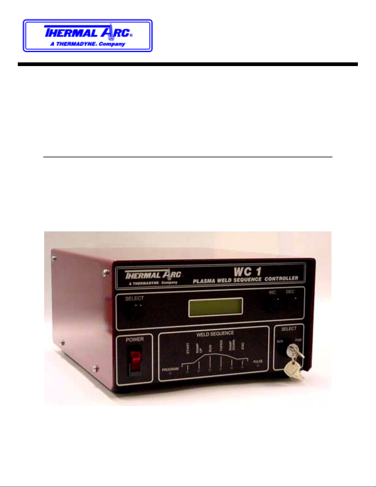
1.4 Control Display and Status Indicators
The controller has a 2-line 16-character Alpha Numeric LCD display which is used to program the
weld schedule data and to configure the control options. Three push button switches are used to
select the desired parameters and to increment or decrement the values. A Program/Run key lock
switch is provided to prevent unauthorized access to the WC 1 weld schedule and system
configuration. Eight Status LEDs are used to indicate the weld sequence events and selected
modes. The Program LED is illuminated when the WC 1 is in weld sequence mode. The Pulse
LED is illuminated when the Pulse Weld function is active. During a weld cycle the status LEDs will
be illuminated to indicate weld event sequence being executed. A RS-232-C serial port is provided
and allows the user to program all of the WC 1 schedules and features off-line.
2
Page 7
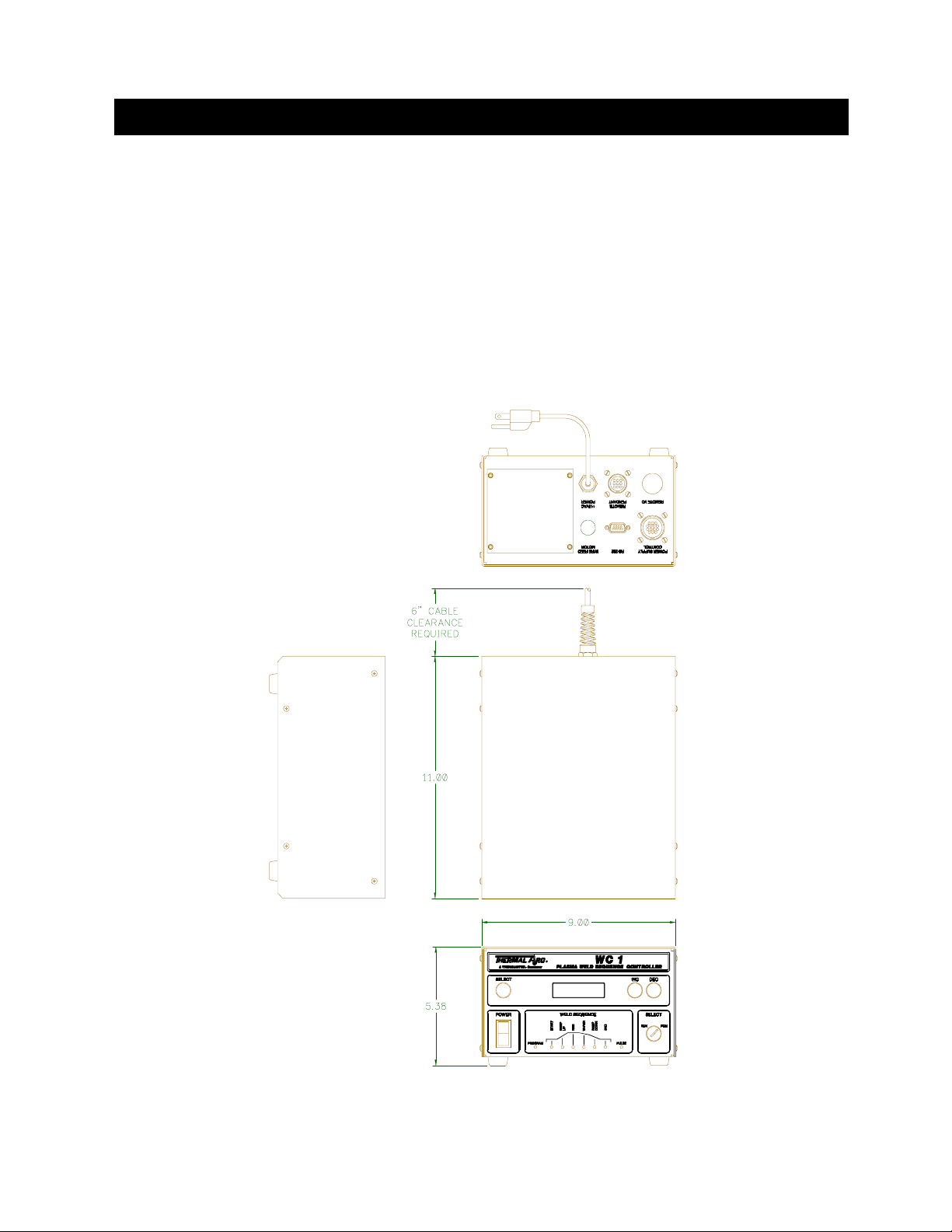
2.0 CONTROL IN ST ALLATION
2.1 Enclosure Installation
Install the Enclosure in a c onvenient location that al lows easy operator access to the front control
panel. Allow a minimum clearance of 6” (152mm) fr om the rear of the enc los ure to all o w ac c es s f o r
the external cable connectio ns. To permanently m ount the enclosure rem ove the four r ubber feet
and mount the enclosure using blind-hole fasteners located on the bottom of the enclosure. Connect
the Power cable to a suitable source of AC power. Connect the Po wer supply rem ote cable to the
“POWER SUPPLY CONTROL” rec eptac le. Connect the optional operator pendan t c ontr ol cab le to
the “REMOTE PENDANT” receptacle.
2.2 Standard Enclosure Dimens ions
3
Page 8

2.3 Remote Control Receptacle
The optional remote c ontrol receptacle provides a basic operational control interf ace to the WC 1
controller. The following is the pin-out and control function for the 9 pin receptacle.
PIN DESCRIPTION
1 +24 vdc @ 100 ma. Power Output
2 ESTOP – 24 VDC input
3 CYCLE START – 24 VDC input
4 INC – 24 VDC Input. Increase the current during the weld cycle
5 DEC – 24 VDC Input. Decreases the current during the weld cycle
6 CYCLE ON - 24 VDC Active low sinking (Pull-Down) output
7 CYCLE COMPLETE – 24 VDC Active Low sinking (Pull-Down) output
8 EARTH GROUND
9 READY – 24 vdc Active Low sinking (Pull-Down) output
Table 1 - WC 1 Remote Control Receptacle Pin-Out
4
Page 9

3.0 WELD SEQUENCE EVENTS
3.1 Weld Sequence Pa rameters
The WC 1 Plasma Weld Sequence Controller provides the following user defined parameters:
• START CURRENT – The value of current to be used during the start time event.
• START TI ME – The amount of time to hold the start current before beginning the Ramp Up
Event.
• RAMP UP TI ME – The time required to ramp from the start current to the run current.
• RUN CURRENT – The value of current to be used during the Run time of the weld cycle.
• WELD TIME – The user defined spot weld time when enabled.
• % TAPER CURRENT - The % of Run current used as the end current level for the taper
time and the start of the Ramp Down Event.
• TAP E R TIME – The amount of time required for the Current Taper Event.
• RA MP DO W N TI ME – The amount of time required to ramp from the % Taper current
value to the End current value prior to the End Current Event.
• END CURRENT - The end cycle current level to be used during the End Cycle Time.
• END TIME – The amount of time required for the end weld event.
3.2 Pulse Weld Mode P arameters
If the Pulse mode is enabled the following parameters will be used to define the pulse conditions:
• PULSE ON TIME – Specifies the Pulse On time period when the Pulse mode is enabled.
• PULSE OFF TIME – Specifies the Pulse Off time period when the Pulse mode is enabled.
• % PULSE CURRENT – Specifies the percent of the Run current that will be used during
the Pulse Off time period.
3.3 Weld Cycle Events
The Weld cycle is initiated by asserting the Cycle Start Input. The controller will monitor the Arc
Active input and will assert the Active output when active. The controller will set the Thermal Arc
Power source to the value specified by the Start Current Parameter. After the Start time has expired
the Current output would be ramped to the Run current value over the Ramp Up time specified. At
the end of the Ramp Time the Run current value will be active. If the Pulse mode is enabled the
Pulse On time will be used to specify the time at Peak Current. The Pulse Off Time and Percent
Current will be used to define the background pulse condition. If the Spot Time is Disabled the
controller will continue to operate in the Run Event. When the Cycle Start is reset the controller will
begin the Taper Time and ramp the Run current to the level specified by the Percent Taper
parameter. If the Pulse mode is enabled the pulsing will start during the Ramp Up event and will
continue through the ramp down event. At the end of the ramp down time the controller will set the
End Current value and will hold this value for the time specified by the End Time parameter. The
5
Page 10

Cycle Complete will be asserted at the end of the weld cycle when the Arc Active Signal has been
cleared by the power source. The Cycle complete will remain set until the next Cycle start is
asserted. To disable any weld event set the associated time to zero.
3.4 Spot Weld Mode
If the Spot Time mode is enabled the Taper Event will be started at the end of the Spot Weld Time.
Then the normal end events will be executed. In this mode the Cycle Start must be active until the
end of the weld cycle. The Controller will not reset the weld event until the Cycle input has been
cleared. The Cycle complete will be asserted when the Arc Active Signal is cleared. The Cycle
Complete Output will be cleared when the Cycle start is cleared.
3.5 Arc Active Test
If the Arc Active input from the power source is not active within the user specified start time after
the cycle start has been asserted, the controller will clear the weld event and reset the Ready
Output. The Cycle Start input must be cycled off before the Ready Output can be asserted. If the
Cycle start input is cleared prior to the weld event the controller will terminate the arc and will not set
the Cycle Complete output.
6
Page 11

4.0 USER INTERFACE
4.1 Remote Control Interface Specification
The WC 1 Controller provides a remote control interface that allows the user to connect an external
PLC or robotic control to the WC 1. The interface provides remote schedule select, cycle start and
operational status indication. The WC 1 inputs are configured to operate from a 24 VDC power
source. The inputs can be configured for Pull-Up (Sourcing) or Pull Down (Sinking). A 24 VDC @
200MA isolated power supply (TB5) is provided to allow dry contact closures to activate the WC 1
inputs. All Relay Outputs are opto-isolated solid-state relays and will switch AC/DC loads up to 120
VAC at 1 amp.
4.2 Remote Pendant Interface
A 9 pin CPC circular connector is provided to allow the use of a manual operator control pendant.
The Optional Operator Pendant is designed to connect to this Operator Control connector and will
perform the following Control functions:
• ESTOP – Palm button provides emergency stop input to the weld control.
• CYCLE ON – Toggle switch to start and stop a weld cycle.
• INC CURRENT – Pushbutton switch used to increase the Run current during a weld cycle.
The control will provide user defined limits for current change.
• DEC CURRENT – Pushbutton switch used to Decrease the Run current during a weld
cycle. The control will provide user defined limits for current change.
• READY – Green LED Indicator.
• CYCLE ON – Red LED Indicator.
• CYCLE COMPLETE – Green LED Indicator.
4.3 Optional Operator Pendant
The Operator Control Pendant is a NEMA 1 rated clamshell enclosure with a 15 ft control cable and
Remote I/O plug. If the WC 1 controller is to be used in a robotic or PLC based application the
remote pendant option is disabled and the inputs must be reconfigured for the desired remote
PLC/Robotic control functions.
4.4 RS-232 Serial Port
All weld schedule programming can be performed off-line via a RS-232 serial port or using the
internal display and program buttons. The Internal display allows the user to program all of the WC 1
Plasma Weld sequence parameters and to configure the controller operational modes. It can also
be used to Save and Load internal weld schedules.
4.5 Automated User Interface
The WC 1 controller allows full remote control capabilities for use with PLC or robotic controllers.
The control provides a 24-vdc interface that allows the users to select weld schedules and to
start/Stop the welding sequence. The controller provides a simple hand shaking output that allows
7
Page 12

the Host controller to validate the weld sequence. Four relay outputs provide the following
information to the host controller:
• CR1 - Ready – This output is asserted when the Controller is operating normally. It will
reset when the controller is in ESTOP or an Internal/External fault has occurred.
• CR2 - Arc Active – This output is asserted after the arc is established. The signal is
generated from the Thermal Arc power source. The output is cleared if a loss of arc is
detected, internal Program fault, or the cycle start signal is reset.
• CR3 - Cycle Complete – This output is asserted when the programmed weld cycle has
been completed. If a fault or loss of arc has occurred during the cycle the Cycle complete
will not be set.
• CR4 - Cycle Active – This output is active during the complete weld cycle and will be
cleared at the end of all programmed events.
The interface also provides a ESTOP circuit and six 24 vdc inputs that provide the following control
functions:
• ESTOP – This input must be active. If the ESTOP is cleared the control performs an
emergency stop and halts the weld cycle and resets all outputs. When asserted the
controller performs a power up sequence.
• INP 1 – SCHED 0 – User definable spare input. Under remote schedule mode this input
can be used for weld schedule selection (Bit 0).
• INP 2 – SCHED 1 - User definable spare input. Under remote schedule mode this input
can be used for weld schedule selection (Bit 1).
• INP 3 – SCHED 2/ PARAMETER SELECT - User definable spare input. Under Remote
Schedule Mode this input can be used for weld schedule selection (Bit 2). Under Remote
Control Mode this input is used to select the parameter to Increase/Decrease. When
Cleared the Current is selected. When Asserted the Wire Feed speed parameter is
selected. This option is only active when the optional wire drive and when the Remote
control mode is enabled.
• INP 4 – SCHED 3/ INCREASE PARAMETER – User definable spare input. Under Remote
Schedule Mode this input can be used for weld schedule selection (Bit 3). Under Remote
Control Mode activating this input will increment the selected parameter as specified by
INP3.
• INP 5 – SCHED 4/ DECREASE PARAMETER - User definable spare input. Under
Remote Schedule Mode this input can be used for weld schedule selection (Bit 4). Under
Remote Control Mode asserting this input will decrease the selected parameter as
specified by INP3.
• INP 6 - CYCLE START – This Input, when asserted, will start a weld cycle and must be
active during the complete weld cycle. If the input is reset the cycle will be terminated. If
the Spot Weld mode is enabled, the weld cycle will be terminated by the user defined weld
time. The Cycle start input must be reset before the next weld cycle can be initiated.
To use the Remote control interface the user must connect the PLC or Robot I/O to the internal
terminal blocks provide on the Main controller PCB assembly. The Remote Control function must
be enabled via the RS-232 serial port terminal command. See Section 7 for additional information.
8
Page 13

4.6 Typical User Interface for Automated Operation
321
ULTIMA-150 ENCLOUSER WC 1 ENCLOSURE
LOGIC BD
TB1
1
2
3
4
D
5
6
7
8
9
1 0
1 1
1 2
1 3
1 4
1 5
1 6
1 7
1 8
1 9
2 0
2 1
2 2
2 3
2 4
TB7
"WELD REMOTE"
1
2
3
4
5
6
7
8
TB3
"I/O POWER"
5
4
3
2
1
DAC 1
DAC 2
ANL COM
W_ARC ACTIVE
W_READY
WCOM
WC-A
WC-B
I/O COM
I/O COM
ESTOP+
+24 I/O
+24 I/O
4
D
CONNECTION TO ULTIMA-150 FOR AUTOMATED APPLICATIONS
C
B
CR6
CYCLE ON
CR5
SCHED4
CR4
SCHED3
CR3
SCHED2
CR2
SCHED1
CR1
SCHED0
OUTPUT COMMON
CYCLE ACTIVE OUTPUT
CYCLE COMPLETE OUPUT
ARC ON OUTPUT
READY OUTPUT
CMR
SYSTEM ESTOP
WC 1 CONTROL PCB ASS'Y
TB5
"I/O"
12
IN COM
11
START
SCHED 4
10
SCHED 3
9
8
7
6
5
4
3
2
1
TB3
"I/O POWER"
5
4
3
2
1
SCHED 2
SCHED 1
SCHED 0
OUT COM
ACTIVE
COMPLETE
ARC ON
READY
I/O COM
I/O COM
ESTOP+
+24 I/O
+24 I/O
5 - 24 VDC INPUT
TYPICAL OUTPUT
TYPICAL INPUT
2.7K
115 VAC/DC
@ 1AMP N.O.
READY
CYCLE START
ACTIVE
COMPLETE
ARC ON
TYPICAL WELD CYCLE I/O TIMING
NOTES:
1. WHEN REMOTE SCHEDULE OPTION IS ENABLED CR1-CR5 SELECT THE WELD SCHEDULE BASED ON DECODE TABLE
2. WHEN REMOTE SCHEDULE OPTION IS DISABLE CR1-CR2 HAVE NO EFFECT AND CR3-CR5 CONTROL THE FOLLOWING FUNCTIONS:
CYCLE ON (CR6 = ON) CYCLE OFF (CR6=OFF)
CR3 - SELECT AMP/WIRE (OFF = AMP) CR3 - SELECT AMP/WIRE (OFF = AMP)
CR4 - DECREASE RUNAMP/WIRE CR4 - JOG WIRE IN REVERSE DIRECTION
CR5 - JOG WIRE IN FORWARD DIRECTIONCR5 - INCREASE RUN AMP/WIRE
SCHEDULE SELECT DECODE
SCHED CR1 CR2 CR3 CR4
1
0000
2
1000
3
0100
4
1100
0010
5
1010
6
0110
7
1110
8
0001
9
1001
10
0101
11
1101
12
0011
13
1011
14
0111
15
1111
16
00001
17
1000
18
0100
19
1100
20
0010
21
1010
22
0110
23
1110
24
0001
25
1001
26
0101
27
1101
28
0011
29
1011
30
0111
31
1111
32
CR5
0
0
0
0
0
0
0
0
0
0
0
0
0
0
0
0
1
1
1
1
1
1
1
1
1
1
1
1
1
1
1
A
C
B
A
PLC/ROBOTIC WELD CONTROL INTERFACE
1 2 34
9
Page 14

5.0 CONTROL SPECIFICA TION
5.1 Enclosure Specification
The Weld Sequence Controller consists of a Main CPU P.C. board, Display/Keypad P.C. Board and
a 2-line 16-character LCD display. All external user connections are made via seven P.C. Board
mounted screw terminal blocks. The controller is designed to allow the addition of a Capstan PWM
motor drive controller, which can be used to control the Capstan Cold Wire Feed system. The PWM
module is installed in the rear of the control enclosure. There will also be provisions made to install
the necessary Power supply components inside the enclosure. This consists of a transformer, and
power supply assembly and wiring harness. This allows easy installation of the wire drive controller
option. The sheet metal enclosure is a clamshell design and conforms to a NEMA 1 rating.
5.2 Control Cables and Connectors
The enclosure has a single 15 ft rigid mounted power source control cable to interface to the
Thermal Arc power source. A rigid mounted 6 ft 115 VAC molded cable is used to provide power to
the controller. Provisions are made to allow a rigid mounted Capstan™ drive motor cable and PWM
Motor drive control Heat sink assembly to be installed. This option allows the WC 1 to program and
control a Capstan™ cold wire feed drive. A 9-pin CPC Circular connector is provided to allow
interconnection of an optional operator control pendant. A RS-232-C Female DB-9 connector is
provided to allow off-line programming of the weld schedules.
5.3 Controls and Status Indicators
The following is a summary of the front panel controls and status indicators:
• POWER SWITCH – Illuminated rocker switch applies power to the controller.
• PROGRAM/RUN – Key Lock switch that enables the WC 1 program mode. When the
switch is in the program position the user has full access to the controller weld schedules
and configuration parameters. When set in the run position the operator can only change
the parameters enabled within a specified high/low limit.
• SELECT – This momentary pushbutton switch is used to select the WC 1 parameter to be
modified. Editing of the selected parameter is only allowed when the key switch is in the
program position.
• INC /DEC – These two momentary push button are used to increase or decrease the
selected parameter. Editing of the selected parameter is only allowed when the key switch
is in the program position.
• START LED – Indicates when the weld event is in the start sequence.
• RAMP UP LE D – Indicates when the weld event is in the Ramp Up sequence.
• RUN LED – Indicates when the weld event is in the Run sequence.
• TAPER LED – Indicates when the weld event is in the Taper sequence.
• RAMP DOWN LED – Indicates when the weld event is in the Ramp down sequence.
• END LED – Indicates when the weld event is in the End sequence.
10
Page 15

• PROGRAM LED - Indicates when the WC 1 weld schedule program is active.
• PULSE LED - Indicates when the pulse mode is active.
5.4 System Specifications
The following are the system specifications:
Plasma Weld Sequence Controller:
Dimensions: 5.0"H x 9.0"W x 11" L ( 102mm x 165mm x 280 mm)
Power Input: 110 - 240 vac 50/6 0 hz @ 0.2kw
Operating Temp: -10 ° F to +140° F (-23°C to +60°C)
Relay Outputs: 115 VAC/VDC 1 amps nor mally open cont act
Switch Inputs: 5 - 2 4 vdc @ 1.0 - 8.0 m a.
Analog Outputs: 10 vdc precision refere nce ou tput. 10 bit re solut ion (10 mv
resolution) Max imum outpu t current 10 ma . Out put is short circuit
protected.
Encoder Input: Pulse accumulator input 5.0 v dc T TL lev el w ith 4.7K pull-u p.
Maximum input fr equen cy 15 khz.
11
Page 16

6.0 OPERA TIONAL DISPLAY AND PROGRAMMING
6.1 Static Weld Display Scr eens
The WC 1 controller provides a 2-lin e 16-character dis play and four c ontrol switches that allow the
user to program the weld var iables and to select the various weld schedules. W hen not altering
parameters the display will indicate current s tatus of the controll er. The first line of the display will
show the product type message. The Second line will show the current set point value for the
analog outputs that are enabled. The values displa yed are the final values for each weld cycle
event. The values are not varied during the ramp or pulse ev ent but are set to the e nd or peak
values. The actual valu es displayed are the result of the control mode and op tions installed. The
following are the various Weld active Display scr eens that wil l be dis pl a yed, dur ing a weld cycle, on
the second line of the display.
DISPLAY MESSAGE DESCRIPTION
AMP=### This screen will be displayed for PAW and GTAW mode when the wire drive
option is not inst alled . ( Where: ## # is the curre nt set po int v alue)
AMP=### W FS=### This screen will be displayed for PAW and GTAW mode when the wire drive
option is install ed. ( Wher e: ### is The curre nt set po int v alue)
VOL=##.# WFS=###
This screen w il l b e d is play e d f or G MAW mode. (Where: ### is The current set
point value)
Table 1 - Static Screen Display Message
12
Page 17

6.2 Static Display Screen Error M essages
During the weld cycle the WC 1 controller performs diagnostic checks on the system and control
inputs. If an error occurs the WC 1 will display the error message on the second line of the static
message screen. The following is a summary of the error messages:
DISPLAY ERROR MESSAGE DESCRIPTION
SCHED 1
READY!
PGM EVENT
ERROR!
No Errors. Normal st atic me ssage scre en di splay s act ive sch edule numbe r.
Program Event Error indicates the active weld schedule has an invalid event
enabled. Error is au tomat ically reset w hen Cy cle start is c leared.
POWER NOT
READY!
ARC ACTIVE FAIL! The Start param eter s are being ra mpe d t o th e ru n l ev el an d th e R a mp ti me delay
SCHEDULE
FAULT!
**SYSTEM
ESTOP**
Power supply not ready error indicates the Power supply ready input is not
asserted. This error will occur when the Cycle start is asserted and the Ready
input is not active. Error i s rese t when C yc le sta rt is clear ed.
is active.
Schedule Fault Error indicates the active weld schedule has an invalid
parameter. This error will occur when an out-of-range parameter is detected
during a weld cycl e. Error is au tomat ically r eset w hen Cy cle st art i s clear ed.
ESTOP message indicates that the WC 1 controller has been forced into a
Emergency stop conditi on by clearing the WC1 ESTOP input. When the ESTOP
mode is active all WC 1 outputs and weld events are cleared. The only recovery
is to assert the EST OP inp ut si gnal.
Table 2 - Displayed Error Messages
6.3 Modifying Weld Schedu le and System Parameters
The WC 1 Control provides two methods for programming a weld schedule. The first method is to
use a PC and the RS-232 serial port to program the schedules off line. Refer to Section 7.0 for
additional information on serial off-line programming. To create, modify or load a schedule set the
front panel key-lock switch to the “PROGRAM” position. The WC 1 will display the “WELD
PARAMETER" menu option. Select this menu by pressing the “SEL” button. To change the Control
configuration parameters press the “INC” or “DEC” button. The WC 1 will display the “
PARAMETER
” menu option. To select a specific menu option, press the “SEL” button. After
selecting a menu option the WC 1 will display the menu items and their current values on the
display. To move forward through the menu items press the “
previous menu item, press the “
DEC
” button. When moving through the menu items the WC 1 will
INC
” button. To move back to the
display the current value for each of the items selected. To change any selected item press the
“SELECT” button. A Blinking cursor will be displayed. To increase the displayed value, press the
INC
“
” button. To decrease the value, press the “
DEC
” button. To exit the edit routine press the
“SELECT” button. The Blinking cursor will be cleared from the display. Move to the next item by
pressing the “INC” or “DEC” buttons. To exit the schedule, edit routine turn the key-lock switch to the
“RUN” position. If a value has been modified, by pressing the “SELECT” button, the display will
show a “SAVING SCHEDULE” prompt indicating that the changes have been saved to the WC 1
nonvolatile Memory. The Display will then return to the normal Static display messages.
CONFIG
13
Page 18

6.4 Weld Schedule Parameter Menus
The WC 1 controller can support several different options. Depending on which options are
installed three different menus will be displayed. Each menu is specific to the available functions
and features that are installed. Placing the key-lock switch to the “RUN” position enables the edit
function. One of the following Program menus will be displayed.
6.5 PAW Weld Schedule Menu Screens
DISPLAY PARAMETER DESCRIPTION RANGE UNITS
START CURRENT
AMP =
START DELAY
TIME =
RAMP UP TIME
TIME =
RUN TIME CURRENT
AMP =
SPOT WELD TIME
TIME =
PERCENT TAPER
TAPER % =
TAPER DELAY TIME
TIME =
RAMP DOWN TIME
TIME =
END CURRENT
AMPS =
END DELAY TIME
TIME =
PULSE MODE
MODE =
PULSE ON TIME
TIME =
PULSE OFF TIME
TIME =
% BACKGROUND AMP
AMP % =
SELECT SCHEDULE
SCHED =
SAVE SCHEDULE
SCHED =
Weld cycle start current leve l. 1 - 500 Amps
The time period at t he Start curre nt lev el. 0 – 60.00 Sec.
The time that will be used to ramp the welding
current from the star t to th e r un va lue.
The current level that will be used during the run
time portion of the w eld cy cle .
The time period at the run current. If set the weld
sequence will automatically terminate at the end
of this time. If zero the user must clear the Cycle
start signal to ter minat e the w eld cycl e.
The percent of run current that will be reached at
the end of the taper event.
The time period to perform the current taper
event.
The time period used to r amp the curr ent fro m the
Taper % level to th e end current leve l.
The current level that will be used during the end
time period.
The time period at t he en d curren t lev el. 0 – 60.00 Sec.
Enable/Disable the pulse weld mode. If enabled
the pulse mode will be active from the start of the
ramp up event to the end of the ramp down
event.
The time period at the run current level when the
pulse mode is active.
The time period at the background current level
when the pulse mod e is a ctive.
The percent of the pea k current value that is used
for the background current leve l.
Select the user defined weld schedule and read
the schedule from weld memory into the active
weld schedule para meters .
Write the current active weld schedule to the
specified sched ule nu mber i n t he weld mem ory.
Table 3 - Weld Schedule Menu for PAW Welding Mode
0 – 60.00 Sec.
1- 500 Amps
0 – 650.00 Sec.
1 – 100 %
0 – 600.00 Sec.
0 – 60.00 Sec.
1 - 500 Amps
0 – 1 Yes/No
.001-60.000 Sec.
0.001-60.000 Sec.
1-100 %
1 – 32
1 - 32
14
Page 19

6.6 PAW With Cold Wire Feed Option Weld Schedule Menu Screens
DISPLAY PARAMETER DESCRIPTION RANGE UNITS
START CURRENT
AMP =
START WIRE SPEED
SPEED =
START DELAY
TIME =
RAMP UP TIME
TIME =
RUN TIME CURRENT
AMP =
RUN WIRE SPEED
SPEED =
SPOT WELD TIME
TIME =
PERCENT TAPER
TAPER % =
TAPER DELAY TIME
TIME =
RAMP DOWN TIME
TIME =
END CURRENT
AMPS =
END WIRE SPEED
SPEED =
END DELAY TIME
TIME =
REV WIRE DELAY
TIME =
PULSE MODE
MODE =
PULSE ON TIME
TIME =
PULSE OFF TIME
TIME =
JOG WIRE SPEED
SPEED =
% BACKGROUND AMP
AMP % =
SELECT SCHEDULE
SCHED =
SAVE SCHEDULE
SCHED =
Table 4 - Weld Schedule Menu for PAW with Cold Wire Feed option enabled
Weld cycle start current leve l. 1 - 500 Amps
The wire feed speed to be used during the start
time period. To disable set the speed to 0.
The time period at t he Start curre nt lev el. 0 – 60.00 Sec.
The time that will be used to ramp the welding
current from the star t to th e r un va lue.
The current level that will be used during the run
time portion of the w eld cy cle .
The wire feed speed to be used during the Run
time period. To disable set the speed to 0.
The time period at the run current. If set the weld
sequence will automatically terminate at the end
of this time. If zero the user must clear the Cycle
start signal to ter minat e the w eld cycl e.
The percent of run current that will be reached at
the end of the taper event.
The time period to perform the current taper
event.
The time period used to r amp the curr ent fro m the
Taper % level to th e end current leve l.
The current level that will be used during the end
time period.
The wire feed speed to be used during the end
time period. To di sable set t he sp eed to 0.
The time period at t he en d curren t lev el. 0 – 60.00 Sec.
The time period to reverse the wire feeder and
back the wire out of the arc. The Wire speed is
the end wire value.
Enable/Disable the pulse weld mode. If enabled
the pulse mode will be active from the start of the
ramp up event to the end of the ramp down
event.
The time period at the run current level when the
pulse mode is active.
The time period at the background current level
when the pulse mod e is a ctive.
The wire drive speed that is used while not
welding.
The percent of the pea k current value that is used
for the background current leve l.
Select the user defined weld schedule and read
the schedule from weld memory into the active
weld schedule para meters .
Write the current active weld schedule to the
specified sched ule nu mber i n t he weld mem ory.
0-1000 Ipm
0 – 60.00 Sec.
1- 500 Amps
0-1000 Ipm
0 – 650.00 Sec.
1 – 100 %
0 – 600.00 Sec.
0 – 60.00 Sec.
1 - 500 Amps
0-1000 Ipm
0 - 60.00 Sec.
0 – 1 Y es/No
.001-60.000 Sec.
0.001-60.000 Sec.
0 – 1000 Ipm
1-100 %
1 – 32
1 - 32
15
Page 20

6.7 GMAW Option Weld Schedule Menu Screens
DISPLAY PARAMETER DESCRIPTION RANGE UNITS
PREPURGE TIME
TIME =
START VOLTAGE
VOLTS =
START WIRE SPEED
SPEED =
START DELAY
TIME =
RAMP UP TIME
TIME =
RUN TIME VOLTAGE
AMP =
RUN WIRE SPEED
SPEED =
SPOT WELD TIME
TIME =
PERCENT TAPER
TAPER % =
TAPER DELAY TIME
TIME =
RAMP DOWN TIME
TIME =
END VOLTAGE
VOLTS =
END WIRE SPEED
SPEED =
END DELAY TIME
TIME =
REV WIRE DELAY
TIME =
BURN BACK TIME
TIME =
POST PURGE TIME
TIME =
JOG WIRE SPEED
SPEED =
SELECT SCHEDULE
SCHED =
SAVE SCHEDULE
SCHED =
Pre purge gas flow ti me per iod. 0 - 60.00 Sec.
Weld cycle start vo ltage level . 10.0- 50.0 Volts
The wire feed speed to be used during the start time
period.
The time period at t he Start lev el. 0 – 60.00 Sec.
The time that will be used to ramp the parameters
from the start to the ru n valu e.
The voltage level that will be used during the run time
portion of the weld cycle.
The wire feed speed to be used during the Run time
period.
The time period at the run level. If set the weld
sequence will auto ma tical ly ter minat e at th e end of thi s
time. If zero the user must clear the Cycle start signal
to terminate the weld cyc le.
The percent of run wire speed that will be reached at
the end of the taper event.
The time period to perform the tap er ev ent. 0 – 600.00 Sec.
The time period used to ramp from the Taper % level
to the end level.
The voltage level that will be used during the end time
period.
The wire feed speed to be used during the end time
period.
The time period at t he en d lev el. 0 – 60.00 Sec.
The time period to reverse the wire feeder and back
the wire out of the ar c. T he Wire spe ed is the end wire
value.
The time period, which will be used to hold the weld
contactor on after h altin g the w ire feed motor .
The Post Gas flow time perio d. .01-60.00 Sec.
The wire drive speed that is used w hile n ot w eldin g. 0 – 1000 Ipm
Select the user defined weld schedule and read the
schedule from weld memory into the active weld
schedule parameters.
Write the current active weld schedule to the specified
schedule number in the w eld memory .
Table 5
- Weld Schedule Menu for GMAW option enabled
0-1000 Ipm
0 – 60.00 Sec.
10.0- 50.0 Volts
0-1000 Ipm
0 – 650.00 Sec.
1 – 100 %
0 – 60.00 Sec.
10.0– 50.0 Volts
0-1000 Ipm
0 - 60.00 Sec.
.01 - 6.00 Sec.
1 – 32
1 - 32
16
Page 21

6.8 Setup Parameter Menus
The WC 1 controller can support several different options. The setup Parameter menu allows the
user to configure various setup control parameters and options. Depending on which options are
enabled different Weld parameter menus will be displayed. The user can also specify the current
range for a power supply and enable remote I/O weld schedule selections.
6.9 Setup Parameter Menu Screens
DISPLAY PARAMETER DESCRIPTION RANGE UNITS
REMOTE SCHEDULE
SELECT =
GTAW CONTROL
MODE =
GMAW CONTROL
MODE =
MAX CURRENT
AMP =
MIN CURRENT
AMP =
Enable remote weld schedule option. When “ON” the
user supplied I/O SC HED 0 - 4 inp uts (T B5-6- TB5-1 0) will
specify the desired weld schedule. Refer to Section 4.5
for additional infor matio n
Enables the GTAW process mode and weld parameter
menus
Enables the WC 1 control for the GMAW (MIG/MAG)
process mode and weld paramet er menu
The Maximum current level that the power source can
provide. This value is used to scale the WC 1 analog
output.
The Minimum current level that the power source can
provide. This value is used to scale the WC 1 analog
output.
Table 6- Setup Parameter menu functions
ON/OFF
ON/OFF
ON/OFF
1- 500 Amps
1- 500 Amps
17
Page 22

7.0 WC 1 OFF-LI NE RS-232 TER MINAL PR O T OCOL
7.1 General Description
The RS-232 Terminal mode can be use d to off -line program the user c onfigurable par ameter s and
operating modes. The pr otoc ol is a s imple ASCII command s tr ing that allows the user to upload or
download the various data. T he user can use any term inal program to perform the programming
function. All program command functions are case sensitive . The serial port is configured f or the
following data format:
• Baud Rate: 19.2K, Full Duplex
• Word Length: 8 Data Bits, One Stop and no parity
• Hand Shaking: None
7.2 Terminal Protocol
The protocol consists of a command string and optional data bytes. The command string is an
alpha character and an option number followed by a "=" or "?", followed by optional data and
terminated with an ASCII "cr" (0dh). The "=" will indicate that data is being sent to the selected
parameter by the host contro ller. T he "?" will ind icate a req uest f or data f rom the W C 1 to the host
controller. If the host is sending data to the WC 1 the data will be placed after the "=" character and
will be an ASCII string terminated with an ASCII "cr" (0dh). The following is an example of reading a
parameter value from the WC 1:
From Host type: V1? (cr)
Response from WC 1: ##
Where: ## is the current value for the parameter and (cr) is the
enter key
The following is an example of how to modify a value in the WC 1 using the terminal commands:
From Host type: V1=#### (cr)
Where: ## is the new value for the param eter and (cr) is the enter
key
18
Page 23

7.3 Terminal Commands
The following is a summary of the Terminal Commands supported by the WC 1:
COMMAND PARAMETER DESCRIPTION RANGE UNITS
V1 Prepurge time 0-650.00 .01Sec.
V2 Arc start current 0-500 Amps
V3 Arc Start Wire feed speed 0-650 Ipm
V4 Arc Start delay time 0-650.00 .01 Sec.
V5 Ramp up Delay time 0-650.00 .01 Sec
V6 Run time current (Pulse Peak curre nt) 0-650.00 Amps
V7 Run Time wire feed spee d 0-650 Ipm
V8 Spot Weld Time (If Time=0 then M anual contr ol) 0-650.00 .01 Sec.
V9 Percent Taper current 0-100 %
V10 Taper current delay time 0-650.00 .01 Sec.
V11 Ramp down delay tim e 0-650.00 .01 Sec.
V12 End current value 0-500 Amps
V13 End wire feed speed 0-650 Ipm
V14 End delay time 0-650.00 .01 Sec.
V15 Reverse wire speed tim e delay 0-650.00 Sec.
V16 Wire burn back delay time 0-650.00 .01 Sec.
V17 Post gas flow time d elay 0-650.00 .01 Sec.
V18 Pulse current on time .001 – 65.000 .001 Sec.
V19 Pulse current off time .001 – 65.000 .001 Sec.
V20 Percent back ground current 0-100 %
V21 Jog wire feed speed 0-650 Ipm
Table 7 - Weld Process and Command Table
19
Page 24

COMMAND PARAMETER DESCRIPTION RANGE
M1 Read Remote Inputs
BIT 0 – Schedule Bit 0 inpu t TB 5-6
BIT 1 – Schedule Bit 1 inpu t TB 5-7
BIT 2 – Schedule Bit 2 inpu t TB 5-8
BIT 3 – Schedule Bit 3 inpu t TB 5-9
BIT 4 – Schedule Bit 4 inpu t TB 5-10
BIT 5 – Power Supply Rea dy Inp ut TB7-5
BIT 6 – Arc Active Inp ut TB7- 4
BIT 7 – Cycle Start Input T B5-1 1
M2 Read/Write Remote Relay Output s CR 1-CR 6
BIT 0 – CR1 Weld Contact or Output T B7-7 & TB7-8
BIT 1 – CR2 Control Rea dy Outpu t T B5-1
BIT 2 – CR3 Arc Active O utput TB5-2
BIT 3 – CR4 Weld Cycle C omple te Ou tput T B5-3
BIT 4 – CR5 Weld Cycle A ctiv e Output T B5-4
BIT 5 – CR6 Enable Wire Driv e Outp ut TB4-4
M3 Read/Write System Configuration Param eters
BIT 0 – Enable Remote S chedu le Sel ect Fu nctio n
BIT 1 – Enable Wire Feed co ntrol f unction s
BIT 2 – Enable GMAW weld mode functions
BIT 3 – Enable GTA W weld mod e fun ction s
M4 Terminal Baud Rate control
0 = 76.8K Baud
1 = 38.4K Baud
2 = 19.2K Baud (Default)
3 = 9600 Baud
4 = 4800 Baud
5 = 2400 Baud
6 = 1200 Baud
M5 Weld Control Error Code
0 - No Error
1 - Weld Sequence Program Fault
2 - Power Supply Not Ready Fau lt
3 - ARC fail during weld cycle
4 - Schedule Fault – Invalid Param eter Data
5 - ESTOP active
M6 Set to “M6=251” and power cycle the WC1 will Clear Memory and
reload factory defa ult par amete rs ( Versio n 1.23 and h igh er).
0-255
0-255
0-15
0-6
1-5
251
Table 8
- System Configuration and Mode command table
20
Page 25

COMMAND PARAMETER DESCRIPTION RANGE
W1 Weld Schedule Mode Flag:
0-255
Bit 0 – Enable Pulse Weld Mode
Bit 1..7 – Not defined
W2 Active Weld Schedule number 1-32
W3 Active Weld Event number
0-11
0 - Cycle Off
1 - Cycle Start
2 - Pre Purge
3 - Start Time
4 - Ramp Up Time
5 - Run Time (Spot Weld Time if enab led)
6 - Taper Current time
7 - Ramp Down Time
8 - End Time
9 - Wire Reverse Time
10 - Burn Back Time
11 - Post Purge Time
W4 Write current schedule to s pecif ied w eld sch edule numb er 1-32
W5 Read specified weld schedu le fro m mem ory to active sche dule 1-32
Table 9 - Weld Mode Command Table
COMMAND PARAMETER DESCRIPTION RANGE
A1 Minimum Power supply current output (A1 = AMP
) used for DAC 1
min
0-255
scaling.
A2 Maximum Power supply current (A2=AMP
Where: (DAC 1 Gain = [4 000/( AM P
A3 Minimum Wire Feed s peed (A 3 = WIRE
max
– AMP
min
A4 Maximum Wire Feed Speed (A5=WIRE
Where: (DAC 2 Gain = [4000/ ( Wire
– WIRE
max
) used for DAC 1 scaling
max
)])
min
) used for DAC 2 scal ing 0-255
) used for DAC 2 scaling
max
)])
min
0-500
0-900
A5 Actual Setpoint value for DAC 1 0-500
A6 Actual Set point va lue for DAC2 0-900
Table 10
- Analog Scaling Command Table
21
Page 26

8.0 ENCLOSURE LA Y OUTS
8.1 WC 1 Control Enclosure - S tandard Layout P/N: C3A5003
FRONT VIEW
REAR VIEW
22
Page 27

8.2 WC 1 Control Enclosure - Caps tan Motor Drive Layout P/N: C3A5004
FRONT VIEW
REAR VIEW
23
Page 28

8.3 Operator Pendant P/N: C3A5006
DEC
COMPLETE
CYCLE
INC
ON
CYCLE
ON
!
CYCLE
!
OFF
READY
ESTOP
24
Page 29

9.0 ENCLOSURE P ARTS LISTS
9.1 WC 1 Control Enclosure - S tandard Layout P/N: C3A5003
ITEM QTY PART NO DESCRIPTION
1 1 C3A5003 WC 1 Control Enclosure
2 1 C3E5004 WC 1 Control Cover
3 1 C3E5005 WC 1 Control Front Overlay
4 1 C3E5010 WC 1 Control Cover Plate
5 1 C5A5003-WC Weld Control PCB Assembly
6 1 C5A5004-WC Universal Pendant PCB Assembly
7 1 S3A5031 2 x 16 LCD Display Assembly
8 1 S2M5087 2 x 16 LCD Display Lens
9 1 C3W5002 WC 1 Control Wire Harness
10 1 C3W5003 WC 1 Front Panel Wire Harness
11 1 C3W5004 WC 1 Power Cord
12 1 C3W5005 WC 1 Power Switch Wire Harness
13 4 X6S5050 Spacer, #2 x 7/16” Long Nylon HH Smith #9165
14 4 X6S5056 Spacer, #2-56 x ¾” Long Stainless Steel RAF #2061-256-SS
15 1 X3S5078 Switch, Power Rocker Cutler-Hammer #1600R11E
16 3 X3S5125 Switch, Black Pushbutton SPDT Idec #AB6M-M1-B
17 1 X3S5127 Switch, Keylock SPDT Idec #AS6M-2KT2PB
18 1 X3Z5027 Kit, Screwlock Std. Female Amp #205817-3
19 1 X3Z5006 Fitting, Black Pigtail Heyco #3240
20 4 X6Z5036 Bumper, Black HH Smith #2135
21 1 X6Z5089 Plug, Dome Hole Black 5/8" Heyco #2663
22 1 X6Z5069 Plug, Dome Hole Black 7/8" Heyco #2703
23 8 #2 Internal Lock Washer
24 4 #2-56 Hex Nut
25 4 #2-56 X 1/4" Long Pan Head Screw
26 18 #6-32 X 1/4" Long Pan Head Screw w/ Internal Lock Washer
27 8 #6-32 X 1/2" Long Pan Head Screw
28 8 #6 Internal Lock Washer
29 9 #6-32 Hex Nut
30 4 #10-32 X 1/2" Long Pan Head Screw
25
Page 30

26
Page 31

9.2 WC 1 Control Enclosure – Capstan Motor Drive Layout P/N: C3A5004
ITEM QTY PART NO DESCRIPTION
1 1 C3A5003 WC 1 Control Enclosure
2 1 C3E5004 WC 1 Control Cover
3 1 C3E5005 WC 1 Control Front Overlay
4 1 C5A5003-WC Weld Control PCB Assembly
5 1 C5A5004-WC Universal Pendant PCB Assembly
6 1 S3A5031 2 x 16 LCD Display Assembly
7 1 S2M5087 2 x 16 LCD Display Lens
8 1 C3W5002 WC 1 Control Wire Harness
9 1 C3W5003 WC 1 Front Panel Wire Harness
10 1 C3W5004 WC 1 Power Cord
11 1 C3W5005 WC 1 Power Switch Wire Harness
12 1 C3W5006 PWM Control Wire Harness
13 1 C3W5007 PWM AC Power Wire Harness
14 1 C3W5008 P WM DC Power Wire Harness
15 1 C3W5009 PWM Motor Drive Cable
16 1 C3W5010 PWM Toroidal Transformer
17 1 S2M5050 Microstep Heatsink
18 1 C5A5005 PWM Driver PCB Assembly
19 1 C5A5006-9CM PWM 9CM CPU PCB Assembly
20 1 C5A5007 PWM Power Supply PCB Assembly
21 7 X6S5023 Spacer, #6-32 x 1/2” Long SS M-F RAF #4534-632-SS-0
22 4 X6S5057 Spacer, #6-32 x 1/4” Long SS M-F RAF #4530-632-SS-0
23 1 X3C5026 Fuse, 8 amp 3ag Littlefuse #313008
24 4 X6S5050 Spacer, #2 x 7/16” Long Nylon HH Smith #9165
25 4 X6S5056 Spacer, #2-56 x ¾” Long Stainless Steel RAF #2061-256-SS
26 1 X3S5078 Switch, Power Rocker Cutler-Hammer #1600R11E
27 3 X3S5125 Switch, Black Pushbutton SPDT Idec #AB6M-M1-B
28 1 X3S5127 Switch, Keylock SPDT Idec #AS6M-2KT2PB
29 1 X3Z5027 Kit, Screwlock Std. Female Amp #205817-3
30 2 X3Z5006 Fitting, Black Pigtail Heyco #3240
31 4 X6Z5036 Bumper, Black HH Smith #2135
32 1 X6Z5069 Plug, Dome Hole Black 7/8" Heyco #2703
33 4 X5Z5007 Washer, Shoulder Thermalloy #7721-7PPS
34 3” Tape, Kapton 1” Wide
35 A/R Compound, Thermal Thermalloy #249
36 8 #2 Internal Lock Washer
37 4 #2-56 Hex Nut
38 4 #2-56 X 1/4" Long Pan Head Screw
39 4 #4-40 x 1/4” Long Pan Head Screw
40 18 #6-32 X 1/4" Long Pan Head Screw w/ Internal Lock Washer
41 8 #6-32 X 1/2" Long Pan Head Screw
42 8 #6 Internal Lock Washer
43 9 #6-32 Hex Nut
44 4 #6-32 X 3/8" Long Socket Cap Head Screw
45 4 #10-32 X 1/2" Long Pan Head Screw
46 1 #10-32 X 7/8" Long Pan Head Screw
47 1 #10 External Lock Washer
27
Page 32

282930
Page 33

Page 34

9.3 WC 1 Pendant Enclosure P/N: C3A5006
ITEM QTY PART NO DESCRIPTION
1 1 C3A5007 WC 1 Pendant Base
2 1 C3E5008 WC 1 Pendant Cover
3 2 X3S5125 Switch, Black Pushbutton SPDT Idec #AB6M-M1-B
4 1 X3S5126 Switch, Selector SPDT Idec #AS6M-2Y2P
5 1 X3S5128 Switch, Pushbutton Red SPDT Idec #AB6M-V1-R
6 2 X5D5052 LED, Green Imlec #LED-407G
7 1 X5D5053 LED, Red Imlec #LED-407R
8 2 X6A5014 Handle, Black 3” Center RAF #8047-440-A-24
9 1 X3P5793 Strip, Terminal 12 Circuit Molex #C1512-151
10 1 X3Z5006 Fitting, Black Pigtail Heyco #3240
11 25’ X3W5097 Cable, 8 Cond. 26awg Shielded Belden #1213A
12 1 X3P5142 Connector, Plug Housing 9 pin CPC Amp #206708-1
13 9 X3P0303 Socket, Crimp 20-24 Gauge Amp #66105-2
14 1 X3Z5060 Clamp, Cable CPC Amp #206966-1
15 4 X6Z5090 Bumper, Black Self-Adhesive HH Smith #2446-103
16 3 X5R0051 Resistor, 2.7K ohm 5% 1/2W #RL20S272G
17 2 #2-56 X 5/8" Long Pan Head Screw
18 2 #2 Internal Lock Washer
19 2 #2-56 Hex Nut
20 4 #4-40 X 1/4" Long Pan Head Screw w/ Internal Lock Washer
21 4 #6-32 X 1/4" Long Pan Head Screw w/ Internal Lock Washer
Page 35

31
 Loading...