

Page 1
REMOTE PENDANT OPERATING INSTRUCTIONS
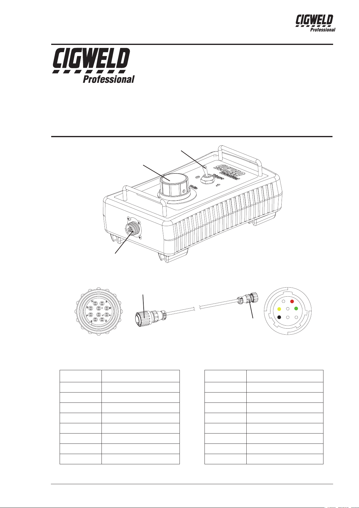
Trigger
Cigweld Pty Ltd
71 Gower Street
Preston, Victoria, Australia, 3072
Telephone: +61 3 9474 7400 • FAX: +61 3 9474 7391
Email: enquiries@cigweld.com.au
Website: www.cigweld.com.au
Knob
Manual 0-5263
Remote Pendant
Part Number: W4016900
Instruction Sheet
8 Pin Receptacle
10 Pin
8m 10P-8P Connecting Cable (supplied with the control pendant)
10 Pin
Pin Description
A Potentiometer Wiper
B, C Not Used
D Trigger Switch
E Potentiometer Maximum
Control Pendant
Art # A-12069
Art # A-12068
8 Pin
8 Pin
Pin Description
1 Not Used
2 Trigger Switch
3 Trigger Switch
4 Not Used
1
3
68
2
5
F Not Used
G Trigger Switch
H Potentiometer Minimum
I, J Not Used
© 2013 by Victor Technologies Industries
5 Potentiometer Maximum
6 Potentiometer Minimum
7 Not Used
8 Potentiometer Wiper
0-5263 1 May 15, 2013
Page 2
REMOTE PENDANT
WARNING
ELECTRIC SHOCK can kill.
Touching live electrical parts can cause fatal shocks or severe burns. The electrode and work
circuit is electrically live whenever the output is on. The input power circuit and machine internal
circuits are also live when power is on. In semiautomatic or automatic wire welding, the wire,
wire reel, drive roll housing, and all metal parts touching the welding wire are electrically live.
Incorrectly installed or improperly grounded equipment is a hazard.
1. Do not touch live electrical parts.
2. Wear dry, hole-free insulating gloves and body protection.
3. Insulate yourself from work and ground using dry insulating mats or covers.
4. Disconnect input power or stop engine before installing or servicing this equipment. Lock input power
disconnect switch open, or remove line fuses so power cannot be turned on accidentally.
5. Properly install and ground this equipment according to its Owner’s Manual and national, state, and local
codes.
6. Turn off all equipment when not in use. Disconnect power to equipment if it will be left unattended or out
of service.
7. Use fully insulated electrode holders. Never dip holder in water to cool it or lay it down on the ground or
the work surface. Do not touch holders connected to two welding machines at the same time or touch
other people with the holder or electrode.
8. Do not use worn, damaged, undersized, or poorly spliced cables.
9. Do not wrap cables around your body.
10. Ground the workpiece to a good electrical (earth) ground.
11. Do not touch electrode while in contact with the work (ground) circuit.
12. Use only well-maintained equipment. Repair or replace damaged parts at once.
13. In confined spaces or damp locations, do not use a welder with AC output unless it is equipped with a
voltage reducer. Use equipment with DC output.
14. Wear a safety harness to prevent falling if working above floor level.
15. Keep all panels and covers securely in place.
WARNING
ARC RAYS can burn eyes and skin; NOISE can damage hearing.
Arc rays from the welding process produce intense heat and strong ultraviolet rays that can burn
eyes and skin. Noise from some processes can damage hearing.
1. Use a Welding Helmet or Welding Faceshield tted with a proper shade of lter (see ANSI Z49.1 and AS
1674 listed in Safety Standards) to protect your face and eyes when welding or watching.
2. Wear approved safety glasses. Side shields recommended.
3. Use protective screens or barriers to protect others from flash and glare; warn others not to watch the
arc.
May 15, 2013 2 0-5263
Page 3

REMOTE PENDANT
4. Wear protective clothing made from durable, flame-resistant material (wool and leather) and foot protection.
5. Use approved ear plugs or ear muffs if noise level is high.
6. Never wear contact lenses while welding.
WARNING
FUMES AND GASES can be hazardous to your health.
Welding produces fumes and gases. Breathing these fumes and gases can be hazardous to your
health.
1. Keep your head out of the fumes. Do not breath the fumes.
2. If inside, ventilate the area and/or use exhaust at the arc to remove welding fumes and gases.
3. If ventilation is poor, use an approved air-supplied respirator.
4. Read the Material Safety Data Sheets (MSDSs) and the manufacturer’s instruction for metals, consumables, coatings, and cleaners.
5. Work in a confined space only if it is well ventilated, or while wearing an air-supplied respirator. Shielding gases used for welding can displace air causing injury or death. Be sure the breathing air is safe.
6. Do not weld in locations near degreasing, cleaning, or spraying operations. The heat and rays of the arc
can react with vapours to form highly toxic and irritating gases.
7. Do not weld on coated metals, such as galvanized, lead, or cadmium plated steel, unless the coating is
removed from the weld area, the area is well ventilated, and if necessary, while wearing an air-supplied
respirator. The coatings and any metals containing these elements can give off toxic fumes if welded.
WARNING
WELDING can cause fire or explosion.
Sparks and spatter fly off from the welding arc. The flying sparks and hot metal, weld spatter,
hot workpiece, and hot equipment can cause fires and burns. Accidental contact of electrode or
welding wire to metal objects can cause sparks, overheating, or fire.
1. Protect yourself and others from flying sparks and hot metal.
2. Do not weld where flying sparks can strike flammable material.
3. Remove all flammables within 35 ft (10.7 m) of the welding arc. If this is not possible, tightly cover them
with approved covers.
4. Be alert that welding sparks and hot materials from welding can easily go through small cracks and
openings to adjacent areas.
5. Watch for fire, and keep a fire extinguisher nearby.
6. Be aware that welding on a ceiling, floor, bulkhead, or partition can cause fire on the hidden side.
7. Do not weld on closed containers such as tanks or drums.
8. Connect work cable to the work as close to the welding area as practical to prevent welding current from
travelling long, possibly unknown paths and causing electric shock and fire hazards.
9. Do not use welder to thaw frozen pipes.
10. Remove stick electrode from holder or cut off welding wire at contact tip when not in use.
0-5263 3 May 15, 2013
Page 4

REMOTE PENDANT
!
WARNING
FLYING SPARKS AND HOT METAL can cause injury.
Chipping and grinding cause flying metal. As welds cool, they can throw off slag.
1. Wear approved face shield or safety goggles. Side shields recommended.
2. Wear proper body protection to protect skin.
WARNING
CYLINDERS can explode if damaged.
Shielding gas cylinders contain gas under high pressure. If damaged, a cylinder can explode.
Since gas cylinders are normally part of the welding process, be sure to treat them carefully.
1. Protect compressed gas cylinders from excessive heat, mechanical shocks, and arcs.
2. Install and secure cylinders in an upright position by chaining them to a stationary support or equipment
cylinder rack to prevent falling or tipping.
3. Keep cylinders away from any welding or other electrical circuits.
4. Never allow a welding electrode to touch any cylinder.
5. Use only correct shielding gas cylinders, regulators, hoses, and fittings designed for the specific
application; maintain them and associated parts in good condition.
6. Turn face away from valve outlet when opening cylinder valve.
7. Keep protective cap in place over valve except when cylinder is in use or connected for use.
8. Read and follow instructions on compressed gas cylinders, associated equipment, and CGA publication
P-1 listed in Safety Standards.
WARNING
MOVING PARTS can cause injury.
Moving parts, such as fans, rotors, and belts can cut fingers and hands and catch loose clothing.
1. Keep all doors, panels, covers, and guards closed and securely in place.
2. Stop engine before installing or connecting unit.
3. Have only qualified people remove guards or covers for maintenance and troubleshooting as necessary.
4. To prevent accidental starting during servicing, disconnect negative (-) battery cable from battery.
5. Keep hands, hair, loose clothing, and tools away from moving parts.
6. Reinstall panels or guards and close doors when servicing is finished and before starting engine.
This product, when used for welding or cutting, produces fumes or gases which contain chemicals know to the State of California to cause birth defects and, in some cases, cancer. (California
Health & Safety code Sec. 25249.5 et seq.)
Considerations About Welding And The Effects of Low Frequency Electric and Magnetic Fields
May 15, 2013 4 0-5263
WARNING
NOTE
Page 5

REMOTE PENDANT
The following is a quotation from the General Conclusions Section of the U.S. Congress, Office of Technology
Assessment, Biological Effects of Power Frequency Electric & Magnetic Fields - Background Paper, OTA-BP-
E-63 (Washington, DC: U.S. Government Printing Office, May 1989): “...there is now a very large volume of
scientific findings based on experiments at the cellular level and from studies with animals and people which
clearly establish that low frequency magnetic fields and interact with, and produce changes in, biological systems. While most of this work is of very high quality, the results are complex. Current scientific understanding
does not yet allow us to interpret the evidence in a single coherent framework. Even more frustrating, it does
not yet allow us to draw definite conclusions about questions of possible risk or to offer clear science-based
advice on strategies to minimize or avoid potential risks.”
To reduce magnetic fields in the workplace, use the following procedures.
1. Keep cables close together by twisting or taping them.
2. Arrange cables to one side and away from the operator.
3. Do not coil or drape cable around the body.
4. Keep welding power source and cables as far away from body as practical.
ABOUT PACEMAKERS:
The above procedures are among those also normally recommended for pacemaker wearers.
Consult your doctor for complete information.
0-5263 5 May 15, 2013
Page 6

REMOTE PENDANT
Description of Process
Manual Metal Arc Welding - covered
electrodes (MMAW)
Gas Metal Arc Welding (GWAW)
(MIG) other than Aluminium and
Stainless Steel
Gas Metal Arc Welding (GMAW)
(MIG) Aluminium and Stainless Steel
Gas Tungsten Arc Welding (GTAW)
(TIG)
Flux-cored Arc Welding (FCAW) -with
or without shielding gas.
Air - Arc Gouging Less than or equal to 400 12
Plasma - Arc Cutting
Plasma - Arc Spraying
Plasma - Arc Welding
Submerged - Arc Welding
Resistance Welding
Recommended Protective Filters for Electric Welding
Approximate Range of
Welding Current in Amps
Less than or equal to 100 8
100 to 200 10
200 to 300 11
300 to 400 12
Greater than 400 13
Less than or equal to 150 10
150 to 250 11
250 to 300 12
300 to 400 13
Greater than 400 14
Less than or equal to 250 12
250 to 350 13
Less than or equal to 100 10
100 to 200 11
200 to 250 12
250 to 350 13
Greater than 350 14
Less than or equal to 300 11
300 to 400 12
400 to 500 13
Greater than 500 14
50 to 100 10
100 to 400 12
400 to 800 14
—
Less than or equal to 20 8
20 to 100 10
100 to 400 12
400 to 800 14
—
—
Minimum Shade Number of
Safety Spectacles or eye
Filter(s)
15
2(5)
shield
Refer to standard AS/NZS 1338.1:1992 for comprehensive information regarding the above table
May 15, 2013 6 0-5263
Page 7

REMOTE PENDANT
Description
The CIGWELD Remote Pendant consists of a trigger switch and volts control potentiometer. It is specially
designed to allow use of voltage sensing wirefeeders with a range of CIGWELD power sources.
The trigger enables and disables the Power Source welding output, and the potentiometer controls welding
voltage.
Refer to list below for compatible CIGWELD power sources.
Installation
Attach the 8-pin connector on one end of the 10p-8p cable to the 8-pin receptacle on the front of the remote
pendant. And attach the 10-pin connector to the 10-pin receptable on the front of the welding machine. To
complete the connection, align the keyway, insert the plug, and rotate the threaded collar fully clockwise.
Operation
Set the trigger switch to "1" position to start the machine output functions. The remote pendant potentiometer
controls the welding voltage up to the level set on the welding power source. Note that the maximum voltage
must be set on the power source by the operator prior to the remote pendant being connected. With the remote pendant connected, the power source will only display minimum preview Volts until the Knob is rotated
then it displays actual welding voltage when welding. Rotate the knob clockwise to increases the welding
voltage; turning anti-clockwise decreases the welding voltage. Reseting the tirgger to "0" position completely
extinguishes the arc and initiates the post-flow shielding gas timer (where fitted).
This remote pendant is fully compatible with the following CIGWELD power sources:
Transmig 350i Part No: W1005353 and W1005359
Transmig 450i Part No: W1005453
Transmig 550i Part No: W1005553
Note 1: Other Power Source may not be fully compatible with the remote pendant.
The remote pendant potentiometer controls the welding voltage up to the level set on the welding power source.
Note that the maximum voltage must be set on the power source by the operator prior to the remote pendant
being connected. Rotate the remote pendant potentiometer clockwise to increase the welding voltage; rotate
anti-clockwise to decrease the welding voltage. The Power Source will preview the welding volts.
Set the Power Source to 10 pin Remote mode by pressing the remote / local button so the Remote LED is on,
and by pressing the 10 pin / 19 pin button until the 10 pin LED is on. The remote control pendant potentiometer
can adjust between 0 - 100% of the Power Source output volts setting. As an example, if the output voltage
on the power source front panel is set to 35V, the remote control device will be able to adjust between 14V to
35V over its complete range of rotation. If higher welding voltage is required, set the Power Source to Local
mode, adjust the output voltage, then return the Power Source to Remote mode.
Set the trigger switch to the "1" position to turn on the Power Source welding power output. Set the trigger
switch to "0" to turn off the Power Source welding power output.
Note 2: On some Power Sources, the welding output voltage at no load may be higher than the welding output
voltage.
0-5263 7 May 15, 2013
Page 8

REMOTE PENDANT
TERMS OF WARRANTY – JANUARY 2013
1. The Trade Practices Act 1974 (Commonwealth) and similar State Territory legislation relating to the
supply of goods and services, protects consumers’ interests by ensuring that consumers are entitled
in certain situations to the benefit of various conditions, warranties, guarantees, rights and remedies
(including warranties as to merchantability and fitness for purpose) associated with the supply of
goods and services. A consumer should seek legal advice as to the nature and extent of these protected
interests. In some circumstances, the supplier of goods and services may legally stipulate that the said
conditions, warranties, guarantees, rights and remedies are limited or entirely excluded. The warranties
set out in Clause 2 shall be additional to any nonexcludable warranties to which the Customer may be
entitled pursuant to any statute.
2. Subject to Clause 3. CIGWELD gives the following warranties to the Customer:
Insofar as they are manufactured or imported by CIGWELD, goods will upon delivery be of merchantable
quality and reasonably fit for the purpose for which they are supplied by CIGWELD.
CIGWELD will repair or, at its option, replace those of the goods which, upon examination, are found by
CIGWELD to be defective in workmanship and/or materials.
CIGWELD reserves the right to request documented evidence of date of purchase.
3. The Warranty in Clause 2;
Is conditional upon:
The Customer notifying CIGWELD or our Accredited Distributor in writing of its claim within seven (7)
days of becoming aware of the basis thereof, and at its own expense returning the goods which are
the subject of the claim to CIGWELD or nominated Accredited Distributor/Accredited Service Provider.
The goods being used in accordance with the Manufacturer’s Operating Manuals, and under competent
supervision.
Does not apply to:
Obsolete goods sold at auction, second-hand goods and prototype goods.
Breakdown or malfunction caused by accident, misuse or normal wear and tear.
Repairs or replacement made other than by CIGWELD or Accredited Service Providers, unless by prior
arrangement with CIGWELD.
Replacement parts or accessories which may affect product safety or performance and which are not
manufactured, distributed or approved by CIGWELD.
4. CIGWELD declares that, to the extent permitted by law, it hereby limits its liability in respect of the supply of goods which are not of a kind ordinarily acquired for personal, domestic or household use or consumption to any one or more of the following (the choice of which shall be at the option of CIGWELD).
The replacement of the goods or the supply of equivalent goods.
The repair of goods.
The payment of cost of replacing the goods or acquiring equivalent goods.
The payment of the cost of having goods repaired.
5. Except as provided in Clauses 2 to 4 above, to the extent permitted by statute, CIGWELD hereby excludes all liability for any loss, damage, death or injury of any kind whatsoever occasioned to the
Customer in respect of the supply of goods including direct, indirect, consequential or incidental loss,
damage or injury of any kind.
May 15, 2013 8 0-5263
Page 9

REMOTE PENDANT
WARRANTY SCHEDULE – JANUARY 2013
These warranty periods relate to the warranty conditions in clause 2. All warranty periods are from date of
sale from the Accredited Distributor of the equipment. Notwithstanding the foregoing, in no event shall the
warranty period extend more than the time stated plus one year from the date CIGWELD delivered the product to the Accredited Distributor. Unless otherwise stated the warranty period includes parts and labour.
CIGWELD reserves the right to request documented evidence of date of purchase.
REMOTE PENDANT
WARRANTY PERIOD 3 Months
Please note that the information detailed in this statement supersedes any prior published data produced by
CIGWELD.
0-5263 9 May 15, 2013
Page 10

Australia Terms of Warranty – 2013
Effective 1st January 2012, all warranties against defects (also known as a manufacturer’s
warranty) supplied with goods or services must comply with the new Australian consumer law
regulations (2010).
This Warranty Statement should be read in conjunction with the Warranty Schedule contained in
the operating instructions of the product. This schedule contains the warranty period applicable
to the product
Any claim under this warranty must be made within the warranty period which commences
on the date of purchase of the product. To make a claim under the warranty, take the product
(with proof of purchase from a Cigweld Accredited Seller) to the store where you purchased the
product or contact Cigweld Customer Care 1300 654 674 for advice on your nearest Service
Provider.
All costs associated with lodging the warranty claim including the return of goods to Cigweld or
our Nominated Accredited Distributor/Accredited Service Provider are the responsibility of the
consumer.
This warranty is given.
Cigweld Pty Ltd
A.B.N. 56007226815
71 Gower Street, Preston
Victoria, Australia, 3072
Phone: 1300 654 674
Email: enquiries@cigweld.com.au
Website: www.cigweld.com.au
This warranty is provided in addition to other rights and remedies you have under law: Our
goods come with guarantees which cannot be excluded under the Australian Consumer Law.
You are entitled to replacement or refund for a major failure and to compensation for other
reasonably foreseeable loss or damage. You are also entitled to have the goods repaired or
replaced if the goods fail to be of acceptable quality and the failure does not amount to a major
failure.
Failures due to incorrect use are not covered by this warranty and consumers are reminded to
only use the product in accordance with the Operating Instruction supplied with the product.
Additional copies of Operating Instructions are available from Cigweld Customer Care 1300 654
674 or the Website.
Page 11

GLOBAL CUSTOMER SERVICE CONTACT INFORMATION
Cigweld, Australia
71 Gower Street
Preston, Victoria
Australia, 3072
Telephone: 61-3-9474-7400
Fax: 61-3-9474-7391
Email: enquiries@cigweld.com.au
Victor Technologies USA
2800 Airport Road
Denton, Tx 76207 USA
Telephone: (940) 566-2000
800-426-1888
Fax: 800-535-0557
Email: sales@thermalarc.com
Victor Technologies Canada
2070 Wyecroft Road
Oakville, Ontario
Canada, L6L5V6
Telephone: (905)-827-1111
Fax: 905-827-3648
Victor Technologies, China
No.100 Lao Hongjing Rd,
Minhang District
Shanghai 200235
China
Telephone: 86-21-64072626
Fax: 86-21-64483032
Victor Technologies Asia Sdn Bhd
Lot 151, Jalan Industri 3/5A
Rawang Integrated Industrial Park - Jln Batu Arang
48000 Rawang Selangor Darul Ehsan
West Malaysia
Telephone: 603+ 6092 2988
Fax : 603+ 6092 1085
Victor Technologies Italy
OCIM, S.r.L.
Via Benaco, 3
20098 S. Giuliano
Milan, Italy
Tel: (39) 02-98 80320
Fax: (39) 02-98 281773
Victor Technologies Europe
Europe Building
Chorley North Industrial Park
Chorley, Lancashire
England, PR6 7Bx
Telephone: 44-1257-261755
Fax: 44-1257-224800
PT. Victor Technologies Utama Indonesia
Jl. Angsana II Blok AE No. 28
Delta Silicon I, Cikarang - Sukaresmi
Bekasi, 17550
Indonesia
Tel: +62 21 8990 6095
Fax: +62 21 8990 6096 / 1867
http://www.victortechnologies.com
Victor Technologies International
2070 Wyecroft Road
Oakville, Ontario
Canada, L6L5V6
Telephone: (905)-827-9777
Fax: 905-827-9797
Page 12

Asia Pacific Regional Headquarters
71 Gower Street
Preston, Victoria, Australia, 3072
Telephone: +61 3 9474 7400
FAX:
Email: enquiries@cigweld.com.au
+61 3 9474 7391
www.cigweld.com.au
 Loading...