

Page 1

Torch Handles,
Cutting Attachments,
and Heating Nozzles
English
Français
Español
Safety and Operating
Instructions
Issue Date: May 14, 2008Revision: C Form No.: 0056-0138
Page 2

We appreciate your business!
Congratulations on your new Victor® product. We are proud to have you as our customer
and will strive to provide you with the best service and reliability in the industry. This
product is backed by our extensive warranty and worldwide service network. To
locate your nearest distributor or service agency, please contact a representative at
the address and phone number in your area listed on the inside back cover of this
manual, or visit us on the web at www.victorequip.com.
This Operating Manual has been designed to instruct you on the correct use and
operation of your Victor® product. Your satisfaction with this product and its safe
operation is our ultimate concern. Therefore, please take the time to read the entire
manual, especially the Safety Precautions. They will help you to avoid potential hazards
that may exist when working with this product.
you are in GooD coMpany!
The Brand of Choice for Contractors and Fabricators Worldwide.
Victor® is a Global Brand of gas equipment products for Thermadyne Industries, Inc.
We manufacture and supply to major welding and cutting industry sectors worldwide,
including: Manufacturing, Construction, Mining, Automotive, Aerospace, Engineering,
Rural and DIY/Hobbyist, Scrap, Demolitions and Shipyards.
We distinguish ourselves from our competition through market-leading, dependable
products that have stood the test of time. We pride ourselves on technical innovation,
competitive prices, excellent delivery, superior customer service and technical support,
together with excellence in sales and marketing expertise.
Above all, we are committed to develop technologically advanced products to achieve
a safer working environment within the welding industry.
Page 3

WARNING
Read and understand this entire manual and your employer’s safety practices
before installing, operating, or servicing the equipment. While the information
contained in this manual represents the Manufacturer’s judgment, the
Manufacturer assumes no liability for its use.
Torch Handles, Cutting Attachments, and Heating Nozzles
Safety and Operating Instructions
Part Number 0056-0138
Published by:
Thermadyne® Industries, Inc.
2800 Airport Rd.
Denton, TX. 76208
(940) 566-2000
www.victorequip.com
U.S. Customer Care: (800) 426-1888
International Customer Care: (905) 827-9777
Copyright © 2008 Thermadyne Industries, Inc. All rights reserved.
Reproduction of this work, in whole or in part, without written permission of the publisher is
prohibited.
The publisher does not assume and hereby disclaims any liability to any party for any
loss or damage caused by any error or omission in this Manual, whether such error
results from negligence, accident, or any other cause.
Publication Date: March 18, 2008
Record the following information for Warranty purposes:
Where Purchased: _______________________________________________
Purchase Date: _________________________________________________
Equipment Serial #: ______________________________________________
i
Page 4

Table of Contents
SECTION 1: INTRODUCTION ....................................................... 1-1
SECTION 2: GENERAL SAFETY INFORMATION ...........................2-2
2.01 Fire Prevention ..................................................2-2
2.02 Housekeeping .................................................... 2-3
2.03 Ventilation ........................................................2-3
2.04 Personal Protection ..........................................2-3
2.05 Compressed Gas Cylinders ...............................2-4
SECTION 3: TORCH HANDLES ..................................................... 3-5
3.01 Welding Preparation .......................................... 3-5
3.02 Welding Setup ...................................................3-7
3.03 Welding Operation ............................................. 3-8
3.04 Welding or Heating Completion ......................... 3-9
SECTION 4: CUTTING ATTACHMENT .........................................4-10
4.01 Cutting Preparation ......................................... 4-10
4.02 Cutting Completion .......................................... 5-13
SECTION 5: CHECK VALVES AND FLASH ARRESTORS ..............5-13
5.01 Reverse Flow Check Valves .............................5-13
5.02 Flashback Arrestors ......................................... 5-14
5.03 Leak Testing .................................................... 5-15
SECTION 6: WELDING NOZZLES ................................................6-16
SECTION 7: SPECIFICATIONS ....................................................7-17
SECTION 8: STATEMENT OF WARRANTY .................................. 8-22
ii
Page 5
SECTION 1:
INTRODUCTION
This booklet is a guide to the safe and efficient operation of apparatus
used in oxy-fuel applications. If the apparatus is not used in an oxyfuel application, the operator must still follow safety and operating
procedures that apply. Usage presents several potential hazards. Read
this booklet thoroughly and carefully before operating this equipment.
All operations should conform to applicable Federal, State, County, or
City regulations for installation, operation, ventilation, fire prevention,
and protection of personnel. ANSI Standard Z49.1, “Safety in Welding
and Cutting" contains detailed safety instructions. It is available from the
American Welding Society, P.O. Box 351040, Miami, FL 33135.
A system of notes, cautions, and warnings emphasize important safety
and operating information in this booklet:
NOTE
Conveys installation, operation, or maintenance information which
is important but not hazard-related.
CAUTION
Caution indicates a potentially hazardous situation which, if not
avoided, may result in injury.
WARNING
WARNING
avoided, could result in death or serious injury.
DO NOT
and understand all safety and operating instructions provided. For
your safety, practice the safety and operating procedures described
in this booklet every time you use the apparatus. Deviating from
these procedures may result in fire, explosion, property damage
and/or operator injury. If at any time the apparatus you are using
does not perform in its usual manner, or you have any difficulty in
the use of the apparatus, STOP using it immediately. DO NOT use
the apparatus until the problem has been corrected!
indicates a potentially hazardous situation which, if not
WARNING
attempt to use this apparatus until you thoroughly read
1-1
Page 6

WARNING
Service or repair of apparatus should be performed only by a
qualified repair technician capable of servicing gas apparatus in
strict accordance to applicable Part and Service bulletins for Victor
®
manufactured products. Improper service repair, or modification of
the product could result in damage to the product or injury to the
operator. Improper service repair, USE OF NON-GENUINE VICTOR
®
PARTS, or modification could result in damage to the product or
injury to the operator.
WARNING
This product contains chemicals, including lead, or otherwise
produces chemicals known to the State of California to cause cancer,
birth defects and other reproductive harm. Wash hands after
handling. (California Health & Safety Code § 25249.5 et seq.)
SECTION 2:
GENERAL SAFETY INFORMATION
Read and understand all safety and operating instructions provided before
using this apparatus. RETAIN THESE INSTRUCTIONS IN A READILY
AVAILABLE LOCATION FOR FUTURE REFERENCE.
2.01 FIRE PREVENTION
Welding and cutting operations use fire or combustion as a basic tool. The
process is very useful when properly controlled. However, it can be extremely
destructive if not performed correctly in the proper environment.
1. The work area must have a fireproof floor.
2. Work benches or tables used during welding or cutting operations
must have fireproof tops.
3. Use heat resistant shields or other approved material to protect
nearby walls or unprotected flooring from sparks and hot metal.
4. Keep an approved fire extinguisher of the proper size and type
in the work area. Inspect it regularly to ensure that it is in proper
working order. Know how to use the fire extinguisher.
2-2
Page 7
5. Move combustible materials away from the work site. If you can
not move them, protect them with fireproof covers.
WARNING
NEVER pe rform welding, heating, or cutting operations
on a container that has held toxic, combustible or flammable
liquids, or vapors. NEVER perform welding, heating, or cutting
operations in an area containing combustible vapors, flammable
liquids, or explosive dust.
2.02 HOUSEKEEPING
WARNING
NEVER allow oxygen to contact grease, oil, or other flammable
substances. Although oxygen by itself will not burn, these
substances become highly explosive. They can ignite and burn
violently in the presence of oxygen.
Keep ALL apparatus clean and free of grease, oil, and other flammable
substances.
2.03 VENTILATION
WARNING
Adequately ventilate welding, heating, and cutting work areas
to prevent accumulation of explosive or toxic concentrations
of gases. Certain combinations of metals, coatings, and gases
generate toxic fumes. Use respiratory protection equipment in these
circumstances. When welding/brazing, read and understand the
Material Safety Data Sheet for the welding/brazing alloy.
2.04 PERSONAL PROTECTION
Gas flames produce infrared radiation which may have a harmful effect on
the skin and especially on the eyes. Select goggles or a mask with tempered
lenses, shaded 4 or darker, to protect your eyes from injury and provide
good visibility of the work.
2-3
Page 8

Always wear protective gloves and flame-resistant clothing to protect skin and
clothing from sparks and slag. Keep collars, sleeves, and pockets buttoned. DO
NOT roll up sleeves or cuff pants.
When working in a non-welding or cutting environment, always wear
suitable eye protection or face shield. Practice the following safety and
operation precautions EVERY TIME you use pressure regulation equipment.
Deviation from the following safety and operation instructions can result in
fire, explosion, damage to equipment, or injury to the operator.
2.05 COMPRESSED GAS CYLINDERS
The Department of Transportation (DOT) approves the design and
manufacture of cylinders that contain gases used for welding or cutting
operations.
1. Place the cylinder (Figure 1) where you will use it. Keep the cylinder
in a vertical position. Secure it to a cart, wall, work bench, post, etc.
WARNING
Cylinders are highly pressurized. Handle with care. Serious
accidents can result from improper handling or misuse of
compressed gas cylinders DO NOT drop the cylinder, knock it
over, or expose it to excessive heat, flames or sparks. DO NOT
strike it against other cylinders. Contact your gas supplier or refer
to CGA P-1 “Safe Handling of Compressed Gases in Containers”
publication.
NOTE
CGA P-1 publication is available by writing the Compressed Gas
Association, 4221 Walney Road, 5th Floor, Chantilly.VA 201512923
2. Place the valve protection cap on the cylinder whenever moving
it, placing it in storage, or not using it. Never drag or roll cylinders
in any way. Use a suitable hand truck to move cylinders.
3. Store empty cylinders away from full cylinders. Mark them “EMPTY”
and close the cylinder valve.
4. NEVER use compressed gas cylinders without a pressure reducing
regulator attached to the cylinder valve.
5. Inspect the cylinder valve for oil, grease, and damaged parts.
2-4
Page 9
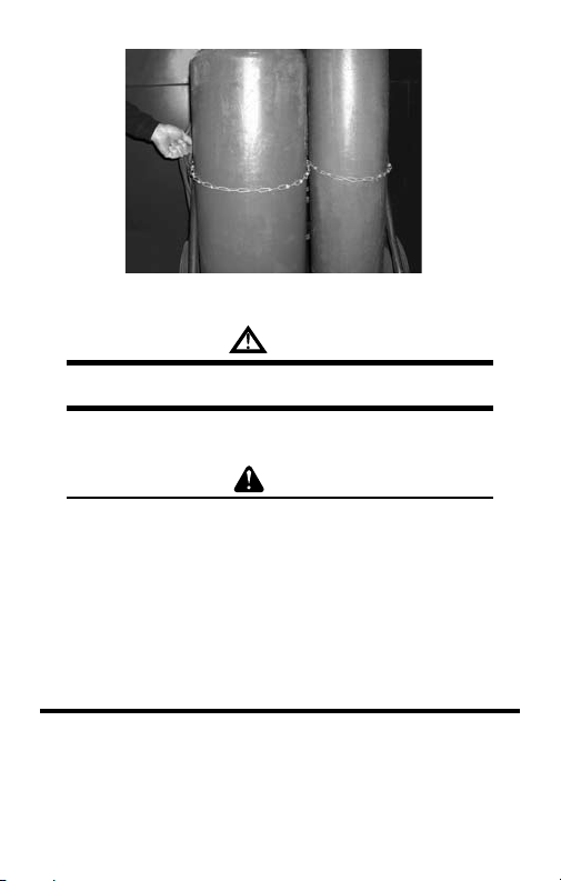
Figure 1: Gas Cylinders
WARNING
use the cylinder if you find oil, grease or damaged parts.
DO NOT
Inform your gas supplier of this condition immediately.
6. Momentarily open and close (called “cracking”) the cylinder valve
to dislodge any dust or dirt that may be present in the valve.
CAUTION
Open the cylinder valve slightly. If you open the valve too much,
the cylinder could tip over. When cracking the cylinder valve, DO
NOT stand directly in front of the cylinder valve. Always perform
cracking in a well-ventilated area. If an acetylene cylinder sprays
a mist when cracked, let it stand for 15 minutes. Then, try to
crack the cylinder valve again. If this problem persists, contact
your gas supplier.
SECTION 3:
TORCH HANDLES
3.01 WELDING PREPARATION
1. Be certain cylinder valves and regulator connections are completely
free of dirt, dust, oil, or grease.If oil, grease, or damage is detected
on the cylinder valves, DO NOT use the cylinder. Notify the cylinder
supplier immediately.If oil, grease, or damage is detected on the
3-5
Page 10
regulator, DO NOT use the regulator. Have the regulator cleaned
or repaired by a qualified repair technician.
2. Connect the oxygen hose to the oxygen regulator. Tighten the
connection firmly with a wrench.
3. Always open the cylinder valves slowly and carefully and check for
leaks on the regulator and cylinder valve connections.
4. Momentarily open and close the cylinder valve (commonly referred
to as “cracking”). This dislodges any loose contaminants that may
be present.
CAUTION
Open the cylinder valve only slightly. If the valve is opened too
much the cylinder could tip over. When “cracking” the cylinder
valve, DO NOT stand, nor have anyone stand directly in front of
the valve opening. Stand behind or to one side. Crack the cylinder
valve in a well-ventilated area only. If an acetylene cylinder sprays
a mist when it is cracked, let it set for 30 minutes. Then try to
crack the cylinder valve again. If the problem persists, contact
your gas supplier.
WARNING
Never stand, nor have anyone stand in front or behind a regulator
when opening the cylinder valve. Always stand so that the cylinder
is between you and the regulator.
5. Adjust the oxygen regulator to allow 3 - 5 PSIG to pass through the
hose. Allow oxygen to flow for 5 - 10 seconds to clear the hose of
dust, dirt, or preservatives. Shut off the oxygen flow.
6. Attach and clear the fuel hose in the same manner.
WARNING
Clear hoses in a well-ventilated area. The escaping gases create
conditions for fires and explosions. Keep hoses clear of any falling
metal, slag, or sparks. Never allow hoses to become coated with
oil, grease, or dirt. This could conceal damaged areas on the hoses.
Examine the hoses before attaching the torch handle or regulators.
If any cuts,burns, worn areas, cracks, or damaged fittings are found,
repair or replace the hose.
3-6
Page 11

7. Inspect the torch handle head, valves, and hose connections for oil,
grease, or damaged parts. Inspect the hose connections in the same
manner. DO NOT use them if oil, grease, or damage is detected.
8. Inspect the torch handle. The tapered seating surfaces in the head
must be in good condition. If dents or burned seats are present,
the seat must be resurfaced. If the torch handle is used with poor
seating surfaces, backfire may occur.
9. Using a 3/4" open-end wrench, check the flashback arrestors
to make sure they are tight. If loose, a flashback may have
occurred.
10. Attach the hose to the torch handle and tighten securely with a
wrench.
3.02 WELDING SETUP
1. Check the thickness of the metals to be welded. Prepare the metal
as described. Refer to the welding tip selection chart to determine
the tip size that is required and the regulator pressures for the
job.
2. Open the oxygen valve on the torch handle and adjust the oxygen
regulator to the required delivery range. Then close the torch handle
oxygen control valve to purge the oxygen hose.
3. Open the fuel valve on the torch handle and adjust the fuel regulator
to the required delivery range. Then close the torch handle fuel
control valve to purge the fuel hose.
WARNING
If the torch handle and hoses are already connected to the
regulators, the system MUST still be purged after every shutdown
in a well-ventilated area. Open the oxygen valve 1/2 turn. Allow the
gas to flow ten seconds for tips up to a size three and five seconds
for sizes 4 and larger for each 25 feet of hose in the system. Close
the oxygen valve and purge the fuel system in the same manner.
4. Wear the recommended protective goggles (shaded 5 or darker)
with tempered lenses to shield your eyes from the light. Wear
protective clothing as required.
3-7
Page 12
NOTE
The following instructions cover torch adjustment procedures for
acetylene only. Contact your gas supplier for instructions on the
use of other fuel gases.
5. Hold the torch in one hand and the spark lighter in the other. Be
sure the spark lighter is away from the tip and not obstucting the
gas flow.
6. Open the torch fuel valve approximately 1/8 turn and ignite the
gas.
CAUTION
Point the flame away from people, equipment, and all flammable
materials.
7. Continue opening the fuel valve until the flame stops smoking.
8. Open the torch oxyen valve until a bright neutral flame is
established.
WARNING
If you experience a sustained backfire (a shrill hissing sound when
the flame is burning inside the nozzle), immediately turn off the
oxygen valve on the torch handle. Then, turn off the fuel valve.
Allow the torch and nozzle time to cool before attempting to reuse.
If backfire recurs, take the apparatus to a qualified repair technician
for repair before using the equipment again.
3.03 WELDING OPERATION
1. Clean the metal joints to be welded from all scale, rust, dirt, paint,
grease, and all foreign materials.
2. Some thicker metals may require additional preparation. Base
metals 1/8" or less do not require beveling.
3. Place the metal to be welded on a non-flammable work table and
determine where the tacking will be required.
4. Begin by tacking the ends of the two pieces of metal together before
welding. Longer pieces may need to be tacked every few inches
along the joint.
3-8
Page 13

5. Longer pieces may also require additional penetration gap, VICTOR®
recommends 1/16" - 1/8".
6. Hold the torch nozzle at an angle of approximately 45° to the
joint.
7. Move the torch nozzle over the starting edges of the joint. Rotate
the flame near the metal in a circular or semicircular motion until
the base metals run into a small puddle.
8. Dip the end of the filler rod in and out of the molten puddle, this
melts the rod and adds to the puddle.
9. Continue the dipping motion of the filler rod into the puddle. Then
move the torch back and forth across the joint.
10. Advance the torch nozzle at a rate of approximately 1/16" of the
filler rod as it is added to the puddle until the end of the joint is
achieved.
3.04 WELDING OR HEATING COMPLETION
1. Shut off the torch oxygen valve. Then, shut off the torch fuel valve.
Be careful not to shut off the fuel valve first; this may create a “pop”
type sound. When the “pop” happens it throws carbon soot back
into the torch and may in time partially clog gas passages and the
flashback arrestors.
2. Close both cylinder valves.
3. Open the torch handle oxygen valve. Release the pressure from
the system and then close the torch oxygen valve.
4. Turn the adjusting screw on the oxygen regulator counterclockwise
to release all spring pressure.
5. Open the torch handle fuel valve and release the pressure from the
system. Close the torch fuel valve.
6. Turn the adjusting screw on the fuel gas regulator counterclockwise
to release all spring pressure.
7. Check the inlet gauges after a few minutes to ensure the cylinder
valves are turned off completely and there is no pressure remaining
in the system.
3-9
Page 14
SECTION 4:
CUTTING ATTACHMENT
4.01 CUTTING PREPARATION
1. Inspect the cone end, coupling nut, and torch head for oil, grease, or
damaged parts. Also inspect the cone end for missing or damaged
O-rings.
WARNING
If you find oil, grease, or damage, DO NOT use the apparatus until
it has been cleaned or repaired by a qualified repair technician.
The two O-rings on the cone end must be in place and in good
condition. The absence of either of these O-rings allows pre-mixing
of oxygen and fuel gases. This can lead to a sustained backfire
within the torch handle and cutting attachment.
2. Inspect the cutting tip and cutting attachment head. All tapered
seating surfaces must be in good condition. Discard damaged
cutting tips. If you find dents, burns, or burned seats, resurface
the torch head. If you use the cutting attachment with poor seating
surfaces, a backfire or sustained backfire may occur.
WARNING
If the tapered seats on the cutting tip are damaged, DO NOT use
the tip. Poor seating surfaces may cause a backfire or sustained
backfire.
3. Inspect the preheat and cutting oxygen holes on the tip. Slag can
stick on or in these holes. If the holes are clogged or obstructed,
clean them out with the proper size tip cleaner.
4. Insert the tip into the cutting attachment head. Tighten the tip nut
securely with a wrench (15 - 20 lbs. torque).
5. Connect the cutting attachment to the torch handle and tighten
the coupling nut until it is hand tight. DO NOT use a wrench, as
damage to the O-rings may occur creating a faulty seal.
6. Refer to the Tip Flow Data Charts for correct cutting tip, regulator
pressures, and travel speed.
4-10
Page 15

7. Follow cylinder and regulator safety and operating procedures.
8. Open the oxygen valve on the torch handle completely.
9. Open the preheat oxygen control valve on the cutting attachment
and adjust the oxygen regulator to the desired delivery pressure.
This will purge the oxygen hose.
10. Close the preheat oxygen control valve.
11. Open the fuel valve on the torch handle and adjust the fuel regulator
delivery range. This will purge the fuel hose.
12. Close the fuel control valve on the torch handle.
13. Momentarily depress the cutting oxygen lever to purge the cutting
oxygen passage in the cutting attachment.
WARNING
If the torch handle and hoses are already connected to the
regulators, the system MUST still be purged after each shutdown.
Open the oxygen valve 1/2 turn. Allow the gas to flow ten seconds
for tips up to size 3, and five seconds for sizes 4 and larger for
each 25 feet of hose in the system. Close the oxygen valve and
purge the fuel system in the same manner.
NOTE
Always wear protective clothing and proper goggles to shield your
eyes from infrared light.
14. Open the fuel valve on the torch handle approximately 1/8 turn
and ignite the gas with a spark lighter. Be sure the spark lighter is
away from the tip and not obstructing the gas flow.
15. Continue to increase the fuel supply at the torch handle until the
flame stops smoking.
16. Slowly open the preheat oxygen control valve on the cutting
attachment until the preheat flame is established with a smooth
inner cone.
17. Depress the cutting oxygen lever. If necessary, readjust the preheat
flames slightly to a neutral flame by increasing the preheat oxygen
at the cutting attachment until the preheat flames are again neutral.
If the preheat flames are not the same size and the cutting oxygen
is not straight, turn off the torch and let it cool, then clean the tip.
4-11
Page 16

WARNING
Never open and light the fuel gas torch and oxygen at the same
time.
WARNING
If you experience a sustained backfire (flame disappears and/or a
shrill hissing sound is heard caused by the flame burning inside the
cutting attachment), immediately turn off the preheat oxygen control
valve on the cutting attachment. Then turn off the torch handle fuel
valve. Allow the cutting attachment to cool before attempting to
relight. If backfire recurs, have the apparatus checked by a qualified
repair technician before using the apparatus again.
NOTE
Inspect the areas where slag and sparks will fall. Serious fires
and explosions are caused by careless torch operations. Take all
possible precautions. Have fire extinguishers available. Remove or
protect flammable substances, including oxygen and fuel hoses,
before starting to work.
18. Hold the cutting attachment and torch handle comfortably in both
hands. Stabilize the torch and position the cutting tip preheat flames
approximately 1/4" from the base metal.
19. Direct the preheat flame to the spot where the cut is to begin.
Before the cutting action can start, preheat the starting point of
the metal to a bright cherry red kindling temperature. When the red
spot appears, depress the cutting oxygen lever slowly and fully.
20. When the cut starts, move the torch in the direction you wish to
cut.
NOTE
Moving too slowly allows the cut to fuse together. Moving too fast
will not preheat the metal and the cut will be lost.
21. Continue to fully depress the cutting oxygen lever until the cutting
oxygen stream is past the base metal for a good drop cut.
4-12
Page 17

4.02 CUTTING COMPLETION
1. Shut off the oxygen preheat valve. Then, close the torch fuel valve.
Be careful not to shut off the fuel valve first, this may create a “pop"
type sound. When the “pop” happens it throws carbon soot back
into the torch and may in time partially clog gas passages and the
flashback arrestors.
2. Close both cylinder control valves on the gas source supply.
3. Open the oxygen valve and depress the cutting oxygen lever.
Release the pressure from the system and then close the oxygen
preheat and the torch handle oxygen control valve.
4. Turn the adjusting screw on the oxygen regulator counterclockwise
to release all spring pressure.
5. Open the torch fuel control valve and release the pressure from
the system. Close the fuel valve.
6. Turn the adjusting screw on the fuel gas regulator counterclockwise
to release all spring pressure.
7. Check the inlet gauges after a few minutes to ensure the cylinder
valves are turned off completely and no pressure remains in the
system.
8. Remove slag left on the cut edge with a chipping hammer or brush.
Never remove slag from the cut edge with the torch head or cutting
tip.
SECTION 5:
CHECK VALVES AND FLASH ARRESTORS
5.01 REVERSE FLOW CHECK VALVES
The body “Y” has two control valves attached to it. The valve bodies are
marked to distinguish between the two valves. The body of one valve has
left-hand threads to accept the fuel gas hose. The other valve body has
right-hand threads to accept the oxygen hose. The control valves never
require lubricating. Occasionally, the packing nuts may require a slight
adjustment.
Most VICTOR® torch handles are equipped with patented built-in reverse
flow check valves to reduce the possibility of mixing gases in the hoses
and regulators.
5-13
Page 18
CAUTION
Check valves are mechanical devices that can leak when dirty
or if abused. Check valves should be tested at least every six
months, more often if hoses are frequently disconnected. Careless
usage, dirt or abuse can shorten the service life of check valves,
thus requiring more frequent testing. Follow the manufacturer’s
instructions for testing the check valves.
NOTE
Reverse flow check valves are not the same as flashback arrestors.
Check valves are designed to help prevent reverse flow of gas
upstream of the torch. Flashback arrestors are designed to prevent
mixed gases from igniting upstream of the flashback arrestors.
5.02 FLASHBACK ARRESTORS
NOTE
VICTOR® torch handle model numbers that contain the letters
“FC” are equipped with built-in flashback arrestors and check
valves (i.e. 315FC). Model numbers with a “C” only contain built-in
check valves (i.e. 315C). Earlier versions without an “F” or “C” in
the model number contained neither (i.e. 315). For all “C” model
torch handles and earlier versions, it is recommended that add-on
flashback arrestors be installed. Most add-on flashback arrestors
also contain built-in check valves.
Most VICTOR® torch handles are equipped with built-in flashback arrestors.
Flashback arrestors are designed to prevent mixed gases from igniting
upstream of the flashback arrestors.
CAUTION
It is not recommended to use accessory flashback arrestors on
VICTOR® FC torch handles since these devices are already built-in.
Excessive flow restrictions may occur.
The flashback arrestors contained in this torch are designed to prevent a
flashback flame from entering the hose and gas supply system. A very fine
“filter-like” sintered stainless steel flame barrier stops flashback flame.
For maximum service life of the flashback arrestor, completely purge
all lines and hoses before connecting to the torch. This removes loose
5-14
Page 19

material contained in the hose or regulator that could restrict flow through
the flashback arrestor.
Flow restriction and torch overheating results if dirt or “oily” LPG residuals
are allowed to flow into the flashback arrestor and cause clogging. Make
sure not to draw liquid.
Always store and use cylinders in the upright position.
5.03 LEAK TESTING
The system MUST be tested for leaks before lighting the torch. To leak test
the system perform the following steps.
1. Be sure that both the oxygen and fuel control valves on the torch
handle are closed.
2. With the oxygen cylinder valve open, adjust the oxygen regulator
to deliver 20 PSIG.
3. With the fuel cylinder valve open, adjust the fuel regulator to deliver
10 PSIG.
4. Close both the oxygen and fuel cylinder valves.
5. Turn the adjusting screws counterclockwise 1/2 turn.
6. Observe the gauges on both regulators for five minutes. If the gauge
readings do not change, then the system is leak tight. If there is
a leak, use an approved leak detection solution to locate it. If the
inlet gauge reading decreases, there is a leak at the cylinder valve
or inlet connection. Tighten the inlet connection after the pressure
has been released from the regulator. If the inlet connection still
leaks try another cylinder. If the same leak develops, take the
regulator to a qualified repair technician. Never tighten a cylinder
valve. If the cylinder valve is leaking, remove the regulator from the
cylinder, place the cylinder outdoors and notify your gas supplier
immediately. If the delivery gauge reading decreases, there is a
leak at the regulator outlet connection, within the hose, at the
torch inlet connection or at the control valves on the torch handle.
Tighten the regulator outlet connection and the torch handle inlet
connection after the pressure has been released from the system. If
the connections are still leaking, take the regulator or torch handle
to a qualified repair technician. If the hoses are leaking, replace
them. If the high pressure gauge drops and at the same time the
5-15
Page 20
delivery gauge rises, there is a leak in the regulator seat. Take the
regulator to a qualified repair technician for repair.
7. After leak testing the system, open the cylinder valves and
proceed.
WARNING
If a leak has been detected anywhere in the system, discontinue
use and have the system repaired. DO NOT use leaking equipment.
Do not attempt to repair a leaking system while the system is under
pressure. Perform all operations in a well-ventilated area to help
prevent the concentration of flammable or toxic fumes.
SECTION 6:
WELDING NOZZLES
1. Inspect the cone end, coupling nut, O-rings, and welding nozzle
for damage, oil or grease. Do not use if damage or contaminants
are present.
WARNING
There must always be two O-rings on the cone end. The absence or
damage of either of these O-rings allows premixing of the oxygen
and fuel gases. This can lead to a sustained backfire within the
torch handle.
2. Connect the welding nozzle to the torch handle. Tighten the coupling
nut HAND TIGHT only. Using a wrench could damage the O-rings
and create a faulty seal.
MULTI-FLAME HEATING NOZZLES (ROSEBUDS)
Multi-flame heating nozzles are set up exactly as the welding nozzle.
Follow the safety and operation procedures described above for the
welding nozzle.
CAUTION
Never starve or choke a welding nozzle or multi-flame heating
nozzle. This causes overheating of the nozzle and a backfire or
sustained backfire may result. Should a sustained backfire occur
(flame pops and disappears and/or a hissing sound is heard, the
flame is burning inside the nozzle), immediately turn off the oxygen
6-16
Page 21

valve on the torch handle. Then, turn off the fuel valve. Allow the
nozzle to cool before using it. If a backfire reoccurs, have the
apparatus checked by a qualified technician before using again.
SECTION 7:
SPECIFICATIONS
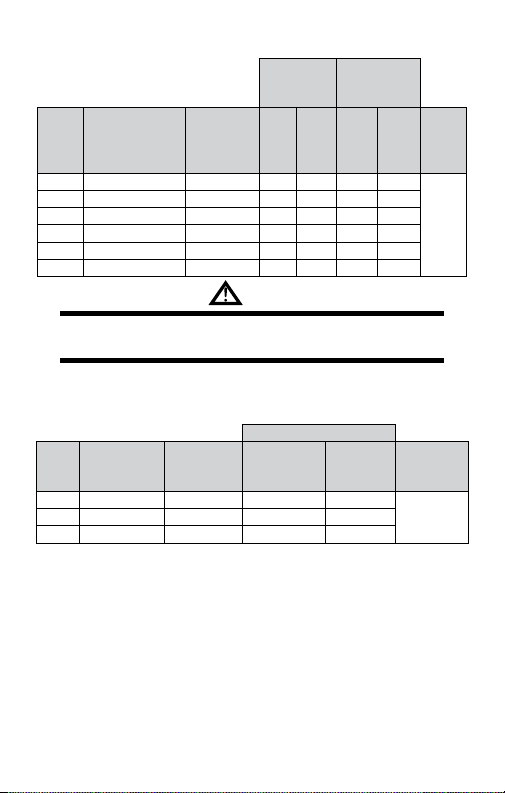
WELDING NOZZLE FLOW DATA
Oxygen
Pressure
Metal
Thickness
Up to 1/32" 000 75 (.022) 3 5 3 5 1 2
1/16" - 3/64" 00 70 (.028) 3 5 3 5 1 1/2 3
1/32" - 5/64" 0 65 (.035) 3 5 3 5 2 4
3/64" - 3/32" 1 60 (.040) 3 5 3 5 3 6
1/16" - 1/8" 2 56 (.046) 3 5 3 5 5 10
1/8" - 3/16" 3 53 (.060) 4 7 3 6 8 18
3/16" - 1/4" 4 49 (.073) 5 10 4 7 10 25
1/4" - 1/2" 5 43 (.089) 6 12 5 8 15 35
1/2" - 3/4" 6 36 (.106) 7 14 6 9 25 45
3/4" - 1 1/4" 7 30 (.128) 8 16 8 10 30 60
1 1/4" - 2" 8 29 (.136) 10 19 9 12 35 75
2 1/2" - 3" 10 27 (.144) 12 24 12 15 50 100
3 1/2" - 4" 12* 25 (.149) 18 28 12 15 80 160
Tip
Size
Drill Size
(PSIG)
Min Max Min Max Min Max
Acetylene
Pressure
(PSIG)
Acetylene
Consumption
(SCFH)
7-17
Page 22
MFA HEATING NOZZLES
Acetylene
Cubic Feet
per Hour
Acetylene
Tip
Pressure Range
Size
4 6 -10 8 - 12 6 20 7 22
6 8 -12 10 - 15 14 40 15 44
8 10 - 15 20 - 30 30 80 33 88
10 12 - 15 30 - 40 40 100 44 110
12* 12 - 15 50 - 60 60 150 66 165
15* 12 - 15 50 - 60 90 220 99 244
(PSIG)
At no time should the withdrawal rate of an individual acetylene cylinder exceed
1/7 of the cylinder contents per hour. If additional flow capacity is required, use an
acetylene manifold system of sufficient size to supply the necessary volume.
Oxygen
Pressure
Range
(PSIG)
Min Max Min Max
WARNING
Oxygen
Cubic Feet per
Hour
TYPE 55 NOZZLES
Not For Use With Acetylene
Oxygen
Tip
Pressure
Size
(PSIG)
10* 70 - 100 15 - 25 350 - 460 150 - 200
15* 90 - 120 20 - 35 600 - 800 250 - 350
20* 100 - 150 30 - 50 900 - 1150 400 - 500
*Use model HD310C torch and 3/8" hose.
Fuel Gas
Pressure
(PSIG)
Consumption (SCFH)
Oxygen
Fuel Gas BTU Hour
BTU
per
Hour
See
Note,
page
23
See Note,
page 23
7-18
Page 23

MFN HEATING NOZZLES
Propane Cubic
Propane
Tip
Pressure
Range
Size
(PSIG)
8 10-15 10-20 10 35 40 140
10 12-20 10-30 20 80 80 320
12* 15 - 25 30 - 125 30 160 120 640
15* 15 - 25 30 - 125 50 200 200 800
20* 20 - 30 40 - 135 75 250 300 1000
*Use model HD310C torch and 3/8" hose.
Oxygen
Pressure
Range
(PSIG)
Feet per Hour
Min Max Min Max
Oxygen Cubic
Feet per Hour
BTU per
Hour
See
Note,
page
23
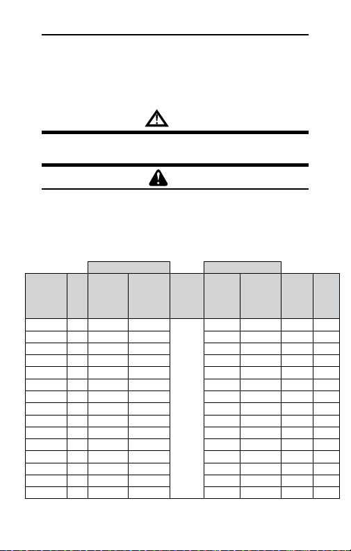
TYPES 1-101, 3-101 (OXY-ACETYLENE)
Cutting Oxygen Acetylene
-
Tip
Size
Pres
sure***
(PSIG)
Flow***
(SCFH)
Metal
Thickness
1/8" 000 20 - 25 20 - 25 3 - 5 3 - 5 6 - 11 20 - 30 .04
1/4" 00 20 - 25 30 - 35 3 - 5 3 - 5 6 - 11 20 - 28 .05
3/8" 0 25 - 30 55 - 60 3 - 5 3 - 5 6 - 11 18 - 26 .06
1/2" 0 30 - 35 60 - 65 3 - 6 3 - 5 9 - 16 16 - 22 .06
3/4" 1 30 - 35 80 - 85 4 - 7 3 - 5 8 - 13 15 - 20 .07
1" 2 35 - 40 140 - 160 4 - 8 3 - 6 10 - 18 13 - 18 .09
2" 3 40 - 45 210 - 240 5 - 10 4 - 8 14 -24 10 - 12 .11
3" 4 40 - 50 280 - 320 5 - 10 5 - 11 18 - 28 10 - 12 .12
4" 5 45 - 55 390 - 450 6 - 12 6 - 13 22 - 30 6 - 9 .15
6" 6** 45 - 55 500 - 600 6 - 15 8 - 14 25 - 35 4 - 7 .15
10" 7** 45 - 55 700 - 850 6 - 20 10 - 15 25 - 35 3 - 5 .34
12" 8** 45 - 55 900 - 1050 7 - 25 10 - 15 25 - 35 3 - 4 .41
* Applicable for three-hose machine cutting torches only. With a two-hose cuting torch,
preheat pressure is set by the cuttting oxygen.
** For best results use HC1200C series torches and 3/8" hose using a size 6 tip or
larger.
*** All pressures are measured at the regulator using 25' x 1/4" hose through tip size 5,
and 25' x 3/8" hose for tip size 6 and larger.
Pre-heat
Oxygen*
(PSIG)
Pres-
sure
(PSIG)
Flow
(SCFH)
Speed
(IPM)
Kerf
Width
7-19
Page 24
Approximate gross BTU contents per cubic foot:
Acetylene - 1470
•
Butane - 3374
•
Natural Gas - 1000
•
Propane - 2458
•
At no time should the withdrawal rate of an individual acetylene cylinder exceed
1/7 of the cylinder contents per hour. If additional flow capacity is required, use an
acetylene manifold system of sufficient size to supply the necessary volume.
NOTE
•
•
•
WARNING
Mapp - 2406
Methane - 1000
Propylene - 2371
Always make sure your equipment is rated for the size tip you have selected. A tip
with too much capacity for the equipment can starve or choke the tip. This causes
overheating of the head and a backfire may result. Use only genuine VICTOR®,
Cutskill®, or Firepower® cutting tips, welding nozzles and multi-flame nozzles to
ensure leak-free connections and balanced equipment.
CAUTION
TYPES 303M, GPM, GPN, GPP
Cutting Oxygen Pre-Heat Fuel Gas
Metal
Tip
Thickness
1/8" 000 20 - 25 12 - 14
1/4" 00 20 - 25 22 - 26 3 - 5 5 - 7 20 - 28 .05
3/8" 0 25 - 30 45 - 55 3 - 5 8 - 10 18 - 26 .06
1/2" 0 30 - 35 50 - 55 3 - 5 8 - 10 16 - 22 .06
3/4" 1 30 - 35 70 - 80 4 - 6 10 - 12 15 - 20 .08
1" 2 35 - 40 115 - 125 4 - 8 12 - 15 13 - 20 .09
1 1/2" 2 40 - 45 125 - 135 4 - 8 12 - 15 13 - 18 .09
2" 3 40 - 45 150 - 175 5 - 9 14 - 18 11 - 13 .10
2 1/2" 3 45 - 50 175 - 200 5 - 9 14 - 18 10 - 12 .10
3" 4 40 - 50 210 - 250 6 - 10 16 - 20 8 - 10 .12
4" 5 45 - 55 300 - 360 8 - 12 20 - 30 6 - 9 .14
5" 5 50 - 55 330 - 360 8 - 12 20 - 30 4 - 7 .14
6" 6 45 - 55 400 - 500 10 - 15 25 - 35 3 - 5 .17
8" 6 55 - 65 450 - 500 10 - 15 25 - 35 3 - 4 .18
12" 8** 60 - 70 750 - 850 10 - 14 25 - 120 3 - 4 .41
Size
Pressure
*** PSIG
Flow
SCFH
Pre-
Heat
Oxygen
PSIG
Note,
page
Pressure
PSIG
3 - 5 5 - 6 20 - 30 .04
See
23
Flow
SCFH
Speed
IPM
7-20
Kerf
Width
Page 25
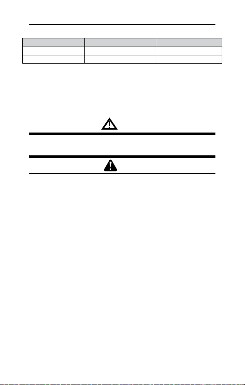
The above data applies to all torches with the following exceptions:
Torch Series Pre-heat Oxygen Pre-heat Fuel
MT 200 Series N/A 8 oz. - Up
MT 300 Series 10-50 PSIG 8 oz. - Up
* Applicable for 3-hose machine cutting torches only. With a two hose cutting torch,
preheat pressure is set by the cuttting oxygen.
** For best results use HC1200C and HC1100C series torches and 3/8" hose when using
a size 6 tip or larger.
*** All pressures are measured at the regulator using 25' x 3/8" hose for tip size 6 and
larger.
High gas withdrawal rates require use of a manifold system of sufficient size to
supply the necessary volume. High gas withdrawal rates may also require use
of a vaporizer.
NOTE:
WARNING
Always make sure your equipment is rated for the size tip you have selected. A tip
with too much capacity for the equipment can starve or choke the tip. This causes
overheating of the head and a backfire may result. Use only genuine VICTOR®,
Cutskill® or Firepower® cutting tips, welding nozzles and multi-flame nozzles to
ensure leak-free connections and balanced equipment.
CAUTION
7-21
Page 26

SECTION 8:
STATEMENT OF WARRANTY
LIMITED WARRANTY: THERMADYNE® warrants that its products will
be free of defects in workmanship or material. Should any failure to
conform to this warranty appear within the time period applicable to the
THERMADYNE products as stated below, THERMADYNE shall, upon
notification thereof and substantiation that the product has been stored,
installed, operated, and maintained in accordance with THERMADYNE’s
specifications, instructions, recommendations and recognized standard
industry practice, and not subject to misuse, repair, neglect, alteration,
or accident, correct such defects by suitable repair or replacement, at
THERMADYNE’s sole option, of any components or parts of the product
determined by THERMADYNE to be defective.
THIS WARRANTY IS EXCLUSIVE AND IS IN LIEU OF ALL OTHER
WARRANTIES, EXPRESS OR IMPLIED, INCLUDING ANY WARRANTY OF
MERCHANTABILITY OR FITNESS FOR A PARTICULAR PURPOSE.
LIMITATION OF LIABILITY: THERMADYNE shall not under any
circumstances be liable for special or consequential damages, such as,
but not limited to, damage or loss of purchased or replacement goods,
or claims of customers of distributor (hereinafter the “Purchaser") for
service interruption. The remedies of the Purchaser set forth herein are
exclusive and the liability of THERMADYNE with respect to any contract,
or anything done in connection therewith such as the performance
or breach thereof, or from the manufacture, sale, delivery, resale, or
use of any goods covered by or furnished by THERMADYNE whether
arising out of contract, negligence, strict tort, or under any warranty,
or otherwise, shall not, except as expressly provided herein, exceed
the price of the goods upon which such liability is based.
THIS WARRANTY BECOMES INVALID IF REPLACEMENT PARTS OR
ACCESSORIES ARE USED WHICH MAY IMPAIR THE SAFETY OR
PERFORMANCE OF ANY THERMADYNE PRODUCT.
THIS WARRANTY IS INVALID IF THE PRODUCT IS SOLD BY NONAUTHORIZED PERSONS.
This warranty is effective for the time stated in the Warranty Schedule
beginning on the date that the authorized distributor delivers the
products to the Purchaser.
8-22
Page 27

Warranty repairs or replacement claims under this limited warranty
must be submitted by an authorized THERMADYNE repair facility within
thirty (30) days of the repair. No transportation costs of any kind will
be paid under this warranty. Transportation charges to send products
to an authorized warranty repair facility shall be the responsibility of
the Purchaser. All returned goods shall be at the Purchaser’s risk
and expense. This warranty supersedes all previous THERMADYNE
warranties.
8-23
Page 28

Les Chalumeaux, Les
Attachements Coupeurs
et Buses de Chauffage
English
Français
Español
Guide d’installation et
d’utilisation
Date d’émission: 14 Mai 2008Révision: C Nº de document: 0056-0138
Page 29

VOTRE ACTIVITÉ NOUS INTÉRESSE!
Félicitations pour votre nouveau produit Victor®. Nous sommes fiers de vous avoir
comme client et nous tâcherons de vous fournir les meilleurs services et fiabilité
dans l’industrie. Ce produit est soutenu par une vaste garantie et un réseau mondial
de service. Pour localiser votre distributeur ou agence de service le plus proche,
veuillez communiquer avec un représentant à l’adresse ou au numéro de téléphone
correspondant à votre région, indiqué au verso de la couverture du manuel, ou visitez
notre site web www.victorequip.com.
Ce Manuel d’utilisation a été conçu pour vous permettre d’utiliser et de faire fonctionner
correctement votre produit Victor®. Votre satisfaction et le fonctionnement en toute
sécurité de votre produit sont nos principaux soucis. Par conséquent, veuillez prendre
le temps de lire tout le manuel, spécialement en ce qui concerne les Précautions de
Sécurité. Ceci vous aidera à éviter déventuels accidents qui pourraient survenir en
travaillant avec ce produit.
VOUS ÊTES EN BONNE COMPAGNIE!
La Marque de Choix pour les Entrepreneurs et les Fabricants
dans le Monde.
Victor® est une marque mondialement reconnue pour ses produits d’équipement de
gaz pour Thermadyne Industries, Inc. Nous fabriquons et fournissons dans le monde
entier aux secteurs industriels majeurs de soudage et coupage, incluant fabrication,
construction, exploitation minière, automobile, aérospatiale, ingénierie, rural et
bricolage/hobby, reyclage, démolition et construction navale.
Nous nous distinguons de notre concurrence grâce à nos produits en tête du marché,
fiables, ayant résisté à l’épreuve du temps. Nous sommes fiers de notre innovation
technique, nos prix compétitifs, notre excellente livraison, notre service clientèle et
notre support technique de qualité supérieure, ainsi que de l’excellence dans les
ventes et l’expertise en marketing.
Surtout, nous nous engageons à développer des produits utilisant des technologies
de pointe pour obtenir un environnement de travail plus sécurisé dans l’industrie
de la soudure.
Page 30

AVERTISSEMENT
Lisez et comprenez tout le Manuel et les pratiques de sécurité de l’utilisateur
avant l’installation, le fonctionnement ou l’entretien de l’équipement. Même si
les informations contenues dans ce Manuel représentent le meilleur jugement
du Fabricant, celui-ci n’assume aucune responsabilité pour son usage.
Les Chalumeaux, Les Attachements Coupeurs et Buses de Chauffage
Guide d’installation et d’utilisation
Numéro du Manuel d’Instructions pour 0056-0138
Publié par:
Thermadyne® Products Inc.
2800 Airport Road
Denton, TX 76208
(940) 566-2000
www.victorequip.com
Copyright © 2008 par Thermadyne Industries Inc.
® Tous droits réservés.
La reproduction, de tout ou partie de ce manuel, sans l’autorisation écrite de l’éditeur,
est interdite.
L’éditeur n’assume pas et dément toute responsabilité pour perte ou dommage causés
à une partie par erreur ou omission dans ce manuel, si une telle erreur résulte d’une
négligence, d’un accident, ou de toute autre cause.
Date de Parution: 19 Marche 2008
Complétez les informations suivantes à des fins de garantie:
Lieu D’achat: ___________________________________________________
Date D’achat: ___________________________________________________
Numéro de: ____________________________________________________
i
Page 31

Table of Contents
SECTION 1: INTRODUCTION ........................................................ 1-1
SECTION 2: INFORMATIONS GÉNÉRALES DE SÉCURITÉ ............. 2-2
2.01 Prévention D’incendie ........................................ 2-2
2.02 Entretien des Locaux ......................................... 2-3
2.03 Aération ............................................................. 2-3
2.04 Protection Personnelle ......................................2-4
2.05 Bouteilles de Gaz Comprimé .............................. 2-4
SECTION 3: LES CHALUMEAUX ...................................................3-6
3.01 Préparation de Soudure ..................................... 3-6
3.02 Installation de Soudure ......................................3-8
3.03 Opération de Soudure ......................................3-10
3.04 Accomplissement de Soudure et
de Chauffage ................................................... 3-10
SECTION 4: LES ATTACHEMENTS COUPEURS ...........................4-11
4.01 Préparation de Découpage............................... 4-11
4.02 Accomplissement de Découpage ..................... 4-15
SECTION 5: CLAPETS ANTI-RETOUR ET LES
5.01 Clapets Anti-Retour .........................................5-16
5.02 Les Intercepteurs de Retour de Flamme .......... 5-16
5.03 Recherche de Fuites ........................................5-17
SECTION 6: BUSE DE BRASAGE ................................................6-19
SECTION 7: CARACTÉRISTIQUES .............................................. 7-20
SECTION 8: GARANTIE .............................................................. 8-26
INTERCEPTEURS DE RETOUR DE FLAMME .........5-16
ii
Page 32

SECTION 1:
INTRODUCTION
Ce fascicule est un guide pour une utilisation sécurisée et efficace l’appareil
utilisés dans les applications à gaz oxygène carburant. Si l’appareil n’est
pas utilisé dans cet environnement, l’opérateur doit malgré tout appliquer
les procédures d’emploi qui s’appliquent à son application particulière.
Il y a plusieurs dangers potentiels à j’utilisation. Lisez complètement et
soigneusement ce fascicule avant de faire fonctionner cet équipement.
Toutes les opérations doivent être en conformité avec les règlements
fédéraux, d’état, de province ou ville applicables, pour l’installation, le
fonctionnement, la ventilation, la prévention d’incendie et la protection
des personnes. La norme ANSI Z49.1, “Sécurité en soudage et découpe”,
contient des instructions de sécurité détaillées. Elle peut s’obtenir auprès de
l’American Welding Society, P.O. Box 351040, Miami, FL 33135, U.S.A.
Un ensemble de conseils attirant l’attention et avertissant met en avant
des informations importantes sur la sécurité et le fonctionnement dans ce
document. Il s’agit de:
AVIS
Lavis donne de conseils d’installationou des informations
d’entretien qui sontimportants mais n’impliquent pas derisques.
MISE EN GARDE
La mention d’mise en garde indique une situation potentiellement
dangereuse qui, sans précautions, peut entraîner des dom.
AVERTISSEMENT
L’avertissement indique une situation potentiellement dan gereuse
qui, sans précautions, peut entraîner des dommages graves voire
mortels.
AVERTISSEMENT
N’essayez pas d’utiliser cet appareil sauf si vous êtes formé à sa
bonne utilisation ou bénéficiez d’une supervision qualifiée. Pour
votre sécurité, mettez en pratique les procédures de sécurité et
de mode opératoire décrites dans ce fascicule à chaque fois que
vous utilisez cet appareil. Si vous déviez de ces procédures, cela
peut entraîner incendie, explosion, dégâts matériels et/ou blessures
1-1
Page 33

corporelles. Si à un moment quelconque l’appareil que vous utilisez
ne se comporte pas de la façon habituelle, ou si vous éprouvez
des difficultés à le faire fonctionner, arrêtez immédiatement de
l’utiliser. Ne vous en servez plus jusqu’à ce que le problème ait
été corrigé!
AVERTISSEMENT
L’entretien ou la réparation de l’appareil ne doit être effectué que
par un technicien de support qualifié à même de s’occuper d’un
appareillage à gaz en stricte conformité avec les notes techniques
de pièces et réparation applicables pour les produits construits
par VICTOR®. Une mauvaise exécution de réparation, ou une
modification du produit, peut entraîner des dommages au produit
ou/blesser son opérateur. La réparation inexacte de service,
L’UTILISATION DES PIÈCES NON-VÉRITABLES DE VICTOR®, ou
la modification ont pu avoir comme conséquence les dommages
au produit ou les dommages à l’opérateur.
AVERTISSEMENT
Ce produit contient des produits chimiques, comme le plomb, ou
engendre des produits chimiques, reconnus par l’état de Californie
comme pouvant être à l’origine de cancer, de malformations fœtales
ou d’autres problèmes de reproduction. Il faut se laver les mains
après toute manipulation. (Code de Californie de la sécurité et
santé, paragraphe 25249.5 et suivants)
SECTION 2:
INFORMATIONS GÉNÉRALES DE SÉCURITÉ
Lisez et assimilez toutes les instructions de sécurité et de fonctionnement
fournies avant d’utiliser cet appareil. Gardez toutes ces instructions à un
emplacement facilement accessible comme référence ultérieure.
2.01 PRÉVENTION D’INCENDIE
Les opérations de soudage utilisent le feu ou la combustion comme outil de
base. Ce processus est très utile quand il est correctement contrôlé.
1. La zone doit comporter un sol ignifugé.
2-2
Page 34

2. Les établis ou tables utilisés pendant les opérations de
soudage doivent avoir un revêtement ignifuge.
3. Utilisez des écrans résistants à la chaleur ou en matériau approuvé
pour protéger les cloisons proches ou le sol vulnérable des
étincelles et du métal chaud.
4. Gardez un extincteur approuvé du bon type et de la bonne taille dans
la zone de travail. Inspectez-le régulièrement pour vous assurer
qu’il est en état de fonctionner. Apprenez à vous en servir.
5. Enlevez tous les matériaux combustibles de la zone de travail.
Si vous ne pouvez pas les enlever, protégez-les avec une couvre
ignifuge.
AVERTISSEMENT
N’effectuez JAMAIS d’opérations de soudage sur un récipient
qui a contenu des liquides ou vapeurs toxiques, combustibles
ou inflammables. N’effectuez JAMAIS d’opérations de soudage
dans une zone contenant des vapeurs combustibles, des liquides
inflammables ou des poussières explosives.
2.02 ENTRETIEN DES LOCAUX
AVERTISSEMENT
Ne laissez jamais l’oxygène en contact avec la graisse, l’huile ou
d’autres substances inflammables. Bien que l’oxygène ellemême
ne brûle pas, ces substances peuvent devenir extrêmement
explosives. Elles peuvent prendre feu et brûler violemment en
présence d’oxygène.
Gardez TOUS les appareils propres et exempts de graisse, huile ou autres
substances inflammables.
2.03 AÉRATION
AVERTISSEMENT
Ventilez les zones de soudage, chauffage et découpage de façon
adéquate pour éviter l’accumulation de gaz explosifs ou toxiques.
Certaines combinaisons de métaux, revêtements et gaz génèrent
des fumées toxiques: Utilisez un équipement de protection
2-3
Page 35

respiratoire dans ces circonstances. Si vous soudez ou brasez, lisez
et assimilez la fiche technique de sécurité de matériau relative à
l’alliage de soudage/brasage.
2.04 PROTECTION PERSONNELLE
Les flammes de gaz produisent une radiation infrarouge qui peut avoir un
effet néfaste sur la peau, et particulièrement sur les yeux. Choisissez des
lunettes ou un masque avec des verres trempés assombris au niveau 4 ou
plus sombre, pour protéger vos yeux des dommages et garder une bonne
visibilité sur le travail.
Portez en permanence des gants de protection et des vêtements ignifuges
pour la protection de la peau et des vêtements contre les étincelles et le
laitier. Gardez col, manches et poches boutonnés. Il ne faut pas remonter
vos manches ou les pantalons à revers.
Quand vous travaillez dans un environnement non dédié au soudage ou
découpage, portez toujours une protection des yeux appropriées ou un
masque facial.
AVERTISSEMENT
Mettez en pratique les procédures de sécurité et de mode opératoire
suivantes à chaque fois que vous utilisez cet appareil de régulation
de pression. Si vous déviez de ces procédures, cela peut entraîner
incendie, explosion, dégâts matériels et/ou blessures corporelles
pour l’opérateur. *
AVIS
Ce document CGA p. t peut être obtenu en écrivant à “Compressed
Gas Association”, 4221 Walney Roed, 5th Floor. Chantilly, VA
20151.2923, USA.
2.05 BOUTEILLES DE GAZ COMPRIMÉ
Le Département des Transports américain (DOT) approuve la conception
et la fabrication des bouteilles qui contiennent les gaz utilisés pour les
opérations de soudage ou de découpage.
1. Placez la bouteille (Le schéma 1) là où elle sera utilisée. Gardez-la
en position verticale. Fixez-la sur un chariot une cloison, un établi, etc.
2-4
Page 36

Le schéma 1: Cylindres de gaz
AVERTISSEMENT
Les bouteilles sont sous haute pression. Manipulez-les avec
précautions. Des accidents sérieux peuvent résulter d’une
mauvaise manutention ou d’un mauvais emploi des bouteilles
de gaz comprimé. NE faites PAS tomber la bouteille, ne la cognez
pas, ne l’exposez pas à une chaleur excessive, aux flammes ou
étincelles. NE la cognez PAS contre d’autres bouteilles. Contactez
votre fournisseur de gaz ou reportezvous à la publication CGA
P-1 “Manipulation sécurisée des gaz comprimés en conteneur”
pour plus d’informations sur l’utilisation et la manutention des
bouteilles.
2. Placez le bouchon de protection de vanne sur la bouteille à chaque
fois que vous la déplacez ou ne l’utilisez pas. Ne faites jamais
glisser ou rouler d’aucune manière les bouteilles. Utilisez un diable
approprié pour les déplacer.
3. Entreposez les bouteilles vides à l’écart des bouteilles pleines.
Marquez-les “VIDE” et refermez leur vanne.
4. N’utilisez JAMAIS des bouteilles de gaz comprimé sans un
régulateur de pression en série sur la vanne de bouteille.
5. Inspectez la vanne de bouteille pour y détecter de l’huile ou de la
graisse, ou dès pièces endommagées.
2-5
Page 37

AVERTISSEMENT
N’UTILISEZ PAS la bouteille si vous trouvez de l’huile, de la graisse
ou des pièces endommagées. Informez immédiatement votre
fournisseur de’ gaz de cet état.
6. Ouvrez et fermez momentanément la vanne de la bouteille,
délogeant ainsi d’éventu lIes poussières ou saletés. qui pourraient
être présentes dans la vanne.
MISE EN GARDE
Ouvrez la vanne de bouteille légèrement. Si vous l’ouvrez trop en grand,
la bouteille pourrait se renverser. Quand vous ouvrez/fermez rapidement
la vanne de bouteille, ne vous tenez pas directement devant. Opérez
toujours cette opération dans une zone bien ventilée. Si une bouteille
d’acétylène crache un brouillard, laissez reposer pendant 15 minutes.
Essayez de nouveau la vanne. Si le problème persiste, contactez votre
fournisseur de gaz.
SECTION 3:
LES CHALUMEAUX
3.01 PRÉPARATION DE SOUDURE
1. Assurez-vous que les robinets de la bouteille et les branchements
du détendeur sont dépourvus de poussières, saletés ou graisse.Si
vous détectez de l’huile, de la graisse ou des dommages sur les
robinets de la bouteille, ne l’utilisez PAS. Avisez le fournisseur de
bouteilles immédiatement.Si vous détectez de l’huile, de la graisse
ou des dommages sur le détendeur, ne l’utilisez PAS. Faites nettoyer
ou réparer le détendeur par un technicien de réparation qualifié.
2. Branchez le tuyau d’oxygène au détendeur d’oxygène. Serrez le
branchement solidement à l’aide d’une clé.
3. Ouvrez toujours les robinets de la bouteille très lentement et
avec précaution.Vérifiez toujours la présence de fuites sur les
branchements du détendeur et du robinet de la bouteille.
4. Ouvrez lentement et soigneusement le robinet de la bouteille
d’oxygène jusqu’à ce que la pression maximum apparaisse sur
3-6
Page 38

le manomètre haute pression. Ouvrez maintenant le robinet de la
bouteille entièrement afin de sceller sa garniture d’étanchéité.
MISE EN GARDE
Ouvrez le robinet de la bouteille d’acétylène environ trois quarts
de tour mais pas plus d’un tour et demi. Pour tous les autres gaz
combustibles, ouvrez la bouteille entièrement. Gardez la clé, si
une est nécessaire, sur le robinet de la bouteille afin de pouvoir
rapidement fermer le robinet en cas de présence d’une situation
d’urgence.
AVERTISSEMENT
Ne vous placez, ni ne laissez une personne se tenir debout
directement devant ou derrière un détendeur lors de l’ouverture
du robinet de la bouteille. Tenez-vous debout de façon à ce que le
robinet de la bouteille soit entre vous et le détendeur.
5. Ajustez le détendeur d’oxygène afin de permettre à 21 à 34 kPa de
circuler dans le tuyau. Laissez l’oxygène circuler 5 à 10 secondes
afin de retirer les poussières, saletés ou agents conservateurs du
tuyau. Fermez le débit d’oxygène.
6. Fixez et nettoyez le tuyau de gaz combustible de la même façon.
AVERTISSEMENT
Assurez-vous de nettoyer les tuyaux dans un endroit bien ventilé.
Les fuites de gaz créent un risque d’explosion ou d’incendies.
Gardez les tuyaux de soudage éloignés de toutes chutes de métal,
scories ou étincelles. Ne laissez jamais les tuyaux se recouvrir
d’huile, de graisse ou de saleté. Cela risquerait de cacher des zones
endommagées dans les tuyaux. Examinez les tuyaux avant de les
brancher sur la lance du chalumeau ou sur les détendeurs. Si vous
remarquez des coupures, des brûlures, des zones usées ou des
raccords endommagés, réparez ou remplacez le tuyau.
7. Inspectez la tête de la lance du chalumeau, les branchements des
robinets et tuyaux pour la présence d’huile, de graisse ou de pièces
endommagées.Inspectez les branchements du tuyau de la même
3-7
Page 39

façon. Si vous détectez de l’huile, de la graisse ou des dommages,
NE les utilisez PAS.
8. Inspectez la lance du chalumeau. Les surfaces de siège conique
de la tête doivent être en bon état. En cas d’encoches ou de sièges
brûlés, faites réusiner le siège. Si vous utilisez un chalumeau
avec de mauvaises surfaces de siège, vous risquez un retour de
flamme.
9. Au moyen de clé plate de 3/4", assurez-vous que les intercepteurs
de retours sont bien serrés. Dans le cas contraire, un retour de
flamme a pu se produire.
10. Fixez le tuyau de soudage sur la lance du chalumeau et serrez
fermement à l’aide d’une clé.
3.02 INSTALLATION DE SOUDURE
1. Vérifiez l’épaisseur des métaux à souder. . Reportez-vous au tableau
de sélection des buses de soudage des pages 62 afin de déterminer
la bonne dimension de buse ainsi que la pression du détendeur
necessaires à ce type de travail.
2. Ouvrez le robinet d’oxygène de la lance du chalumeau et réglez
le détendeur d’oxygène sur la pression necessaire. Puis fermez
le robinet d’oxygène de la lance du chalumeau ; cela permet de
purger le tuyau d’oxygène.
3. Ouvrez le robinet de gaz de la lance du chalumeau et réglez le
détendeur de gaz sur la pression necessaire. Puis fermez le robinet
de gaz de la lance du chalumeau ; cela permet de purger le tuyau
de gaz.
AVERTISSEMENT
Si la lance du chalumeau et les tuyaux sont déjà branchés sur le
détendeur, vous DEVEZ quand même purger le système après
chaque arrêt dans un endroit bien ventilé. Ouvrez le robinet
d’oxygène d’un demi-tour. Laissez le gaz circuler pendant dix
secondes pour les buses de taille trois ou inférieurs et 5 secondes
pour celles de taille 4 ou plus pour chaque longueur de 7 mètres et
demi de tuyaux du système. Fermez le robinet d’oxygène et purgez
le système de gaz de la même façon.
3-8
Page 40

4. Portez des lunettes de sécurité recommandées (teintées de
catégorie 5 ou plus) avec des verres teintés afin de protéger vos
yeux contre la lumière. Portez des vêtements de protection selon
les exigences.
MISE EN GARDE
Les instructions suivantes concernent les procédures de réglage
du chalumeau pour l’acétylène uniquement. Contactez votre
fournisseur en gaz pour les instructions d’utilisation des autres
gaz combustibles.
MISE EN GARDE
Ne dirigez pas la flamme vers les personnes, les équipements ou
tous matériaux inflammables.
5. Tenez le chalumeau dans une main et l’allume-gaz à étincelle dans
l’autre. Assurez-vous que l’allume-gaz à étincelle est éloigné de la
buse et n’obstrue pas le débit du gaz.
6. Ouvrez le robinet de gaz du chalumeau d’environ un huitième de
tour et allumez le gaz.
7. Continuez d’ouvrir le robinet de gaz jusqu’à ce que la flamme ne fume
plus.
8. Ouvrez le robinet d’oxygène du chalumeau jusqu’à l’apparition
d’une flamme neutre vive.
AVERTISSEMENT
Si la flamme produit trop de chaleur pour le métal à souder, Ne
diminuez PAS les pressions, ne fermez pas les robinets, UTILISEZ
UNE BUSE PLUS PETITE.
AVERTISSEMENT
S’il devait se produire un retour de flamme soutenu (un bruit aïgu
lorsque la flamme brûle à l’intérieur de la buse de soudage), fermez
immédiatement le robinet d’oxygène de la lance du chalumeau.
Puis, fermez le robinet de gaz. Laissez le chalumeau et la buse se
refroidir avant de tenter de les essayer de nouveau. Si un retour de
flamme se renouvelle, faites réparer l’appareil par un technicien
qualifié avant de l’utiliser de nouveau.
3-9
Page 41

3.03 OPÉRATION DE SOUDURE
1. Nettoyez les surfaces des métaux à souder. Il est nécessaire de
retirer tout dépôt calcaire, rouille, saleté, peinture, graisse et autre
matériau étranger.
2. Certains métaux plus épais peuvent nécessiter une préparation
supplémentaire. Les métaux de base d’épaisseur inférieure ou
égale à 3,18 mm n’ont pas besoin de chanfrein.
3. Placez le métal à souder sur une table de travail inflammable et
déterminez où le pointage sera nécessaire.
4. Commencez par souder par point ensemble les extrémités des
deux morceaux de métal avant de souder. Pour les plus longues
pièces de métal vous devez soudez par point tous les quelques
centimètres le long du joint.
5. Les pièces plus longues peuvent également nécessiter un espace
de pénétration supplémentaire, VICTOR® recommande 1,59 à 3,18
mm.
6. Maintenez la buse de soudage à un angle d’environ 45° par rapport
au joint.
7. Déplacez la buse du chalumeau au-dessus des arêtes au début
du joint. Faites tourner la flamme à proximité du métal avec un
mouvement circulaire ou semi-circulaire jusqu’à ce que le métal
de base forme un petit bain de fusion en surface.
8. Faites tremper et ressortir l’extrémité de l’apport de métal dans le
bain de fusion, cela permet de fondre l’apport de métal et augmente
le volume du bain de fusion.
9. Continuez le mouvement de trempage de l’apport de métal dans
le bain. Puis déplacez le chalumeau d’avant en arrière au travers
du joint.
10. Avancez la buse du chalumeau à une vitesse d’environ un seizième
de l’apport de métal qui s’ajoute au bain jusqu’à la fin de la
réalisation du joint.
3.04 ACCOMPLISSEMENT DE SOUDURE ET DE CHAUFFAGE
1. Fermez le robinet d’oxygène du chalumeau. Puis, fermez le robinet
de gaz du chalumeau. Assurez-vous de ne pas fermer en premier
le robinet de gaz, cela risquerait de créer un bruit de claquement.
3-10
Page 42

Ce bruit de claquement renvoie de la suie de carbone dans le
chalumeau. Celle-ci peut partiellement boucher les passages de
gaz et les intercepteurs de retour de flamme.
2. Fermez les deux robinets de la bouteille.
3. Ouvrez le robinet d’oxygène de la lance du chalumeau. Relâchez
la pression du système et puis, fermez le robinet d’oxygène du
chalumeau.
4. Tournez la vis de réglage de pression du détendeur d’oxygène dans
le sens inverse des aiguilles d’une montre jusqu’à ce que le ressort
de la vis n’exerce plus de pression.
5. Ouvrez le robinet de gaz du chalumeau et relâchez la pression du
système. Fermez le robinet de gaz du chalumeau.
5. Tournez la vis de réglage de pression du détendeur de gaz
combustible dans le sens inverse des aiguilles d’une montre jusqu’à
ce que le ressort de la vis n’exerce plus de pression.
6. Vérifiez les manomètres d’entrée après quelques minutes afin
de vous assurer que les robinets de la bouteille sont entièrement
fermés et qu’il ne reste aucune pression dans le système.
SECTION 4:
LES ATTACHEMENTS COUPEURS
4.01 PRÉPARATION DE DÉCOUPAGE
1. Inspectez l’extrémité conique, l’écrou d’accouplement, et la tête du
chalumeau pour la présence de dommages, d’huile ou de graisse.
Inspectez également l’extrémité conique pour vérifier si des joints
toriques sont endommagés ou manquants.
AVERTISSEMENT
Si vous constatez de l’huile, de la graisse et des dommages,
N’utilisez PAS le chalumeau tant qu’il n’a pas été nettoyé ou
réparé par un technicien qualifié. Les joints toriques de l’extrémité
conique permettent la séparation continue de l’oxygène et des gaz
combustibles. Si l’un ou les deux joints toriques sont manquants, il
y a risque de pré-mélange de l’oxygène et des gaz combustibles.
Cela peut entraîner un retour de flamme soutenu dans la lance du
chalumeau et de l’accessoire de coupe.
4-11
Page 43

2. Inspectez la buse de coupe et la tête de l’accessoire de coupe.
Toutes les surfaces de siège conique de la tête doivent être
en bon état. Jetez les buses de coupe endommagées. En cas
d’encoches, de brûlures ou de sièges brûlés, faites réusiner la tête
du chalumeau. Si vous utilisez un accessoire de coupe avec de
mauvaises surfaces de siège, vous risquez un retour de flamme
ou un retour de flamme soutenu.
AVERTISSEMENT
Si les surfaces de siège conique de la buse de coupe sont
endommagées, Ne l’utilisez PAS. Des surfaces de siège en
mauvais état peuvent causer un retour de flamme ou un retour
de flamme soutenu.
3. Inspectez les orifices d’oxygène de coupe et de préchauffe de la
buse. Des scories peuvent se coller sur ou dans ces orifices. Si
ces trous sont bouchés ou obstrués, nettoyez-les à l’aide d’un
cure-buse approprié.
4. Insérez la buse dans la tête de l’accessoire de coupe. Serrez l’écrou
de la buse solidement à l’aide d’une clé (torque de 20 à 27 N.m).
5. Branchez l’accessoire de coupe à la lance du chalumeau et serrez
suffisamment l’écrou d’accouplement manuellement. N’utilisez PAS
de clé car cela risquerait d’endommager les joints toriques et donc
de créer une mauvaise étanchéité.
6. Reportez-vous aux tableaux de débits des buses pour les bonnes
dimensions des buses de coupe, les pressions des détendeurs et
les vitesses de déplacement.
7. Observez les procédures de réglage et instructions de sécurité de
la bouteille et du détendeur.
8. Ouvre z entiè rement le ro binet d’oxyg ène de la lance du
chalumeau.
9. Ouvrez le robinet d’oxygène de préchauffe de l’accessoire de
coupe et ajustez le détendeur d’oxygène sur la pression désirée.
Cela permet de purger le tuyau d’oxygène.
10. Fermez le robinet d’oxygène de préchauffe.
4-12
Page 44

11. Ouvrez le robinet de gaz de la lance du chalumeau et ajustez le
détendeur de gaz sur la pression nécessaire. Cela permet de purger
le tuyau de gaz.
12. Fermez le robinet de gaz de la lance du chalumeau.
13. Appuyez momentanément sur le levier d’oxygène de coupe afin de
purger le passage d’oxygène de coupe de l’accessoire de coupe.
AVERTISSEMENT
Si la lance du chalumeau et les tuyaux sont déjà branchés sur
le détendeur, vous DEVEZ quand même purger le système après
chaque arrêt. Ouvrez le robinet d’oxygène d’un demi-tour. Laissez
le gaz circuler pendant dix secondes pour les buses de taille 3
et inférieure et 5 secondes pour celles de taille 4 ou plus pour
chaque longueur de 7 mètres et demi de tuyaux du système.
Ouvrez le robinet d’oxygène et purgez le système de gaz de la
même façon.
AVERTISSEMENT
Portez toujours des vêtements de protection et une protection
occulaire adaptée afin de protéger vos yeux de la lumière infrarouge.
14. Ouvrez le robinet de gaz de la lance du chalumeau environ un
huitième de tour et enflammez le gaz à l’aide d’un allume-gaz à
étincelle. Assurez-vous que l’allume-gaz à étincelle est éloigné de
la buse et n’obstrue pas le débit du gaz.
15. Continuez d’augmenter l’alimentation en gaz de la lance du
chalumeau jusqu’à ce que la flamme s’arrête de fumer.
16. Ouvrez doucement le robinet d’oxygène de préchauffe de
l’accessoire de coupe jusqu’à obtention d’une flamme de
préchauffe avec un cône intérieur bien défini.
17. Appuyez sur le levier d’oxygène de coupe. Si nécessaire, réajustez
légèrement les flammes de préchauffe sur une flamme neutre en
augmentant l’oxygène de préchauffe de l’accessoire de coupe
jusqu’à ce que les flammes de préchauffe soient de nouveau
neutres. Si les flammes de préchauffe ne sont pas de la même taille
4-13
Page 45

et si l’oxygène n’est pas droit, éteignez le chalumeau et laissez-le
refroidir, puis nettoyez la buse.
AVERTISSEMENT
S’il devait se produire un retour de flamme soutenu (la flamme
disparaît et/ou il se produit un bruit aïgu car la flamme brûle
à l’intérieur de l’accessoire de coupe), fermez immédiatement
le robinet d’oxygène de préchauffe de l’accessoire de coupe.
Puis, fermez le robinet de gaz de la lance du chalumeau. Laissez
l’accessoire de coupe se refroidir avant d’essayer de l’enflammer
de nouveau. Si un retour de flamme se renouvelle, faites vérifier
votre chalumeau par un technicien qualifié en réparation avant de
l’utiliser de nouveau.
AVIS
Inspectez les zones où les scories et étincelles peuvent tomber. Des
incendies et des explosions graves sont causés par une mauvaise
utilisation du chalumeau. Prenez toutes les précautions possibles.
Ayez des extincteurs à portée de main. Retirez ou protégez les
substances inflammables, y compris les tuyaux d’oxygène et de
gaz avant de démarrer votre travail.
18. Tenez comfortablement avec les deux mains l’accessoire de
coupe et la lance du chalumeau. Stabilisez le chalumeau et placez
l’extrémité des flammes de préchauffe à environ 6 mm du métal
de base.
19. Dirigez la flamme de préchauffe à l’endroit où la coupe doit
commencer. Avant que la coupe ne puisse commencer, préchauffez
le point de départ du métal jusqu’à obtention de la température
de combustion rouge vif. Lorsque le point rouge apparaît, appuyez
doucement et complètement sur le levier d’oxygène de coupe.
20. Lorsque la coupe débute, déplacez le chalumeau dans la direction
désirée de la coupe.
AVIS
Si vous vous déplacez trop doucement, vous risquez de fusionner
ensemble les arêtes de la coupe. Si vous vous déplacez trop vite,
vous ne pourrez préchauffer le métal et la coupe sera perdue.
4-14
Page 46

21. Continuez d’enfoncer complètement le levier d’oxygène de coupe
jusqu’à ce que le débit d’oxygène de coupe dépasse le métal de
base pour une bonne coupe.
4.02 ACCOMPLISSEMENT DE DÉCOUPAGE
1. Fermez le robinet d’oxygène de préchauffe. Puis, fermez le robinet
de gaz du chalumeau. Assurez-vous de ne pas fermer en premier
le robinet de gaz, cela risquerait de créer un bruit de claquement.
Ce bruit de claquement renvoie de la suie de carbone dans le
chalumeau. Celle-ci peut partiellement boucher les passages de
gaz et les intercepteurs de retour de flamme.
2. Fermez les deux robinets de l’alimentation source en gaz.
3. Ouvrez le robinet d’oxygène et appuyez sur le levier d’oxygène de
coupe. Relâchez la pression du système et puis, fermez le robinet
d’oxygène de préchauffe ainsi que le robinet d’oxygène de la lance
du chalumeau.
4. Tournez la vis de réglage de pression du détendeur d’oxygène dans
le sens inverse des aiguilles d’une montre jusqu’à ce que le ressort
de la vis n’exerce plus de pression.
5. Ouvrez le robinet de gaz du chalumeau et relâchez la pression du
système. Fermez le robinet de gaz.
6. Tournez la vis de réglage de pression du détendeur de gaz
combustible dans le sens inverse des aiguilles d’une montre jusqu’à
ce que le ressort de la vis n’exerce plus de pression.
7. Vérifiez les manomètres d’entrée après quelques minutes afin
de vous assurer que les robinets de la bouteille sont entièrement
fermés et qu’il ne reste aucune pression dans le système.
8. Retirez les scories présentes sur l’arête de la coupe à l’aide
d’une brosse ou d’un marteau-burineur. Ne retirez jamais les
scories de l’arête de la coupe à l’aide de la buse ou de la tête du
chalumeau.
4-15
Page 47

SECTION 5:
CLAPETS ANTI-RETOUR ET LES INTERCEPTEURS
DE RETOUR DE FLAMME
5.01 CLAPETS ANTI-RETOUR
Le corps en « Y » possède deux robinets. Les corps des robinets sont
marqués afin de les différencier. Le corps de l’un des robinets est fileté
à gauche afin d’accepter le tuyau de gaz combustible. L’autre robinet est
fileté à droite afin d’accepter le tuyau d’oxygène. Les robinets n’ont jamais
besoin de lubrifiant. Occasionnellement, les écrous de presse-garniture
peuvent nécessiter un léger réglage.
La plupart des manches de chalumeau VICTOR® sont équipés de clapets
anti-retour intégrés brevetés afin de réduire la possibilité de mélange des
gaz dans les tuyaux et détendeurs.
MISE EN GARDE
Les clapets anti-retour sont des mécanismes qui peuvent fuir en
présences de saleté ou s’ils sont forcés. Vous devez tester les
clapets anti-retour de flamme au moins tous les six mois et plus
souvent si les tuyaux sont souvent débranchés. Des négligences,
saletés ou abus peuvent écourter la durée de vie des clapets antiretour, nécessitant alors la réalisation de tests plus fréquemment.
Suivez les instructions du fabricant pour les tests des clapets
anti-retour.
AVIS
Les clapets anti-retour ne sont pas similaires aux intercepteurs
de retour de flamme. Les clapets anti-retour ne sont pas conçus
pour empêcher le retour en amont du gaz dans le chalumeau. Les
intercepteurs de retour de flamme sont conçus afin d’empêcher
les gaz mélangés de s’enflammer en amon.
5.02 LES INTERCEPTEURS DE RETOUR DE FLAMME
La plupar t des manches de chalumeau VICT OR ® sont équi pé s
d’intercepteurs de retour de flamme. Les intercepteurs de retour de flamme
sont conçus afin d’empêcher les gaz mélangés de s’enflammer en amont
des intercepteurs de retour de flamme.
5-16
Page 48

MISE EN GARDE
Il n’est pas recommandé d’utiliser des intercepteurs de retour de
flamme sur les manches de chalumeau VICTOR® FC étant donné
que ces appareils ont déjà des intercepteurs intégrés. L’écoulement
de gaz pourrait être bloqué.
Les intercepteurs de retour de flamme compris dans ce chalumeau sont
conçus pour éviter que le retour de flamme ne remonte à l’intérieur du tuyau
et du système d’alimentation. Une barrière en acier fritté, l’équivalent d’un
filtre très fin, arrête les retours de flamme.
Pour une durabilité maximum de l’intercepteur de retour de flamme,
purgez toutes les conduites et tous les tuyaux avant de le raccorder sur
le manche du chalumeau. Ceci retire tous les débris contenus dans les
tuyaux ou les détendeurs qui pourraient limiter le débit dans l’intercepteur
de retour de flamme.
L’écoulement de gaz sera limité voire bloqué et le chalumeau risque de
surchauffer si des poussières ou des résidus huileux présents dans le gaz
liquéfiés atteignent les intercepteurs. Veillez à ne pas aspirer de liquide.
Entreposez et utilisez toujours les bouteilles en position verticale.
5.03 RECHERCHE DE FUITES
Vous DEVEZ effectuer une recherche de fuites dans le système avant
d’allumer le chalumeau. Pour la recherche de fuites effectuez les tâches
suivantes.
1. Assurez-vous que les robinets d’oxygène et de gaz du chalumeau
sont fermés.
2. Ouvrez le robinet de la bouteille d’oxygène et réglez le détendeur
d’oxygène sur 140 kPa.
3. Ouvrez le robinet de gaz de la bouteille et réglez le détendeur de
gaz sur 70 kPa.
4. Fermez les deux robinets d’oxygène et de gaz de la bouteille.
5. Tournez la vis de réglage d’un demi-tour dans le sens inverse des
aiguilles d’une montre.
6. Observez les manomètres des deux détendeurs pendant cinq
minutes. Si les mesures des manomètres ne changent pas, cela
signifie que le système est étanche. S’il y a une fuite, utilisez
5-17
Page 49

une solution de détection de fuite approuvée afin de la situer.
Si la pression du manomètre d’entrée diminue, il y a une fuite au
niveau du robinet de la bouteille ou du raccord d’entrée. Serrez le
raccord d’entrée après avoir relâché la pression du détendeur. Si le
raccord d’entrée fuit toujours, essayez une autre bouteille, si vous
constatez la même fuite, faites réparer le détendeur par un technicien
qualifié. Ne serrez jamais un robinet de la bouteille. Si le robinet de la
bouteille fuit, retirez le détendeur de la bouteille, placez la bouteille
à l’extérieur et avisez immédiatement votre fournisseur de gaz.
Si la pression de la jauge à pression chute, il y a une fuite
dans le raccord de sortie du détendeur, le tuyau, le raccord
d’entrée du chalumeau ou au niveau des robinets de la lance
du chalumeau. Serrez le raccord de sortie du détendeur ainsi
que le raccord d’entrée de la lance du chalumeau après
avoir relâché la pression du système. Si les raccords fuient
toujours, faites réparer le détendeur ou la lance du chalumeau
par un technicien qualifié. Si les tuyaux fuient remplacez-les.
Si la pression du manomètre haute pression chute en même temps
que la jauge de pression augmente, il y a une fuite dans le siège du
détendeur. Faites réparer le détendeur par un technicien qualifié.
7. Après avoir effectué une recherche de fuites dans le système,
ouvrez les robinets de la bouteille et poursuivez.
AVERTISSEMENT
Si vous avez con statez une fuite dans le système, où
qu’elle soit, ne l’utilisez plus et faites-le réparer. N’utilisez
PA S des équip emen ts qui f uie nt. N ’ess ayez p as de
réparer un système qui fuit si celui-ci est sous pression.
Effectuez toutes les opérations de soudage dans un endroit
bien ventilé afin d’aider à éviter la concentration de fumées
inflammables ou toxiques.
5-18
Page 50

SECTION 6:
BUSE DE BRASAGE
1. Inspectez l’extrémité conique, l’écrou d’accouplement, les joints
toriques et la buse de soudage pour la présence de dommages,
d’huile ou de graisse. Ne l’utilisez pas si vous constatez des
dommages ou s’il y a des contaminants.
AVERTISSEMENT
Il doit toujours y avoir deux joints toriques sur l’extrémité conique.
Si l’un ou les deux joints toriques sont manquants ou endommagés,
il y a risque de pré-mélange de l’oxygène et des gaz combustibles.
Cela peut entraîner un retour de flamme soutenu dans la lance
du chalumeau.
2. Branchez la buse de soudage sur la lance du chalumeau. Serrez
l’écrou d’accouplement MANUELLEMENT uniquement. L’utilisation
d’une clé risquerait d’endommager les joints toriques et créer un
défaut d’étanchéité.
BUSES DE CHAUFFE MULTIFLAMME (ROSEBUDS)
Les buses de chauffe multiflamme sont réglées exactement de la même
façon que les buses de soudage. Observez les procédures de réglage et
instructions de sécurité décrites ci-dessus pour la buse de soudage.
MISE EN GARDE
N’étranglez ni n’étouffez jamais une buse de soudage ou une
buse de chauffe multiflamme. Cela entraînerait une surchauffe de
la buse et il pourrait en résulter un retour de flamme ou un retour
de flamme soutenu. S’il devait se produire un retour de flamme
soutenu (si la flamme claque et disparaît et/ou vous entendez un
sifflement, cela signifie que la flamme brûle à l’intérieur de la
buse), fermez immédiatement le robinet d’oxygène de la lance
du chalumeau. Puis, fermez le robinet de gaz. Laissez la buse se
refroidir avant de l’utiliser. Si un retour de flamme se renouvelle,
faites vérifier votre chalumeau par un technicien qualifié avant de
l’utiliser de nouveau.
6-19
Page 51

SECTION 7:
CARACTÉRISTIQUES
DÉBITS DES BUSES DE DÉCOUPAGE
Pression
d’oxygène
Épaisseur de métal
Taille de la buse
< 0,79 mm 000 75 (0,022) 20,7 34,5 20,7 34,5 0,47 0,94
1,59 - 1,19 mm 00 70 (0,028) 20,7 34,5 20,7 34,5 0,71 1,42
0,79 - 1,98 mm 0 65 (0,035) 20,7 34,5 20,7 34,5 0,94 1,89
1,19 - 2,38 mm 1 60 (0,040) 20,7 34,5 20,7 34,5 1,42 2,83
1,59 - 3,17 mm 2 56 (0,046) 20,7 34,5 20,7 34,5 2,36 4,72
3,17 - 4,76 mm 3 53 (0,060) 27,6 48,3 20,7 41,4 3,78 8,49
4,76 - 6,35 mm 4 49 (0,073) 34,5 69,0 27,6 48,3 4,72 11,8
6,35 - 12,7 mm 5 43 (0,089) 41,4 82,7 34,5 55,2 7,08 16,5
12,7 – 19,0 mm 6 36 (0,106) 48,3 96,5 41,4 62,0 11,8 21,2
19,0 - 31,7 mm 7 30 (0,128) 55,2 110,3 55,2 69,0 14,2 28,3
31,7 - 50,8 mm 8 29 (0,136) 69,0 131,0 62,0 82,7 16,5 35,4
63,5 - 76,2 mm 10 27 (0,144) 82,7 165,5 82,7 103,4 23,6 47,2
88,9 - 101,6 mm 12* 25 (0,149) 124,1 193,1 82,7 103,4 37,8 175,5
Taille du
foret
(kPa)
Min Max Min Max Min Max
Pression
d’acétylène
BUSES DE CHAUFFE MFA
Acétylène
Mètres cubes
par heure
Plage de
Taille
pression de
de la
l’acétylène
buse
10 83 - 103 207 - 276 1,11 2,83 1,25 3,11
12* 83 - 103 345 - 414 1,70 4,25 1,87 4,67
15* 83 - 103 345 - 414 2,55 6,23 2,80 6,91
(kPa)
4 41 - 69 55 - 83 0,17 0,57 0,20 0,62
6 55 - 83 69 - 103 0,40 1,13 0,42 1,25
8 69 - 103 138 - 207 0,85 2,27 0,93 2,49
Plage de
pression de
l’oxygène
(kPa)
Min Max Min Max
(kPa)
Consommation
Oxygène
Mètres
cubes par
heure
d’acétylène
(L/min)
J par
heure
Reportez-
vous à la
notice,
pagina
24
7-20
Page 52

BUSES DE TYPE 55
Remarque por les utilisations avec l’acétylène
Taille
Pression
de la
d’oxygène
buse
(kPa)
10* 480-689 103-172 165.2-217.1 70.8-94.4
15* 620-827 138-240 283.2-377.5 118-165.2
20* 690-1034 207-344 424.7-542.7 188.8-283.2
*Utilisez le chalumeau de modèle HD310C et un tayu de 9,5 mm.
Pression du
gaz (kPa)
BUSES DE CHAUFFE MFN
Taille
Plage de pression
de la
du propane (kPa)
buse
8 69-103 69-138 0,3 1,0 1,1 4,0
10 83-138 69-207 0,6 2,3 2,3 9,1
12* 103-172 207-862 0,9 4,5 3,4 18,1
15* 103-172 207-862 1,4 5,7 5,7 22,7
20* 138-207 276-931 2,1 7,1 8,5 28,3
*Utilisez le chalumeau de modèle HD310C et un tayu de 9,5 mm.
Consommation (LPM)
Oxygéne
Plage de
pression
d’oxygène
(kPa)
Gaz
combustible
Propane
Mètres
cubes par
heure
Min Max Min Max
Oxygène
cubes pare
Mètres
heure
J par heure
Reportez-vous
à la notice,
pagina 24
J par
heure
Reportezvous à la
notice
ci-
dessous
Contenu brut en MJ par mètre cube :
• Acétylène – 54,8 • Mapp – 89,6
• Butane – 125,7 • Méthane – 37,4
• Gaz naturel – 373 • Propylène – 88,3
• Propane – 91,6
AVIS
7-21
Page 53

Largeur
Oxygène de coupe Acétylène
Taille
de
coupe
m/min
Vitesse
Débit
L/min
kPa
Pression
préchauffage*
Oxygène de kPa
L/min
Débit***
kPa
Pression***
de
la buse
de métal
Épaisseur
3 mm 000 138 - 172 9,4 – 11,8 21 - 34 21 - 34 0,17 – 0,31 0,51 – 0,76 1,02
6 mm 00 138 - 172 14,2 – 16,5 21 - 34 21 - 34 0,17 – 0,31 0,51 – 0,71 1,27
9 mm 0 172 - 207 26,0 – 28,3 21 - 34 21 - 34 0,17 – 0,31 0,41 – 0,66 1,52
13 mm 0 207 - 241 28,3 – 30,7 21 - 41 21 - 34 0,25 – 0,45 0,41 – 0,56 1,52
20 mm 1 207 - 241 37,8 – 40,11 28 - 48 21 - 34 0,23 – 0,37 0,38 – 0,51 1,78
25 mm 2 241 - 276 66,1 – 75,5 28 - 55 21 - 41 0,28 – 0,51 0,33 – 0,41 2,29
50 mm 3 276 - 310 99,1 – 113,3 34 - 69 28 - 55 0,40 – 0,68 0,25 – 0,30 2,79
75 mm 4 276 - 344 132,1 – 151,0 34 - 69 34 - 76 0,51 – 0,79 0,25 – 0,30 3,05
100 mm 5 310 - 379 184,0 – 212,3 41 - 83 41 - 90 0,62 – 0,85 0,15 – 0,23 3,81
150 mm 6** 310 - 379 236,0 – 283,2 41 - 103 55 - 97 0,71 – 0,99 0,10 – 0,18 3,81
250 mm 7** 310 - 379 330,4 – 401,2 41 - 138 69 - 103 0,71 – 0,99 0,08 – 0,13 8,64
300 mm 8** 310 - 379 424,8 – 495,5 48 - 172 69 - 103 0,71 – 0,99 0,08 – 0,10 10,41
l’oxygène de coupe.
9,5 mm pour une buse de taille 6 ou plus.
** Pour de meilleurs résultats utilisez les chalumeaux de la série HC1200C et un tuyau de 9,5 mm avec une buse de taille 6 ou plus.
TYPES 1-101, 3-101 (OXY-ACÉTYLÈNE)
7-22
* Applicable aux chalumeaux de coupe à 3 tuyaux uniquement. Avec un chalumeau de coupe à deux tuyaux, la pression de préchauffe est réglée par
*** Toutes les pressions sont mesurées au détendeur à l’aide d’un tuyau de 7,6 m x 6,3 mm au travers d’une buse de taille 5 et un tuyau de 7,6 m x
Page 54

À aucun instant, la vitesse de retrait d’acétylène d’une bouteille ne doit dépasser
AVERTISSEMENT
un septième de son contenu par heure. Si un débit supplémentaire est nécessaire,
utilisez un système de rampe de distribution d’acétylène de dimension suffisante
afin de fournir le volume nécessaire.
Assurez-vous de toujours utiliser des équipements dimentionnés à la taille de la
MISE EN GARDE
buse que vous avez choisie. Une buse avec trop de capacité pour l’équipement
peut s’étrangler ou s’étouffer. Cela entraîne une surchauffe de la tête et un retour
de flamme pourrait en résulter. N’utilisez que des buses de coupe, des buses
de soudage et des buses multiflammes authentiques des marques suivantes :
®
, Cutskill® ou Firepower® afin de garantir l’étanchéité des branchements
VICTOR
et l’équilibre des équipements.
7-23
Page 55

de
Largeur
m/min
Vitesse
Débit L/min
kPa
Pression
coupe
21-34 2,36-2,83 0,51-0,76 1,02
PSIG
Oxygène de
préchauffage
Débit L/min
Oxygène de coupe Gaz de préchauffage**
kPa
Pression***
buse
de la
Taille
3 000 138-172 5,66-6,61
6 00 138-172 10,38-12,27 21-34 2,36-3,30 0,51-0,71 1,27
9 0 172-207 21,24-25,96 21-34 3,78-4,72 0,46-0,66 1,52
13 0 207-241 23,60-25,96 21-34 3,78-4,72 0,41-0,56 1,52
mm
de metal
Épaisseur
20 1 207-241 33,04-37,76 28-41 4,72-5,66 0,38-0,51 2,03
TYPES 303M, GPM, GPN, GPP
Reportez-
25 2 241-276 54,27-58,99 28-55 5,66-7,08 0,33-0,51 2,29
38 2 276-310 58,99-63,71 28-55 5,66-7,08 0,33-0,46 2,29
7-24
24
vous à la
notice, pagina
50 3 276-310 70,79-82,59 34-62 6,61-8,50 0,28-0,33 2,54
63 3 310-344 82,59-94,39 34-62 6,61-8,50 0,25-0,30 2,54
75 4 276-344 99,11-118,0 41-69 7,55-9,44 0,20-0,25 3,05
100 5 310-379 141,6-169,9 55-83 9,44-14,16 0,15-0,23 3,65
127 5 344-379 155,7-169,9 55-83 9,44-14,16 0,10-0,18 3,56
150 6 310-379 118,8-236,0 69-103 17,80-16,52 0,08-0,13 4,32
203 6 379-448 212,4-236,0 69-103 17,80-16,52 0,08-0,10 4,57
300 8** 414-483 354,0-401,2 69-97 17,80-56,64 0,08-0,10 10,41
Page 56

Les données ci-dessus concernent tous les chalumeaux sauf les suivants:
AVIS:
Série de chalumeaux
Oxygène de
préchauffe
Gaz de préchauffe
Série MT 200 S/O 0,24 L
Série MT 300 69 à 345 kPa 0,24 L
* Applicable aux chalumeaux de coupe à 3 tuyaux uniquement. Avec un chalumeau de
coupe à deux tuyaux, la pression de préchauffe est réglée par l’oxygène de coupe.
** Pour de meilleurs résultats utilisez les chalumeaux de la série HC1200C et HC1100C
et un tuyau de 9,5 mm avec une buse de taille 6 ou plus.
*** Toutes les pressions sont mesurées au détendeur à l’aide d’un tuyau de 7,6 m x 76,2
mm au travers d’une buse de taille 5 et un tuyau de 7,6 m x 9,5 mm pour une buse
de taille 6 ou plus.
AVERTISSEMENT
Les débits importants de gaz nécessitent l’utilisation d’un système de rampe de
distribution de dimension suffisante afin de fournir le volume nécessaire. Les débits
importants de gaz peuvent également nécessiter l’utilisation d’un vaporisateur.
Assurez-vous de toujours utiliser des équipements dimentionnés à la taille de la
buse que vous avez choisie. Une buse avec trop de capacité pour l’équipement
peut s’étrangler ou s’étouffer. Cela entraîne une surchauffe de la tête et un retour
de flamme pourrait en résulter. N’utilisez que des buses de coupe, des buses
de soudage et des buses multiflammes authentiques des marques suivantes :
®
, Cutskill® ou Firepower® afin de garantir l’étanchéité des branchements
VICTOR
et l’équilibre des équipements.
7-25
MISE EN GARDE
Page 57

SECTION 8:
GARANTIE
GARANTIE LIMITÉE : THERMADYNE® garantit que ses produits seront
exempts de tout vice de fabrication et de matériaux. Si un défaut devait
apparaître durant la période de garantie applicable aux produits de
THERMADYNE telle que décrite ci-dessous et qu’un avis de défaut était
dûment émis démontrant que le produit a été entreposé, installé, exploité et
entretenu selon les spécifications, les instructions, et les recommandations
de THERMADYNE ainsi que les pratiques normalisées acceptées dans
l’industrie, sans avoir été soumis à des abus, réparations, négligences,
modifications ou accidents, alors THERMADYNE corrigera le défaut par
une réparation appropriée ou un remplacement, à sa seule discrétion
, des composants ou des pièces du produit que THERMADYNE jugera
défectueux.
CETTE GARANTIE EST EXCLUSIVE ET REMPLACE TOUTES AUTRES
GARANTIES EXPRESSES OU IMPLICITES INCLUANT TOUTE
GARANTIE D’APTITUDE OU DE QUALITÉ MARCHANDE À UNE FIN
PARTICULIÈRE.
LIMITATIONS DE RESPONSABILITÉ : THERMADYNE ne sera responsable
sous aucune circonstance de dommages particuliers ou conséquents tels
que, sans en exclure d’autres, des dommages ou perte de marchandises
achetées ou de remplacement, ou de réclamations des clients du
distributeur (désignés ci-après comme l’”Acheteur”) pour interruption de
service. Les recours de l’Acheteur exposés dans le présent sont exclusifs
et la responsabilité de THERMADYNE envers tout contrat ou toute action
prise à ce sujet telle que le rendement ou un manquement au rendement,
ou de la fabrication, la vente, la livraison, la revente ou l’usage de
marchandises couvertes ou fournies par THERMADYNE découlant soit
d’un contrat, d’une négligence, d’un délit spécifique, ou en vertu de toute
garantie, ou autrement, ne devront pas, excepté si expressément prévus
dans le présent, excéder lecoû des marchandises sur lequel de telles
responsabilités sont basées.
CETTE GARANTIE SERA INVALIDE SI DES PIÈCES DE RECHANGE OU
DES ACCESSOIRES UTILISÉS POURRAIENT DIMINUER LA SÉCURITÉ
OU LE RENDEMENT DE TOUT PRODUIT THERMADYNE.
CETTE GARANTIE N’EST PAS VALIDE SI LE PRODUIT EST VENDU
PAR DES PERSONNES NON AUTORISÉES.
8-26
Page 58

Cette garantie est effective pour la durée spécifiée dans le Tableau des
garanties et débute la journée à laquelle le distributeur autorisé livre le
produit à l’Acheteur.
Les réclamations pour la réparation ou le remplacement en vertu de cette
garantie limitée doivent être soumises par un Centre de réparation autorisé
de THERMADYNE dans les trente (30) jours suivant la réparation. Aucun
frais de transport quel qu’il soit ne sera payé en vertu de cette garantie.
Les frais de transport pour envoyer les produits à un Centre autorisé de
réparation en vertu de cette garantie seront aux dépens de l’Acheteur. Toutes
les marchandises retournées le seront aux risques et dépens de l’Acheteur.
Cette garantie remplace et annule toutes les garanties précédentes de
THERMADYNE.
et la responsabilité de THERMADYNE envers tout contrat ou toute action
prise à ce sujet telle que le rendement ou un manquement au rendement,
ou de la fabrication, la vente, la livraison, la revente ou l’usage de
marchandises couvertes ou fournies par THERMADYNE découlant soit
d’un contrat, d’une négligence, d’un délit spécifique, ou en vertu de toute
garantie, ou autrement, ne devront pas, excepté si expressément prévus
dans le présent, excéder lecoû des marchandises sur lequel de telles
responsabilités sont basées.
CETTE GARANTIE SERA INVALIDE SI DES PIÈCES DE RECHANGE OU
DES ACCESSOIRES UTILISÉS POURRAIENT DIMINUER LA SÉCURITÉ
OU LE RENDEMENT DE TOUT PRODUIT THERMADYNE.
CETTE GARANTIE N’EST PAS VALIDE SI LE PRODUIT EST VENDU
PAR DES PERSONNES NON AUTORISÉES.
Cette garantie est effective pour la durée spécifiée dans le Tableau des
garanties et débute la journée à laquelle le distributeur autorisé livre le
produit à l’Acheteur.
Les réclamations pour la réparation ou le remplacement en vertu de cette
garantie limitée doivent être soumises par un Centre de réparation autorisé
de THERMADYNE dans les trente (30) jours suivant la réparation. Aucun
frais de transport quel qu’il soit ne sera payé en vertu de cette garantie.
Les frais de transport pour envoyer les produits à un Centre autorisé de
réparation en vertu de cette garantie seront aux dépens de l’Acheteur. Toutes
les marchandises retournées le seront aux risques et dépens de l’Acheteur.
Cette garantie remplace et annule toutes les garanties précédentes de
THERMADYNE.
8-27
Page 59

SOPLETES, ACCESORIOS
DE CORTE Y BOQUILAS DE
CALENTAMIENTO
English
Français
Español
Instructions de
seguridad y uso
Fecha de edición: 14 de mayo de 2008Revisión: C No de Forma: 0056-0138
Page 60

¡NOSOTROS APRECIAMOS SUS NEGOCIOS!
Felicitaciones por su nuevo producto Victor®. Estamos orgullosos de tenerlo como
nuestro cliente y nos esforzaremos para ofrecerle el mejor servicio y confiabilidad
del ramo. Este producto está respaldado por nuestra garantía extendida y una red
mundial de servicios. Para ubicar su distribuidor más cercano, comuníquese con un
representante a la dirección y número telefónico de su zona, indicado en la contratapa
de este manual, o visítenos en la Web en: www.victorequip.com.
Este manual ha sido elaborado para instruirle en lo referente al correcto uso y
funcionamiento de su producto Victor®. Su satisfacción con este producto y su
operación segura es nuestra preocupación más importante. De esta forma, por favor,
tómese el tiempo necesario para leer todo el manual, especialmente las Precauciones
de Seguridad. Esto le ayudará a evitar peligros potenciales que pueden existir al
trabajar con este producto.
¡USTED ESTÁ EN BUENA COMPAÑÍA!
La Marca Elegida por Contratistas y Fabricantes del Mundo entero.
Victor® es una marca mundial de productos de equipo de gas de Thermadyne Industries
Inc.. Nosotros manufacturamos y distribuimos a los mayoria de los sectores de la
industria del corte y soldadura a nivel mundial, incluyendo: Manufactura, Construccion,
Mineria, Automotriz, Espacial, Ingenieria, Rural y pasatiempos, Desperdicios,
Demoliciones y Astilleros.
Nos distinguimos de nuestros competidores por el liderazgo en el mercado, con
productos confiables que han resistido a la prueba del tiempo. Nos enorgullecemos
de la innovación técnica, precios competitivos, excelente entrega, superior servicio
al cliente y soporte técnico, juntamente con la excelencia en las ventas y en la
experiencia de comercialización.
Pero más que nada, estamos comprometidos con el desarrollo de productos
tecnológicamente avanzados para alcanzar un ambiente de trabajo más seguro en
la industria de la soldadura.
Page 61

ADVERTENCIA
Lea y comprenda este manual completo y las prácticas de seguridad de
su empresa, antes de instalar, manejar o realizar el mantenimiento del
equipo. Aunque la información contenida en este manual represente la
opinión más razonada del Fabricante, éste no asume responsabilidad
alguna por su uso.
Sopletes, Accesorios de Corte y Boquilas de Calentamiento
Instructions de seguridad y uso
Manual de instrucciones número 0056-0138
Publicado por:
Thermadyne® Products Inc.
2800 Airport Rd.
Denton, TX. 76208
(940) 566-2000
www.victorequip.com
Copyright © 2008 Thermadyne Industries, Inc. Reservados todos los derechos.
Queda prohibida la reproducción de esta obra, total o parcialmente, sin permiso por
escrito del editor.
El editor no asume, y por la presente se descarga de cualquier responsabilidad a
cualquier parte por cualquier pérdida o daños causados por error o cualesquier
omisión en este manual, sin importar si el error deriva de negligencia, accidente o
cualquier otra causa.
Fecha de publicación: 20 de Marzo de 2008
Anote la siguiente información para su garantía: _________________________
Lugar de Compra: _______________________________________________
Fecha de Compra: _______________________________________________
No de Serie del Equipo: ___________________________________________
i
Page 62

Table of Contents
SECCIÓN 1: INTRODUCCION ..............................................................1-1
SECCIÓN 2: INFORMACION GENERAL DE SEGURIDAD ..................2-2
2.01 Prevención de Incendios ...................................
2.02 Orden y Aseo .....................................................
2.03 Ventilación ......................................................... 2-4
2.04 Protección Personal ..........................................2-4
2.05 Cilindros de Gas Comprimida ............................
SECCIÓN 3: SOPLETES ................................................................3-6
3.01 Preparación de la Soldadura .............................. 3-6
3.02 Disposición de la Soldadura .............................. 3-8
3.03 Operación de la Soldadura .................................3-9
3.04 Terminación de la Soldadura o
de la Calefacción .............................................. 3-10
SECCIÓN 4: ACCESORIOS DE CORTE ........................................4-11
4.01 Preparación del Corte ......................................4-11
4.02 Terminación del Corte ...................................... 4-15
SECCIÓN 5: RETENCIÓN DE FLUJO INVERSO Y SUPRESORES
5.01 Retención de Flujo Inverso .............................. 5-16
5.02 Supresores de Retroceso de Llama ................. 5-16
5.03 Prueba de Fugas .............................................. 5-17
SECCIÓN 6: BOQUILLA PARA SOLDAR ...................................... 6-19
SECCIÓN 7: ESPECIFICACIONES ...............................................
SECCIÓN 8: DECLARACIÓN DE GARANTÍA
DE RETROCESO DE LLAMA ................................. 5-16
................................8-30
2-2
2-3
2-4
7-21
ii
Page 63

SECCIÓN 1:
INTRODUCCION
Este manual tiene el objetivo de servir de guía para el manejo seguro
y eficiente del aparato utilizados en las aplicaciones de oxígenocombustible. Aunque el aparato no vaya a utilizarse en aplicaciones
de oxígeno combustible, el operario deberá ejecutar los mismos
procedimientos de seguridad y operación que aplican a su trabajo en
particular. Existen varios riesgos potenciales cuando se utilizan. Lea
atentamente este manual completo antes de manejar ese equipo.
Todas las operaciones deben cumplir con las normativas federales,
estatales, nacionales o municipales correspondientes relativas a la
instalación, manejo, ventilación, prevención de incendios y protección
del personal. La norma Z49.1 de ANSI, “Seguridad en los procesos de
soldadura y corte” contiene las instrucciones de seguridad detalladas.
Puede solicitarse a la American Welding Society, P.O. Box-351040,
Miami, FL 33135.
Un sistema de notas, precauciones y advertencias pone de relieve la
importante información de seguridad y manejo en este manual. Estos
son:
NOTA
Comunica información sobre la instalación, manejo o mantenimiento que es importante, pero no es indicativo de peligro.
PRECAUCION
Indica una situación potencialmente peligrosa que, de no evitarse,
puede resultar en una lesión.
ADVERTENCIA
Indica una situación potencialmente peligrosa que, de no evitarse,
puede resultar en una lesión grave o la muerte.
ADVERTENCIA
NO intente utilizar este aparato sin antes haber leído detenidamente
y comprendido todas las instrucciones de seguridad y manejo
provistas. Para su seguridad, ejecute los procedimientos de
seguridad y manejo descritos en este manual cada vez que utilice
este aparato. El incumplimiento de estos procedimientos puede
1-1
Page 64

dar por resultado un incendio, explosión, daño físico y/o lesiones al
operador. Si en cualquier momento durante su utilización el aparato
no funciona como de costumbre, o si usted tiene dificultad para
manejarlo, INTERRUMPA inmediatamente su uso ¡NO lo vuelva a
utilizar hasta haber corregido el problema!
ADVERTENCIA
EI servicio o reparación del aparato deberá ser ejecutado solamente
por un técnico calificado en la reparación de aparatos de gas según
las estrictas instrucciones contenidas en los boletines de piezas y
servicio correspondientes de los productos fabricados por VICTOR.
El servicio, reparación o modificación incorrectos del producto
podría producir como resultado daños al producto o lesiones al
operario. La reparación incorrecta del servicio, EL USO DE LAS
PIEZAS NO-GENUINAS DE VICTOR®, o la modificación podían dar
lugar a daño al producto o a lesión al operador.
ADVERTENCIA
Este producto contiene sustancias químicas, dentro de las
que se incluye el plomo, o de otro modo produce sustancias
químicas que el Estado de California sabe que provocan cáncer,
defectos congénitos y/u otros daños reproductores. Lávese
las manos después de haber estado en contacto con estas
sustancias.(California Health & Safety Code - Código sobre
Salud y Seguridad de California, Sec. 25249.5 y siguientes)
SECCIÓN 2:
INFORMACION GENERAL DE SEGURIDAD
Antes de utilizar este aparato, lea y comprenda todas las instrucciones de
seguridad y manejo provistas.
GUARDE ESTAS INSTRUCCIONES EN UN LUGAR DE FACIL ACCESO PARA
CONSULTAS EN EL FUTURO.
2.01 PREVENCIÓN DE INCENDIOS
Las operaciones de soldadura y corte utilizan fuego o combustión como
una herramienta fundamental. El proceso es muy útil cuando está bien
controlado.
2-2
Page 65

Sin embargo, puede ser extremadamente destructivo si no se realiza
correctamente en el ambiente adecuado.
1. El lugar de trabajo debe tener un piso ignífugo.
2. Los bancos o mesas de trabajo utilizados durante las operaciones
de soldadura deben tener cubiertas ignífugas.
3. Utilice pantallas termo resistentes u otro material aprobado para
proteger las paredes cercanas o el piso desprotegido de las chispas
y metal caliente.
4. Mantenga un extintor de incendios aprobado de la medida y tipo
apropiados en el lugar de trabajo. Inspecciónelo periódicamente
para asegurarse que está en buenas condiciones. Aprenda utilizar
el extintor.
5. Retire los materiales combustibles a un lugar alejado del sitio de
trabajo. Si no puede retirarlos, protéjalos con cubiertas ignífugas.
ADVERTENCIA
NUNCA efectúe trabajos de soldadura, calentamiento o corte en un
envase que ha contenido líquidos o vapores tóxicos, combustibles
o inflamables. NUNCA ejecute operaciones de soldadura en un
lugar que contenga vapores combustibles, líquidos inflamables
o polvo explosivo.
2.02 ORDEN Y ASEO
ADVERTENCIA
No permita NUNCA que el oxigeno quede en contacto con grasa,
aceite u otras sustancias inflamables. Aunque el oxígeno por sí solo
no arde, estas sustancias puede volverse muy explosivas. Pueden
inflamarse y arder violentamente en presencia de oxígeno.
Mantenga TODOS los aparatos limpios y libres de grasa, aceite y otras
sustancias inflamables.
2-3
Page 66

2.03 VENTILACIÓN
ADVERTENCIA
Ventile los lugares donde se estén haciendo trabajos de soldadura,
calentamiento y corte para evitar la acumulación de concentraciones
explosivas o tóxicas de gases. Ciertas combinaciones de metales,
revestimientos y gases generan vapores tóxicos. En tales casos,
use un equipo protector de respiración. ANTES de soldar, lea y
comprenda la hoja de información de seguridad de los materiales
correspondiente a las aleaciones para soldar.
2.04 PROTECCIÓN PERSONAL
Las llamas gaseosas producen radiación infrarroja que puede tener efectos
nocivos en la piel y especialmente en los ojos. Escoja gafas o una máscara
con lentes templados de matiz 4 ó más oscuro para protegerse los ojos
contra lesiones y tener una buena visibilidad del trabajo.
Use siempre guantes protectores y ropa incombustible para proteger
la piel y las prendas de vestir contra chispas y escoria. Mantenga los
cuellos, mangas y bolsillos abotonados. NO se enrolle las mangas ni los
pantalones con bastilla.
Cuando trabaje en un ambiente que no sea para soldar o cortar, use siempre
protección adecuada para los ojos o una careta.
ADVERTENCIA
Practique las siguientes precauciones de seguridad y manejo CADA
VEZ que use un equipo regulador de presión. El incumplimiento
de las instrucciones de seguridad y manejo pueden producir por
resultado un incendio, explosión, daños al equipo o lesiones al
operario.
2.05 CILINDROS DE GAS COMPRIMIDA
El Departamento de Transporte de EE.UU. (DOT) aprueba el diseño y la
fabricación de cilindros (La figura 1) que contienen gases utilizados para
las operaciones de soldadura y corte.
1. Coloque el cilindro donde lo va a utilizar. Manténgalo en posición
vertical. Sujételo a un carro, la pared, banco de trabajo, poste, etc.
2-4
Page 67

Figura 1: Cilindros de Gas
ADVERTENCIA
Los cilindros tienen contenido a alta presión. Manipúlelos con
cuidado. Pueden ocurrir accidentes graves como resultado de
la manipulación incorrecta o el maltrato de los cilindros de gas
comprimido. NO deje que el cilindro se caiga, vuelque o quede
expuesto a calor excesivo, llamas o chispas. NO lo golpee contra
otros cilindros. Póngase en contacto con su proveedor de gas o
consulte la publicación “Manejo seguro de los gases comprimidos
envasados” de CGA P-1*.
NOTA
La publicación CGA P-1 puede solicitarse escribiendo a Compressed
Ges Assoclation,. 4221 Welney Road, 5th Floor. Chantifly. VA
20151-2923
2. Coloque la tapa protector de la válvula en el cilindro cada vez que
los traslade de lugar, guarde en almacén o no lo esté utilizando.
Nunca arrastre ni haga rodar los cilindros. Use una carretilla de
mano adecuada.
3. Guarde los cilindros vacíos lejos de los llenos. Márquelos “VACIO”
y cierre la válvula del cilindro.
4. NUNCA utilice cilindros de gas comprimido sin antes haber
conectado un regulador reductor de presión a la válvula del
cilindro.
2-5
Page 68

5. Inspeccione la válvula del cilindro para ver si tiene aceite,
grasa y piezas dañadas.
ADVERTENCIA
NO use el cilindro si encuentra que tiene aceite, grasa o piezas
dañadas. Avísele inmediatamente al proveedor de gas de lo
sucedido.
6. Abra y cierre momentáneamente la válvula del cilindro para
desalojar el polvo o tierra que pudiera haber en la válvula.
PRECAUCION
Abra ligeramente la válvula del cilindro. Si la abre demasiado, el
cilindro podría tumbarse. Cuando abra y cierre momentáneamente
la válvula del cilindro, NO se sitúe directamente delante de ella.
Haga siempre esta operación en un lugar bien ventilado. Si un
cilindro de acetileno lanza un chorro atomizado al abrirlo, déjelo
reposar por 15 minutos. Después, pruebe abrirlo ligeramente
nuevamente. Si el problema persiste, consulte a su proveedor
de gas.
SECCIÓN 3:
SOPLETES
3.01 PREPARACIÓN DE LA SOLDADURA
1. Asegúrese de que las válvulas del cilindro y las conexiones del
regulador estén completamente libres de sedimentos, suciedad,
aceite o grasa.Si se detecta aceite, grasa o daños en las válvulas
del cilindro, NO utilice el cilindro. Informe al proveedor del cilindro
inmediatamente. Si se detecta aceite, grasa o daños en el regulador,
NO utilice el regulador. Haga que un técnico calificado limpie o
repare el regulador.
2. Conecte la manguera de oxígeno al regulador de oxígeno. Ajuste
la conexión firmemente con una llave.
3. Siempre abra las válvulas del cilindro lenta y cuidadosamente.
Siempre verifique que no haya fugas en el regulador y en las
conexiones de la válvula del cilindro.
3-6
Page 69

4. Momentáneamente abra y cierre la válvula del cilindro (comúnmente
denominado “cracking”). Esto desplaza cualquier contaminante
suelto que pudiera estar presente.
PRECAUCIÓN
Abra la válvula del cilindro sólo un poco. Si la válvula está
demasiado abierta, el cilindro se puede caer. Cuando se realiza
el “cracking” de la válvula del cilindro, NO se pare ni haga que
nadie se pare directamente al frente de la abertura de la válvula.
Póngase detrás o a un costado. Sólo realice el cracking de la válvula
del cilindro en un área bien ventilada. Si un cilindro de acetileno
pulveriza un vapor cuando se realiza el cracking, déjelo reposar
durante 30 minutos. Luego, trate nuevamente de realizar el cracking
en la válvula del cilindro. Si el problema persiste, comuníquese con
su proveedor de gas.
ADVERTENCIA
Nunca se pare directamente ni delante ni detrás de un regulador
cuando abre la válvula del cilindro. Ubíquese de modo que la válvula
del cilindro esté entre usted y el regulador.
5. Ajuste el regulador de oxígeno para permitir que pasen de 3 a 5
PSIG (21 a 34kPa) a través de la manguera. Permita que el oxígeno
fluya de 5 a 10 segundos para limpiar la manguera de sedimentos,
suciedad o conservantes. Cierre el flujo de oxígeno.
6. Una y limpie la manguera de combustible de la misma forma.
ADVERTENCIA
Asegúrese de limpiar las mangueras en un área bien ventilada. Los
gases de escape pueden causar fuegos y explosiones. Mantenga las
mangueras para soldar libres de cualquier metal, escoria o chispas
que puedan caer. Nunca permita que las mangueras se cubran
con aceite, grasa o suciedad. Esto podría ocultar áreas dañadas
en las mangueras. Examine las mangueras antes de conectar el
mango del soplete o los reguladores. Si encuentra algún corte,
quemadura, área desgastada, grieta, o accesorio dañado, repare
o reemplace la manguera.
3-7
Page 70

7. Compruebe que el cabeza del mango del soplete, las válvulas y
las conexiones de la manguera no tengan aceite, grasa o partes
dañadas. Compruebe las conexiones de la manguera de la misma
manera. NO las utilice si detecta aceite, grasa o daños.
8. Compruebe el mango del soplete. Las superficies de soporte cónico
del cabeza deben estar en buenas condiciones. Si encuentra
abolladuras o apoyos quemados, el apoyo debe ser reparado.
Pueden producirse explosiones prematuras si el mango del soplete
se utiliza con malas superficies de apoyo.
9. Con una llave abierta de 3/4" revise los supresores de retorno de
llama para asegurarse de que estén bien apretados. Si están flojos,
puede haber ocurrido un retorno de llama.
10. Una la manguera para soldar al mango del soplete y ajústela de
forma segura con una llave.
3.02 DISPOSICIÓN DE LA SOLDADURA
1. Verifique el grosor de los metales que van a ser soldados.
Remítase a los gráficos de selección de las puntas (boquillas) de
soldadurapara determinar el tamaño de la punta (boquilla) y las
presiones del regulador que se necesitan para este trabajo.
2. Abra la válvula de oxígeno en el mango del soplete y ajuste el
regulador de oxígeno para lograr el alcance de salida necesario.
Luego, cierre la válvula de control de oxígeno en el mango del
soplete; esto purgará la manguera de oxígeno.
3. Abra la válvula de combustible en el mango del soplete y ajuste el
regulador de combustible para lograr el alcance de salida necesario.
Luego, cierre la válvula de control de combustible en el mango del
soplete, esto purgará la manguera de combustible.
ADVERTENCIA
Aunque el mango del soplete y las mangueras ya estén conectadas
a los reguladores, aún se DEBE purgar el sistema en un área bien
ventilada luego de cada apagado. Abra la válvula de oxígeno 1/2
giro. Permita que el gas circule durante diez segundos para las
puntas (boquillas) de hasta un tamaño tres y durante 5 segundos
para puntas (boquillas) de tamaños 4 y más grandes para cada 25
pies (7m) de manguera en el sistema. Cierre la válvula de oxígeno
y purgue el sistema de combustible de la misma manera.
3-8
Page 71

4. Utilice las gafas protectoras recomendadas (sombreado 5 o más
oscuras) con lentes templados para proteger sus ojos de la luz.
Utilice ropa protectora según sea necesario.
AVISO
Las siguientes instrucciones cubren los procedimientos de ajuste
del soplete para acetileno solamente. Comuníquese con su
proveedor de gas para obtener instrucciones sobre el uso de otros
gases combustibles.
5. Mantenga el soplete en una mano y el encendedor de chispas en
la otra. Asegúrese de que el encendedor de chispas se encuentra
lejos de la punta (boquilla) y no obstruye la circulación del gas.
6. Abra la válvula de combustible del soplete dando aproximadamente
1/8 vuelta e inflame el gas.
PRECAUCIÓN
No apunte con las llamas a personas, equipo y a todos los
materiales inflamables.
7. Continúe abriendo la válvula de combustible hasta que las llamas
dejen de echar humo.
8. Abra la válvula de oxígeno del soplete hasta que se establezca una
llama neutra y brillante.
ADVERTENCIA
Si experimenta una explosión prematura constante (una pitada
estridente cuando la llama está ardiendo dentro de la boquilla
para soldar), apague inmediatamente la válvula de oxígeno en
el mango del soplete. Luego, apague la válvula de combustible.
Permita que el soplete y la boquilla se enfríen antes de intentar
volver a usarlos. Si volviera a ocurrir una explosión prematura,
lleve el aparato a un técnico calificado para que lo repare antes
de utilizar nuevamente el equipo.
3.03 OPERACIÓN DE LA SOLDADURA
1. Limpie las juntas de los metales que se van a soldar para que no
queden escamas, óxidos, suciedad, pintura, grasa y materiales
extraños.
3-9
Page 72

2. Algunos metales más gruesos pueden necesitar una preparación
especial. Los metales básicos de 1/8" o más pequeños no necesitan
un corte biselado.
3. Coloque el metal que se va a soldar sobre una mesa de trabajo
ignífuga y determine dónde se deberán fijar las tachuelas.
4. Comience fijando los extremos de las dos piezas del metal juntas
antes de soldarlas. Puede suceder que las piezas más largas se
deban fijar a pocas pulgadas de la junta.
5. Las piezas más largas pueden necesitar una ranura de penetración
adicional, VICTOR® recomienda una ranura de 1/16" a 1/8".
6. Mantenga la boquilla del soplete a un ángulo de aproximadamente
45° hacia la junta.
7. Mueva la boquilla del soplete sobre los bordes iniciales de la
junta. Gire las llamas cerca del metal en movimientos circulares o
semicirculares hasta que los metales básicos se derritan formando
una pequeña poza de soldadura fundida.
8. Sumerja el extremo de la varilla de metal de aportación dentro y
fuera de la poza de soldadura fundida, esto derrite la varilla y la
agrega a la poza.
9. Continúe sumerjiendo la varilla de metal de aportación dentro de
la poza. Luego, mueva el soplete de un lado hacia otro a través de
la junta.
10. Adelante la boquilla del soplete a razón de aproximadamente 1/16"
de la varilla de metal de aportación a medida que se agrega a la
poza de soldadura fundida hasta que se llegue al extremo de la
junta.
3.04 TERMINACIÓN DE LA SOLDADURA O DE LA CALEFACCIÓN
1. Apague la válvula de oxígeno del soplete. Luego, apague la
válvula de combustible del soplete. Tenga cuidado de no apagar
primero la válvula de combustible, esto podría producir un sonido
de “estallido”. Cuando se produce el “estallido” arroja hollín del
carbón en el soplete y con el tiempo puede obstruir parcialmente
los conductos de gas y el supresor de retroceso de llama.
2. Cierre ambas válvulas del cilindro.
3-10
Page 73

3. Abra la válvula de oxígeno del mango del soplete. Libere la presión
del sistema y luego cierre la válvula de oxígeno del soplete.
4. Gire el tornillo de ajuste del regulador de oxígeno en sentido
antihorario para liberar toda toda la presión del resorte.
5. Abra la válvula de combustible del mango del soplete y libere la
presión del sistema. Cierre la válvula de combustible del soplete.
6. Gire el tornillo de ajuste del regulador de gas combustible en sentido
antihorario para liberar toda la presión del resorte.
7. Después de algunos minutos, verifique los medidores de entrada
para asegurarse de que las válvulas del cilindro se encuentran
completamente apagadas y no queda presión alguna en el
sistema.
SECCIÓN 4:
ACCESORIOS DE CORTE
4.01 PREPARACIÓN DEL CORTE
1. Inspeccione el extremo del cono, la tuerca de unión y el cabeza
del soplete en busca de aceite, grasa o partes dañadas. También
revise el extremo del cono en busca de anillos tóricos dañados o
faltantes.
ADVERTENCIA
Si encuentra aceite, grasa o daño, NO utilice el aparato hasta
que un técnico en reparación calificado lo limpie o repare. Los
dos anillos tóricos ubicados en el extremo del cono deben estar
en su lugar y en buenas condiciones. La ausencia de cualquiera
de estos anillos tóricos permite la mezcla previa del oxígeno y
gases combustibles. Como consecuencia se puede producir una
explosión prematura constante dentro del mango del soplete y en
el accesorio de corte.
2. Inspeccione la punta (boquilla) de corte y el cabeza del accesorio de
corte. Todas las superficies cónicas de soporte deben encontrarse
en buenas condiciones. Deseche puntas (boquillas) de corte
dañadas. Si encuentra abolladuras, partes quemadas o apoyos
quemados, cambie el cabeza del soplete. Si utiliza el accesorio
4-11
Page 74

de corte con malas superficies de apoyo, se puede producir una
explosión prematura o una explosión prematura constante.
ADVERTENCIA
Si los apoyos cónicos de la punta (boquilla) de corte están dañados,
NO utilice la punta (boquilla). Las superficies de apoyo malas
pueden causar una explosión prematura o explosión prematura
constante.
3. Inspeccione los orificios de precalentamiento y corte de oxígeno
de la punta (boquilla). La escoria se puede adherir en o dentro de
los orificios. Si los orificios están atascados u obstruidos, límpielos
con el limpiador de punta (boquilla) del tamaño apropiado.
4. Inserte la punta (boquilla) en el cabeza del accesorio para corte.
Ajuste bien la tuerca de la punta (boquilla) con una pinza (entre 15
y 20 lbs de torsión).
5. Conecte el accesorio para corte al mango del soplete y ajuste la
tuerca de unión a mano hasta que esté apretada. NO utilice una
pinza ya que se pueden dañar los anillos tóricos y puede crear una
sellado defectuoso.
6. Consulte los cuadros de datos sobre la circulación de punta
(boquilla) para obtener una punta (boquilla) de corte, regulador de
presiones y velocidad de movimiento correctos.
7. Siga los procedimientos para el manejo y seguridad del regulador
y cilindro.
8. Abra por completo la válvula de oxígeno del mango del soplete.
9. Abra la válvula de control de oxígeno de precalentamiento del
accesorio para corte y ajuste el regulador de oxígeno a la presión
de descarga deseada. De esta forma se purgará la manguera de
oxígeno.
10. Cierre la válvula de control de oxígeno de precalentamiento.
11. Abra la válvula de combustible del mango del soplete y ajuste el
alcance de descarga del regulador de combustible. De esta forma
se purgará la manguera de combustible.
12. Cierre la válvula de control de combustible del mango del
soplete.
4-12
Page 75

13. Momentáneamente deprima la palanca de oxígeno de corte para
purgar el conducto de oxígeno de corte ubicado en el accesorio
para corte.
ADVERTENCIA
Si el mango del soplete y las mangueras ya están conectados a los
reguladores, el sistema aún DEBE purgarse cada vez que se apague.
Abra la válvula de oxígeno ½ giro. Permita que el gas fluya durante
diez segundos en puntas (boquillas) de tamaño límite 3 y durante
5 segundos en puntas (boquillas) de tamaño 4 y de mayor tamaño
por cada 25 pies de manguera en el sistema. Cierre la válvula de
oxígeno y purgue el sistema de combustible del mismo modo.
ADVERTENCIA
Use siempre ropa protectora y gafas apropiadas para proteger sus
ojos de la luz infrarroja.
14. Abr a la vá lv ula de combustib le del ma ng o del soplete
aproximadamente 1/8 giro e inflame el gas con un encendedor
de chispa. Asegúrese de que el encendedor de chispa esté alejado
de la punta (boquilla) y no obstruya el flujo del gas.
15. Continúe aumentando el suministro de combustible en el mango
del soplete hasta que la llama deje de emitir humo.
16. Lentamente abra la válvula de control de oxígeno de precalentamiento
en el accesorio para corte hasta que la llama de precalentamiento
se establezca con un cono interno parejo.
17. Deprima la palanca de oxigeno de corte. Si es necesario, vuelva
ajustar las llamas de precalentamiento levemente y obtenga una
llama neutral aumentando el oxígeno de precalentamiento en el
accesorio para corte hasta que las llamas de precalentamiento
sean nuevamente neutrales. Si las llamas de precalentamiento no
poseen el mismo tamaño y el oxígeno de corte no es recto, apague
el soplete, déjelo enfriar y limpie la punta (boquilla).
ADVERTENCIA
Nunca abra y encienda el soplete de gas combustible y oxígeno
al mismo tiempo.
4-13
Page 76

ADVERTENCIA
Si experimenta una explosión prematura constante (la llama
desaparece y/o se escucha un silbido agudo causado por la llama
que se quema dentro del accesorio para corte), inmediatamente
apague la válvula de control de oxígeno de precalentamiento
ubicada en el accesorio para corte. Luego apague la válvula de
combustible del mango del soplete. Deje que el accesorio para corte
se enfríe antes de volver a encender el aparato. Si se produce una
explosión prematura, pídale a un técnico en reparaciones calificado
que revise el aparato antes de volver a utilizarlo.
AVISO
Inspeccione las áreas donde caerán la escoria y las chispas. Los
incendios graves y las explosiones son causados por un manejo
descuidado del soplete. Tome todas las precauciones posibles.
Tenga extinguidores de incendio a su disposición. Retire o proteja
sustancias inflamables, incluyendo oxígeno o mangueras de
combustible, antes de comenzar a trabajar.
18. Sostenga el accesorio para corte y el mango del soplete
cómodamente en ambas manos. Estabilice el soplete y ubique
las llamas de precalentamiento de la punta (boquilla) de corte a
aproximadamente a 1/4” del metal básico.
19. Dirija la llama de precalentamiento al punto donde desea comenzar
a cortar. Antes de que pueda comenzar a cortar, precaliente el punto
inicial del metal hasta que alcance una temperatura de inflamación
donde se observe un color rojo guinda brillante. Cuando aparezca
el punto rojo, deprima la palanca de oxígeno de corte lenta y
completamente.
20. Cuando comience el corte, desplace el soplete en la dirección hacia
donde desea cortar.
AVISO
Desplazarse muy lentamente permite que el corte se fusione. Al
desplazarse demasiado rápido el metal no se precalentará y se
perderá el corte
4-14
Page 77

21. Continúe deprimiendo completamente la palanca de oxígeno de
corte hasta que la corriente de oxígeno de corte pase el metal
básico para obtener un buen corte por caída.
4.02 TERMINACIÓN DEL CORTE
1. Apague la válvula de precalentamiento de oxígeno. Luego, cierre
la válvula de combustible del soplete. Tenga cuidado de no apagar
primero la válvula de combustible, esto podría producir un sonido
de “estallido”. Cuando se produce el “estallido” arroja hollín del
carbón en el soplete y con el tiempo puede obstruir parcialmente
los conductos de gas y el supresor de retroceso de llama.
2. Cierre ambas válvulas de control de cilindro ubicadas en el
suministro de fuente de gas.
3. Abra la válvula de oxígeno y deprima la palanca de oxígeno de
corte. Libere la presión del sistema y luego cierre la válvula de
precalentamiento de oxígeno y de control de oxígeno del mango
del soplete.
4. Gire el tornillo de ajuste del regulador de oxígeno en sentido
antihorario para liberar toda toda la presión del resorte.
5. Abra la válvula de control de combustible del soplete y libere la
presión del sistema. Cierre la válvula de combustible.
6. Gire el tornillo de ajuste del regulador de gas combustible en sentido
antihorario para liberar toda la presión del resorte.
7. Verifique los medidores internos luego de unos cuantos minutos
para asegurarse de que las válvulas de cilindro están apagadas
por completo y que no queda presión en el sistema.
8. Quite la escoria que queda en el borde del corte con un martillo de
cincelar o cepillo. Nunca quite la escoria del borde de corte con el
cabeza del soplete o la punta (boquilla) de corte.
4-15
Page 78

SECCIÓN 5:
RETENCIÓN DE FLUJO INVERSO Y SUPRESORES
DE RETROCESO DE LLAMA
5.01 RETENCIÓN DE FLUJO INVERSO
El cuerpo “Y” posee dos válvulas de control conectadas al mismo. Los
cuerpos de las válvulas están marcados para distinguir entre las dos
válvulas. El cuerpo de una válvula posee roscas hacia la izquierda para
admitir la manguera de gas combustible. El cuerpo de la otra válvula
posee roscas hacia la derecha para admitir la manguera de oxígeno.
Las válvulas de control nunca requieren lubricación. Ocasionalmente, las
tuercas de empaque pueden requerir un ajuste leve. La mayoría de los
mangos (manerales) de sopletes VICTOR® están equipados con válvulas
de retención de caudal inverso incorporadas para reducir la posibilidad de
mezclar gases en las mangueras y los reguladores.
PRECAUCIÓN
Las válvulas de retención son dispositivos mecánicos que pueden
tener fugas cuando están sucias o si se maltratan. Se deben
examinar las válvulas de retención al menos cada seis meses y
si las mangueras se desconectan a menudo, se deben examinar
más seguido. El uso descuidado, la suciedad o el maltrato pueden
acortar la vida útil de las válvulas de retención por lo que requieren
un examen más frecuente. Siga las instrucciones del fabricante
para examinar las válvulas de retención.
AVISO
Las válvulas de retención de caudal inverso no son iguales a los
supresores de retroceso de llama. Las válvulas de retención están
diseñadas para ayudar a evitar el flujo inverso de gas por el soplete.
Los supresores de retroceso de llama están diseñados para evitar
que los gases mezclados se enciendan más allá de los supresores
de retroceso de la llama.
5.02 SUPRESORES DE RETROCESO DE LLAMA
AVISO
Los números de modelos de mangos para sopletes VICTOR®
que contienen las letras “FC” indican que están equipados con
5-16
Page 79

supresores de retroceso (arrestadores) de llama incorporados
y válvulas de retención (por ejemplo, 315FC). Los números
de modelos con una “C” sólo contienen válvulas de retención
incorporadas (por ejemplo, 315C). Versiones anteriores sin una “F”
o “C” en el número del modelo no contienen ninguno de los dos
(por ejemplo, 315). Para todos los mangos de soplete modelo “C” y
versiones anteriores se recomienda que se instalen supresores de
retroceso de llama. La mayoría de los supresores de retroceso de
llama también contienen válvulas de retención incorporadas.
La mayoría de los mangos de soplete (manerales) VICTOR® están equipados
con supresores incorporados de retroceso de llama. Los supresores de
retroceso de llama están diseñados para evitar que los gases mezclados
se enciendan más allá de los supresores de retroceso de la llama.
PRECAUCIÓN
No se recomienda utilizar supresores de retroceso de llama
auxiliares en los mangos de soplete (manerales) FC de VICTOR®, ya
que estos dispositivos ya están incorporados. Se pueden producir
restricciones de flujo excesivas.
Los supresores de retroceso de llama contenidos en este soplete están
diseñados para evitar que una llama en retroceso ingrese a la manguera
y al sistema de suministro de gas. Una barrera muy fina contra llamas, de
acero inoxidable sinterizado “tipo filtro” detiene las llamas en retroceso.
Para una máxima vida útil del supresor de retroceso de llama, purgue
completamente todas los conductos y las mangueras antes de conectarlas
al soplete. Esto elimina el material suelto contenido en la manguera o el
regulador que pudiera limitar el flujo a través del supresor de retroceso
de llama.
Se produce sobrecalentamiento del soplete y restricción del flujo si se
permite que los residuos “oleosos” o de suciedad de GLP fluyan en
el supresor de retroceso de llama y que provoquen un atascamiento.
Asegúrese de no sacar líquido. Siempre guarde y utilice los cilindros en
posición vertical.
5.03 PRUEBA DE FUGAS
Antes de encender el soplete, se le DEBEN realizar pruebas al sistema para
comprobar que no existen fugas. Para realizar las pruebas de fugas en el
sistema, siga los siguientes pasos.
5-17
Page 80

1. Asegúrese de que tanto los controles de la válvula de oxígeno
como los controles de la válvula de combustible en el soplete estén
cerrados.
2. Teniendo abierta la válvula del cilindro de oxígeno, ajuste el
regulador de oxígeno para que libere 20 PSIG (140kPa).
3. Teniendo abierta la válvula del cilindro de combustible, ajuste el
regulador de combustible para que libere 10 PSIG (70kPa).
4. Cierre las dos válvulas del cilindro, la de oxígeno y la de
combustible.
5. Gire los tornillos de ajuste ½ vuelta en sentido contrario a las agujas
del reloj.
6. Observe los medidores en ambos reguladores durante cinco
minutos. Si las lecturas del medidor no cambian, entonces el
sistema no contiene fugas. Si existiera una fuga, utilice una
solución aprobada de detección de fugas para localizarla. Si la
lectura del medidor de entrada disminuye, existe una fuga en la
válvula del cilindro o en la conexión de entrada. Ajuste la conexión
de entrada luego de que se haya liberado la presión del regulador.
Si la conexión de entrada todavía contiene fugas, pruebe con otro
cilindro, si encuentra la misma fuga, leve el regulador a un técnico
calificado para que lo repare. Nunca ajuste una válvula del cilindro.
Si la válvula del cilindro contiene fugas, retire el regulador del
cilindro, coloque el cilindro al aire libre y notifique inmediatamente
a su proveedor de gas.Si la lectura del medidor de salida disminuye,
existe una fuga en la conexión de salida del regulador, dentro de la
manguera, en la conexión de entrada del soplete o en las válvulas
de control en el mango del soplete. Ajuste la conexión de salida
del regulador y la conexión de entrada del mango del soplete
luego de que se haya liberado la presión del sistema. Si todavía
existen fugas en las conexiones, haga reparar el regulador o el
mango del soplete por un técnico cualificado. Si las mangueras
contienen fugas, reemplácelas.Si el medidor de alta presión baja
y al mismo tiempo el medidor de salida aumenta, existe una fuga
en el apoyo del regulador. Haga reparar el regulador por un técnico
cualificado.
7. Luego de realizar las pruebas para comprobar que no existen fugas
en el sistema, abra las válvulas del cilindro y continúe.
5-18
Page 81

ADVERTENCIA
Si ha detectado alguna fuga en cualquier parte del sistema,
suspenda el uso y haga reparar el sistema. NO utilice equipos de
prueba de fugas. No intente reparar un sistema con fugas mientras
el sistema se encuentra bajo presión. Lleve a cabo todas las
operaciones de soldadura en un área bien ventilada para ayudar a
prevenir la concentración de humos inflamables o tóxicos.
SECCIÓN 6:
BOQUILLA PARA SOLDAR
1. Compruebe que el extremo del cono, la tuerca de unión, los anillos
tóricos y la boquilla para soldar no tengan daño alguno, aceite o
grasa. No los utilice si presentan daños o contaminantes.
ADVERTENCIA
Siempre debe haber dos anillos tóricos en el extremo del cono.
La ausencia o el daño de cualquiera de estos dos anillos tóricos
permite que se premezclen el oxígeno y los gases combustibles.
Esto puede conducir a una explosión prematura constante dentro
del mango del soplete.
2. Conecte la boquilla para soldar al mango del soplete. Ajuste la
tuerca de unión CON LA MANO solamente. Si utiliza una llave
podría dañar los anillos tóricos y crear un sellado defectuoso.
BOQUILLAS PARA CALENTAR CON MÚLTIPLES LLAMAS (LLAMAS
CON VARIAS SALIDAS)
Las boquillas para calentar con múltiples llamas se instalan de la misma
manera que la boquilla para soldar. Siga los procedimientos de seguridad
y funcionamiento que se describen anteriormente para la instalación de
la boquilla para soldar.
PRECAUCIÓN
Nunca subalimente u obstruya una boquilla para soldar o una
boquilla para calentar de múltiples llamas. Esto puede causar el
sobrecalentamiento de la boquilla y una explosión prematura u
ocasionar una explosión prematura constante. Si ocurriera una
explosión prematura constante (las llamas saltan y desaparecen y/o
6-19
Page 82

se escucha una pitada, las llamas se queman dentro de la boquilla),
apague inmediatamente la válvula de oxígeno en el mango del
soplete. Luego, apague la válvula de combustible. Permita que se
enfríe la boquilla antes de usarla. Si volviera a ocurrir una explosión
prematura, haga que un técnico calificado verifique el aparato antes
de volver a utilizarlo.
6-20
Page 83

Acetileno Consumo (m3
bajo condiciones estándar)
(kg/cm2)
Presión del acetileno
SECCIÓN 7:
ESPECIFICACIONES
(kg/cm2 / PSIG)
Presión del oxígeno
Tamaño
Tamaño
DATOS SOBRE EL FLOJO DE LA BOQUILLA PARA SOLDAR
Mín Máx Mín Máx Mín Máx
de la
perforación
de la
punta
pulg)
Hasta 0.0793 / 1/32 000 75 (.022) 0.2109 / 3 0.3515 / 5 0.2109 / 3 0.3515 / 5 0.0283 / 1 0.0566/ 2
Espesor del metal (cm /
0.158 - 0.118 / 1/16 - 3/64 00 70 (.028) 0.2109 / 3 0.3515 / 5 0.2109 / 3 0.3515 / 5 0.0424 / 1½ 0.0849 / 3
0.118 - 0.237 / 3/64 - 3/32 1 60 (.040) 0.2109 / 3 0.3515 / 5 0.2109 / 3 0.3515 / 5 0.0849 / 3 0.1699 / 6
0.158 - 0.3175 / 1/16 - 1/8 2 56 (.046) 0.2109 / 3 0.3515 / 5 0.2109 / 3 0.3515 / 5 0.1415 / 5 0.2831 / 10
0.0793 - 0.198 / 1/32 - 5/64 0 65 (.035) 0.2109 / 3 0.3515 / 5 0.2109 / 3 0.3515 / 5 0.0566 / 2 0.1132 / 4
7-21
0.635 - 1.27 / 1/4 - 1/2 5 43 (.089) 0.4218 / 6 0.8436 / 12 0.3515 / 5 0.5624 / 8 0.4247 / 15 0.9910 / 35
0.4762 - 0.635 / 3/16 - 1/4 4 49 (.073) 0.3515 / 5 0.7030 / 10 0.2812 / 4 0.4921 / 7 0.2831 / 10 0.7079 / 25
0.3175 - 0.4762 / 1/8 - 3/16 3 53 (.060) 0.2812 / 4 0.4921 / 7 0.2109 / 3 0.4218 / 6 0.2265 / 8 0.5097 / 18
1.27 -1.905 / 1/4 - 3/4 6 36 (.106) 0.4921 / 7 0.9842 / 14 0.4218 / 6 0.6327 / 9 0.7079 / 25 1.2742 / 45
3.175 - 5.08 / 1 1/4 - 2 8 29 (.136) 0.7030 / 10 1.335 / 19 0.6327 / 9 0.8436 / 12 0.9910 / 35 2.1237 / 75
1.905 - 3.175 / 3/4 1 1/4 7 30 (.128) 0.5624 / 8 1.124 / 16 0.5624 / 8 0.7030 / 10 0.8495 / 30 1.6990 / 60
6.35 -7.62 / 2 1/2 - 3 10 27 (.144) 0.8436 / 12 1.687 / 24 0.8436 / 12 1.054 / 15 1.4158 / 50 2.8316 / 100
8.89 - 10.16 / 3 1/2 - 4 12* 25 (.149) 1.265 / 18 1.968 / 28 0.8436 / 12 1.054 / 15 2.2653 / 80 4.5306 / 160
Page 84

Vea
Oxígeno
pies cúbicos por hora
Metros cúbicos por hora /
Acetileno
cúbicos por hora
Min Máx Min Máx Vatios
Metroscúbicos por hora / pies
sión kg/cm2 / PSIG
Oxígeno Rango de pre-
Aviso
ADVERTENCIA
kg/cm2 / PSIG
Acetileno Rago de presión
4 0.4218 - 0.7030 / 6 - 10 0.5624 - 0.8436 / 8 - 12 0.1699 / 6 0.5663 / 20 0.1982 / 7 0.62 / 22
6 0.5624 - 0.8436 / 8 - 12 0.7030 - 1.0546 / 10 - 15 0.3964 / 14 1.1326 / 40 0.4247 / 15 1.25 / 44
8 0.7030 - 1.0546 / 10 - 15 1.4061 - 2.1092 / 20 - 30 0.8495 / 30 2.2653 / 80 0.9344 / 33 2.49 / 88
10 0.8436 - 1.0546 / 12 - 15 2.1092 - 2.8122 / 30 - 40 1.1326 / 40 2.8316 / 100 1.2459 / 44 3.11 / 110
12* 0.8436 - 1.0546 / 12 - 15 3.5153 - 4.2184 / 50 - 60 1.6990 / 60 4.2475 / 150 1.8689 / 66 4.67 / 165
de la
punta
BOQUILLAS PARA CALENTAR TIPO MFA
Tamaño
15* 0.8436 - 1.0546 / 12 - 15 3.5153 - 4.2184 / 50 - 60 2.5485 / 90 6.2297 / 220 2.8033 / 99 6.91 / 244
7-22
En ningún momento la velocidad de estiraje de un cilindro individual de acetileno debe sobrepasar 1/7 de contenidos del cilindro por hora. Si
se requiere capacidad adicional de flujo, utilice un sistema múltiple de acetileno con suficiente tamaño para proveer el volumen necesario.
Page 85

hora
BTU por
Vea Aviso
Consumption (SCFH / LPM)
Oxígeno Gas combustible
hora
BTU por
por hora
Oxígeno pies / metres cúbicos
cúbicos por hora
Min Máx Min Máx
Propano Pies / metres
Vea Aviso
AVISO
/ kPa)
Presión del gas
combustible (PSIG
(PSIG / kPa)
Presión del oxígeno
10* 70 - 100 / 480-690 15 - 25 / 103-172 350 - 460 / 165.2-217.1 150 - 200 / 70.8-94.4
15* 90 - 120 / 620-830 20 - 35 / 103-172 600 - 800 / 283.2-377.5 250 - 350 / 118-165.2
punta
20* 100 - 150 / 690-1030 30 - 50 / 207-345 900 - 1150 424.7-542.7 400 - 500 / 188.8-283.2
de la
Tamaño
BOQUILLAS TIPO 55
No puede usarse con acetileno
/ kPa)
Oxígeno rango
de presión (PSIG
Propano rango de
presión (PSIG / kPa)
8 10-15 / 69-103 10-20 / 69-138 10 / 0,3 35 / 1,3 40 / 1,1 140 / 4,0
10 12-20 / 83-138 10-30 / 69-207 20 / 0,6 80 / 2,3 80 / 2,3 320 / 9,1
12* 15 - 25 / 103-172 30 - 125 / 207-862 30 / 0,9 160 / 4,5 120 / 3,4 640 / 18,1
15* 15 - 25 / 103-172 30 - 125 / 207-862 50 / 1,4 200 / 5,7 200 / 5,7 800 / 22,7
de la
Tamaño
punta
20* 20 - 30 / 138-207 40 - 135 / 276-931 75 / 2,1 250 / 7,1 300 / 8,5 1000 / 28,3
Contenidos aproximados en kg / s2:
* Utilice el modelo de soplete HD310C y manguera de 3/8”.
BOQUILLAS PARA CALENDAT CON MÚLTIPLES LLAMAS
7-23
* Utilice el modelo de soplete HD310C y manguera de 3/8” (9,5mm).
Page 86

Mapp: 27,323,803.2
Metano:11,356,526.7
Propileno:26,926,324.8
•••
Oxígeno de corte Acetileno
Acetileno:16,694,094.2
Butano:38,316,921
Gas natural:11,356,526.7
Propano:27,914,342.6
•••
•
En-
An-
cho
dura
talla-
Velocidad IPM
= m/seg / IPM
SCFH
estándar /
condiciones
Flujo m3 bajo
Presión
kg/cm2 / PSIG
Oxígeno*
kg/cm2 / PSIG
Precalentamiento
bajo
3
condiciones
Flujo*** m
estándar / SCFH
/ PSIG
2
Presión***
kg/cm
ño
de la
punta
Tama-
0.04
0.05
0.06
0.0084-0.0127
/ 20-30
0.0084-0.0118
/ 20-28
0.0076-0.0110
0.1699-0.3114
/ 6-11
0.1699-0.3114
/ 6-11
0.1699-0.3114
0.2109-0.3515 / 3-5 0.2109-0.3515 / 3-5
0.2109-0.3515 / 3-5 0.2109-0.3515 / 3-5
0.2109-0.3515 / 3-5 0.2109-0.3515 / 3-5
0.5663-0.7079 /
20 -25
0.8495-0.9910 /
30-35
1.5574-1.6990 /
1.4061-1.7576 /
20-25
1.4061-1.7576 /
20-25
1.7576-2.1092 /
0.06
/ 18-26
0.0067-0.0093
/ 16-22
0.0063-0.0084
/ 6-11
0.2548-0.4530
/ 9-16
0.2265-0.3681
0.2109-0.4218 / 3-6 0.2109-0.3515 / 3-5
55-60
1.6990-1.8405 /
60-65
2.2653-2.4069 /
25-30
2.1092-2.4607 /
30-35
2.1092-2.4607 /
0.07
0.09
0.11
/ 15-20
0.0055-0.0076
/ 13-18
0.0042-0.0050
/ 10-12
/ 8-13
0.2831-0.5097 /
10-18
0.3964-0.6796 /
14-24
0.2812-0.5624 / 4-8
0.2812-0.4921 / 4-7 0.2109-0.3515 / 3-5
0.2812-0.5624 / 4 -8 0.2109-0.4218 / 3-6
0.3515-0.7030
/ 5-10
80-85
3.9643-4.5306 /
140-160
5.9465-6.7960 /
210-240
30-35
2.4607-2.8122 /
35-40
2.8122-3.1638 /
40-45
0.12
0.0042-0.0050
/ 10-12
0.5097-0.7928 /
18-28
0.3515-0.7733
/ 5-11
0.3515-0.7030
/ 5-10
7.9287-9.0613 /
380-320
2.8122-3.5153 /
40-50
metal
TIPOS 1-101, 3-101 (Oxiacetileno)
Espesor del
7-24
0.317 cm / 1/8” 0
0.635 cm / 1/4” 0
0.952 cm / 3/8” 0
1.27 cm / 1/2” 0
1.905 cm / 3/4” 1
2.54 cm / 1” 2
5.08 cm / 2” 3
7.62 cm / 3” 4
Page 87

En-
talla-
Velocidad IPM
condiciones
Flujo m3 bajo
Presión
Precalentamiento
bajo
3
Flujo*** m
Oxígeno de corte Acetileno
Presión***
ño
Tama-
An-
cho
dura
= m/seg / IPM
SCFH
estándar /
kg/cm2 / PSIG
Oxígeno*
kg/cm2 / PSIG
condiciones
estándar / SCFH
/ PSIG
2
kg/cm
de la
punta
0.15
0.15
0.34
0.0025-0.0038
/ 6-9
0.0016-0.0029
/ 4-7
0.0012-0.0021
0.6229-0.8495 /
22-30
0.7079-0.9910 /
25-35
0.7079-0.9910 /
0.4218-0.9139
/ 6-13
0.5624-0.9842
/ 8-14
0.7030-1.0546 /
0.4218-0.8436
/ 6-12
0.4218-1.0546
/ 6-15
0.4218-1.4061
11.0435-12.7425 /
390-450
14.1584-16.9901 /
500-600
19.8217-24.0693 /
3.1638-3.8668 /
45-55
3.1638-3.8668 /
45-55
3.1638-3.8668 /
0.41
/ 3-5
0.0012-0.0016
/ 3-4
25-35
0.7079-0.9910 /
25-35
10-15
0.7030-1.0546 /
10-15
/ 6-20
0.4921-1.7576
/ 7-25
700-850
25.4851-29.7326 /
900-1050
45-55
3.1638-3.8668 /
45-55
metal
Espesor del
precalentamiento mediante el oxígeno de corte.
tamaño.
7.62 m x 0.95 cm para punta (boquilla) de tamaño 6 y de mayor tamaño.
10.16 cm / 4” 5
15.24 cm / 6” 6**
25.4 cm / 10” 7**
30.48 cm / 12” 8**
** Para obtener mejores resultados use sopletes serie HC1200C y manguera de 0.95 cm y utilice una punta (boquilla) de tamaño 6 o de mayor
* Aplicable sólo a sopletes de corte de máquina con 3 mangueras. Con un soplete de corte de dos mangueras, se establece la presión de
*** Todas las presiones se miden en el regulador utilizando una manguera de 7.62 m x 0.635 cm con punta (boquilla) de tamaño 5 y manguera de
7-25
Page 88

En ningún momento la velocidad de estiraje de un cilindro individual de acetileno
debe sobrepasar 1/7 de contenidos del cilindro por hora. Si se requiere capacidad
adicional de flujo, utilice un sistema múltiple de acetileno con suficiente tamaño
para proveer el volumen necesario.
ADVERTENCIA
Siempre asegúrese de que el equipo se clasifique según el tamaño de la punta
(boquilla) que ha seleccionado. Una punta (boquilla) con demasiada capacidad
para el quipo puede subalimentar u obstruir la punta (boquilla). Esto causa el
sobrecalentamiento del cabeza y puede producir una explosión prematura. Utilice
sólo auténticas VICTOR®, Cutskill® o Firepower® puntas (boquillas) de corte, toberas
de soldadura y toberas de llamas múltiples para garantizar conexiones libres de
fugas y equipo equilibrado.
PRECAUCIÓN
7-26
Page 89

mm
Ancho /
Entalladura
Velocidad
IPM / MPM
Combustible de
Oxígeno de corte
TIPOS 303M, GPM, GPN, GPP
Flujo SCFH / LPM
precalentamiento
Presión
PSIG / kPa
oxígeno
tamiento
Precalen-
PSIG / kPa
Flujo SCFH / LPM
/ kPa
Presión*** PSIG
de la
punta
Tomaño
/ mm
Espesor
del metal
3-5 / 21-34 5-6 2,36-2,83 20 - 30 / 0,51-0,76 .04 / 1,02
1/8” / 3 000 20-25 / 138-172 12-14 / 5,66-6,61
1/4” / 6 00 20-25 / 138-172 22-26 / 10,38-12,27 3-5 21-34 5-7 / 2,36-3,30 20 - 28 0,51-0,71 .05 / 1,27
3/8” / 9 0 25-30 / 172-207 45-55 / 21,24-25,96 3-5 / 21-34 8-10 / 3,78-4,72 18 - 26 0,46-0,66 .06 / 1,52
1/2” / 13 0 30-35 / 207-241 50-55 / 23,60-25,96 3-5 / 21-34 8-10 / 3,78-4,72 16 - 22 / 0,41-0,56 .06 / 1,52
3/4” / 20 1 30-35 / 207-241 70-80 / 33,04-37,76 4-6 / 28-41 10-12 / 4,72-5,66 15 - 20 / 0,38-0,51 .08 / 2,03
2 40-45 / 276-310 125-135 / 58,99-63,71 4-8 / 28-55 12-15 / 5,66-7.,08 13 - 18 / 0,33-0,51 .09 / 2,29
1 1/2”
1” / 25 2 35-40 / 241-276 115-125 / 54,27-58,99 4-8 / 28-55 12-15 / 5,66-7,08 13 - 20 / 0,33-0,51 .09 / 2,29
7-27
Vea Aviso
/ 38
3 45-50 / 310-344 175-200 / 82,59-94,39 5-9 / 34-62 14-18 / 6,61-8,50 10 - 12 / 0,25-0,30 .10 / 2,54
/ 63
2 1/2”
2” / 50 3 40-45 / 276-310 150-175 / 70,79-82,59 5-9 / 34-62 14-18 / 6,61-8,50 11 - 13 / 0,28-0,33 .10 / 2,54
16-20 / 7,55-9,44 8 - 10 / 0,20-0,25 .12 / 3,05
20-30 / 9,44-14,16 6 - 9 / 0,15-0,23 .14 / 3,65
41-69
3” / 75 4 40-50 / 276-344 210-250 / 99,11-118,0 6-10 /
4” / 100 5 45-55 / 310-379 300-360 / 141,6-169,9 8-12 /
20-30 / 9,44-14,16 4 - 7 / 0,10-0,18 .14 / 3,56
55-83
5” / 127 5 50-55 / 344-379 330-360 / 155,7-169,9 8-12 /
55-83
Page 90

Ancho /
Entalladura
Velocidad
Flujo SCFH / LPM
Combustible de
precalentamiento
Presión
mm
IPM / MPM
25-35 / 17,80-16,52 3 - 5 / 0,80-0,13 .17 / 4,32
10-15 /
PSIG / kPa
69-103
25-35 / 17,80-16,52 3 - 4 / 0,80-0,10 .18 / 4,57
25-120 / 17,80-56,64 3 - 4 / 0,08-0,10 .41 / 10,41
69-103
Comb. precalentamiento
69-97
oxígeno
tamiento
Precalen-
Flujo SCFH / LPM
Oxígeno de corte
/ kPa
Presión*** PSIG
de la
punta
Tomaño
/ mm
Espesor
del metal
Vea Aviso
PSIG / kPa
8** 60-70 / 414-483 750-850 / 354,0-401,2 10-14 /
8” / 203 6 55-65 / 379-448 450-500 212,4-236,0 10-15 /
12” /
6” / 150 6 45-55 / 310-379 400-500 / 1188,8-236,0
AVISO:
Oxígeno de
precalentamiento
MT 200 Serie N/D 8 OZ. (0,24L) - Up
Soplete serie
Los datos mencionados anteriormente corresponden a todos los sopletes, con las siguientes excepciones:
300
7-28
MT 300 Serie 10-50 PSIG (69 a 345kPa) 8 OZ. - Up
precalentamiento.mediante el oxígeno de corte.
de mayor tamaño.
** Para obtener mejores resultados use sopletes serie HC1200C, HC1100C y manguera de 3/8” cuando utilice una punta (boquilla) de tamaño 6 o
** Aplicable sólo a sopletes de corte de máquina con 3 mangueras. Con un soplete de corte de dos mangueras, se establece la presión de
*** Todas las presiones se miden en el regulador utilizando una manguera de 25’ x 3/8” para punta (boquilla) de tamaño 6 y de mayor tamaño.
Page 91

Las altas velocidades de estiraje de gas requieren el uso de un sistema múltiple
con tamaño suficiente para proveer el volumen necesario. Las altas velocidades
de estiraje también pueden requerir el uso de un vaporizador.
ADVERTENCIA
Siempre asegúrese de que el equipo se clasifique según el tamaño de la punta
(boquilla) que ha seleccionado. Una punta (boquilla) con demasiada capacidad
para el quipo puede subalimentar u obstruir la punta (boquilla). Esto causa el
sobrecalentamiento del cabeza y puede producir una explosión prematura. Utilice
sólo auténticas VICTOR®, Cutskill® o Firepower® puntas (boquillas) de corte , toberas
de soldadura y toberas de llamas múltiples para garantizar conexiones libres de
fugas y equipo equilibrado.
PRECAUCIÓN
7-29
Page 92

SECCIÓN 8:
DECLARACIÓN DE GARANTÍA
GARANTÍA LIMITADA: THERMADYNE® garantiza que este producto
está libre de defectos de fabricación o materiales. Si no se cumple
esta garantía de alguna manera en el período aplicable a los productos
THERMADYNE según lo descrito a continuación, THERMADYNE
corregirá los defectos, mediante reparación o reemplazo, a criterio
exclusivo de THERMADYNE, de los componentes o piezas del
producto que THERMADYNE determine que son defectuosos, tras
previo aviso y comprobación de que el producto se ha almacenado,
instalado, operado y mantenido de acuerdo con las especificaciones,
instrucciones y recomendaciones de THERMADYNE, así como con
métodos industriales estándar reconocidos, y que el producto no ha
sido objeto de uso indebido, reparaciones, negligencia, alteraciones,
o accidentes.
ESTA GARANTÍA ES EXCLUSIVA Y REEMPLAZA A TODAS LAS DEMÁS
GARANTÍAS EXPRESAS E IMPLÍCITAS, INCLUIDA TODA GARANTÍA DE
COMERCIABILIDAD O IDONEIDAD PARA UN FIN ESPECÍFICO.
RESTRICCIÓN DE RESPONSABILIDAD LEGAL: Bajo ninguna
circunstancia THERMADYNE acepta responsabilidad por daños
especiales o secundarios, incluidos y sin limitaciones los daños por
pérdida de mercancías compradas o reemplazadas, o reclamaciones
de los clientes del distribuidor (en adelante el “Comprador”) por
interrupciones del servicio. Las soluciones ofrecidas al Comprador
descritas en el presente documento son de carácter exclusivo y la
responsabilidad de THERMADYNE respecto a cualquier contrato, o a
cualquier acción emprendida en relación con el mismo, por ejemplo
la ejecución o infracción del mismo, o respecto a la fabricación,
venta, entrega, reventa, o uso de toda mercancía cubierta por, o
suministrada por THERMADYNE, así surja por contrato, negligencia,
estrictamente por trabajo, o bajo cualquier garantía, o por alguna otra
razón, no deberá, excepto según lo dispuesto expresamente en este
documento, superar el precio de las mercancías en las que se basa la
responsabilidad legal.
ESTA GARANTÍA PIERDE VALIDEZ SI SE UTILIZAN PIEZAS O ACCESORIOS
DE REEMPLAZO QUE PUEDAN PERJUDICAR LA SEGURIDAD O EL
FUNCIONAMIENTO DE CUALQUIER PRODUCTO DE THERMADYNE.
8-30
Page 93

ESTA GARANTÍA PIERDE VALIDEZ SI EL PRODUCTO ES VENDIDO POR
PERSONAS SIN AUTORIZACIÓN.
Esta garantía es válida durante el tiempo establecido en el Programa de
Garantía a partir de la fecha en que el distribuidor autorizado entrega
los productos al Comprador.
Las reclamaciones de reparaciones o reemplazo bajo los térmidos de
esta garantía limitada deben ser presentadas por una instalación de
reparación autorizada de THERMADYNE en un plazo de treinta (30)
días a partir de la reparación. No se pagará por costos de transporte de
ninguna clase bajo esta garantía. Los cargos de transporte para el envío
de productos a una instalación autorizada de reparaciones bajo garantía
corren por cuenta del Comprador. El Comprador asume todos los
riesgos y costos relacionados con la mercancía devuelta. Esta garantía
reemplaza a todas las garantías anteriores de THERMADYNE.
8-31
Page 94

© Thermadyne Industries, Inc., 2008
www.thermadyne.com
Printed in U.S.A.
W OR L D H E A DQ U A RT E R S:
16052 Swingley Ridge Road, Suite 300 • St. Louis, Missouri 63017 U.S.A.
A Global Cutting & Welding Market Leader
™
Oakville, Ontario, Canada
CanadaCustomer Care
Ph: (1) 905-827-4515
Fax: (1)800-588-1714
InternationalCustomer Care
Ph: (1) 905-827-9777
Fax: (1)905-827-9797
Melbourne, Australia
Australia Customer Care
Ph: 1300-654-674
Fax: 613+ 9474-7391
International
Ph: 613+ 9474-7508
Fax: 613+ 9474-7488
Rawang, Malaysia
Customer Care
Ph: 603+ 6092-2988
Fax: 603+ 6092-1085
Shanghai, China
SalesOffice
Ph: 86 21+6280-1273
Fax: 8621+ 3226-0955
Singapore
SalesOffice
Ph: 65+ 6832-8066
Fax: 65+6763-5812
Denton, TX USA
U.S. Customer Care
Ph: (1) 800-426-1888
Fax: (1)800-535-0557
Miami,FL USA
SalesOffice, Latin America
Ph: (1) 954-727-8371
Fax: (1)954-727-8376
THE AMERICAS
Chorley, United Kingdom
Customer Care
Ph: (44) 1257-261755
Fax: (44) 1257-224800
Milan,Italy
Customer Care
Ph: (39) 0236546801
Fax: (39) 0236546840
EUROPE
Cikarang, Indonesia
Customer Care
Ph: 62 21+8983-0011 /0012
Fax: 6221+ 893-6067
Osaka,Japan
SalesOffice
Ph: 816-4809-8411
Fax: 816-4809-8412
ASIA/PACIFIC
U.S. Customer Care:
ARCAIR® / STOODY® / THERMAL ARC® / THERMAL DYNAMICS® /
TWECO® / VICTOR
®
............................. 800-426-1888 / FAX 800-535-0557
FIREPOWER
®
....................................... 800-858-4232 / FAX 800-535-0557
TURBOTORCH
®
..................................... 800-238-0282 / FAX 800-535-0557
TDC AUTOMATION................................ 866-279-2628 / FAX 800-535-0557
VICTOR MEDICAL .................................800-382-8187 / FAX 800-535-0557
VICTOR SPECIALTY PRODUCTS........... 800-569-0547 / FAX 800-535-0557
Canada Customer Care: 905-827-4515 / FAX 800-588-1714
International Customer Care: 905-827-9777 / FAX 905-827-9797
CIGWELD Customer Care: 1300-654-674 / FAX 613+ 9474-7391
www.thermadyne.com
 Loading...