

Page 1
I
42/115
50
60
Hz
.
Art # A-11251_AB
VAF4
TRANSMIG
WIRE FEEDER
Operating Manual
Revision: AC Issue Date: December 3, 2012 Manual No.: 0-5231
Operating Features:
Page 2

WE APPRECIATE YOUR BUSINESS!
Congratulations on your new Cigweld product. We are proud to
have you as our customer and will strive to provide you with the
best service and reliability in the industry. This product is backed
by our extensive warranty and world-wide service network. To locate your nearest distributor or accredited service provider call
+1300 654 674, or visit us on the web at www.cigweld.com.au
This Operating Manual has been designed to instruct you on the correct
use and operation of your CIGWELD product. Your satisfaction with this
product and its safe operation is our ultimate concern. Therefore please
take the time to read the entire manual, especially the Safety Precautions. They will help you to avoid potential hazards that may exist when
working with this product.
We have made every effort to provide you with accurate instructions,
drawings, and photographs of the product(s) while writing this manual.
However errors do occur and we apologize if there are any contained in
this manual.
Due to our constant effort to bring you the best products, we may make
an improvement that does not get reflected in the manual. If you are ever
in doubt about what you see or read in this manual with the product you
received, then check for a newer version of the manual on our website
or contact our customer support for assistance.
YOU ARE IN GOOD COMPANY!
The Brand of Choice for Contractors and Fabricators Worldwide.
CIGWELD is the Market Leading Brand of Arc Welding Products for
Victor Technologies International, Inc. We are a mainline supplier to
major welding industry sectors in the Asia Pacific and emerging global
markets including; Manufacturing, Construction, Mining, Automotive,
Engineering, Rural and DIY.
We distinguish ourselves from our competition through market-leading,
dependable products that have stood the test of time. We pride ourselves
on technical innovation, competitive prices, excellent delivery, superior
customer service and technical support, together with excellence in sales
and marketing expertise.
Above all, we are committed to develop technologically advanced products to achieve a safer working environment for industry operators.
Page 3

!
WARNINGS
Read and understand this entire Manual and your employer’s safety practices before installing,
operating, or servicing the equipment.
While the information contained in this Manual represents the Manufacturer’s best judgement,
the Manufacturer assumes no liability for its use.
Operating Manual Number 0-5231 for:
Cigweld Transmig VAF4 Wirefeeder Part Number W3000700
Published by:
CIGWELD Pty. Ltd
71 Gower Street
Preston, Victoria, Australia, 3072
+61 3 9474 7400, +61 3 9474 7391
www.cigweld.com.au
Copyright 2012 by
Victor Technologies International, Inc.
All rights reserved.
Reproduction of this work, in whole or in part, without written permission of the publisher is
prohibited.
The publisher does not assume and hereby disclaims any liability to any party for any loss
or damage caused by any error or omission in this Manual, whether such error results from
negligence, accident, or any other cause.
Publication Date: October 8, 2012
Revision Date: December 3, 2012
Record the following information for Warranty purposes:
Where Purchased: ____________________________________
Purchase Date: ____________________________________
Equipment Serial #: ____________________________________
Page 4

TABLE OF CONTENTS
SECTION 1: GENErAL INFOrmATION ................................................................... 1-1
1.01 Arc Welding Hazards ....................................................................................... 1-1
1.02 Principal Safety Standards .............................................................................. 1-5
1.03 Symbol Chart .................................................................................................. 1-6
1.04 Declaration of Conformity ............................................................................... 1-7
SECTION 2: INTrODUCTION .............................................................................. 2-1
2.01 How to Use This Manual ................................................................................. 2-1
2.02 Equipment Identification ................................................................................. 2-1
2.03 Receipt of Equipment ...................................................................................... 2-1
2.04 Description ..................................................................................................... 2-2
2.05 User Responsibility ......................................................................................... 2-2
2.06 Transportation Methods .................................................................................. 2-2
2.07 Packaged Items .............................................................................................. 2-2
2.08 Specifications ................................................................................................. 2-3
2.09 Optional Accessories ...................................................................................... 2-3
SECTION 3: INSTALLATION, OpErATION AND SETUp ................................................ 3-1
3.01 Environment ................................................................................................... 3-1
3.02 Location .......................................................................................................... 3-1
3.03 Ventilation ....................................................................................................... 3-1
3.04 Mains Supply Voltage Requirements .............................................................. 3-1
3.05 Electromagnetic Compatibility ........................................................................ 3-1
3.06 Front Panel Controls, Indicators and Features ................................................ 3-3
3.07 Rear Panel Controls and Features ................................................................... 3-8
3.08 Advanced Features Mode ................................................................................ 3-9
3.09 Wirefeeder Configuration for Different Power Sources ................................. 3-14
3.10 Attaching the MIG Torch (Euro) .................................................................... 3-15
3.11 Installing Handle Assembly ........................................................................... 3-15
3.12 Installing Lifting Eye Kit (Optional) ............................................................... 3-17
3.13 Installing Tweco No. 4 Adaptor (Optional) .................................................... 3-18
3.14 Installing Wire Spool Cover (optional) .......................................................... 3-27
3.15 Installing Welding Wire Spool ....................................................................... 3-30
3.16 Wire Reel Brake ............................................................................................ 3-31
3.17 Inserting Wire into Feed Mechanism ........................................................... 3-31
3.18 Feed Roll Pressure Adjustment ..................................................................... 3-32
3.19 Installing and Changing the Feed Roll / Removing Inlet Guide & Euro Adaptor ....
3-33
3.20 Shielding Gas Regulator Operating Instructions ........................................... 3-34
3.21 Wire Feeder Set Up MIG (GMAW) Welding with Gas Shielded MIG Wire ...... 3-36
3.22 Wire Feeder Set Up MIG (GMAW) Welding with Gasless MIG Wire .............. 3-38
3.23 Prewelding Procedure ................................................................................... 3-41
3.24 Arc Signal Override (SIL_1 #2) ..................................................................... 3-41
3.25 Welding- 2T Operation .................................................................................. 3-42
3.26 Spot Operation .............................................................................................. 3-42
3.27 Welding- 4T Operation .................................................................................. 3-43
3.28 Stitch Operation ............................................................................................ 3-44
3.29 PTC Protection of Power Source Contactor Control Output .......................... 3-45
3.30 Ground Fault Operation ................................................................................. 3-45
3.31 Electronic Motor Protection .......................................................................... 3-45
Page 5

TABLE OF CONTENTS
SECTION 4: SErvICE....................................................................................... 4-1
4.01 Cleaning The Unit ............................................................................................ 4-1
4.02 Cleaning The Feed Rolls .................................................................................. 4-1
4.03 System Maintenance ....................................................................................... 4-1
4.04 Troubleshooting Guide .................................................................................... 4-1
4.05 Error Codes and Remedies ............................................................................. 4-2
4.06 MIG (GMAW/FCAW) Basic Welding Technique ............................................... 4-4
4.07 MIG (GMAW/FCAW) Welding Troubleshooting ............................................... 4-7
4.08 Troubleshooting ............................................................................................ 4-10
SECTION 5: pArTS LIST ................................................................................... 5-1
5.01 Equipment Identification ................................................................................. 5-1
5.02 How To Use This Parts List ............................................................................. 5-1
5.03 Replacement Parts (without wirefeed plate) ................................................... 5-2
5.04 Replacement Parts- Wirefeed Plate ................................................................. 5-3
AppENDIx 1: CONNECTION DIAGrAm .................................................................. A-1
CIGWELD LImITED WArrANTY ........................................................................ rC-1
TErmS OF WArrANTY – AprIL 2012 ................................................................ rC-2
WArrANTY SCHEDULE – AprIL 2012 ................................................................ rC-3
GLOBAL CUSTOmEr SErvICE CONTACT INFOrmATION ........................................... rC-5
Page 6

Page 7
TRANSMIG VAF4
!
SECTION 1: GENERAL INFORMATION
WARNING
PROTECT YOURSELF AND OTHERS FROM POSSIBLE SERIOUS INJURY OR DEATH. KEEP CHILDREN
AWAY. PACEMAKER WEARERS KEEP AWAY UNTIL CONSULTING YOUR DOCTOR. DO NOT LOSE THESE
INSTRUCTIONS. READ OPERATING/INSTRUCTION MANUAL BEFORE INSTALLING, OPERATING OR
SERVICING THIS EQUIPMENT.
Welding products and welding processes can cause serious injury or death, or damage to other equip
ment or property, if the operator does not strictly observe all safety rules and take precautionary actions.
Safe practices have developed from past experience in the use of welding and cutting. These practices
must be learned through study and training before using this equipment. Some of these practices apply
to equipment connected to power lines; other practices apply to engine driven equipment. Anyone not
having extensive training in welding and cutting practices should not attempt to weld.
Safe practices are outlined in the Australian Standard AS1674.2-2007 entitled: Safety in Welding and
Allied Processes Part 2: Electrical. This publication and other guides to what you should learn before
operating this equipment are listed at the end of these safety precautions. HAVE ALL INSTALLATION,
OPERATION, MAINTENANCE, AND REPAIR WORK PERFORMED ONLY BY QUALIFIED PEOPLE.
1.01 Arc Welding Hazards
6. Turn off all equipment when not in use. Disconnect
power to equipment if it will be left unattended or
out of service.
7. Use fully insulated electrode holders. Never dip
WARNING
ELECTRIC SHOCK can kill.
Touching live electrical parts can cause fatal
shocks or severe burns. The electrode and
work circuit is electrically live whenever the
output is on. The input power circuit and
machine internal circuits are also live when
power is on. In semiautomatic or automatic
wire welding, the wire, wire reel, drive roll
housing, and all metal parts touching the
welding wire are electrically live. Incorrectly
installed or improperly grounded equipment
is a hazard.
1. Do not touch live electrical parts.
holder in water to cool it or lay it down on the ground
or the work surface. Do not touch holders connected
to two welding machines at the same time or touch
other people with the holder or electrode.
8. Do not use worn, damaged, undersized, or poorly
spliced cables.
9. Do not wrap cables around your body.
10. Ground the workpiece to a good electrical (earth)
ground.
11. Do not touch electrode while in contact with the work
(ground) circuit.
12. Use only well-maintained equipment. Repair or
replace damaged parts at once.
-
2. Wear dry, hole-free insulating gloves and body
protection.
3. Insulate yourself from work and ground using dry
insulating mats or covers.
4. Disconnect input power or stop engine before installing or servicing this equipment. Lock input power
disconnect switch open, or remove line fuses so
power cannot be turned on accidentally.
5. Properly install and ground this equipment according to its Owner’s Manual and national, state, and
local codes.
Manual 0-5231 1-1 GENERAL INFORMATION
13. In confined spaces or damp locations, do not use a
welder with AC output unless it is equipped with a
voltage reducer. Use equipment with DC output.
14. Wear a safety harness to prevent falling if working
above floor level.
15. Keep all panels and covers securely in place.
Page 8
TRANSMIG VAF4
2. Wear approved safety glasses. Side shields recommended.
WARNING
ARC RAYS can burn eyes and skin; NOISE
can damage hearing.
Arc rays from the welding process produce
intense heat and strong ultraviolet rays that
can burn eyes and skin. Noise from some
processes can damage hearing.
1. Use a Welding Helmet or Welding Faceshield fitted
with a proper shade of filter (see ANSI Z49.1 and
3. Use protective screens or barriers to protect others
from flash and glare; warn others not to watch the
arc.
4. Wear protective clothing made from durable, flameresistant material (wool and leather) and foot protection.
5. Use approved ear plugs or ear muffs if noise level
is high.
6. Never wear contact lenses while welding.
AS 1674 listed in Safety Standards) to protect your
face and eyes when welding or watching.
Recommended Protective Filters for Electric Welding
Description of Process
Manual Metal Arc Welding - covered
electrodes (MMAW)
Gas Metal Arc Welding (GMAW)
(MIG) other than Aluminium and
Stainless Steel
Gas Metal Arc Welding (GMAW)
(MIG) Aluminium and Stainless Steel
Gas Tungsten Arc Welding (GTAW)
(TIG)
Flux-cored Arc Welding (FCAW) -with
or without shielding gas.
Air - Arc Gouging Less than or equal to 400 12
Plasma - Arc Cutting
Plasma - Arc Spraying
Plasma - Arc Welding
Submerged - Arc Welding
Resistance Welding
Approximate Range of
Welding Current in Amps
Less than or equal to 100 8
100 to 200 10
200 to 300 11
300 to 400 12
Greater than 400 13
Less than or equal to 150 10
150 to 250 11
250 to 300 12
300 to 400 13
Greater than 400 14
Less than or equal to 250 12
250 to 350 13
Less than or equal to 100 10
100 to 200 11
200 to 250 12
250 to 350 13
Greater than 350 14
Less than or equal to 300 11
300 to 400 12
400 to 500 13
Greater than 500 14
50 to 100 10
100 to 400 12
400 to 800 14
—
Less than or equal to 20 8
20 to 100 10
100 to 400 12
400 to 800 14
—
—
Safety Spectacles or eye shield
Minimum Shade Number of
Filter(s)
15
2(5)
Refer to standard AS/NZS 1338.1:1992 for comprehensive information regarding the above table.
Table 1-1 Protective Filters
GENERAL INFORMATION 1-2 Manual 0-5231
Page 9
TRANSMIG VAF4
4. Be alert that welding sparks and hot materials from
welding can easily go through small cracks and openings to adjacent areas.
WARNING
FUMES AND GASES can be hazardous to
your health.
Welding produces fumes and gases. Breath
ing these fumes and gases can be hazardous
to your health.
1. Keep your head out of the fumes. Do not breathe
the fumes.
2. If inside, ventilate the area and/or use exhaust at the
arc to remove welding fumes and gases.
3. If ventilation is poor, use an approved air-supplied
respirator.
4. Read the Material Safety Data Sheets (MSDSs) and
the manufacturer’s instruction for metals, consumables, coatings, and cleaners.
5. Work in a confined space only if it is well ventilated,
or while wearing an air-supplied respirator. Shielding gases used for welding can displace air causing
injury or death. Be sure the breathing air is safe.
5. Watch for fire, and keep a fire extinguisher nearby.
6. Be aware that welding on a ceiling, floor, bulkhead, or
partition can cause fire on the hidden side.
7. Do not weld on closed containers such as tanks or
drums.
8. Connect work cable to the work as close to the welding area as practical to prevent welding current from
travelling long, possibly unknown paths and causing
electric shock and fire hazards.
9. Do not use welder to thaw frozen pipes.
10. Remove stick electrode from holder or cut off welding
wire at contact tip when not in use.
WARNING
FLYING SPARKS AND HOT METAL can cause
injury.
Chipping and grinding cause flying metal. As
welds cool, they can throw off slag.
6. Do not weld in locations near degreasing, cleaning,
or spraying operations. The heat and rays of the
arc can react with vapours to form highly toxic and
irritating gases.
7. Do not weld on coated metals, such as galvanized,
lead, or cadmium plated steel, unless the coating is
removed from the weld area, the area is well ventilated, and if necessary, while wearing an air-supplied
respirator. The coatings and any metals containing
these elements can give off toxic fumes if welded.
WARNING
WELDING can cause fire or explosion.
Sparks and spatter fly off from the welding
arc. The flying sparks and hot metal, weld
spatter, hot workpiece, and hot equipment
can cause fires and burns. Accidental con
tact of electrode or welding wire to metal objects can cause sparks, overheating, or fire.
1. Wear approved face shield or safety goggles. Side
shields recommended.
2. Wear proper body protection to protect skin.
WARNING
CYLINDERS can explode if damaged.
Shielding gas cylinders contain gas under
high pressure. If damaged, a cylinder can
explode. Since gas cylinders are normally
part of the welding process, be sure to treat
them carefully.
1. Protect compressed gas cylinders from excessive
heat, mechanical shocks, and arcs.
2. Install and secure cylinders in an upright position by
chaining them to a stationary support or equipment
cylinder rack to prevent falling or tipping.
3. Keep cylinders away from any welding or other electrical circuits.
1. Protect yourself and others from flying sparks and
hot metal.
2. Do not weld where flying sparks can strike flammable
material.
3. Remove all flammables within 10M of the welding
arc. If this is not possible, tightly cover them with
approved covers.
Manual 0-5231 1-3 GENERAL INFORMATION
4. Never allow a welding electrode to touch any cylinder.
5. Use only correct shielding gas cylinders, regulators,
hoses, and fittings designed for the specific application;
maintain them and associated parts in good condition.
6. Turn face away from valve outlet when opening
cylinder valve.
Page 10
TRANSMIG VAF4
!
7. Keep protective cap in place over valve except when
cylinder is in use or connected for use.
8. Read and follow instructions on compressed
gas cylinders, associated equipment, and CGA
publication P-1 listed in Safety Standards.
WARNING
MOVING PARTS can cause injury.
Moving parts, such as fans, rotors, and belts can cut
fingers and hands and catch loose clothing.
1. Keep all doors, panels, covers, and guards closed
and securely in place.
2. Stop engine before installing or connecting unit.
3. Have only qualified people remove guards or covers
for maintenance and troubleshooting as necessary.
4. To prevent accidental starting during servicing,
disconnect negative (-) battery cable from battery.
5. Keep hands, hair, loose clothing, and tools away
from moving parts.
6. Reinstall panels or guards and close doors when
servicing is finished and before starting engine.
NOTE
Considerations About Welding And The
Effects of Low Frequency Electric and Mag
-
netic Fields
The following is a quotation from the General Conclusions Section of the U.S. Congress, Office of
Technology Assessment, Biological Effects of Power
Frequency Electric & Magnetic Fields - Background Paper, OTA-BP-E-63 (Washington, DC: U.S. Government
Printing Office, May 1989): “...there is now a very large
volume of scientific findings based on experiments at
the cellular level and from studies with animals and
people which clearly establish that low frequency magnetic fields and interact with, and produce changes in,
biological systems. While most of this work is of very
high quality, the results are complex. Current scientific
understanding does not yet allow us to interpret the
evidence in a single coherent framework. Even more
frustrating, it does not yet allow us to draw definite
conclusions about questions of possible risk or to offer
clear science-based advice on strategies to minimize or
avoid potential risks.”
To reduce magnetic fields in the workplace, use the
following procedures.
1. Keep cables close together by twisting or taping
them.
WARNING
This product, when used for welding or
cutting, produces fumes or gases which
contain chemicals know to the State of California to cause birth defects and, in some
cases, cancer. (California Health & Safety
code Sec. 25249.5 et seq.)
2. Arrange cables to one side and away from the operator.
3. Do not coil or drape cable around the body.
4. Keep welding power source and cables as far away
from body as practical.
ABOUT PACEMAKERS:
The above procedures are among those
also normally recommended for pacemaker
wearers. Consult your doctor for complete
information.
GENERAL INFORMATION 1-4 Manual 0-5231
Page 11

TRANSMIG VAF4
1.02 Principal Safety Standards
Safety in Welding and Cutting, ANSI Standard Z49.1, from American Welding Society, 550 N.W. LeJeune Rd.,
Miami, FL 33126.
Safety and Health Standards, OSHA 29 CFR 1910, from Superintendent of Documents, U.S. Government Printing
Office, Washington, D.C. 20402.
Recommended Safe Practices for the Preparation for Welding and Cutting of Containers That Have Held Hazardous
Substances, American Welding Society Standard AWS F4.1, from American Welding Society, 550 N.W. LeJeune
Rd., Miami, FL 33126.
National Electrical Code, NFPA Standard 70, from National Fire Protection Association, Batterymarch Park, Quincy,
MA 02269.
Safe Handling of Compressed Gases in Cylinders, CGA Pamphlet P-1, from Compressed Gas Association, 1235
Jefferson Davis Highway, Suite 501, Arlington, VA 22202.
Code for Safety in Welding and Cutting, CSA Standard W117.2, from Canadian Standards Association, Standards
Sales, 178 Rexdale Boulevard, Rexdale, Ontario, Canada M9W 1R3.
Safe Practices for Occupation and Educational Eye and Face Protection, ANSI Standard Z87.1, from American
National Standards Institute, 1430 Broadway, New York, NY 10018.
Cutting and Welding Processes, NFPA Standard 51B, from National Fire Protection Association, Batterymarch
Park, Quincy, MA 02269.
Safety in Welding and Allied Processes Part 1: Fire Precautions, AS 1674.1-1997 from SAI Global Limited, www.
saiglobal.com.
Safety in Welding and Allied Processes Part 2: Electrical, AS 1674.2-2007 from SAI Global Limited, www.saiglobal.
com.
Filters for Eye Protectors - Filters for protection against radiation generated in welding and allied operations AS/
NZS 1338.1:1992 from SAI Global Limited, www.saiglobal.com.
Manual 0-5231 1-5 GENERAL INFORMATION
Page 12
TRANSMIG VAF4
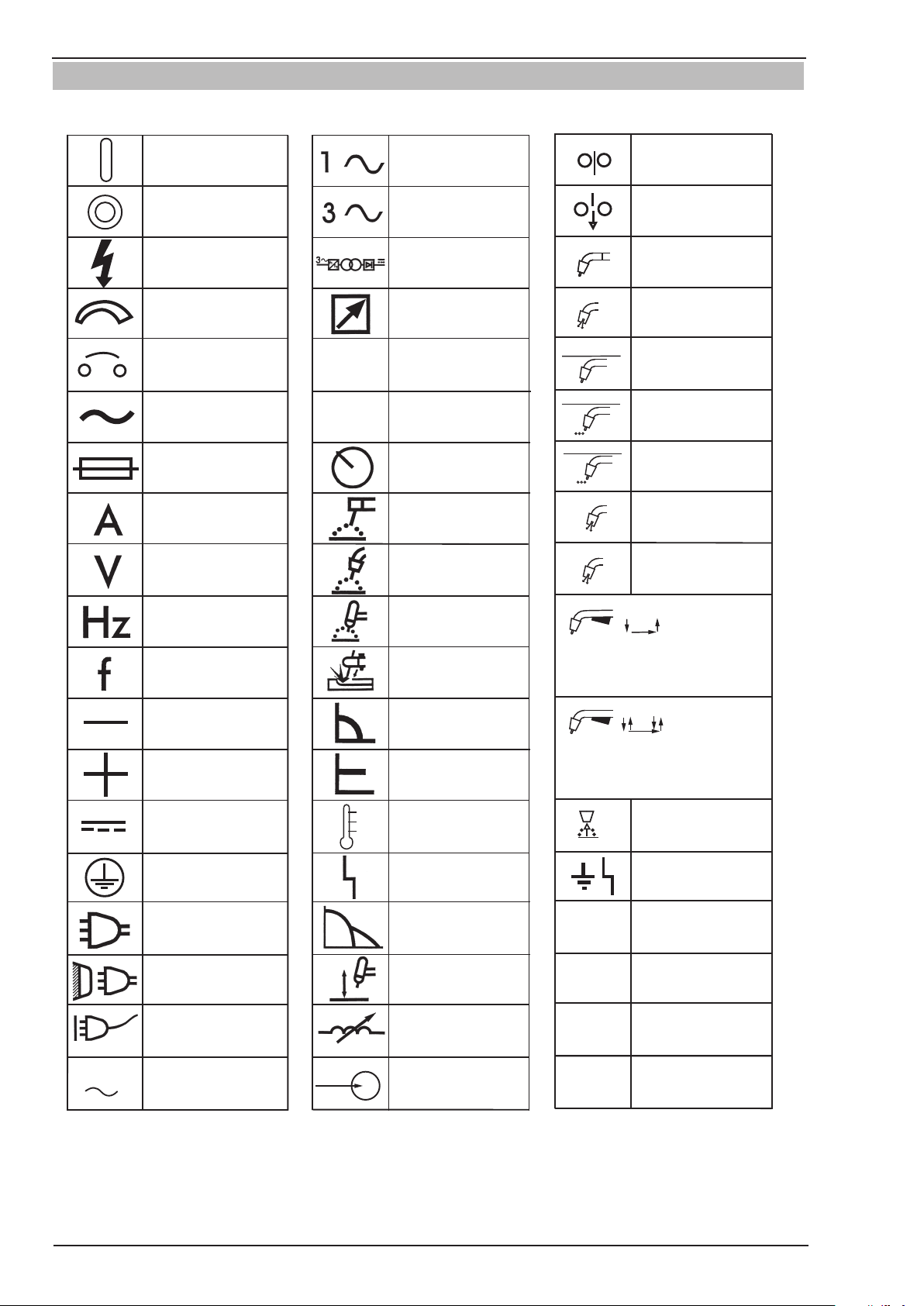
1.03 Symbol Chart
Note that only some of these symbols will appear on your model.
On
Off
Dangerous Voltage
Increase/Decrease
Circuit Breaker
AC Auxiliary Power
Fuse
Amperage
Voltage
X
%
Single Phase
Three Phase
Three Phase Static
Frequency ConverterTransformer-Rectifier
Remote
Duty Cycle
Percentage
Panel/Local
Manual Metal
Arc Welding (MMAW)
Gas Metal Arc
Welding (GMAW)
Wire Feed Function
Wire Feed Towards
Workpiece With
Output Voltage Off.
Welding Torch
Purging Of Gas
Continuous Weld
Mode
Spot Weld Mode
Spot Time
t
t2
Preflow Time
Postflow Time
t1
Hertz (cycles/sec)
Frequency
Negative
Positive
Direct Current (DC)
Protective Earth
(Ground)
Line
Line Connection
Auxiliary Power
Gas Tungsten Arc
Welding (GTAW)
Air Carbon Arc
Cutting (CAC-A)
Constant Current
Constant Voltage
Or Constant Potential
High Temperature
Fault Indication
Arc Force
Touch Start (GTAW)
Variable Inductance
2 Step Trigger
Operation
Press to initiate wirefeed and
welding, release to stop.
4 Step Trigger
Operation
Press and hold for preflow, release
to start arc. Press to stop arc, and
hold for preflow.
Burnback Time
t
Disturbance In
Ground System
IPM
MPM
Inches Per Minute
Metres Per Minute
115V 15A
Receptacle RatingAuxiliary Power
Voltage Input
V
Figure 1-1 Symbol Chart
GENERAL INFORMATION 1-6 Manual 0-5231
Art # A-10344_AB
Page 13

TRANSMIG VAF4
1.04 Declaration of Conformity
Manufacturer: CIGWELD
Address: 71 Gower St, Preston
Victoria 3072
Australia
Description of equipment: CIGWELD Transmig VAF4 wire feeder and associated accessories.
Serial numbers are unique with each individual piece of equipment and details description, parts used to manufacture a unit and date of manufacture.
The equipment conforms to all applicable aspects and regulations of the ‘Low Voltage Directive’ (Directive 73/23/
EU, as recently changed in Directive 93/68/EU and to the National legislation for the enforcement of the Directive.
National Standard and Technical Specifications
The product is designed and manufactured to a number of standards and technical requirements among them are:
• IEC60974-10applicabletoIndustrialEquipment-genericemissionsandregulations.
• AS1674Safetyinweldingandalliedprocesses.
• IEC60974-5Arcweldingequipment,Wirefeeders.
• (IEC)AS60974.1Arcweldingequipment,Weldingpowersources.
Extensive product design verification is conducted at the manufacturing facility as part of the routine design and
manufacturing process, to ensure the product is safe and performs as specified. Rigorous testing is incorporated
into the manufacturing process to ensure the manufactured product meets or exceeds all design specifications.
CIGWELD has been manufacturing and merchandising an extensive equipment range with superior performance,
ultra safe operation and world class quality for more than 30 years and will continue to achieve excellence.
Manual 0-5231 1-7 GENERAL INFORMATION
Page 14

TRANSMIG VAF4
This page intentionally blank
GENERAL INFORMATION 1-8 Manual 0-5231
Page 15
TRANSMIG VAF4
!
SECTION 2: INTRODUCTION
2.01 How to Use This Manual
To ensure safe operation, read the entire manual, including the chapter on safety instructions and warnings.
Throughout this manual, the word WARNING, CAUTION and NOTE may appear. Pay particular attention to
the information provided under these headings. These
special annotations are easily recognized as follows:
WARNING
Gives information regarding possible personal injury. Warnings will be enclosed in a
box such as this.
CAUTION
Refers to possible equipment damage. Cautions will be shown in bold type.
NOTE
Offers helpful information concerning certain
operating procedures. Notes will be shown
in italics
Additional copies of this manual may be purchased by
contacting Cigweld at the address and phone number
for your location listed in the inside back cover of this
manual. Include the Owner’s Manual number and equipment identification numbers.
2.02 Equipment Identification
The unit’s identification number (specification or part
number), model, and serial number usually appear
on a nameplate attached to the machine. Equipment
which does not have a nameplate attached to the
machine is identified only by the specification or part
number printed on the shipping container. Record these
numbers for future reference.
2.03 Receipt of Equipment
When you receive the equipment, check it against the
invoice to make sure it is complete and inspect the
equipment for possible damage due to shipping. If there
is any damage, notify the carrier immediately to file a
claim. Furnish complete information concerning damage
claims or shipping errors to the location in your area
listed in the inside back cover of this manual.
Include all equipment identification numbers as described above along with a full description of the parts
in error.
Move the equipment to the installation site before
un-crating the unit. Use care to avoid damaging the
equipment when using bars, hammers, etc., to un-crate
the unit.
Manual 0-5231 2-1 INTRODUCTION
Page 16
TRANSMIG VAF4
!
2.04 Description
The Transmig VAF4 offers both load and line voltage
compensation helping to maintain a constant wire feed
speed, even with changes in the input voltage and/or
load.
The Transmig VAF4’s sheet metal box totally encloses
the solid state control circuitry. A hinged, latched feedhead cover allows quick and easy access to the feedhead
featuring quick change feed rolls, and tool-less knobs
and clamps for changeover of guides and guns.
The Transmig VAF4 comes with an abundance of standard features including:
• anon/offrockerswitch
• 2circuitbreakersfortotalsystemprotection
• awirefeedspeedcontrol
• apowersourcevoltagecontrol
• aninchswitch
• agaspurgeswitch
• a2T/4T/Spotselectorswitch
• PCboardadjustmentsforenhancedrunincontrol
2.05 User Responsibility
This equipment will perform as per the information contained herein when installed, operated, maintained and
repaired in accordance with the instructions provided.
This equipment must be checked periodically. Defective
equipment (including welding leads) should not be used.
Parts that are broken, missing, plainly worn, distorted or
contaminated, should be replaced immediately. Should
such repairs or replacements become necessary, it is
recommended that such repairs be carried out by appropriately qualified persons approved by CIGWELD.
Advice in this regard can be obtained by contacting an
Accredited CIGWELD Distributor.
This equipment or any of its parts should not be altered
from standard specification without prior written approval of CIGWELD. The user of this equipment shall
have the sole responsibility for any malfunction which
results from improper use or unauthorized modification from standard specification, faulty maintenance,
damage or improper repair by anyone other than appropriately qualified persons approved by CIGWELD.
2.06 Transportation Methods
• asolidstateelectronicbrakefordynamicbraking
• twoquickchange,gear-drivenfeedrolls
• agasvalvesolenoid
• anisolatedguntriggerforoperatorsafety
• avarietyofadd-onoptionstoconguretheunit
for any wire-welding situation.
The Transmig VAF4 has been designed to comply with
CSA NRTL/C, NEMA EW 3, and IEC 60974-1 standards.
The instructions in the next section detail how to correctly and safely set up the machine and give guidelines
on gaining the best efficiency and quality from the Power
Source. Please read these instructions thoroughly before using the unit.
!
WARNING
ELECTRIC SHOCK can kill. DO NOT TOUCH
live electrical parts. Disconnect wire feeder
from Power Source before moving the wire
feeder.
WARNING
FALLING EQUIPMENT can cause serious
personal injury and equipment damage.
Lift unit with integrated handle at the top of the unit.
Use handcart or similar device of adequate capacity.
If using a fork lift vehicle, place and secure unit on a
proper skid before transporting.
2.07 Packaged Items
Transmig VAF4 Wirefeeder (Part No.: W3000700)
•TransmigVAF4Wirefeeder
•OperatingManual
•DriveRoll0.9-1.2mm,V-groovetted
•HandleAssembly
INTRODUCTION 2-2 Manual 0-5231
Page 17
TRANSMIG VAF4
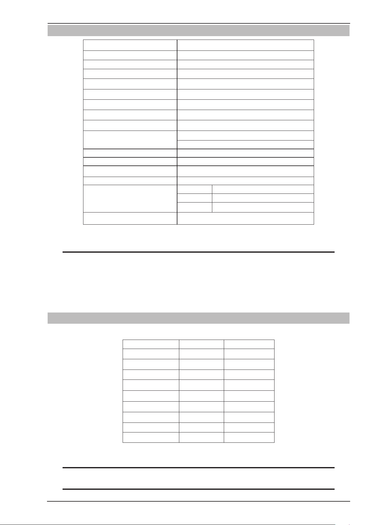
2.08 Specifications
Description Transmig VAF4 Wirefeeder
Wirefeeder Part Number W3000700
Wirefeeder Dimensions H 345mm x W 275mm x D 610mm
Wirefeeder Mass 19kg
Input Voltage 42VAC or 115VAC, 350VA
Input Voltage Tolerance ±15%
Input Frequency 50/60 Hz
Gas Solenoid Voltage 24vdc
Maximum Gas Pressure 0.7 Mpa (7 bar)
MIG Welding Output, 40°C, 10
min
Minimum Wire Feed Speed 1.2 - 1.5 MPM (47 - 59 IPM)
Maximum Wire Feed Speed 22.1 - 22.5 MPM (870 - 886 IPM)
Operating Temperature Range 0°C - 40°C
Interconnection Plug 19pin
Solid
Wire Sizes
Aluminium 0.9mm (0.035”) to 1.6mm (1/16”)
Flux Cored
450A at 60%
350A at 100%
0.8mm (0.030”) to 1.6mm (1/16”)
0.8mm (0.030”) to 2.0mm (5/64”)
Maximum Wire Spool Weight 60 lb./ 27kg
Table 2-1 Transmig VAF4 Specification
NOTE
Due to variations that can occur in manufactured products, claimed performance, voltages, ratings, all
capacities, measurements, dimensions and weights quoted are approximate only. Achievable capacities
and ratings in use and operation will depend upon correct installation, use, applications, maintenance
and service.
In the interest of continuous improvement, CIGWELD Pty. Ltd. reserves the right to change the specifications or design of any of its products without prior notice.
2.09 Optional Accessories
Feed Rolls
Wire Size Wire Type Part Number
0.6mm/ 0.8mm Hard 7977729
0.9mm/ 1.2mm* Hard 7977703
1.2mm/ 1.6mm Hard 7977346
0.8mm/ 0.9mm Soft 7977733
1.0mm/ 1.2mm Soft 7977730
1.2mm/ 1.6mm Soft 7977348
0.8mm/ 0.9mm Cored 7977734
1.2mm/ 1.6mm Cored 7977347
1.6mm/ 2.0mm Cored 7977372
Table 2-2 Feed Rolls
NOTE
Two feed rolls are required for each wire size.
NOTE
* indicates fitted as standard.
Manual 0-5231 2-3 INTRODUCTION
Page 18

TRANSMIG VAF4
Other Accessories
Accessories Part Number Description
TWECO No 4 MIG TORCH
3.6M EURO
TWECO No 4 MIG TORCH
4.5M EURO
TWECO SUPRA XT MIG
TORCH 4.0M EURO
TWECO No 4 MIG TORCH
3.6M Tweco 4
TWECO No 4 MIG TORCH
4.5M Tweco 4
TWECO SUPRA XT MIG
TORCH 4.0M Tweco 4
Interconnect Assy,19P-
19P,2M
Interconnect Assy,19P-
19P,8M
Interconnect Assy,19P-
19P,15M
OTWX412/3545
OTWX415/3545
SE400X4M16
717201
717335
SE4004M16
W4015900
W4015901
W4015902
Euro connection type, length is 3.6 metres, 400
Amps @ 60%, contact tip OTW14/45 (1.2mm)
Euro connection type, length is 4.5 metres, 400
Amps @ 60%, contact tip OTW14/45 (1.2mm)
Euro connection type, length is 4.0 metres, 450
Amps @ 60%, contact tip OTW15H/116 (1.6mm)
Tweco connection type, length is 3.6 metres, 400
Amps @ 60%, contact tip OTW14/45 (1.2mm)
Tweco 4 connection type, length is 4.5 metres, 400
Amps @ 60%, contact tip OTW14/45 (1.2mm)
Tweco connection type, length is 4.0 metres, 450
Amps @ 60%, contact tip OTW15H/116 (1.6mm)
19 pin to 19 pin, 2 metres in length, suitable for
Transmig 350i, 450i & 550i
19 pin to 19 pin, 8 metres in length, suitable for
Transmig 350i, 450i & 550i
19 pin to 19 pin, 15 metres in length,suitable for
Transmig 350i, 450i & 550i
Interconnect Assy,19P-
14P,8M
Adaptor Cable,19P-14P,
0.3M
Spool Cover Assembly W4016300
TWECO No 4 Adaptor
Assembly
Lifting Eye Kit W4016700 Electrically insulated.
Heavy Duty 4 Wheel
Trolley
Mig Pliers WSPLIER
W4016000
W4016001
W4016400
W4000001
19 pin to 14 pin, 8 metres in length,suitable for
Transmig 400i, MPM8/255H, MPM8/270K
19 pin to 14 pin, 0.3 metres in length, required for
MPM12/400K & MPM20/500P
Suitable for spools up to 300mm diameter.
Contains plastic spool cover and all necessary
mounting hardware
Tweco No 4 connection, designed for Supra XT
MIG torch SE4004M16, Tweco No 4 MIG torch
717201 & 717335. Rated at 450A @ 60%
Heavy duty, large castor wheel trolley for moving
the Wirefeeder around the work area.
Specifically designed for MIG welding applications.
Manufactured from drop forged carbon steel.
Spring loaded handle. Excellent for trimming MIG
wire or holding tips and nozzles.
Measures leg length, root gap, plate
Naka Measurement Gauge 646265
Nozzle Dip 702389
Table 2-3 Options and Accessories
INTRODUCTION 2-4 Manual 0-5231
thickness,convexity, wire and rod diameter and
height of welds.
Supplied in 450g tin. Helps to prevent the adhesion
of spatter to tips and nozzles.
Page 19
TRANSMIG VAF4
!
!
SECTION 3: INSTALLATION, OPERATION AND SETUP
3.01 Environment
These units are designed for use in environments with
increased hazard of electric shock as outlined in IEC
60974.5.
A. Examples of environments with increased hazard of
electric shock are:
1. In locations in which freedom of movement is restricted, so that the operator is forced to perform
the work in a cramped (kneeling, sitting or lying)
position with physical contact with conductive parts.
2. In locations which are fully or partially limited by
conductive elements, and in which there is a high
risk of unavoidable or accidental contact by the
operator.
3. In wet or damp hot locations where humidity or perspiration considerably reduces the skin resistance
of the human body and the insulation properties of
accessories.
B. Environments with increased hazard of electric
shock do not include places where electrically conductive parts in the near vicinity of the operator, which can
cause increased hazard, have been insulated.
3.02 Location
Be sure to locate the wirefeeder according to the following guidelines:
A. In areas, free from moisture and dust.
B. Ambient temperature between 0° C to 40° C.
C. In areas, free from oil, steam and corrosive gases.
D. In areas, not subjected to abnormal vibration or
shock.
E. In areas, not exposed to direct sunlight or rain.
F. The enclosure design of this Wire Feeder meets the
requirements of IP23S as outlined in AS 60529. This
provides adequate protection against solid objects
(greater than 12mm), and direct protection from
vertical drops. Under no circumstances should the
unit be operated or connected in a micro environment that will exceed the stated conditions. For
further information please refer to AS 60529.
G. Precautions must be taken against the Wire Feeder
toppling over. The Wire Feeder must be located on
a suitable horizontal surface in the upright position
when in use.
3.03 Ventilation
WARNING
Since the inhalation of welding fumes can
be harmful, ensure that the welding area is
effectively ventilated.
3.04 Mains Supply Voltage Requirements
CAUTION
This wirefeeder cannot be connected directly
to the mains supply. It must be connected
to a suitable wirefeeder control socket on a
power source.
3.05 Electromagnetic Compatibility
WARNING
Extra precautions for Electromagnetic
Compatibility may be required when this
Welding Power Source is used in a domestic
situation.
A. Installation and Use - Users Responsibility
The user is responsible for installing and using the
welding equipment according to the manufacturer’s
instructions. If electromagnetic disturbances are
detected then it shall be the responsibility of the user
of the welding equipment to resolve the situation with
the technical assistance of the manufacturer. In some
cases this remedial action may be as simple as earthing
the welding circuit, see NOTE below. In other cases it
could involve constructing an electromagnetic screen
enclosing the Welding Power Source and the work,
complete with associated input filters. In all cases,
electromagnetic disturbances shall be reduced to the
point where they are no longer Trouble-some.
NOTE
The welding circuit may or may not be
earthed for safety reasons. Changing the
earthing arrangements should only be authorised by a person who is competent to
assess whether the changes will increase the
risk of injury, e.g. by allowing parallel welding current return paths which may damage
the earth circuits of other equipment. Further
guidance is given in IEC 60974-13 Arc Welding Equipment - Installation and use (under
preparation).
Manual 0-5231 3-1 INSTALLATION, OPERATION AND SETUP
Page 20

TRANSMIG VAF4
B. Assessment of Area
3. Welding Cables
Before installing welding equipment, the user shall make
an assessment of potential electromagnetic problems
in the surrounding area. The following shall be taken
into account.
1. Other supply cables, control cables, signalling and
telephone cables; above, below and adjacent to the
welding equipment.
2. Radio and television transmitters and receivers.
3. Computer and other control equipment.
4. Safety critical equipment, e.g. guarding of industrial
equipment.
5. The health of people around, e.g. the use of pacemakers and hearing aids.
6. Equipment used for calibration and measurement.
7. The time of day that welding or other activities are
to be carried out.
8. The immunity of other equipment in the environment:
the user shall ensure that other equipment being
used in the environment is compatible: this may
require additional protection measures.
The size of the surrounding area to be considered
will depend on the structure of the building and other
activities that are taking place. The surrounding area
may extend beyond the boundaries of the premises.
C. Methods of Reducing Electromagnetic Emissions
The welding cables should be kept as short as
possible and should be positioned close together
but never coiled and running at or close to the floor
level.
4. Equipotential Bonding
Bonding of all metallic components in the welding
installation and adjacent to it should be considered.
However, metallic components bonded to the work
piece will increase the risk that the operator could
receive a shock by touching the metallic components
and the electrode at the same time. The operator
should be insulated from all such bonded metallic
components.
5. Earthing/grounding of the Work Piece
Where the work piece is not bonded to earth for
electrical safety, nor connected to earth because
of its size and position, e.g. ship’s hull or building
steelwork, a connection bonding the work piece to
earth may reduce emissions in some, but not all
instances. Care should be taken to prevent the earthing of the work piece increasing the risk of injury
to users, or damage to other electrical equipment.
Where necessary, the connection of the work piece
to earth should be made by direct connection to
the work piece, but in some countries where direct
connection is not permitted, the bonding should be
achieved by suitable capacitance, selected according
to national regulations.
1. Mains Supply
Welding equipment should be connected to the
mains supply according to the manufacturer’s
recommendations. If interference occurs, it may
be necessary to take additional precautions such
as filtering of the mains supply. Consideration
should be given to shielding the supply cable
of permanently installed welding equipment in
metallic conduit or equivalent. Shielding should be
electrically continuous throughout its length. The
shielding should be connected to the Welding Power
Source so that good electrical contact is maintained
between the conduit and the Welding Power Source
enclosure.
2. Maintenance of Welding Equipment
The welding equipment should be routinely
maintained according to the manufacturer’s
recommendations. All access and service doors and
covers should be closed and properly fastened when
the welding equipment is in operation. The welding
equipment should not be modified in any way except
for those changes and adjustments covered in the
manufacturer’s instructions.
6. Screening and Shielding
Selective screening and shielding of other cables
and equipment in the surrounding area may alleviate
problems of interference. Screening the entire
welding installation may be considered for special
applications.
INSTALLATION, OPERATION AND SETUP 3-2 Manual 0-5231
Page 21
TRANSMIG VAF4
Amps /
(Wirespeed)
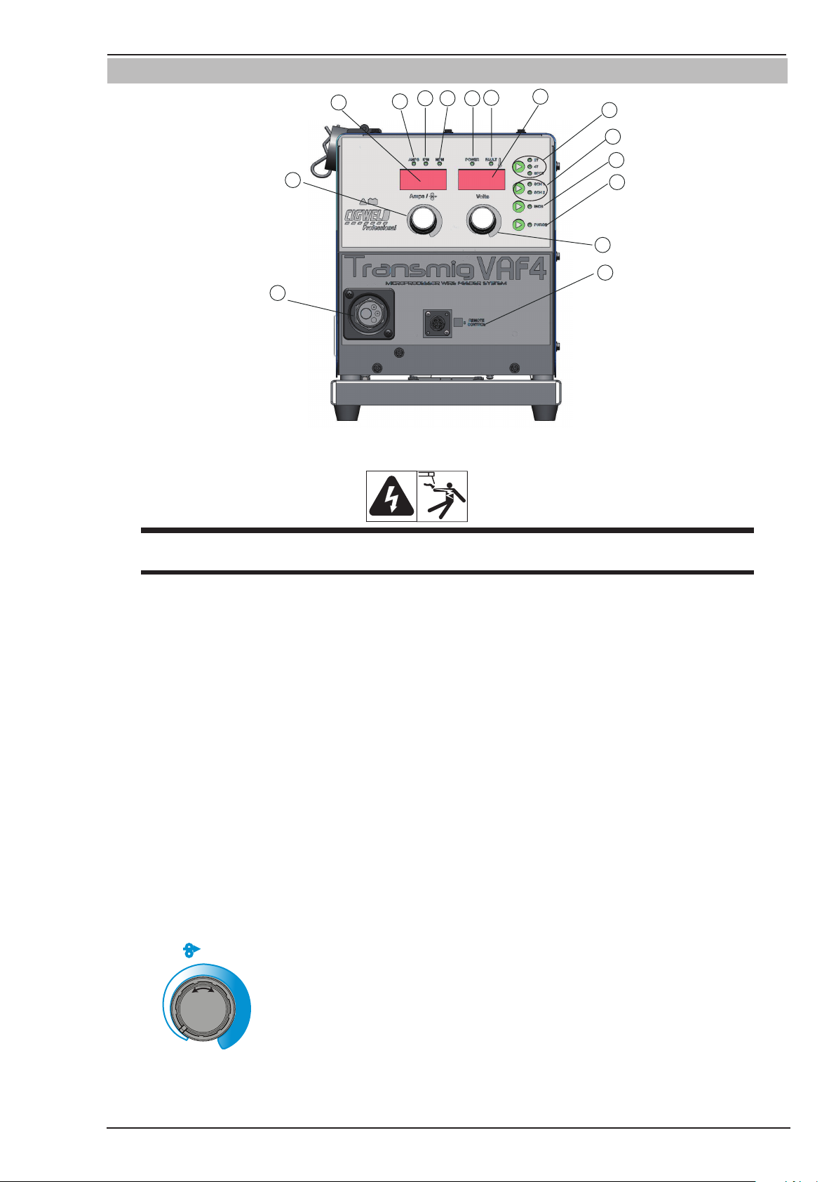
3.06 Front Panel Controls, Indicators and Features
14
54
1
8
6
3
2
Art # A-11255_AB
9
10
11
12
13
7
15
Figure 3-1 Front Panel View
WARNING
DO NOT TOUCH the electrode wire while it is being fed through the system. The electrode wire will be
at welding voltage potential.
1. POWER Indicator
The red power indicator will be illuminated when the Wirefeeder is turned ON and indicates the presence of power.
2. FAULT Indicator
The yellow fault indicator will be illuminated when any faults are detected. Should a fault condition occur refer to
Subsections 3.30, 3.31, 4.05 or 4.08 for further information.
If the Fault indicator is flashing whilst welding refer to Subsection 3.31 as the motor overload protection is active.
3. AMPS Indicator
The red AMPS indicator will be illuminated when the Left Display displays the amperage.
4. IPM Indicator
The red IPM indicator will be illuminated when the Left Display displays WFS in Inches Per Minute (IPM).
5. MPM Indicator
The red MPM indicator will be illuminated when the Left Display displays WFS in Metres Per Minute (MPM).
6. Left Knob
Left Knob
The control knob adjusts Wire Feed Speed (WFS) (which in turn adjusts the output current by turning the amount
of MIG wire delivered to the welding arc). The optimum WFS required is dependent on the type of welding application. The value may also be adjusted while a weld is in progress – if this occurs, the left display will briefly
Manual 0-5231 3-3 INSTALLATION, OPERATION AND SETUP
Page 22
TRANSMIG VAF4
plication. The value may also be adjusted while a weld is in progress – if this occurs, the left display will briefly
switch to show the adjusted value as the knob is turned, and will automatically revert back to show the weld
current measurements when the knob is not being turned. Turn the left knob either clockwise to increase WFS or
counterclockwise to decrease WFS by increments of 0.1MPM. To increment in steps of 1 MPM whilst holding the
left knob depressed turn it either clockwise to increase WFS or counterclockwise to decrease WFS.
The Left digital meter display option can be changed either via the Advanced Features Menu (refer to Subsection
3.08)
OR
By simply depressing the Left Amps control knob for 3 seconds whilst welding, then by releasing the knob and
then holding it depressed for a further 3 seconds will increment to the next available display option that is shown
on the left digital display. i.e. Amps WFS ---- (blank).
Press Left Knob (Amps) and Right Knob (Volts) for 1.2 seconds to enter or exit from the advanced programming
mode. Please refer to Subsection 3.08 for Advanced Features Details.
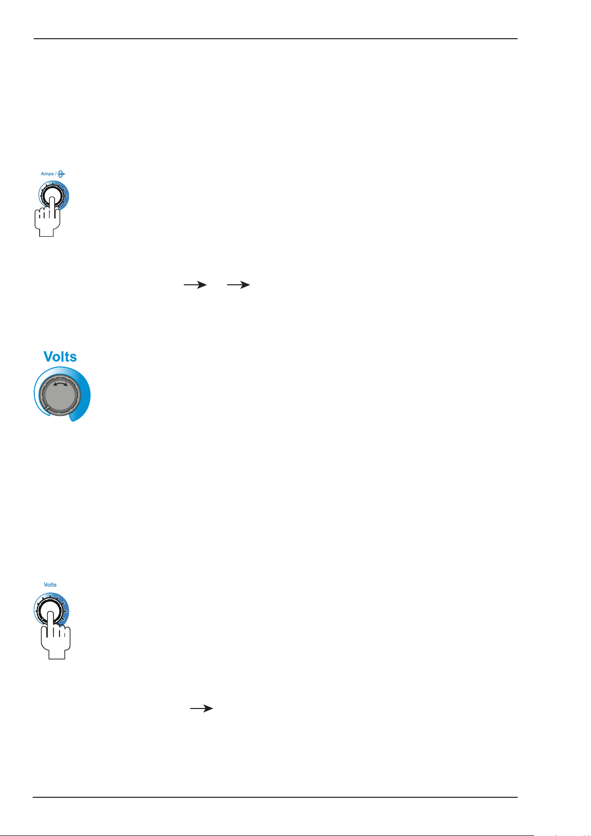
7. Right Knob
Right Knob
The control knob adjusts the output voltage of the power source. The welding voltage is increased by turning the
knob clockwise or decreased by turning the knob counter-clockwise. The value may also be adjusted while a weld
is in progress – if this occurs, the right display will briefly switch to show the adjusted value as the knob is turned,
and will automatically revert back to show the weld voltage measurements when the knob is not being turned.
Turn the right knob either clockwise to increase voltage or counterclockwise to decrease voltage by increments
of 0.1V. To increment in steps of 1V whilst holding the right knob depressed turn it either clockwise to increase
WFS or counterclockwise to decrease WFS.
The Right digital meter display option can be changed either via the Advanced Features Menu (refer to Subsection
3.08)
OR
By simply depressing the Right Amps control knob for 3 seconds whilst welding, then by releasing the knob and
then holding it depressed for a further 3 seconds will increment to the next available display option that is shown
on the right digital display. i.e. VARC ---- (blank).
Press Left Knob (Amps) and Right Knob (Volts) for 1.2 seconds to enter or exit from the advanced programming
mode. In advanced programming mode, turning the knob clockwise to increase and counter-clockwise to decrease
the value on right display. Please refer to Subsection 3.08 for Advanced Features Details.
INSTALLATION, OPERATION AND SETUP 3-4 Manual 0-5231
Page 23
TRANSMIG VAF4
8. Left Digital Display
Left display is a 4- digit display.
In advanced programming mode, this display is used to display advanced features details or simply "----". Please
refer to Subsection 3.08 for Advanced Features Details.
When welding, this digital meter will display WFS in Inches Per Minute (IPM) or Metres Per Minute (MPM) and
actual welding amperage of the power source; it can also simply display "----" when the VAF4 is connected to a
power source without a control signal on pin U of the 19 pin interconnection. The VAF4 uses this signal on pin U
of the 19 pin interconnection to display welding amps, if this signal is not present from the power source, set the
display to show "----". Press left knob and select the information on left display. At times of non-welding, the digital
meter will display a pre-set (preview) WFS value. This value can be adjusted by turning the Left Knob (Control No. 6).
At the completion of welding, the digital meter will hold the last recorded value for a period of approximately 10
seconds. The meter will hold the value until: (1) any of the front panel controls are adjusted in which case the
unit will revert to preview mode, (2) welding is recommenced, in which case actual welding amperage will be
displayed, or (3) a period of 10 seconds elapses following the completion of welding in which case the unit will
return to preview mode.
The display is also used for providing error messages to the user. Please refer to Subsection 4.05 for Error Codes
and Remedies.
9. Right Digital Display
Right display is a 4- digit display.
This digital meter is used to display the pre-set (preview) Voltage in MIG mode and actual welding voltage of the
power source or simply "----" when the VAF4 is connected to a power source without a control signal on pin C of
the 19 pin interconnection. The VAF4 uses this signal on pin C of the 19 pin interconnection to display welding
volts, if this signal is not present from the power source, set the display to show "----". Press right knob and select
the information on right display. At times of non-welding, the digital meter will display a pre-set (preview) value
of Voltage. This value can be adjusted by turning the Right Knob (Control No 7).
At the completion of welding, the digital meter will hold the last recorded voltage value for a period of approximately 10 seconds in all modes. The voltage meter will hold the value until: (1) any of the front panel controls are
adjusted in which case the unit will revert to preview mode, (2) welding is recommenced, in which case actual
welding voltage will be displayed, or (3) a period of 10 seconds elapses following the completion of welding in
which case the unit will return to preview mode.
The display is also used for providing error messages to the user and showing other information. Please refer to
Subsection 4.05 for Error Codes and Remedies.
10. 2T - 4T- SPOT Trigger Mode Control Button
Press and release the button to change the selected operating mode of the trigger. The selected mode can be “2T”,
“4T” or "Spot” operation. The red indicator next to the button will illuminate to identify which mode is selected.
In the 4T mode once the weld has been started you can release the trigger and continue welding until the trigger
is activated again or the welding arc is broken to stop the welding arc. Please refer to Subsection 3.25 - 3.28 for
more details.
Manual 0-5231 3-5 INSTALLATION, OPERATION AND SETUP
Page 24
TRANSMIG VAF4
Note
In Advanced Features Mode Trigger Mode and SCH1-SCH2 can't be changed. In Spot Mode Stitch
Mode is not available. Crater is only available in 4T Trigger Mode.
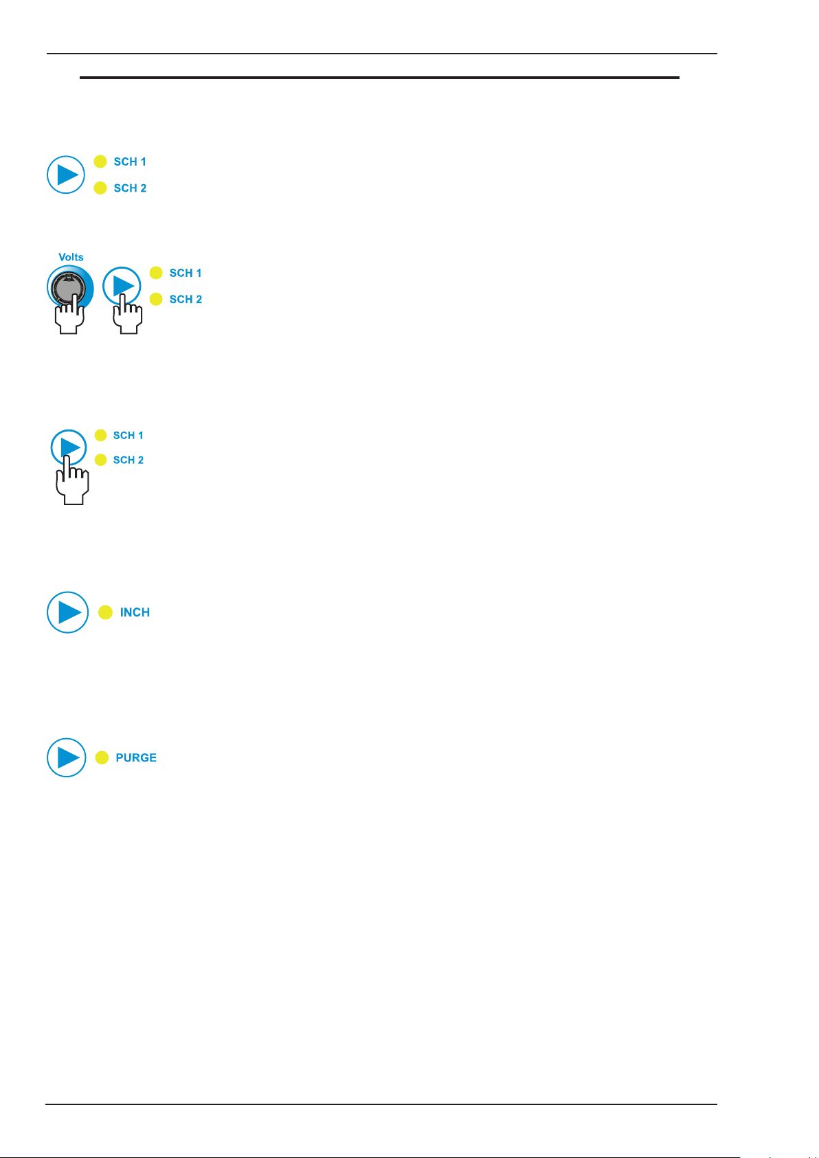
11. SCH 1-SCH 2 Button
This allows the user to save parameter settings in either Schedule 1 (SCH 1) or Schedule 2 (SCH 2) locations. Press
the button to select either SCH 1 or SCH 2. The red indicator will illuminate to identify which schedule is selected.
Right Knob
Adjust the wire speed and weld volts, along with parameters such as burnback, pre flow, post flow etc, to the
desired setting. Whilst holding the volts knob depressed at the same time press the SCH 1-SCH 2 button for 1.8
seconds to save the schedule. The SCH 1 or SCH 2 LED will flash 3 times to indicate the save has been successful.
Note that all adjustable parameters are saved with each schedule.
If the user wishes to load settings saved in either SCH 1 or SCH 2 locations, press and release the SCH 1-SCH
2 button to select either SCH 1 or SCH 2, the red indicator will illuminate to identify which Schedule is selected.
12. INCH Button
After turning the power ON, press this button and hold it to start cold feeding. Left display shows actual WFS and
right display shows INCH. If the user wishes to adjust WFS, turn left knob and left display shows preset WFS. 1
second later, it shows actual WFS. Release the button when it feeds the wire to the torch.
13. PURGE Button
This button is used to initiate gas line purge function to fill the gas line with the shielding gas from the connected
gas cylinder. Press and hold the button depressed to start gas purge function, at which time a countdown timer
will show in left display indicating the number of seconds remaining. You can stop the gas purge any time during
the 30 seconds by releasing the button.
14. MIG Torch Adaptor
The MIG Torch adaptor is the connection point for the MIG welding Torch. Connect the MIG Torch by pushing the
MIG Torch connector into the brass MIG Torch adaptor firmly and screwing the plastic MIG Torch nut clockwise
to secure in position. To remove the MIG Torch simply reverse these directions.
INSTALLATION, OPERATION AND SETUP 3-6 Manual 0-5231
Page 25
TRANSMIG VAF4
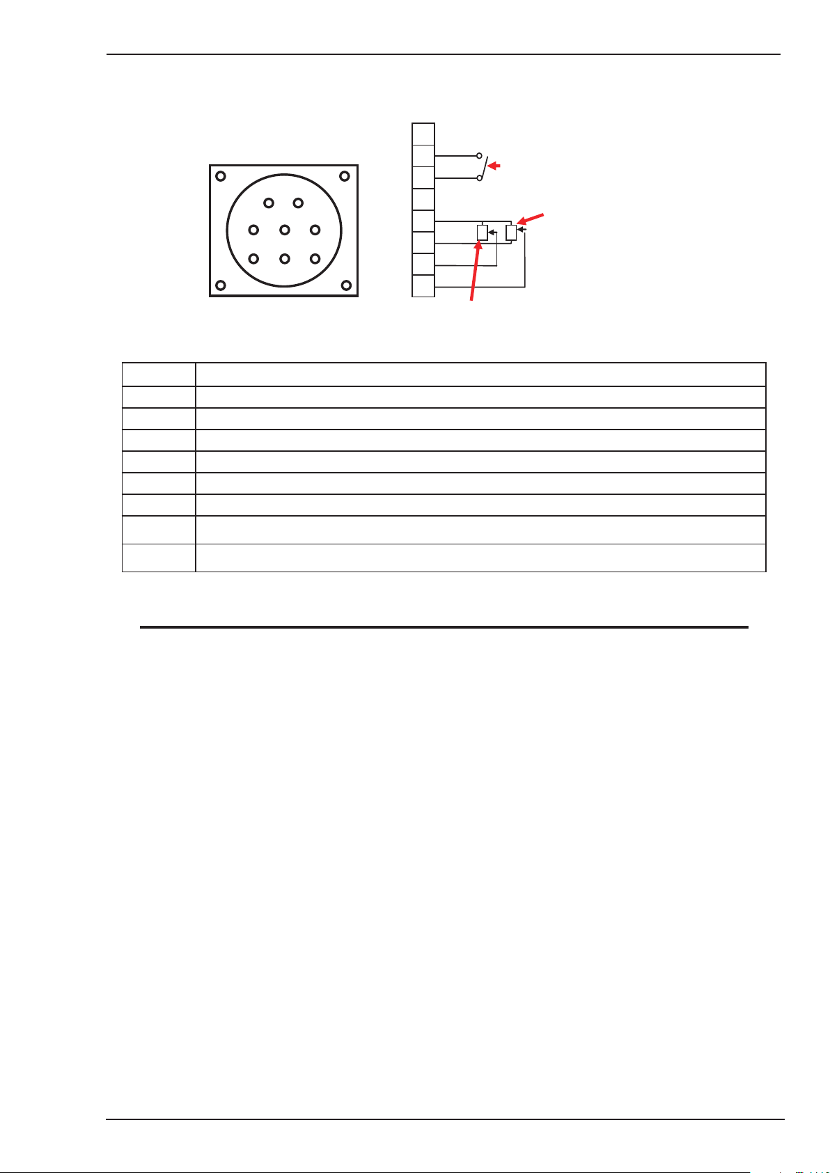
15. Remote Control Socket
The 8 pin Remote Control Socket is used to connect remote control devices to the welding power source. To make
connections, align keyway, insert plug, and rotate threaded collar fully clockwise.
1
2
3
1
2
5
8
3
4
6
7
4
5
6
7
8
Remote Wirespeed in GMAW mode
Figure 3-2 Remote Control Socket
Trigger Switch
W
V
Remote Volts in
GMAW Mode
Socket Pin
1 Not connected
2 Trigger Switch Input
3 Trigger Switch Input
4 Not connected
5 5k ohm (maximum) connection to 5k ohm remote control potentiometer.
6 Zero ohm (minimum) connection to 5k ohm remote control potentiometer.
7 Wiper arm connection to 5k ohm remote control Wirespeed MIG mode potentiometer.
8 Wiper arm connection to 5k ohm remote control Volts MIG mode potentiometer.
Function
Table 3-1 Pin Function in Remote Control Socket
NOTE
The remote/ local setting in Advanced Features Menu should be set to remote for the remote wire feeder
amperage/voltage controls to be operative.
Manual 0-5231 3-7 INSTALLATION, OPERATION AND SETUP
Page 26
TRANSMIG VAF4
Keyway
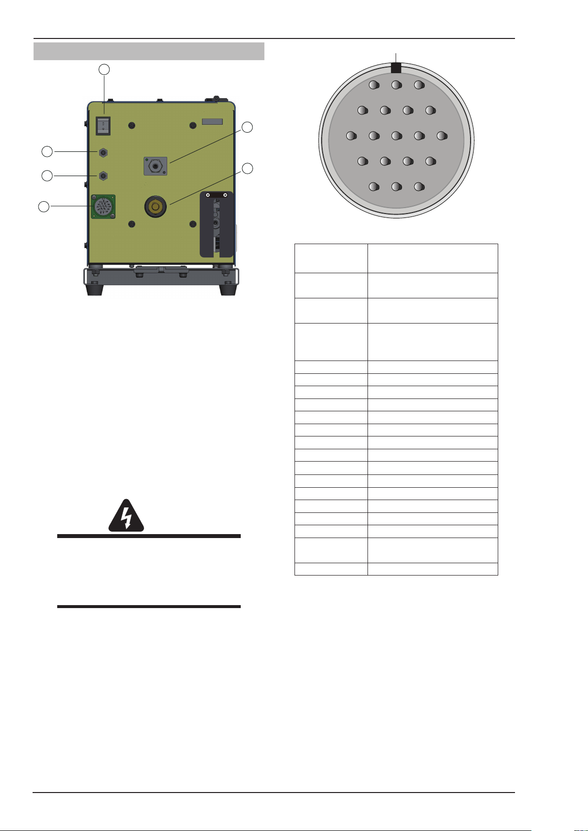
3.07 Rear Panel Controls and Features
16
17
20
21
18
Art# A-11256
19
Figure 3-3 Rear Panel View
16. ON/ OFF Switch
Press this switch to turn ON or turn OFF the Wirefeeder.
17. Gas Inlet
Gas inlet allows to connect the shield gas.
18. Control Cable Socket
The control cable connects to the power source at this
19-pin amphenol connector. It contains the signals required to allow the welding power source and the wire
feeder to work together as a system.
WARNING
The protective earth ground (pin G) of the
control cable is established ONLY when the
power source is properly grounded. See the
power source owner’s manual for proper
grounding methods.
19. Welding Cable Connector
This connector allows to connect welding cable with
Wirefeeder. Please make sure that it is secured firmly,
or it will heat and generate arc.
20. 4A Circuit Breaker
This circuit breaker protects the wirefeeder from electrical faults on the 115VAC circuit. In the event of a fault
occuring this circuit breaker will trip (pop out). A short
cooling period must be allowed before an attempt is
made to reset it by pressing it back in. Refer to Subsection 4.08 for further details.
L
KUNB
HS RD
A
M
CPVTJ
EFG
Figure 3-4 Pin Identification
Control Cable
Pin
A
B
C
D
E
F
G
H
J
K
L
M
N
P
R
S
T
U
V
Contactor + (Shorted to B
to turn ON Power Source)
Contactor- (Shorted to A to
turn ON Power Source)
Voltage Feedback ( 1
Volt is 10 Arc Volts)
Not Used
115 VAC Hot
42VAC and 115VAC Neutral
Protective Earth Ground
Remote Control Maximum
Remote Control Signal
Not Used
Power Source Common
Arc Established (= +15 VDC)
Power Source Select Line
Not Used
Not Used
42VAC Live Wire
Not Used
Current Feedback (1 Volt
is 100 Arc Amps)
Not Used
Function
Table 3-2 Control Cable Pin Functions
21. 8A Circuit Breaker
This circuit breaker protects the wirefeeder from electrical faults on the 42VAC circuit. In the event of a fault
occuring this circuit breaker will trip (pop out). A short
cooling period must be allowed before an attempt is
made to reset it by pressing it back in. Refer to Subsection 4.08 for further details.
INSTALLATION, OPERATION AND SETUP 3-8 Manual 0-5231
Page 27
TRANSMIG VAF4
3.08 Advanced Features Mode
Enter Advanced Features Mode by pressing both the left knob and right knob at the same time for more than 1.2
seconds.
NOTE
In Advanced Features Mode the Trigger Mode Control Button, SCH 1-SCH 2 button is inactive.
Exit Advanced Features Mode by pressing both the left knob and right knob at the same time for more than 1.2
seconds to Save the Settings and exit advanced features mode. Note if there has been no user input for 30 seconds,
the VAF4 will save settings and automatically exit advanced programming mode.
Advanced Feature Left Display
Feature Description
Local / Remote
This is used to select local panel
control on the Wirefeeder, or remote
control from the 8 pin remote
control socket on the front of the
Wirefeeder
Default Local / Remote = Local
If MIG Remote is selected but no remote control device is connected to the 8 pin
control socket then the wirefeed speed will be 1.3MPM (minimum wirespeed) and
Pre Flow
This is used to provide gas to the
weld zone prior to the wire striking
an arc.
Default Pre Flow = 0.1 sec
Run In
(Creep wirefeed speed)
This is used to change Wirespeed to
a percentage of the value set by the
operator. It can improve arc starts
by controlling the wire speed at the
instant the wire touches the base
Default Run In = 70%
metal.
For example if you have 12m/min set speed and have 50% selected for Run-in
Speed, the speed of the wire will be 6m/min until the arc is established. Once the
arc is established, the speed ramps up to the set speed at the rate set (12m/min)
Right Display
Parameter / Selection
Local / Remote
the voltage will be 14V (minimum volts).
0.0 – 5.0 seconds
30 – 150% of
Wirefeeder Speed
Setting
with Ramp Time described below.
Manual 0-5231 3-9 INSTALLATION, OPERATION AND SETUP
Page 28

TRANSMIG VAF4
Advanced Feature Left Display
Feature Description
Ramp Time
This is used to set the time to ramp
from the creep wire feed speed to
the selected wirefeed speed setting.
Default Ramp Time = 0.2 sec
This is used to adjust the post
gas flow time once the arc has
Default Post Flow = 0.1 sec
This is used to adjust the amount
of MIG wire that protrudes from the
MIG torch after the completion of
MIG welding (commonly referred to
Default Burn Back = 0.15 sec
This is used to fill in the “crater” at
the end of the weld. It only works
with 4T mode and the Crater Volts /
Crater Wirefeed Speed must be set.
Default Crater = Off
(only if Crater mode is ON)
This sets the reduced volts during
crater operation in 4T at the end of
Default Crater Volts = 70%
An example is if Preview Volts is
set to 26V and crater volts is set to
70% crater volts will be 18.2V. Note
minimum crater volts is determined
by minimum preview voltage of
Post Flow
extinguished.
Burn Back
as stick out)
Crater
Crater Volts
the weld.
wirefeeder.
Ramp Time plus Run In is used to optimize arc starting characteristic.
This control is used to dramatically reduce weld porosity at the completion of the
If the Burn Back time is set too long, the MIG wire may burn back to the tip of the
Right Display
Parameter / Selection
0.1 to 1.0 seconds
0.0 – 30 seconds
weld.
0.00 to 1.00
seconds
MIG torch.
Crater Mode ON /
OFF
0 – 100% of
Welding Volts
Setting
INSTALLATION, OPERATION AND SETUP 3-10 Manual 0-5231
Page 29

TRANSMIG VAF4
Advanced Feature Left Display
Feature Description
Crater Wirefeed Speed
(only if Crater mode is ON)
This sets the reduced wire speed
during crater operation in 4T at the
end of the weld.
Default Crater Wirefeed Speed =
An example is if Preview Wirefeed
speed is set to 14MPM and crater
wirefeed speed is set to 70%
crater wirefeed speed will be
9.8MPM. Note minimum crater
wirefeed speed is determined by
minimum preview wirefeed speed of
This is used to weld two thin plates
together by melting the top &
bottom plates together to form a
nugget between them. The weld time
is set by the Spot Time.
Default Spot Time = 2.0 sec
70%
wirefeeder.
Spot Time
Right Display
Parameter / Selection
0 – 100% of
Welding Wirefeed
Speed Setting
0.1 to 20.0 seconds
Stitch feature is not available in spot mode.
Stitch Mode
This is used to weld two or more
components by stitch or interval
weld together. The weld time is set
by the Stitch Time and the non weld
time is set by the Dwell Time (off
time).
Default Stitch Mode = Off
Stitch Time
(only if Stitch mode is ON)
This sets the “welding on” time in
Stitch mode.
Default Stitch Time = 2.0 sec
Dwell Time
(only if Stitch mode is ON)
This sets the “welding off” time in
Stitch mode.
Default Dwell Time = 0.5 sec
Stitch Mode ON /
OFF
Stitch is only available in 2T or 4T modes.
0.2 to 4.0 seconds
0.1 to 1.0 seconds
Manual 0-5231 3-11 INSTALLATION, OPERATION AND SETUP
Page 30

TRANSMIG VAF4
Advanced Feature Left Display
Feature Description
Wirefeed Speed Units
This allows setting of the Wirefeed
Speed Meter to display in IPM or
Default Wirefeed Speed = MPM
Arc Hours Accumulated Run Time
A Read Only display of the total of
actual arc hours.
Left Display Type
This allows the user to select what
is shown on the LEFT Display when
With some power sources, it may
not be possible to display welding
amps on the VAF4 display when
welding, in this case, set the display
to wirefeed speed (WFS) or Blank
Default Left Display = AMPS
Right Display Type
This allows the user to select what is
shown on the RIGHT Display when
With some power sources, it may
not be possible to display welding
volts on the VAF4 display when
welding, in this case, set the display
to Blank (BLNK)
Default Left Display = VARC
MPM units.
welding.
(BLNK)
welding.
Right Display
Parameter / Selection
IPM (inches per
minute)
MPM (metres per
minute)
0.0 – 999.9 hours
(It will rollover to 0
once 999.9 hours
have been reached.)
Display AMPS when
welding or
Display WIREFEED
SPEED when
welding or
Display BLANK
when welding
Display ARC VOLTS
when welding or
Display BLANK
when welding
INSTALLATION, OPERATION AND SETUP 3-12 Manual 0-5231
Page 31

TRANSMIG VAF4
Advanced Feature Left Display
Restore Factory Defaults 1
This resets all the user adjustable
values in this table (except Arc
Hour Accumulated Runtime) to the
Factory Default Values.
Factory Default Setting
Right Display
Feature Description
Parameter / Selection
Restore Factory
Default No / YES
caution
Schedule SCH1 & SCH2 settings will be reset to factory default
settings when YES is selected with Restore Factory Defaults.
Exit Advanced Features Mode: by pressing both the left knob and right knob at the
same time for more than 1.2 seconds to Save the Settings and exit advanced features
mode. Note if there has been no user input for 30 seconds, the VAF4 will save settings
and automatically exit advanced programming mode.
Table 3-3 Advanced Features
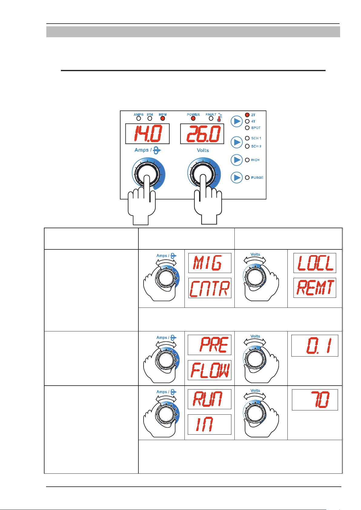
Factory Default Setting of Non-Schedule: Trigger mode: 2T; Wirefeed speed: 14.0 MPM; Voltage: 26.0V.
Suits Autocraft LW1-6, 0.9mm Hard Wire with Shielding Gas:- 91.9% Ar, 5% CO
, 3.1% O2.
2
Factory Default Setting of Schedule 1: Wirefeed speed: 11.5 MPM; Voltage: 29.0V.
Suits Autocraft LW1-6, 1.2mm Hard Wire with Shielding Gas:- 75 - 80% Ar, 20 - 25% CO
.
2
Factory Default Setting of Schedule 2: Wirefeed speed: 9.0 MPM; Voltage: 29.0V.
Suits Verti-Cor 3XP, 1.6mm Flux Cored Wire with Shielding Gas:- 75 - 80% Ar, 20 - 25% CO
Advanced Feature Left Display
Feature
Right Display
(Default)
Comments
.
2
Description
MIG Control MIG/CNTR LOCL
Pre Flow PRE/FLOW 0.1
Run In RUN/IN 70
Ramp Time RAMP/TIME 0.2
Post Flow POST/FLOW 0.1
Burn Back BURN/BACK 0.15
Crater CRAT OFF Only in 4T Mode
Crater Volts CRAT/ VOLT 70
Crater Wirefeed Speed CRAT/ WFS 70
Spot Time SPOT/TIME 2.0 Only in Spot Mode
Stitch Mode STCH OFF Only in 2T & 4T Modes
Stitch Time STCH/TIME 2.0 Only when Stitch is ON
Dwell Time DWEL/TIME 0.5 Only when Stitch is ON
Wirefeed Speed Units WFS/UNIT MPM
Left Display Type LEFT/DISP AMPS
Right Display Type RGHT/DISP VARC
Table 3-4 Factory Default Setting
Only when in 4T Mode
and Crater is ON
Only when in 4T Mode
and Crater is ON
Manual 0-5231 3-13 INSTALLATION, OPERATION AND SETUP
Page 32

TRANSMIG VAF4
3.09 Wirefeeder Configuration for Different Power Sources
WARNING
There are dangerous voltage and power levels inside this product. Turn OFF wirefeeder and disconnect
from the power source before removing cover from wirefeeder.
The factory default setting for the wirefeeder is set for the Transmig 350i & Transmig 450i power sources. If a
different power source is being used then the user will need to set the Display PCB DIP switch as to Table 3-5
according to the power source being used.
Art # A-11257
DIP Switch
Display PCB
Figure 3-5 DIP Switch on Display PCB
S3S4S5 Vmin Vmax Vsetmin(J&K) Vsetmax(J&K) Welder
S3=Off(0), S4=Off(0), S5=Off(0) 14 50 3.182 11.364 Transmig 550i
S3=On(1), S4=Off(0), S5=Off(0) 10 44 2.273 10 Transmig 500i
Transmig 400i (Refer to
S3=Off(0), S4=On(1), S5=Off(0) 10 36 0 10
S3=On(1), S4=On(1), S5=Off(0) 14 40 3.182 9.091 Transmig 350i & 450i (default)
S3=Off(0), S4=Off(0), S5=On(1) 15 40 0 -4.8
S3=On(1), S4=Off(0), S5=On(1) 15 30 0 5.5 MPM8/270 & MPM8/255
S3=Off(0), S4=On(1), S5=On(1) Spare
S3=On(1), S4=On(1), S5=On(1) 8 50
Section 3.24 to override Arc
Establish signal for this welder.
MPM20/500 & MPM12/400
(Refer to Note)
User Type Setting (The
Service Manual outlines
how to set the wirefeeder
for other Power Sources.)
Table 3-5 Voltage Setting
NOTE
When S6=ON(1), calibration functions in Advanced Features Mode is enabled; when S6=OFF(0), calibration functions are disabled.
NOTE
When S1=OFF(0),S2=OFF(0), WFS Setting is applicable for Transmig VAF4 and it ranges from 1.3
MPM to 22.2 MPM.
NOTE
An adaptor cable is required for connection to MPM20/500 or MPM12/400 Engine Drive Power Sources.
INSTALLATION, OPERATION AND SETUP 3-14 Manual 0-5231
Page 33

TRANSMIG VAF4
3.10 Attaching the MIG Torch (Euro)
Fit the MIG Torch to the power source by pushing the MIG torch connector into the MIG torch adaptor and screwing the plastic torch nut clockwise to secure the MIG torch to the MIG torch adaptor.
MIG Torch Connector
Art # A-11341
MIG Torch Adaptor
Figure 3-6 Attaching MIG Torch (Euro)
3.11 Installing Handle Assembly
!
WARNING
This handle is not designed to lift wirefeeder by mechanical means. Handle is to be used for Lifting by
Hand Only.
For Mechanical Lifting use Lifting Eye Kit W4016700.
The following components are included:
Description Quantity
Handle Assembly 1
Bolt, M10 × 50 (with torque 45~59 N.m.) 2
Flat Washer, M10 (with torque 45~59 N.m.) 4
Spring Washer, M10 (with torque 45~59 N.m.) 2
Nut, M10 (with torque 45~59 N.m.) 2
Table 3-6 Handle Assembly
Manual 0-5231 3-15 INSTALLATION, OPERATION AND SETUP
Page 34

TRANSMIG VAF4
Handle Assembly
!
Handle Assembly
Install the handle assembly as below:
Secure the handle assembly to the base assembly with M10 x 50 Bolts, M10 Flat Washers, M10 Spring Wash-
ers and M10 Nuts as shown in Figure 3-7.
Bolt, M10 × 50
Flat Washer, M10
Spring Washer, M10
Nut, M10
Art # A-11471_AB
Figure 3-7 Installing Handle Assembly
warning
Fully tighten all the fasteners with torque 45~59 N.m.
Refer to the figure below for the assembled handle assembly:
Figure 3-8 Assembled Handle Assembly
Art # A-11472_AB
INSTALLATION, OPERATION AND SETUP 3-16 Manual 0-5231
Page 35

TRANSMIG VAF4
Bolt, M8 × 40
!
Lifting Eye
3.12 Installing Lifting Eye Kit (Optional)
The following components are included:
Description Quantity
Lifting Eye 1
Insulator Plate 1
Bolt, M8 × 40 (with torque 45~59 N.m.) 2
Flat Washer (smaller), M8 (with torque 45~59 N.m.) 2
Flat Washer (larger), M8 (with torque 45~59 N.m.) 2
Insulator Washer, M8 (with torque 45~59 N.m.) 2
Spring Washer, M8 (with torque 45~59 N.m.) 2
Nut, M8 (with torque 45~59 N.m.) 2
Table 3-7 Lifting Eye Kit
Install the lifting eye as below:
1. Loosen the M10 x 50 Bolts, M10 Flat Washers, M10 Spring Washers and M10 Nuts with 17mm wrench
that secure the handle assembly and remove the handle assembly and fixings from the base assembly.
Refer to Figure 3-7.
2. Use 14mm wrench to secure the lifting eye and insulator plate to the base assembly using the M8 x 40
Bolts, M8 Flat Washers, M8 insulator washers, M8 Spring Washers and M8 Nuts as supplied with this kit.
Flat Washer
(smaller), M8
Insulator Plate
Art # A-11473_AB
Lifting Eye
Insulator Washer, M8
Flat Washer (larger), M8
Spring Washer, M8
Nut, M8
Figure 3-9 Installing Lifting Eye
WARNING
Fully tighten all the fasteners with torque 45~59 N.m.
Refer to the figure below for the assembled lifting eye.
Art # A-11474_AB
Figure 3-10 Assembled Lifting Eye
Manual 0-5231 3-17 INSTALLATION, OPERATION AND SETUP
Page 36

TRANSMIG VAF4
3.13 Installing Tweco No. 4 Adaptor (Optional)
!
WARNING
There are dangerous voltage and power levels inside this product. Turn OFF wirefeeder and disconnect
from the power source before installing kit.
The following components are included in this kit:
Description Quantity
Torch Adaptor, Tweco No. 4 1
Outlet Guide 1
Set Screw, M3 ×8 1
Lock Washer, M10 1
Lock Nut, M10 1
Plastic Flange, Front 1
Flat Washer, M10 1
Spring Washer, M10 1
Hex Bolt, M10 × 15 1
Gas Hose, 220mm 1
Hose Clamp, ø 8.7 2
Wire Tie 2
4 pin- 8 pin Adaptor 1
Thumb Screw 1
Allen Key, 1.5mm 1
Allen Key, 3mm 1
Table 3-8 Tweco No 4 MIG Torch Adaptor Assembly
INSTALLATION, OPERATION AND SETUP 3-18 Manual 0-5231
Page 37

TRANSMIG VAF4
Earth Wire
Screw
Removing Euro MIG Torch Adaptor
1. Remove the top cover from the base.
a. Open side door to access door earth wire.
b. Disconnect the earth wire from the door and then close the door again.
c. Remove the six screws on the top cover and the four screws on the side of the cover, then remove the
cover. Keep the screws for future use.
Art # A-11519
Figure 3-11 Removing Earth Wire
Star Washer
Screw Hole
/
Art # A-11520
(Note: For clarity of picture, some
screws are not shown.)
Screw
Figure 3-12 Removing the Cover
Manual 0-5231 3-19 INSTALLATION, OPERATION AND SETUP
Page 38

TRANSMIG VAF4
Display PCB
Motor Control PCB
2. Remove the front panel from the base.
a. Disconnect the Cable Assembly from the Motor Control PCB.
b. Disconnect the Earth Wire from the front panel.
c. Remove the two M6 × 16 pan-head screws to disconnect the front panel from the base assembly.
Keep the two screws for future use.
Cable Assembly
Screw
Front Panel
Art # A-11521_AB
Earth Wire
Figure 3-13 Removing Front Panel
3. Loosen the two M5 screws and remove the plastic flange from the front panel. Keep the two screws for
future use.
Front Panel
8 Pin Control Socket
Plastic Flange, Euro
Screw,M5
Art # A-11364_AB
Set Screw, M6 × 6
Thumb Screw
Pan- head Screw,M6 × 16
Figure 3-14 Removing Front Panel and Plastic Flange
4. Disconnect the gas hose.
a. Remove the hose clamp over the gas hose.
b. Remove the gas hose from the euro adaptor.
INSTALLATION, OPERATION AND SETUP 3-20 Manual 0-5231
Page 39

TRANSMIG VAF4
5. Disconnect the welding cable from the Euro adaptor.
a. Loosen the screw from the Euro adaptor. Note that a heat source may be required to loosen the
screw locking compound on the thread.
b. Remove the welding cable.
6. Disconnect the Trigger Wires that connects Euro Adaptor on the Motor Control PCB.
7. Remove the Thumb Screw as shown in Figure 4 then use the 3mm Allen Key supplied to remove the M6
× 6 Set Screw in the wirefeed plate, and remove the Euro adaptor from the wirefeed plate. Keep the two
screws for future use.
Screw for
Welding Cable
Solenoid
Welding Cable
Motor Control PCB
Trigger Wires
Gas Hose
Trigger Wires
Art # A-11523
Figure 3-15 Removing Euro MIG Torch Adaptor
Manual 0-5231 3-21 INSTALLATION, OPERATION AND SETUP
Page 40

TRANSMIG VAF4
Connecting Gas Hose to Solenoid
1. Place the hose clamp over the solenoid outlet.
2. Push gas hose onto solenoid outlet.
3. Slide the hose clamp over gas hose and tighten it with suitable crimping tool.
Solenoid Outlet
Hose Clamp
Gas Hose
Solenoid
Connected Gas Hose
Art # A-11635
Figure 3-16 Connecting Gas Hose to Solenoid
Connecting Welding Cable to Tweco No. 4 Adaptor
1. Attach the welding cable lug to Tweco No. 4 Torch Adaptor, using the M10 Flat Washer, M10 Spring
Washer and M10 x 15 Hex Bolt. Note that M10 x 15 Hex Bolt will need to be adjusted when installing
Tweco No. 4 Torch Adaptor.
Torch Adaptor,
Tweco No. 4
Welding Cable
Flat Washer, M10
Spring Washer, M10
Hex Bolt, M10 × 15
Torch Adaptor,
Tweco No. 4
Welding Cable
Art # A-11366_AB
Art # A-11365_AB
Figure 3-17 Connecting Welding Cable to Tweco No. 4 Torch Adaptor
Connecting Gas Hose to Tweco No. 4 Adaptor
1. Place the hose clamp over gas hose.
2. Push the gas hose onto the Tweco No. 4 Torch Adaptor gas inlet.
3. Slide the hose clamp forward until it sits approximately 5mm from the end of the gas hose.
4. Tighten the hose clamp with a suitable crimping tool.
Torch Adaptor,
Tweco No. 4
Hose Clamp
Gas Inlet
Welding Cable
Gas Hose
Art # A-11367_AB
Torch Adaptor,
Tweco No. 4
Welding Cable
Gas Hose
Art # A-11368_AB
Figure 3-18 Connecting Gas Hose to Tweco No. 4 Adaptor
INSTALLATION, OPERATION AND SETUP 3-22 Manual 0-5231
Page 41

TRANSMIG VAF4
Pressure Roll Arm
Lock Washer, M10
Installing Tweco No. 4 Adaptor
1. Remove the feed roll and idler gear as shown. Refer to Subsection 3.19 for more details.
Pressure Adjusting Knob
Feed Roll
Screw
Art # A-11634
Idler Gear
Washer
Thumb Screw
Figure 3-19 Removing Feed Roll and Idler Gear
2. From the front of the Tweco No. 4 Adaptor, slide the outlet guide through. Insert the Tweco No. 4
Adaptor into the body of the feed plate. Note that the Tweco No. 4 Torch Adaptor shall be parallel with
the wirefeed plate body. Refer to Figure 3-20.
3. Place the M10 Lock Washer and M10 Lock Nut over the threaded end of the Tweco No. 4 Torch Adaptor.
Make sure the weld cable and the gas hose fit neatly through the internal panel and the gas hose has no
kinks that might restrict gas flow.
Tighten the M10 Lock Nut securely.
4. Install the Feed Roll and Idler Gear.
5. With wires ties supplied replace the wire ties that secure the gas solenoid wires and gas solenoid hose
that were removed to allow the euro adaptor trigger wires to be removed.
Push the outlet guide forward, to ensure that it has less than approximately 1mm clearance to the feed
roll. Refer to “D” in Figure 3-20.
Use 1.5mm Allen Key supplied to install the M3 x 8 set screw as shown and tighten, to secure the outlet
guide in place.
Lock Nut, M10
Plane B*
* Note: Plane A (Tweco No. 4 Torch Adaptor) shall
be parallel with Plane B (wirefeed plate body).
Art # A-11522_AB
Plane A*
Set Screw, M3 ×8
Figure 3-20
Manual 0-5231 3-23 INSTALLATION, OPERATION AND SETUP
Page 42

TRANSMIG VAF4
6. Tighten M10 x 15 Hex Bolt securely with 13mm spanner and secure the welding cable to Tweco No. 4
Torch Adaptor.
Art # A-11633
Figure 3-21 Securing Welding Cable
7. Use the 3mm Allen Key supplied to install the M6 × 6 set screw in the wirefeed plate then install Thumb
Screw.
Art # A-11342_AB
Set Screw, M6 × 6
Thumb Screw
Figure 3-22
INSTALLATION, OPERATION AND SETUP 3-24 Manual 0-5231
Page 43

TRANSMIG VAF4
Fitting Plastic Flange to Front Panel
Replace the Front Panel and wiring as outlined in Figures 3-14 and 3-13.
Place the Tweco Plastic Flange supplied on the front panel and secure it with the M5 screws from when the
Euro adaptor front moulding was removed.
Replace the Cover Panel as outlined in Figures 3-12 and 3-11.
!
Warning
Ensure that when replacing the Front Panel and Cover Panel the earth wires are correctly and securely
connected. Also ensure that the cover panel screws have the correct star washers in place.
!
Warning
Fully tighten all fasteners.
Art # A-11369_AB
Figure 3-23 Fitting Plastic Flange to Front Panel
Plastic Flange, Tweco
Screw, M5
Manual 0-5231 3-25 INSTALLATION, OPERATION AND SETUP
Page 44

TRANSMIG VAF4
Attaching Tweco No. 4 MIG Torch
1. Connect the 4 pin plug with 4 pin - 8 pin adaptor and then insert the adaptor into the 8 pin control
socket, and rotate threaded collar fully clockwise to lock the plug into position.
2. Fit the Tweco No. 4 MIG torch to the Wirefeeder by pushing the MIG Torch Connector into the Tweco No.
4 Torch Adaptor and secure it by tightening the Thumb Screw supplied.
Torch Adaptor,
Tweco No 4
MIG Torch Connector
8-Pin Control Socket
4-Pin Plug
4 pin- 8 pin Adaptor
Art # A-11343_AB
Thumb Screw
Figure 3-24 Attaching Tweco No 4 MIG Torch
INSTALLATION, OPERATION AND SETUP 3-26 Manual 0-5231
Page 45

TRANSMIG VAF4
1
3.14 Installing Wire Spool Cover (optional)
The following components are included in this kit:
Item Description Quantity
1 Bolt, M12 x 30 2
2 Star Washer, M12 2
3 Flat Washer, M12 2
4 Screw, Countersunk, M5 x 12 2
5 Spool Cover Mounting Bracket 1
6 Spool Cover 1
7 Spool Cover Mounting Bracket 1
Table 3-9 Spool Cover Assembly
2
3
5
6
7
4
Art # A-11347
Figure 3-25 Spool Cover Assembly
Manual 0-5231 3-27 INSTALLATION, OPERATION AND SETUP
Page 46

TRANSMIG VAF4
Hexagon Nut
M12 x 30 Bolts;
Spool cover is assembled in the following steps:
1. Remove the spool hub assembly.
a. Remove the clip from the spool hub.
b. Unscrew the 3-lobe screw.
c. Remove the spool hub parts and the spacer in the following sequence. Note that the spacer is not
required when fitting the spool cover.
Friction Washer
Keyed Washer
Flat Washer, small hole
Shaft
Spring Washer
Flat Washer,large hole
Spacer
Hub Wire Reel
Compression Spring
Retaining Clip
3-lobe Screw
Art # A-11514
Figure 3-26 Removing Spool Hub Assembly
2. Assemble the Spool Cover Mounting Brackets, one inside and one outside the spool cover, with the two
countersunk screws M5 x 12.
3. Secure the spool cover assembly to the spool support arm with M12 x 30 Bolts, Star Washers, M12, and
Flat Washers, M12 as shown in the diagram below.
Star Washers, M12;
Flat Washers, M12
Countersunk Screws,
M5×12
Spool Cover
Friction Washer
Keyed Washer
Flat Washer, small hole
Art # A-11344
Hub Wire Reel
Compression Spring
3-lobe Screw
Retaining Clip
Spool Cover Mounting Brackets
Figure 3-27 Installing Spool Cover
INSTALLATION, OPERATION AND SETUP 3-28 Manual 0-5231
Page 47

TRANSMIG VAF4
4. Install the spool hub component parts over the spool hub shaft in the following sequence.
Spool Hub
Spring
3-lobe Screw
Friction Washer
Keyed Washer
Flat Washer
Retaining Clip
Figure 3-28 Spool Hub Assembly
Art # A-11349
!
Fully tighten all fasteners.
Refer to the figures below for the assembled spool cover:
Figure 3-29a Assembled Spool Cover (door opened)
WARNING
Art # A-11356
Manual 0-5231 3-29 INSTALLATION, OPERATION AND SETUP
Page 48

TRANSMIG VAF4
Screw Hole for
Art # A-11252_AB
Figure 3-29b Assembled Spool Cover
3.15 Installing Welding Wire Spool
Art # A-11348
!
WARNING
Fully tighten all fasteners.
There are 3 holes on the spool hub support. The top screw hole is for installing a coil of 400mm (30kg) diameter.
In this case a 30kg coil holder must be used. The 30kg coil holder is attached to the spool hub in the same way
as for a 300mm spool, then the coil is placed over the 30kg coil holder & locked in place. The middle hole is for
installing a spool of 300mm diameter (as shown in Figure 3-30). The bottom hole is for installing a spool of 200mm
diameter. As delivered from the factory, the unit has the spool hub fitted into the middle (300mm spool) position.
1. Remove the retaining clip from the spool hub.
2. Install the wire spool over the spool hub, locating the hole in the spool, with the alignment pin on the spoolhub.
3. Insert the retaining clip back into the spool hub.
NOTE
Install the welding wire spool so that the wire feeds from the bottom of the spool into the input wire guide.
Alignment Pin
Spool Hub
Wire Spool (300mm)
Retaining Clip
400mm Spool
Screw Hole for
300mm Spool
Retaining clip
position for
200mm spool
3-lobe Screw
Screw Hole for
200mm Spool
Figure 3-30 Installing Welding Wire Spool
INSTALLATION, OPERATION AND SETUP 3-30 Manual 0-5231
Page 49

TRANSMIG VAF4
Wire Spool Hub
3.16 Wire Reel Brake
The wire reel hub incorporates a 3-lobe screw which is adjusted during manufacture for optimum braking.
If it is considered necessary, adjustment can be made by turning the 3-lobe Screw inside the open end of the hub
clockwise to tighten the brake. Correct adjustment will result in the wire reel circumference continuing no further
than 10-20mm after release of the trigger. The electrode wire should be slack without becoming dislodged from
wire spool. Please refer to Figure 3-31.
Retaining Clip
3-lobe Screw
Alignment Pin
Art # A-11264_AB
Figure 3-31 Spool Hub Assembly (with spool hub assembly installed)
CAUTION
Overtension of brake will cause rapid wear of mechanical WIREFEED parts, overheating of electrical
componentry and possibly an increased incidence of electrode wire Burnback into contact tip.
3.17 Inserting Wire into Feed Mechanism
WARNING
ELECTRIC SHOCK CAN KILL! Make certain the input power is disconnected from the power source
before proceeding. Do not reattach the input power until told to do so in these instructions.
WARNING
MOVING PARTS can cause injury.
1. Swing the Pressure Adjusting Knobs down and the two Pressure Roll Arms automatically spring up.
2. Make sure the end of the wire is free of any burrs and is straight. Pass the end of wire through the Input
Wire Guide and over the Feed Rolls. Make certain the proper groove is being used.
3. Pass the MIG wire over the feed roll groove and out past the MIG Torch Adaptor. Then fit the welding torch
as per Subsection 3.10 ensuring the MIG wire passes into the MIG Torch liner of the MIG Torch.
4. Lower the Pressure Roll Arms.
5. Swing the Pressure Adjusting Knobs back into place.
6. Use the Pressure Adjusting Knobs to create a “snug” condition. (Clockwise to tighten and Counter Clockwise
to loosen).
7. Turn ON the power supply. Set proper WFS and remove the tip from the welding torch. Depress INCH
button until the wire reaches the top of welding torch. Tighten the tip again and finish inserting wire.
Manual 0-5231 3-31 INSTALLATION, OPERATION AND SETUP
Page 50

TRANSMIG VAF4
Pressure Roll Arm
Pressure Roll
Feed Roll
Pressure Adjusting Knob
Inlet Guide
Figure 3-32 Wire Feeding
Art # A-11253
3.18 Feed Roll Pressure Adjustment
The roll on the swing arm applies pressure to the grooved roll via an adjustable tension device. The pressure
adjusting knobs should be set to a minimum pressure that will provide satisfactory wire feed without slippage. If
slipping occurs, and inspection of the wire out of the MIG Gun reveals no deformation or wear, the conduit liner
should be checked for kinks or clogging from metal flakes. If this is not the cause of slipping, the Feed Roll pressure can be increased by rotating the pressure adjusting knobs clockwise. The use of excessive pressure may
cause rapid wear of the Feed Roll, motor shaft and motor bearings.
INSTALLATION, OPERATION AND SETUP 3-32 Manual 0-5231
Page 51

TRANSMIG VAF4
Pressure Roll Arm
3.19 Installing and Changing the Feed Roll / Removing Inlet Guide & Euro Adaptor
WARNING
MOVING PARTS can cause injury.
Make sure wirefeeder is switched OFF Before changing feedrolls, guides or adaptors.
NOTE
Feed rolls often come with a rust prohibitive coating that needs to be cleaned off before installation.
1. Loosen the Thumb Screw as shown in the figure below and lift up the finger guard.
2. Swing the Pressure Adjusting Knob down and the Pressure Roll Arm automatically springs up.
3. Rotate the Screw counter-clockwise and remove the Screw, Washer and Feed Roll.
4. Make the two Positioning Holes on the Feed Roll align at the two Positioning Pins, and install the Feed
Roll, Washer and Screw.
5. Tighten the screw clockwise.
6. Lower the Pressure Roll Arm.
7. Swing the Pressure Adjusting Knob back into place.
8. Use the Pressure Adjusting Knobs to create a “snug” condition. (Clockwise to tighten and Counter Clockwise
to loosen). Secure the finger guard with the Set Screw and Thumb Screw.
9. To remove the inlet guide remove the thumb screw as shown in the figure below then use the 3mm allen
key to remove the set screw that fixes inlet guide.
10. To remove the Euro torch adaptor remove the thumb screw as shown in the figure below then use the 3mm
allen key to remove the set screw that fixes the Euro torch adaptor.
Inlet Guide
Art# A-11254
Note: for clarity of picture,
only feed roll at right side shown.
Set Screw
(for fixing inlet guide)
Positioning Hole
Pressure Adjusting Knob
Positioning Pin
Feed Roll
Washer
Set Screw
(for fixing torch adaptor)
Screw
Thumb Screw
Finger Guard
Thumb Screw
Figure 3-33 Changing Feed Roll (Right Side as Example)
NOTE
All grooved Feed Rolls have their wire size or range stamped on the side of the roll. On rolls with different size grooves, the outer (visible when installed) stamped wire size indicates the groove in use.
Manual 0-5231 3-33 INSTALLATION, OPERATION AND SETUP
Page 52

TRANSMIG VAF4
WARNING
The welding wire is electrically Hot if it is fed by depressing MIG Gun switch. Electrode contact to work
piece will cause an arc with MIG Gun switch depressed.
3.20 Shielding Gas Regulator Operating Instructions
!
WARNING
This equipment is designed for use with welding grade (Inert) shielding gases only.
Shielding Gas Regulator Safety
This regulator is designed to reduce and control high pressure gas from a cylinder or pipeline to the working
pressure required for the equipment using it.
If the equipment is improperly used, hazardous conditions are created that may cause accidents. It is the user's
responsibility to prevent such conditions. Before handing or using the equipment, understand and comply at all
times with the safe practices prescribed in this instruction.
SPECIFIC PROCEDURES for the use of regulators are listed below.
1. NEVER subject the regulator to inlet pressure greater than its rated inlet pressure.
2. NEVER pressurize a regulator that has loose or damaged parts or is in a questionable condition. NEVER
loosen a connection or attempt to remove any part of a regulator until the gas pressure has been relieved.
Under pressure, gas can dangerously propel a loose part.
3. DO NOT remove the regulator from a cylinder without first closing the cylinder valve and releasing gas in
the regulator high and low pressure chambers.
4. DO NOT use the regulator as a control valve. When downstream equipment is not in use for extended
periods of time, shut off the gas at the cylinder valve and release the gas from the equipment.
5. OPEN the cylinder valve SLOWLY. Close after use.
User Responsibilities
This equipment will perform safely and reliable only when installed, operated and maintained, and repaired in accordance with the instructions provided. Equipment must be checked periodically and repaired, replaced, or reset
as necessary for continued safe and reliable performance. Defective equipment should not be used. Parts that are
broken, missing, obviously worn, distorted, or contaminated should be replaced immediately.
The user of this equipment will generally have the sole responsibility for any malfunction, which results from
improper use, faulty maintenance, or by repair by anyone other than an accredited repairer.
CAUTION
Match regulator to cylinder. NEVER CONNECT a regulator designed for a particular gas or gases to a
cylinder containing any other gas.
Art: A-05087
Figure 3-34 Fit Regulator to Cylinder
INSTALLATION, OPERATION AND SETUP 3-34 Manual 0-5231
Page 53

TRANSMIG VAF4
Installation
1. Remove cylinder valve plastic dust seal. Clean the cylinder valve outlet of impurities that may clog orifices
and damage seats before connecting the regulator.
Crack the valve (open then close) momentarily, pointing the outlet away from people and sources of igni-
tion. Wipe with a clean lint free cloth.
2. Match regulator to cylinder. Before connecting, check that the regulator label and cylinder marking agree
and that the regulator inlet and cylinder outlet match. NEVER CONNECT a regulator designed for a particular
gas or gases to a cylinder containing any other gas.
3. Connect the regulator inlet connection to cylinder or pipeline and tighten it firmly but not excessively, with
a suitable spanner.
4. Connect and tighten the outlet hose firmly and attach down-stream equipment.
5. To protect sensitive down-stream equipment a separate safety device may be necessary if the regulator is
not fitted with a pressure relief device.
Operation
With the regulator connected to cylinder or pipeline, and the adjustment screw/knob fully disengaged, pressurize
as follows:
1. Stand to one side of regulator and slowly open the cylinder valve. If opened quickly, a sudden pressure
surge may damage internal regulator parts.
2. With valves on downstream equipment closed, adjust regulator to approximate working pressure. It is
recommended that testing for leaks at the regulator connection points be carried out using a suitable leak
detection solution or soapy water.
3. Purge air or other unwanted welding grade shielding gas from equipment connected to the regulator by
individually opening then closing the equipment control valves. Complete purging may take up to ten
seconds or more, depending upon the length and size of the hose being purged.
Adjusting Flow Rate
Art: A-05088_AB
Figure 3-35 Adjust Flow Rate
With the regulator ready for operation, adjust working flow rate as follows:
1. Slowly turn adjusting screw/knob in (clockwise) direction until the outlet gauge indicates the required flow
rate.
NOTE
It may be necessary to re-check the shielding gas regulator flow rate following the first weld sequence
due to back pressure present within shielding gas hose assembly.
2. To reduce flow rate, allow the welding grade shielding gas to discharge from regulator by opening the
downstream valve. Bleed welding grade shielding gas into a well ventilated area and away from any ignition source. Turn adjusting screw counterclockwise, until the required flow rate is indicated on the gauge.
Close downstream valve.
Shutdown
Close cylinder valve whenever the regulator is not in use. To shut down for extended periods (more than 30 minutes).
1. Close cylinder or upstream valve tightly.
Manual 0-5231 3-35 INSTALLATION, OPERATION AND SETUP
Page 54

TRANSMIG VAF4
!
GROOVE “B”GROOVE “A”
2. Open downstream equipment valves to drain the lines. Bleed gas into a well ventilated area and away from
any ignition source.
3. After gas is drained completely, disengage adjusting screw and close downstream equipment valves.
4. Before transporting cylinders that are not secured on a cart designed for such purposes, remove regulators.
3.21 Wire Feeder Set Up MIG (GMAW) Welding with Gas Shielded MIG Wire
Power Source Connections
A. Remove all packaging materials. Do not block the air vents at the front or rear of the Power Source.
B. Connect the work lead to the negative welding terminal (-) [positive welding terminal(+) for flux cored electrode
wire]. If in doubt, consult the electrode wire manufacturer. Welding current flows from the Power Source via
heavy duty bayonet type terminals. It is essential, however, that the male plug is inserted and turned securely
to achieve a sound electrical connection.
CAUTION
Loose welding terminal connections can cause overheating and result in the male plug being fused in
the terminal.
WARNING
Before connecting the work clamp to the work piece make sure the mains power supply is switched off.
Secure the welding grade shielding gas cylinder in an upright position by chaining it to a suitable stationary support to prevent falling or tipping.
C. Position a gas cylinder on the rear tray of the Power Source and lock securely to the Power Source cylinder
bracket with the chain provided. If this arrangement is not used or the Power Source is not fitted with a gas
cylinder tray then ensure that the gas cylinder is secured to a building pillar, wall bracket or otherwise securely
fixed in an upright position.
D. Select MIG mode with the process selection control button.
WIREFEEDER CONNECTIONS
A. Connect the welding power cable from the Wirefeeder's interconnection cables to the positive welding terminal
(+) [negative welding terminal (-) for flux cored electrode wire]. If in doubt, consult the electrode wire manufacturer. Welding current flows from the Power Source via heavy duty bayonet type terminals. It is essential,
however, that the male plug is inserted and turned securely to achieve a sound electrical connection.
B. Connect the control cable from the Wirefeeder to the 19 PIN socket on the Power Source as applicable.
NOTE
For Transmig 400i or other power sources fitted with a 14 pin control socket, use interconnection
W4016000 to connect to the power source 14 pin control socket.
C. Fit the gas regulator and flowmeter to the gas cylinder then connect the gas hose from the rear of the Wirefeeder
to the flowmeter outlet.
D. Dual groove feed rollers are supplied as standard. Select the roller required with the chosen wire size marking
facing outwards.
Art # A-08739
GROOVE “B” SIZE
INSTALLATION, OPERATION AND SETUP 3-36 Manual 0-5231
GROOVE “A” SIZE
Page 55

TRANSMIG VAF4
!
!
!
E. Fit the electrode wire spool to the wire reel hub. Ensure that the wire reel hub alignment pin engages the mating
hole in the wire spool. Push the retaining clip into place to retain the wire spool securely. The electrode wire
should feed from the bottom of the spool.
F MIG Torch Connection (Please refer to Subsection 3.10 & 3.13)
G Lift up the wire feeder pressure levers and pass the electrode wire through the inlet guide, between the rollers,
through the centre guide, between the rollers, through the outlet guide and into the MIG gun.
WARNING
DO NOT WEAR GLOVES WHILE THREADING THE WIRE OR CHANGING THE WIRE SPOOL.
H. Lower the pressure levers and with the gun lead reasonably straight, feed the electrode wire through the gun.
Fit the appropriate contact tip, eg a 0.9mm tip for 0.9mm wire.
I Press the INCH button to feed the wire through the gun.
WARNING
If the Gun Trigger is used to feed wire through the gun, the electrode wire will be at welding voltage
potential whilst it is being fed through the wirefeeder system.
WARNING
Before connecting the work clamp to the work piece make sure the mains power supply is switched off.
Connection to Transmig 350i, 450i, 550i
Positive Welding
Terminal (+)
Negative Welding Terminal (-)
19 Pin Control Socket
Work Lead
VAF4 Wirefeeder
Mig Torch
Figure 3-36 Setup for Wirefeeder with MIG (GMAW) Welding
Manual 0-5231 3-37 INSTALLATION, OPERATION AND SETUP
Art # A-11260
Page 56

TRANSMIG VAF4
!
GROOVE “B”GROOVE “A”
!
3.22 Wire Feeder Set Up MIG (GMAW) Welding with Gasless MIG Wire
Power Source Connections
A. Remove all packaging materials. Do not block the air vents at the front or rear of the Power Source.
B. Connect the work lead to the positive welding terminal(+). If in doubt, consult the electrode wire manufacturer.
Welding current flows from the Power Source via heavy duty bayonet type terminals. It is essential, however,
that the male plug is inserted and turned securely to achieve a sound electrical connection.
CAUTION
Loose welding terminal connections can cause overheating and result in the male plug being fused in
the terminal.
WARNING
Before connecting the work clamp to the work piece make sure the mains power supply is switched off.
Secure the welding grade shielding gas cylinder in an upright position by chaining it to a suitable stationary support to prevent falling or tipping.
C. Select MIG mode with the process selection control button.
WIREFEEDER CONNECTIONS
A. Connect the welding power cable from the Wirefeeder's interconnection cables to the negative welding terminal
(-). If in doubt, consult the electrode wire manufacturer. Welding current flows from the Power Source via
heavy duty bayonet type terminals. It is essential, however, that the male plug is inserted and turned securely
to achieve a sound electrical connection.
B. Connect the control cable from the Wirefeeder to the 19 PIN socket on the Power Source as applicable.
NOTE
For Transmig 400i or other power sources fitted with a 14 pin control socket, use interconnection
W4016000 to connect to the power source 14 pin control socket.
C. Dual groove feed rollers are supplied as standard. Select the roller required with the chosen wire size marking
facing outwards.
Art # A-08739
GROOVE “B” SIZE
D. Fit the electrode wire spool to the wire reel hub. Ensure that the wire reel hub alignment pin engages the mating
hole in the wire spool. Push the retaining clip into place to retain the wire spool securely. The electrode wire
should feed from the bottom of the spool.
E MIG Torch Connection (Please refer to Subsection 3.10 & 3.13)
GROOVE “A” SIZE
F Lift up the wire feeder pressure levers and pass the electrode wire through the inlet guide, between the rollers,
through the centre guide, between the rollers, through the outlet guide and into the MIG gun.
WARNING
DO NOT WEAR GLOVES WHILE THREADING THE WIRE OR CHANGING THE WIRE SPOOL.
G. Lower the pressure levers and with the gun lead reasonably straight, feed the electrode wire through the gun.
Fit the appropriate contact tip, eg a 0.9mm tip for 0.9mm wire.
H Press the INCH button to feed the wire through the gun.
INSTALLATION, OPERATION AND SETUP 3-38 Manual 0-5231
Page 57

TRANSMIG VAF4
!
!
WARNING
If the Gun Trigger is used to feed wire through the gun, the electrode wire will be at welding voltage
potential whilst it is being fed through the wirefeeder system.
WARNING
Before connecting the work clamp to the work piece make sure the mains power supply is switched off.
Positive Welding
Terminal (+)
Work Lead
19 Pin Control Socket
Art # A-11537
VAF4 Wirefeeder
Mig Torch
Figure 3-37 Setup for Wirefeeder with MIG (GMAW) Welding with Gasless MIG Wire
Manual 0-5231 3-39 INSTALLATION, OPERATION AND SETUP
Page 58

TRANSMIG VAF4
Negative Welding Terminal (-)
Connection of VAF4 to Transmig 400i for Welding with Gas Shielded MIG Wire
14-pin Control Cable
Negative Welding Terminal (-)
Electrode Lead*
Positive Welding Terminal (+)
Gas
Work Lead*
*These leads may need to be reversed when using flux cored welding wire.
Contact the welding wire manufacturer for more details.
VAF4 Wirefeeder
Mig Torch
Figure 3-37(b) Setup for Wirefeeder with MIG (GMAW) Welding
NOTE
Interconnection Assembly 19 pin to 14 pin, 8m (W4016000) required.
NOTE
Refer to Subsection 3.09 for wirefeeder DIP switch setting required for Transmig 400i power source.
Connection of VAF4 to Engine Drive for Welding with Gas Shielded MIG Wire
Positive Welding Terminal (+)
Art # A-11345
Gas
14-pin Control Cable
Electrode Lead*
Work Lead*
*These leads may need to be reversed when using flux cored welding wire.
Contact the welding wire manufacturer for more details.
VAF4 Wirefeeder
Mig Torch
Figure 3-37(c) Setup for Wirefeeder with MIG (GMAW) Welding
NOTE
Interconnection Assembly 19 pin to 14 pin, 8m (W4016000) required for connection to an MPM8/ 255
or MPM8/ 270 engine-driven welding power source.
An additional adaptor cable W4016001 is required in conjunction with a 19 pin to 14 pin interconnection cable assy (Refer to Table 2-3 for further detail) for connection to MPM12/ 400 or MPM20/ 500
engine-driven welding power source.
WARNING
There are dangerous voltage and power levels inside this product. Turn OFF wirefeeder and disconnect
from the power source before removing cover from wirefeeder.
Art # A-11346
NOTE
Refer to Subsection 3.24 and set internal DIP switch SIL_1 # 2 to ON.
INSTALLATION, OPERATION AND SETUP 3-40 Manual 0-5231
Page 59

TRANSMIG VAF4
!
3.23 Prewelding Procedure
Follow all installation instructions for the wire feeder, the welding power source, and the welding gun before attempting to operate the Transmig VAF4.
1. Make sure all necessary connections have been made (Refer to Subsection 3.01 of this manual).
2. Turn ON the power source and the wire feeder.
3. All the displays and discrete LED's start self-examination and all the lights on the panel are on for 1 second. Left display shows firmware information of display PCB "DF X.X" and right display shows hardware
information of display PCB "DH X.X". 1.5 seconds later left display shows firmware information of motor
control PCB "PF X.X" and hardware information of motor control PCB "PH X.X".
4. Push the PURGE switch of the feeder and adjust the flow of shield gas.
5. Push the INCH switch of the feeder and adjust the WFS to the desired value by means of WFS control.
WARNING
If the gun switch is depressed, the electrode (welding wire) is electrically “hot”. Do not permit it to
touch any metal or a welding arc may be established which may be injurious to someone’s eyes (flash)
or skin (burn).
6. Adjust the voltage of the power source to the desired value. The gun switch must be triggered to close
power source contactor.
WARNING
In wire welding, the welding wire, wire reel (if used), input guide, feed rolls, output guide, feedhead,
and welding gun metal parts are all ELECTRICALLY “HOT”.
3.24 Arc Signal Override (SIL_1 #2)
WARNING
There are dangerous voltage and power levels inside this product. Turn OFF wirefeeder and disconnect
from the power source before removing cover from wirefeeder.
This switch on the motor control PCB configures the wire feeder for the presence of Arc Established signals from a
power source. If the power source has an Arc Established, then this switch should be OFF. If the power source does
not have these ‘Arc Signals’, then this switch should be ON. This switch allows the 2T / 4T and timer features to
work, although they will not be timed from the true start of the arc, but instead from when the gun trigger is pulled.
TRANSMIG 350i, 450i, 500i and 550i have the arc established signal and current feedback signal and SIL_1#2
should be set to OFF. Note that the DIP switch SIL1-#2 is factory default set to OFF.
TRANSMIG 400i, MPM20/500, MPM12/400, MPM8/270 and MPM8/255 do not have these signals, and SIL-1 #2
will need to be set to ON.
Art # A-11268
Motor Control PCB
SIL_1 Switch
Figure 3-38 SIL_1 Switch on Motor Control PCB
Manual 0-5231 3-41 INSTALLATION, OPERATION AND SETUP
Page 60

TRANSMIG VAF4
3.25 Welding- 2T Operation
Position the welding gun above the workpiece and depress the gun switch trigger. Depressing the gun switch
trigger enables the gas valve. When preflow ends, wire feed motor and power source are enabled; the welding
process begins. To end the weld, release the gun switch trigger which disables the gas valve, wire feed motor,
and power source.
Gun Trigger
Arc Established
Gas
Contactor
Wire feed
Preflow
Run In %
Ramp
Figure 3-39 Welding- 2T Operation
Art# A-11262
Burnback
Postflow
3.26 Spot Operation
Position the welding gun above the workpiece and depress the gun switch trigger. Depressing the gun switch
trigger enables the gas valve. When preflow ends, wire feed motor and power source are enabled; the welding
process begins. When spot time is over, welding process ends and release the gun switch trigger.
Gun Trigger
Arc Established
Gas
Contactor
Wire feed
Spot Time
Art# A-11258_AB
Preflow
Run In %
Ramp
Figure 3-40 Spot Operation
Burnback
Postflow
INSTALLATION, OPERATION AND SETUP 3-42 Manual 0-5231
Page 61

TRANSMIG VAF4
3.27 Welding- 4T Operation
Welding- 4T Operation (Crater=ON)
Position the welding gun above the workpiece, depress the gun switch trigger, it enables power source and gas
valve, and the wire will begin feeding. Welding arc is established. Release the gun switch trigger and the welding
process continues. To end the weld, depress the gun switch trigger again and the welding voltage and welding current turn to preset crater voltage and crater current. Release the gun switch trigger and the welding process ends.
NOTE
In 4T welding (Crater=ON), the user can independently control the amount of crater-filler time by adjusting the amount of time the gun switch is depressed.
Gun Trigger
Arc Established
Gas
Contactor
Art # A-11259
Voltage
Wire feed
Preflow
Crater WFS %
Run In %
Ramp
Burnback
Postflow
Crater Volts %
Figure 3-41 Welding- 4T Operation (Crater=ON)
Welding- 4T Operation (Crater=OFF)
Position the welding gun above the workpiece, depress the gun switch trigger, it enables power source and gas
valve, and the wire will begin feeding. Welding arc is established. Release the gun switch trigger and the welding
process continues. To end the weld, depress the gun switch trigger again.
Art # A-11263_AB
Gun Trigger
Arc Established
Gas
Contactor
Wire feed
Preflow
Run In %
Ramp
Postflow
Figure 3-42 Welding- 4T Operation (Crater=OFF)
Manual 0-5231 3-43 INSTALLATION, OPERATION AND SETUP
Page 62

TRANSMIG VAF4
3.28 Stitch Operation
After selecting stitch operation in advanced features menu, select 2T Stitch or 4T Stitch by pressing 2T/ 4T button
on front panel.
2T Stitch Operation
Position the welding gun above the workpiece and depress the gun switch trigger. Depressing the gun switch trigger enables the gas valve. When preflow ends, wire feed motor and power source are enabled the welding process
begins. When Stitch Time is over, arc extinguishes and it will stop feeding. When Dwell Time is over, the welding
gun will starting welding again. This process repeats until releasing the gun switch trigger.
Gun Trigger
Dwell time
Arc Established
Gas
Contactor
Art # A-11272_AB
Run In %
StitchTime
Ramp
Postflow
Burnback
Burnback
Wire feed
Preflow
Figure 3-43 Welding- 2T Stitch Operation
4T Stitch Operation (Crater=ON)
Position the welding gun above the workpiece and depress the gun switch trigger. Depressing the gun switch
trigger enables the gas valve. When preflow ends, wire feed motor and power source are enabled the welding
process begins. Release the gun switch trigger and the welding process continues. To end the welding, depress
the gun switch trigger again and welding current and welding voltage will turn to preset crater voltage and crater
current. Release the gun switch trigger and the welding process ends.
Gun Trigger
Dwell time
Arc Established
Gas
Contactor
Voltage
StitchTime
Wire feed
Art # A-11273_AB
Crater Volts %
Preflow
Run In %
Ramp
Burnback
Burnback
Crater WFS %
Burnback
Postflow
Figure 3-44 Welding- 4T Stitch Operation (Crater=ON)
4T Stitch Operation (Crater=OFF)
Position the welding gun above the workpiece and depress the gun switch trigger. Depressing the gun switch
trigger enables the gas valve. When preflow ends, wire feed motor and power source are enabled the welding
process begins. When Stitch Time is over, arc extinguishes and it will stop feeding. When Dwell Time is over, the
welding gun will starting welding again.
INSTALLATION, OPERATION AND SETUP 3-44 Manual 0-5231
Page 63

TRANSMIG VAF4
3.29 PTC Protection of Power Source Contactor Control Output
The Power Source Contactor control circuit on the TRANSMIG VAF4 provides a relay closure to the power source
through pins A and B of the 19 pin control cable. This allows the welding wire to become electrically ‘HOT’ when
the gun switch trigger on the welding gun is pulled. If this relay closure is NOT provided for any reason, the welding
wire WILL NOT be electrically ‘HOT’. The wire will feed, but there will be NO arc when the wire touches the work.
The Transmig VAF4 has a thermal, self reset protection device in the A-B contactor circuit to protect the circuitry
against a fault or overload condition. This protection device will only allow a maximum steady state current in the
range of 180 to 450 milliamps (dependent on ambient temperature) to flow through pins A and B of the 19 pin
control cable to the A-B contactor circuit on the Transmig VAF4.
If this acceptable current range is exceeded for any reason, the self-reset protection circuit located on the motor
control PCB will be activated effectively disabling the A-B contactor circuit. Once the fault or overload condition
has been corrected and the current has returned to an acceptable level, the protection device will automatically
reset and normal operation can resume.
NOTE
The protection circuit will remain activated (there will be NO arc when the wire touches the work) as
long as the acceptable current range is exceeded.
3.30 Ground Fault Operation
The Transmig VAF4 has been equipped with a ground fault protection circuit. This protection circuit is activated
whenever excessive current flow in the protective earth ground is detected. If the ground fault protection circuit
is activated, the yellow FAULT indicator on the front of the feeder will flash at a rate of approximately 0.5 second
on, 0.5 second off. When a ground fault occurs, the feeder will immediately shut down the feeder, gas valve, and
power source contactor. Once the ground fault protection circuit has been set, the wire feeder will not respond to
a gun switch closure until the power is reset by turning the feeder off and back on.
NOTE
Before resetting power to the wire feeder after a ground fault occurrence, determine what caused the
ground fault and correct the problem before attempting to weld again.
3.31 Electronic Motor Protection
The Transmig VAF4 utilizes an electronic protection circuit to protect the motor against overcurrent caused by excessive load on the motor. This protection will normally trip if the motor stays in current limit for about 10 seconds
and during this 10 second period the fault light will flash at a rate of approximately 0.3 second on, 0.3 second off.
Once this 10 second timing period completes, the protection circuit will trip which will cause the FAULT indicator
LED to light continuously, error code ERR 03 or ERR 04 (refer to Subsection 4.05 Error Code and Remedies) will
be displayed and the wirefeeder will shutdown. In order to reset this condition, the power to the wirefeeder must
be turned OFF then ON to reset and clear Error Code from display.
NOTE
Should this condition occur, check the wire feeding path, and make sure that there is not any restrictions or binding on the wire, and that the feedrolls aren’t locked by some obstruction.
Manual 0-5231 3-45 INSTALLATION, OPERATION AND SETUP
Page 64

TRANSMIG VAF4
This page intentionally blank
INSTALLATION, OPERATION AND SETUP 3-46 Manual 0-5231
Page 65

TRANSMIG VAF4
SECTION 4: SERVICE
4.01 Cleaning The Unit
Periodically, clean the inside of the wire feeder and
feedhead assembly by using a vacuum cleaner or clean,
dry compressed air of not more than 25 psi (172 kPa)
pressure. After cleaning the unit, check all electrical
components for loose or faulty connections and correct
if necessary.
4.02 Cleaning The Feed Rolls
Clean the grooves on the lower feed roll frequently.
This cleaning operation can be done by using a small
wire brush. Also, wipe off or clean the grooves on the
upper bearing roll. After cleaning the feed rolls, tighten
the feed roll retaining knobs accordingly.
4.03 System Maintenance
The user has been given a visual tool in the feed monitor display. Use the feed monitor display in determining when a new contact tip, liner, and/or wire guide is
needed.
4.04 Troubleshooting Guide
NOTE
Refer to the Connection Diagram in the Appendix chapter of this manual for graphical
assistance in disassembling and troubleshooting the wire feeder.
Scope
The troubleshooting guide is intended to be used by
qualified service technicians. The troubleshooting guide
contains information which can be used to diagnose
and correct unsatisfactory operation or failure of the
various components of the wire feeder. Each symptom
of trouble is followed by a list of probable causes and
the procedure necessary to correct the problem.
Safety
To ensure safe operation and service, read this entire
manual before attempting to service or repair this machine. The service technician may be asked to check
voltage levels while the machine is turned ON. To assure
safety, use care and follow all instructions accordingly.
Manual 0-5231 4-1 SERVICE
Page 66

TRANSMIG VAF4
4.05 Error Codes and Remedies
Error Code
Left
Display
ERR 01-- This protection
ERR 02-- Control cable
ERR 03-- Emergency
ERR 04-- Protective shutdown Motor current exceeds
Right
Display
Description Cause Remedy
Weld current is detected
circuit is activated
whenever weld
current flows in
the ground fault
protective circuit.
Fault light flashes
at a rate of
approximately 0.5
second ON, 0.5
second OFF.
connecting
Wirefeeder and
Power Source not
correctly connected.
shutdown
running through the ground
fault protective circuit.
1. 19 pin plug control plug
connection is loose at either
socket on Wirefeeder or
Power Source.
2. Control cable is damaged
or has faulty connection/s.
3. Ensure that the 19 Pin
socket is selected on the
Power Source.
Motor current exceeds
10amps due to seized motor
or clogged liner or filler metal
wire too big for MIG torch
liner or spool hub tension too
tight, etc.
5amps for 10 seconds due to
clogged liner or filler metal
wire too big for MIG torch
liner or spool hub tension too
tight, etc.
1. Look for metallic dust
build up between the
wirefeed plate assembly/
motor and the Wirefeeder
frame and remove the
metallic dust build up. Turn
OFF Wirefeeder then ON
again to clear ERR 01.
2. If ERR 01 appears
again with the next weld
or metallic dust build up
cannot be located then
contact your Accredited
CIGWELD Service Provider
to investigate the fault.
1. Check control cable
connections at the
Wirefeeder and Power
Source are tight.
2. If the Control Cable is
damaged then repair or
replace cable.
3. Check the Power Source
is set to 19 Pin socket
mode.
Turn OFF Wirefeeder
then check motor / feed
mechanism can rotate
or replace liner or install
correct size liner for filler
metal or adjust spool hub
tension.
Turn ON Wirefeeder and
if ERR 03 appears again
with the next weld then
contact your Accredited
CIGWELD Service Provider
to investigate the fault.
Turn OFF Wirefeeder
then check motor / feed
mechanism can rotate
or replace liner or install
correct size liner for filler
metal or adjust spool hub
tension.
Turn ON Wirefeeder and
if ERR 04 appears again
with the next weld then
contact your Accredited
CIGWELD Service Provider
to investigate the fault.
SERVICE 4-2 Manual 0-5231
Page 67

TRANSMIG VAF4
Error Code
Left
Display
ERR 05-- Feedback signal of
ERR 06-- Output current of
ERR 07-- Power Source
ERR 08-- Main control PCB
ERR 20-- Display PCB settings
ERR 21-- Welder mode
ERR 22-- Wirefeeder mode
Right
Display
Description Cause Remedy
motor lost
Wirefeeder exceeds
allowed maximum
value limit
Arc Established
signal has not
been received
within 20 seconds
of commencing
welding
settings save or read
error
save or read error
undefined
undefined
Tachometer feedback wiring
between Wirefeeder motor
and motor control PCB not
connected or motor is stalled.
1. Current running through
Wirefeeder exceeds 650A for
4 minutes.
2. Welding current signal
from Power Source is too
high with respect the actual
weld current.
Power Source does not
provide an Arc Establish
signal.
Motor Control PCB Memory
IC read/write cycle limit has
been exceeded.
Display PCB Memory IC read/
write cycle limit has been
exceeded.
Incorrect DIP switch setting. Disconnect Wirefeeder
Incorrect DIP switch setting. Disconnect Wirefeeder
Disconnect Wirefeeder
from Power Source. Check
wiring between Wirefeeder
motor Tachometer and
motor control PCB is
correctly connected.
Reconnect Wirefeeder to
Power Source and if ERR
05 appears again with the
next weld then contact
your Accredited CIGWELD
Service Provider to
investigate the fault.
1. Turn OFF Wirefeeder
and allow it to cool for
10 minutes then reduce
voltage / wirespeed setting
to reduce welding current
below 650A@40%.
2. Contact your Accredited
CIGWELD Service Provider
to investigate the fault.
Override the Arc
Established signal, refer
to Subsection 3.24 or
retrigger the wirefeeder.
1. Turn Wirefeeder OFF
then ON and check to see if
settings can then be saved.
2. Contact your Accredited
CIGWELD Service Provider
to investigate the fault.
1. Turn Wirefeeder OFF
then ON and check to see if
settings can then be saved.
2. Contact your Accredited
CIGWELD Service Provider
to investigate the fault.
from Power Source then
check DIP switch setting
and set S3S4S5 DIP switch
as to Subsection 3.09.
from Power Source then
check DIP switch setting
and set S1S2 DIP switch as
to Subsection 3.09.
Table 4-1 Error Codes and Remedies
Manual 0-5231 4-3 SERVICE
Page 68

TRANSMIG VAF4
Shielding Gas
NOTE
Once cause of error has been corrected then the power to the Wirefeeder must be turned OFF then ON
to reset and clear Error Code from the display.
Please follow Subsection 4.08 for more information regarding troubleshooting.
4.06 MIG (GMAW/FCAW) Basic Welding Technique
Two different welding processes are covered in this
section (GMAW and FCAW), with the intention of providing the very basic concepts in using the Mig mode
of welding, where a MIG Torch is hand held, and the
electrode (welding wire) is fed into a weld puddle, and
the arc is shielded by an inert welding grade shielding
gas or inert welding grade shielding gas mixture.
GAS METAL ARC WELDING (GMAW): This process,
also known as MIG welding, CO2 welding, Micro Wire
Welding, short arc welding, dip transfer welding, wire
welding etc., is an electric arc welding process which
fuses together the parts to be welded by heating them
with an arc between a solid continuous, consumable
electrode and the work. Shielding is obtained from an
externally supplied welding grade shielding gas or welding grade shielding gas mixture. The process is normally
applied semi automatically; however the process may be
operated automatically and can be machine operated.
The process can be used to weld thin and fairly thick
steels, and some non-ferrous metals in all positions.
Shielding Gas
Molten Weld Metal
Solidified
Weld Metal
Figure 4-1 GMAW Process
GMAW Process
Nozzle
Electrode
Arc
Base Metal
Art # A-8991_AB
Nozzle
(Optional)
Flux Cored
Electrode
Arc
Base Metal
Art # A-08992_AB
Slag
(Optional)
Molten Metal
Molten
Slag
Solidified
Weld Metal
FCAW Process
Figure 4-2 FCAW Process
Position of MIG Torch
The angle of MIG Torch to the weld has an effect on the
width of the weld.
Push
Vertical
Drag/Pull
Art # A-07185_AB
Figure 4-3 Position of MIG Torch
The MIG Torch should be held at an angle to the weld
joint. (See Secondary Adjustment Variables below)
Hold the MIG Torch so that the welding seam is viewed
at all times. Always wear the welding helmet with proper
filter lenses and use the proper safety equipment.
FLUX CORED ARC WELDING (FCAW): This is an electric
arc welding process which fuses together the parts to be
welded by heating them with an arc between a continuous flux filled electrode wire and the work. Shielding is
obtained through decomposition of the flux within the
tubular wire. Additional shielding may or may not be
obtained from an externally supplied gas or gas mixture.
The process is normally applied semi automatically;
however the process may be applied automatically or
Do NOT pull the MIG Torch back when the
arc is established. This will create excessive
wire extension (stick-out) and make a very
poor weld.
The electrode wire is not energized until the MIG Torch
trigger switch is depressed. The wire may therefore be
placed on the seam or joint prior to lowering the helmet.
CAUTION
by machine. It is commonly used to weld large diameter
electrodes in the flat and horizontal position and small
electrode diameters in all positions. The process is
used to a lesser degree for welding stainless steel and
for overlay work.
SERVICE 4-4 Manual 0-5231
Page 69

TRANSMIG VAF4
10° to 20° Longitudinal
Direction of Travel
5° to 15°
Longitudinal
Angle
90°
Transverse
Angle
Direction of
Travel
Art # A-08993
Butt & Horizontal Welds
Figure 4-4 Butt & Horizontal Welds
5° to 15°
Longitudinal Angle
Direction of
Travel
30° to 60°
Transverse Angle
Art # A-08994
Horizontal Fillet Weld
Figure 4-5 Horizontal Fillet Weld
Distance from the MIG Torch Nozzle to the Work
Piece
The electrode wire stick out from the MIG Torch nozzle
should be between 10mm to 20mm. This distance may
vary depending on the type of joint that is being welded.
Travel Speed
The speed at which the molten pool travels influences
the width of the weld and penetration of the welding run.
MIG Welding (GMAW) Variables
Most of the welding done by all processes is on carbon
steel. The items below describe the welding variables
in short-arc welding of 0.6mm to 6.4mm) mild sheet
or plate. The applied techniques and end results in the
GMAW process are controlled by these variables.
Preselected Variables
Preselected variables depend upon the type of material
being welded, the thickness of the material, the welding
position, the deposition rate and the mechanical properties. These variables are:
10°
Longitudinal Angle
30° to 60°
Transverse
Angle
30° to 60°
Transverse Angle
Overhead Weld
Direction of Travel
Vertical Fillet Welds
Art # A-08995
Figure 4-6 Vertical Fillet Weld
5° to 15°
Longitudinal
Angle
Art # A-08996
Figure 4-7 Overhead Weld
Angle
30° to 60°
Transverse
Angle
• Typeofelectrodewire
• Sizeofelectrodewire
• Typeofgas((notapplicableforFCAWselfshield-
ing wires)
• Gasowrate(notapplicableforFCAWselfshielding wires)
Primary Adjustable Variables
These control the process after preselected variables
have been found. They control the penetration, bead
width, bead height, arc stability, deposition rate and
weld soundness. They are:
• ArcVoltage
• Weldingcurrent(wirefeedspeed)
• Travelspeed
Secondary Adjustable Variables
These variables cause changes in primary adjustable
variables which in turn cause the desired change in the
bead formation. They are:
1. Stick-out (distance between the end of the
contact tube (tip) and the end of the electrode
wire). Maintain at about 10mm stick-out
2. Wire Feed Speed. Increase in wire feed speed
Manual 0-5231 4-5 SERVICE
increases weld current, Decrease in wire feed
speed decreases weld current.
Page 70

TRANSMIG VAF4
Electrode Stick-Out
Transverse
Gas Nozzle
Tip to
Work Distance
Average Arc Length
Figure 4-8 Electrode Stick-out
Contact Tip (Tube)
Electrode Wire
Actual Stick-out
Art # A-08997_AD
Establishing the Arc and Making Weld Beads
Before attempting to weld on a finished piece of work,
it is recommended that practice welds be made on a
sample metal of the same material as that of the finished piece.
The easiest welding procedure for the beginner to
experiment with MIG welding is the flat position. The
equipment is capable of flat, vertical and overhead
positions.
3. Nozzle Angle. This refers to the position of the
MIG Torch in relation to the joint. The transverse
angle is usually one half the included angle between plates forming the joint. The longitudinal
angle is the angle between the centre line of the
MIG Torch and a line perpendicular to the axis
of the weld. The longitudinal angle is generally
called the Nozzle Angle and can be either trailing (pulling) or leading (pushing). Whether the
operator is left handed or right handed has to be
considered to realize the effects of each angle
in relation to the direction of travel.
Angle
Longitudinal
Angle
Axis of Weld
Transverse and Longitudinal
Nozzle Axes
Art # A-08998_AB
For practicing MIG welding, secure some pieces of
1.5mm or 2.0mm mild steel plate 150 x 150mm. Use
0.8mm flux cored gasless wire or a solid wire with
shielding gas.
Setting of the Power Source
Power source and Wirefeeder setting requires some
practice by the operator, as the welding plant has two
control settings that have to balance. These are the
Wirespeed control and the welding Voltage Control. The
welding current is determined by the Wirespeed control,
the current will increase with increased Wirespeed,
resulting in a shorter arc. Less wire speed will reduce
the current and lengthen the arc. Increasing the welding
voltage hardly alters the current level, but lengthens the
arc. By decreasing the voltage, a shorter arc is obtained
with a little change in current level.
When changing to a different electrode wire diameter,
different control settings are required. A thinner electrode wire needs more Wirespeed to achieve the same
current level.
A satisfactory weld cannot be obtained if the Wirespeed
and Voltage settings are not adjusted to suit the electrode wire diameter and the dimensions of the work
piece.
Figure 4-9 Transverse and Longitudinal Nozzle Axes
If the Wirespeed is too high for the welding voltage,
“stubbing” will occur as the wire dips into the molten
pool and does not melt. Welding in these conditions
Direction of Gun Travel
normally produces a poor weld due to lack of fusion.
If, however, the welding voltage is too high, large drops
will form on the end of the wire, causing spatter. The
correct setting of voltage and Wirespeed can be seen
in the shape of the weld deposit and heard by a smooth
regular arc sound. Refer to the Weld Guide located on
Leading or “Pushing”
Angle
(Forward Pointing)
Nozzle Angle, Right Handed Operator
90°
Trailing or “Pulling”
Angle
(Backward Pointing)
Art # A-08999_AC
the inside of the wirefeed compartment door for setup
information.
Figure 4-10 Nozzle Angle, Right Handed Operator
SERVICE 4-6 Manual 0-5231
Page 71

TRANSMIG VAF4
Electrode Wire Size Selection
The choice of Electrode wire size and shielding gas used depends on the following
• Thicknessofthemetaltobewelded
• Typeofjoint
• CapacityofthewirefeedunitandPowerSource
• Theamountofpenetrationrequired
• Thedepositionraterequired
• Thebeadproledesired
• Thepositionofwelding
• Costofthewire
4.07 MIG (GMAW/FCAW) Welding Troubleshooting
Solving Problems Beyond the Welding Terminals
The general approach to fix Gas Metal Arc Welding (GMAW) problems is to start at the wire spool then work through
to the MIG Torch. There are two main areas where problems occur with GMAW; Porosity and Inconsistent wire feed.
Problem 1 - Porosity
When there is a gas problem the result is usually porosity within the weld metal. Porosity always stems from some
contaminant within the molten weld pool which is in the process of escaping during solidification of the molten
metal. Contaminants range from no gas around the welding arc to dirt on the work piece surface. Porosity can
be reduced by checking the following points.
FAULT CAUSE
Shielding gas cylinder contents and flow
1
meter.
Gas leaks. Check for gas leaks between the regulator/cylinder connection and in the gas
2
Internal gas hose in the Power Source. Ensure the hose from the solenoid valve to the MIG Torch adaptor has not
3
Welding in a windy environment. Shield the weld area from the wind or increase the gas flow.
4
Welding dirty, oily, painted, oxidized or
5
greasy plate.
Distance between the MIG Torch nozzle
6
and the work piece.
Maintain the MIG Torch in good working
7
order.
Ensure that the shielding gas cylinder is not empty and the flow meter is
correctly adjusted to 15 litres per minute.
hose to the Power Source.
fractured and that it is connected to the MIG Torch adaptor.
Clean contaminates off the work piece.
Keep the distance between the MIG Torch nozzle and the work piece to a
minimum.
Ensure that the gas holes are not blocked and gas is exiting out of the torch
A
nozzle.
Do NOT restrict gas flow by allowing spatter to build up inside the MIG Torch
B
nozzle.
Check that the MIG Torch O-rings are not damaged.
C
Table 4-2 MIG (GMAW / FCAW) Welding Troubleshooting
Manual 0-5231 4-7 SERVICE
Page 72

TRANSMIG VAF4
!
Problem 2 - Inconsistent Wire Feed
WARNING
Disengage the feed roll when testing for gas flow by ear.
Wire feeding problems can be reduced by checking the following points.
FAULT CAUSE
Feed roller driven by motor in the cabinet
1
slipped.
Wire spool unwound and tangled. Wire spool brake is too loose.
2
Wire spool brake is too tight.
Worn or incorrect feed roller size
3
Wire rubbed against the misaligned guides and
4
reduced wire feed ability.
Liner blocked with swarf
5
Incorrect or worn contact tip
6
Poor work lead contact to work piece If the work lead has a poor electrical contact to the work piece then
7
Bent liner This will cause friction between the wire and the liner thus reducing
8
Use a feed roller matched to the size you are welding.
A
Replace feed roller if worn.
B
Misalignment of inlet/outlet guides
Increased amounts of swarf are produced by the wire passing
A
through the feed roller when excessive pressure is applied to the
pressure roller adjuster.
Swarf can also be produced by the wire passing through an
B
incorrect feed roller groove shape or size.
Swarf is fed into the conduit liner where it accumulates thus
C
reducing wire feed ability.
The contact tip transfers the weld current to the electrode wire. If
A
the hole in the contact tip is too large then arcing may occur inside
the contact tip resulting in the wire jamming in the contact tip
When using soft wire such as aluminium it may become jammed in
B
the contact tip due to expansion of the wire when heated. A contact
tip designed for soft wires should be used.
the connection point will heat up and result in a reduction of power
at the arc.
wire feed ability
Table 4-3 Wire Feeding Problems
SERVICE 4-8 Manual 0-5231
Page 73

TRANSMIG VAF4
Basic MIG (GMAW/FCAW) Welding Troubleshooting
FAULT CAUSE REMEDY
1
Undercut
Welding arc voltage too high.
A
Incorrect MIG Torch angle
B
Excessive heat input
C
Decrease voltage or increase the wire feed speed.
A
Adjust angle.
B
Increase the MIG Torch travel speed and/or decrease welding
C
current by decreasing the voltage or decreasing the wire feed
speed.
Lack of penetration
2
Lack of fusion Voltage too low Increase voltage.
3
Excessive spatter
4
Irregular weld shape
5
Weld cracking
6
Welding current too low
A
Joint preparation too narrow or
B
gap too tight
Shielding gas incorrect
C
Voltage too high
A
Voltage too low
B
Incorrect voltage and current
A
settings. Convex, voltage too
low. Concave, voltage too high.
Wire is wandering.
B
Incorrect shielding gas
C
Insufficient or excessive heat
D
input
Weld beads too small
A
Weld penetration narrow and
B
deep
Excessive weld stresses
C
Increase welding current by increasing wire feed speed and
A
increasing voltage.
Increase joint angle or gap.
B
Change to a gas which gives higher penetration.
C
Decrease voltage or increase the wirespeed control.
A
Increase the voltage or decrease wirespeed.
B
Adjust voltage and current by adjusting the voltage control and
A
the wirespeed control.
Replace contact tip.
B
Check shielding gas.
C
Adjust the wirespeed control or the voltage control.
D
Decrease travel speed
A
Reduce current and voltage and increase MIG Torch travel speed
B
or select a lower penetration shielding gas.
Increase weld metal strength or revise design
C
Cold weld puddle
7
Arc does not have a crisp
8
sound that short arc
exhibits when the wirefeed
speed and voltage are
adjusted correctly.
Excessive voltage
D
Cooling rate too fast
E
Loose welding cable connection.ACheck all welding cable connections.
A
Low primary voltage
B
Fault in power source
C
The MIG Torch has been
connected to the wrong voltage
polarity on the front panel.
Decrease voltage.
D
Slow the cooling rate by preheating part to be welded or cool
E
slowly.
Contact supply authority.
B
Have an Accredited CIGWELD Service Provider test then replace
C
Connect the MIG torch to the positive (+) welding terminal
for solid wires and gas shielded flux cored wires. Refer to the
electrode wire manufacturer for the correct polarity.
Table 4-4 GMAW (MIG) Welding Problems
Manual 0-5231 4-9 SERVICE
Page 74

TRANSMIG VAF4
4.08 Troubleshooting
WARNING
ELECTRIC SHOCK can kill.
Follow all safety precautions.
Do not touch live electrical parts.
Turn OFF input power before servicing the machine unless otherwise noted.
Only qualified technicians are to service the machine.
WARNINGS
PC boards and their components are static sensitive devices.
Use static proof bags.
Use grounded wrist strap.
Only qualified personnel should test or handle these devices.
Use only genuine replacement parts.
FAULT CAUSE REMEDY
1 Power On Indicator
light is not lit and
welding arc cannot be
established.
2 Error Code is
displayed and yellow
fault indicator is lit
when Wirefeeder is
turned ON.
A
Switch on rear panel of Wirefeeder
is not turned ON.
B
Power Source is not turned ON.
19 Pin control cable is not
C
connected between the power
source and Wirefeeder.
D
Circuit Breaker/s on rear panel
is tripped (pops out). Refer to
Subsection 3.07 for further detail.
Faulty 19 Pin control cable
E
connecting power source and
Wirefeeder.
Error condition present. Refer to Error Codes and Remedies
A
Turn switch on rear panel of
Wirefeeder to ON.
B
Turn power source ON and ensure it
is in the correct mode of operation.
C
Connect 19 Pin control cable
between the power source and
Wirefeeder.
D
Reset circuit breaker by pushing
it in. If it fails to reset have an
Accredited CIGWELD Service
Provider investigate the fault.
Repair or replace the 19 Pin control
E
cable.
Table in Subsection 4.05.
3 Power Indicator light
is not lit but welding
arc can be established.
4 Power ON Indicator
light is lit but when the
torch trigger switch
is depressed nothing
happens.
SERVICE 4-10 Manual 0-5231
Faulty Indicator light on display
PCB.
A
Torch trigger switch leads are
disconnected.
B
Faulty trigger switch/lead.
Have an Accredited CIGWELD
Service Provider investigate the
fault.
A
Re connect Torch trigger switch
leads.
B
Repair or replace torch trigger lead.
Page 75

TRANSMIG VAF4
FAULT CAUSE REMEDY
5 Power indicator is
ON, no wire feed but
gas flows from the
MIG Torch when the
torch trigger switch is
depressed.
6 Wire feeds when the
torch trigger switch
is depressed but arc
cannot be established.
7 Wirefeed motor
operates but wire does
not feed.
A
Preflow is operating.
B
Electrode wire stuck in conduit
liner or contact tip (burn-back
jam).
C
Faulty motor control PCB.
A
Poor or no work lead contact.
B
Wirefeeder signal is not initiating
the power source which could
be caused by a loose 19 pin plug
connection.
C
A fault or overload condition has
occurred in pins A & B of the 19
pin interconnection lead control
cable and the P.T.C. protection has
activated.
A
Pressure on feed rolls not
correctly adjusted.
B
Incorrect feed rolls used.
C
Worn feed roll.
A
Adjust preflow time setting. Refer
to Section 3.08.
B
Check for clogged / kinked MIG
Torch conduit liner or worn contract
tip. Replace faulty components.
Have an Accredited CIGWELD
C
Service Provider investigate the
fault.
A
Clean work clamp area and ensure
good electrical contact.
B
Tighten 19 pin plug connection,
repair or replace the 19 Pin control
cable.
C
Refer to Subsection 3.29 Protection
of Power Source Contactor
Output Control. (P.T.C.) or have
an Accredited CIGWELD Service
Provider investigate the fault.
A
Adjust pressure on feed rolls so
that it will be set to a minimum
pressure that will provide
satisfactory wire feed without
slippage.
B
Check that feed roll being used
matches the wire size and type
being used.
C
Replace feed roll.
8 Jerky wire feed A
B
C
D
9 No gas flow A
B
C
D
10 Gas flow continues
after the torch trigger
switch has been
released.
11 Wire does not feed
when torch trigger is
depressed
12 Wire continues to feed
when torch trigger
released
A
B
A BWirefeeder in 4T (LATCH) mode
Worn or dirty contact tip.
Worn feed roll.
Excessive back tension from wire
reel hub.
Worn, kinked or dirty conduit liner.
Gas hose is cut.
Gas passage contains impurities.
Gas regulator turned off.
Empty Cylinder
Postflow is operating.
Gas valve has jammed open due
to impurities in the gas or the gas
line.
Faulty trigger switch / lead. Repair or replace Torch / trigger
Torch trigger leads shorted.
A
Replace contact tip.
B
Replace feed roll.
C
Reduce brake tension on spool hub.
D
Clean or replace conduit liner.
A
Replace or repair.
B
Disconnect gas hose from the
rear of Wirefeeder then raise gas
pressure and blow out impurities.
C
Turn on Regulator and adjust to
correct pressure.
D
Replace cylinder.
A
Adjust postflow time setting. Refer
to Subsection 3.08.
B
Have an Accredited CIGWELD
Service Provider repair or replace
gas valve.
lead.
A BChange to 2T (NORMAL) mode.
Repair or replace Torch / trigger
lead.
Manual 0-5231 4-11 SERVICE
Page 76

TRANSMIG VAF4
FAULT CAUSE REMEDY
13 There is no wire
feed the yellow Fault
indicator is lit and ERR
01 is displayed
14 Circuit breaker/s has
tripped on rear panel
Refer to Subsection
3.07
15 Wirefeeder is only
displaying 1.3MPM
(min) and/or 14V
(min) and cannot be
adjusted when trigger
is depressed.
16 Crater does not
function when 4T
Mode is selected
and Crater is turned
ON and ERR 07 is
displayed after 20
seconds.
Earth Fault Protection circuit has
operated.
A
Short circuit on the 42 or 115VAC
rear outlets or 14 / 19 pin
receptacles.
B
Internal fault in Wirefeeder.
In Advanced Features the MIG
Control function is set to Remote
but no remote device is connected
to the 8 pin remote socket on the
Wirefeeder front panel.
Power Source has not provided an
Arc Establish signal to Wirefeeder.
A BRefer to Subsection 4.05 Error
Codes and Remedies ERR 01.
Have an Accredited CIGWELD
Service Provider investigate the
fault.
A
Have an Accredited CIGWELD
Service Provider check and repair
as necessary.
B
Have an Accredited CIGWELD
Service Provider check and repair
as necessary.
Set MIG Control mode to local
OR
If a remote control device is fitted
to the 8 pin remote control socket
then the remote control device
is faulty. Have an Accredited
CIGWELD Service Provider check
and repair as necessary.
Override Arc Establish signal, refer
to Subsection 3.24.
17 Spot time exceeds
user setting when Spot
Mode is selected and
ERR 07 is displayed
up to after 20 seconds.
18 Stitch does not
function when Stitch is
turned on in 2T or 4T
Modes and ERR 07 is
displayed up to after
20 seconds.
Power Source has not provided an
Arc Establish signal to Wirefeeder.
Power Source has not provided an
Arc Establish signal to Wirefeeder.
Table 4-5 Troubleshooting
Override Arc Establish signal, refer
to Subsection 3.24.
Override Arc Establish signal, refer
to Subsection 3.24.
SERVICE 4-12 Manual 0-5231
Page 77

TRANSMIG VAF4
SECTION 5: PARTS LIST
5.01 Equipment Identification
All identification numbers as described in the Introduction Chapter must be furnished when ordering parts or
making inquiries. This information is found on the nameplate attached to the equipment. Be sure to include any
dash numbers following the Specification or Assembly numbers.
PART NUMBER
W3000700
5.02 How To Use This Parts List
The Parts List is a combination of an illustration (Figure Number) and a corresponding list of parts which contains
a breakdown of the equipment into assemblies, subassemblies, and detail parts. All user-serviceable parts are
listed except for commercially available hardware, bulk items such as wire, cable, sleeving, tubing, etc. The part
descriptions may be indented to show part relationships.
To determine the part number, description, quantity, or application of an item, locate the item in question from the
illustration and refer to that item number in the corresponding Parts List.
Manual 0-5231 5-1 PARTS LIST
Page 78

TRANSMIG VAF4
5.03 Replacement Parts (without wirefeed plate)
Item # Qty Description Part Number
1 1 PCB Display,WF W7005700
2 1 PCB Motor Control,WF W7005701
3 1 Valve,Solenoid,24VDC,WF W7005702
4 1 Circuit Breaker, 8A, WF W7005706
5 1 Circuit Breaker, 4A, WF W7005705
6 1 Switch,ON/OFF, WF W7005704
7 2 Rectifier,Bridge,1000V, 35A, WF W7005703
8 1 Socket, 19 Pin, Male, Panel Mtg W7005715
2
9 1 Socket Panel, Dinse, Male, 50mm
10 1 SPOOL HUB ASSY W7005609
11 1 Wire Guide, Outlet, 0.8-1.2, WF W7005714
12 1 Adaptor, Euro, WF W7005712
13 1 Handle Kit W7005717
13
W7005716
11
12
6
10
7
8
9
5
4
3
Art # A-11261
2
1
Figure 5-1 Replacement Parts (without wirefeed plate)
PARTS LIST 5-2 Manual 0-5231
Page 79

TRANSMIG VAF4
5.04 Replacement Parts- Wirefeed Plate
Item # Qty Description Part Number
14 1 Motor, 42V, WF W7005713
15 1 Wire Drive Assy, 4R, WF W7005707
16 1 Wire Guide, Inlet, 0.8-1.6, WF W7005710
17 1 Wire Guide, Centre, 0.8-1.6, WF W7005711
18 2 Feed Roll Refer to Subsection 2.09
19 2 Idler Gear, 4R W7005708
20 1 Drive Gear, 4R W7005709
14
16
17
18
15
Figure 5-2 Replacement Parts- Wirefeed Plate
20
19
Art # A-11357
Manual 0-5231 5-3 PARTS LIST
Page 80

TRANSMIG VAF4
This page intentionally blank
PARTS LIST 5-4 Manual 0-5231
Page 81

TRANSMIG VAF4
APPENDIX 1: CONNECTION DIAGRAM
EURO ADAPTOR
TORCH TRIGGER
SOLENOID
Art # A-11544
8 PIN SOCKET
MOTOR CONTROL PCB
DISPLAY PCB
19 PIN SOCKET
BASE & REAR PANEL
EARTH
BASE & REAR PANEL
FRONT PANEL
EARTH
EARTH
EARTH
CENTRE DIVIDER PANEL
DOOR PANEL
EARTH
Manual 0-5231 A-1 APPENDIX
Page 82

TRANSMIG VAF4
This page intentionally blank
APPENDIX A-2 Manual 0-5231
Page 83

CIGWELD LIMITED WARRANTY
LIMITED WARRANTY: CIGWELD, A Victor Technologies Company, hereafter, “CIGWELD” warrants to customers of its authorized distributors hereafter “Purchaser” that its products will be free of defects in workmanship
or material. Should any failure to conform to this warranty appear within the time period applicable to the
CIGWELD products as stated below, CIGWELD shall, upon notification thereof and substantiation that the
product has been stored, installed, operated, and maintained in accordance with CIGWELD’s specifications,
instructions, recommendations and recognized standard industry practice, and not subject to misuse, repair,
neglect, alteration, or accident, correct such defects by suitable repair or replacement, at CIGWELD’s sole
option, of any components or parts of the product determined by CIGWELD to be defective.
CIGWELD MAKES NO OTHER WARRANTY, EXPRESS OR IMPLIED. THIS WARRANTY IS EXCLUSIVE AND
IN LIEU OF ALL OTHERS, INCLUDING, BUT NOT LIMITED TO ANY WARRANTY OF MERCHANTABILITY OR
FITNESS FOR ANY PARTICULAR PURPOSE.
LIMITATION OF LIABILITY: CIGWELD SHALL NOT UNDER ANY CIRCUMSTANCES BE LIABLE FOR SPECIAL,
INDIRECT OR CONSEQUENTIAL DAMAGES, SUCH AS, BUT NOT LIMITED TO, LOST PROFITS AND BUSINESS
INTERRUPTION. The remedies of the Purchaser set forth herein are exclusive and the liability of CIGWELD with
respect to any contract, or anything done in connection therewith such as the performance or breach thereof,
or from the manufacture, sale, delivery, resale, or use of any goods covered by or furnished by CIGWELD
whether arising out of contract, negligence, strict tort, or under any warranty, or otherwise, shall not, except as
expressly provided herein, exceed the price of the goods upon which such liability is based. No employee, agent,
or representative of CIGWELD is authorized to change this warranty in any way or grant any other warranty.
PURCHASER’S RIGHTS UNDER THIS WARRANTY ARE VOID IF REPLACEMENT PARTS OR ACCESSORIES
ARE USED WHICH IN CIGWELD’S SOLE JUDGEMENT MAY IMPAIR THE SAFETY OR PERFORMANCE OF ANY
CIGWELD PRODUCT. PURCHASER’S RIGHTS UNDER THIS WARRANTY ARE VOID IF THE PRODUCT IS SOLD
TO PURCHASER BY NON-AUTHORIZED PERSONS.
The warranty is effective for the time stated below beginning on the date that the authorized distributor delivers
the products to the Purchaser. Notwithstanding the foregoing, in no event shall the warranty period extend more
than the time stated plus one year from the date CIGWELD delivered the product to the authorized distributor.
Page 84

TERMS OF WARRANTY – APRIL 2012
1. The Trade Practices Act 1974 (Commonwealth) and similar State Territory legislation relating to the supply
of goods and services, protects consumers’ interests by ensuring that consumers are entitled in certain
situations to the benefit of various conditions, warranties, guarantees, rights and remedies (including warranties as to merchantability and fitness for purpose) associated with the supply of goods and services.
A consumer should seek legal advice as to the nature and extent of these protected interests. In some
circumstances, the supplier of goods and services may legally stipulate that the said conditions, warranties, guarantees, rights and remedies are limited or entirely excluded. The warranties set out in Clause 2
shall be additional to any nonexcludable warranties to which the Customer may be entitled pursuant to any
statute.
2. Subject to Clause 3. CIGWELD gives the following warranties to the Customer:
Insofar as they are manufactured or imported by CIGWELD, goods will upon delivery be of merchantable
quality and reasonably fit for the purpose for which they are supplied by CIGWELD.
CIGWELD will repair or, at its option, replace those of the goods which, upon examination, are found by
CIGWELD to be defective in workmanship and/or materials.
CIGWELD reserves the right to request documented evidence of date of purchase.
3. The Warranty in Clause 2;
Is conditional upon:
The Customer notifying CIGWELD or our Accredited Distributor in writing of its claim within seven (7) days
of becoming aware of the basis thereof, and at its own expense returning the goods which are the subject
of the claim to CIGWELD or nominated Accredited Distributor/Accredited Service Provider. The goods being
used in accordance with the Manufacturer’s Operating Manuals, and under competent supervision.
Does not apply to:
Obsolete goods sold at auction, second-hand goods and prototype goods.
Breakdown or malfunction caused by accident, misuse or normal wear and tear.
Repairs or replacement made other than by CIGWELD or Accredited Service Providers, unless by prior
arrangement with CIGWELD.
Replacement parts or accessories which may affect product safety or performance and which are not
manufactured, distributed or approved by CIGWELD.
4. CIGWELD declares that, to the extent permitted by law, it hereby limits its liability in respect of the supply of
goods which are not of a kind ordinarily acquired for personal, domestic or household use or consumption
to any one or more of the following (the choice of which shall be at the option of CIGWELD).
The replacement of the goods or the supply of equivalent goods.
The repair of goods.
The payment of cost of replacing the goods or acquiring equivalent goods.
The payment of the cost of having goods repaired.
5. Except as provided in Clauses 2 to 4 above, to the extent permitted by statute, CIGWELD hereby excludes
all liability for any loss, damage, death or injury of any kind whatsoever occasioned to the Customer in
respect of the supply of goods including direct, indirect, consequential or incidental loss, damage or injury
of any kind.
Page 85

WARRANTY SCHEDULE – APRIL 2012
These warranty periods relate to the warranty conditions in clause 2. All warranty periods are from date of
sale from the Accredited Distributor of the equipment. Notwithstanding the foregoing, in no event shall the
warranty period extend more than the time stated plus one year from the date CIGWELD delivered the product
to the Accredited Distributor. Unless otherwise stated the warranty period includes parts and labour. CIGWELD
reserves the right to request documented evidence of date of purchase.
TRANSMIG VAF4 WIREFEEDER
Original Main Power Rectifiers, Printed Circuit Boards and Power Switch
Semiconductors.
All other circuits and components including, but not limited to, relays,
switches, contactors, solenoids, fans and electric motors.
Please note that the information detailed in this statement supersedes any prior published data produced by
CIGWELD.
WARRANTY PERIOD
PARTS LABOUR
2 Year 2 Year
1 Year 1 Year
Page 86

A Victor Technologies Company
CIGWELD Terms of Warranty - 2012
Effective 1st January 2012, all warranties against defects (also known as a manufacturer’s
warranty) supplied with goods or services must comply with the mandatory requirements in
the new Australian Consumer Law and the Trade Practices (Australian Consumer Law)
Amendment Regulations (2010) (No.1).
This Warranty Statement should be read in conjunction with the Warranty Schedule contained
in the operating instructions of the product. This schedule contains the warranty period
applicable to the product
Any claim under this warranty must be made within the warranty period which commences on
the date of purchase of the product. To make a claim under the warranty, take the product
(with proof of purchase from a Cigweld Accredited Seller) to the store where you purchased
the product or contact Cigweld Customer Care 1300 654 674 for advice on your nearest
Service Provider.
All costs associated with lodging the warranty claim including the return of goods to Cigweld
or our Nominated Accredited Distributor / Accredited Service Provider are the responsibility of
the consumer.
This warranty is given.
Cigweld Pty Ltd
A.B.N. 56007226815
71 Gower Street, Preston
Victoria, Australia, 3072
Phone: 1300 654 674
Email: enquiries@cigweld.com.au
Website: www.cigweld.com.au
This warranty is provided in addition to other rights and remedies you have under law:
Our goods come with guarantees which cannot be excluded under the Australian Consumer
Law. You are entitled to replacement or refund for a major failure and to compensation for
other reasonably foreseeable loss or damage. You are also entitled to have the goods
repaired or replaced if the goods fail to be of acceptable quality and the failure does not
amount to a major failure.
Failures due to incorrect use are not covered by this warranty and consumers are reminded to
only use the product in accordance with the Operating Instruction supplied with the product.
Additional copies of Operating Instructions are available from Cigweld Customer Care
1300 654 674 or the Website.
CIGWELD Pty Ltd
ABN: 56 007 226 815
71 Gower Street
Preston VIC 3072 Australia
T: +61 3 9474 7400
F: +61 3 9474 7391
enquiries@cigweld.com.au
www.cigweld.com.au
Page 87

GLOBAL CUSTOMER SERVICE CONTACT INFORMATION
Cigweld, Australia
71 Gower Street
Preston, Victoria
Australia, 3072
Telephone: 61-3-9474-7400
Fax: 61-3-9474-7391
Email: cigweldsales@cigweld.com.au
Victor Technologies USA
2800 Airport Road
Denton, Tx 76207 USA
Telephone: (940) 566-2000
800-426-1888
Fax: 800-535-0557
Email: sales@thermalarc.com
Victor Technologies Canada
2070 Wyecroft Road
Oakville, Ontario
Canada, L6L5V6
Telephone: (905)-827-1111
Fax: 905-827-3648
Victor Technologies, China
100 Old Hongjing Rd
Minhang District
Shanghai, PR, 200052
Telephone: 86-21-64072626
Fax: 86-21-64483032
Victor Technologies Asia Sdn Bhd
Lot 151, Jalan Industri 3/5A
Rawang Integrated Industrial Park - Jln Batu Arang
48000 Rawang Selangor Darul Ehsan
West Malaysia
Telephone: 603+ 6092 2988
Fax : 603+ 6092 1085
Victor Technologies Italy
OCIM, S.r.L.
Via Benaco, 3
20098 S. Giuliano
Milan, Italy
Tel: (39) 02-98 80320
Fax: (39) 02-98 281773
Victor Technologies Europe
Europe Building
Chorley North Industrial Park
Chorley, Lancashire
England, PR6 7Bx
Telephone: 44-1257-261755
Fax: 44-1257-224800
PT. Victor Technologies Utama Indonesia
Jl. Angsana II Blok AE No. 28
Delta Silicon I, Cikarang - Sukaresmi
Bekasi, 17550
Indonesia
Tel: +62 21 8990 6095
Fax: +62 21 8990 6096 / 1867
http://www.victortechnologies.com
Victor Technologies International
2070 Wyecroft Road
Oakville, Ontario
Canada, L6L5V6
Telephone: (905)-827-9777
Fax: 905-827-9797
Page 88

Asia Pacific Regional Headquarters
71 Gower Street
Preston, Victoria, Australia, 3072
Telephone: +61 3 9474 7400
FAX: +61 3 9474 7391
Email: enquiries@cigweld.com.au
www.cigweld.com.au
 Loading...