

Page 1

8. TORCH OPERATION
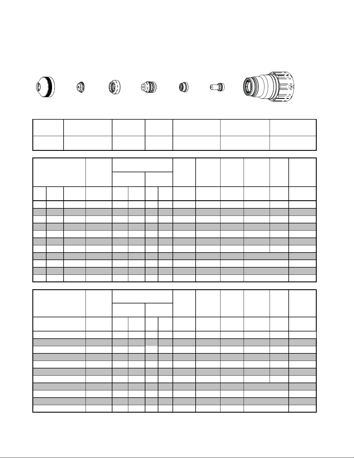
Torch Parts Selection
The application will determine which torch parts must be used. Refer to the cut charts for the proper torch parts to
install for a selected application.
CAUTION
Do not interchange parts. Make sure all torch parts correspond with the
plasma and shield gases in use for the application.
Pre-Setting Power Supply Controls
Set the Power Supply controls prior to operating the system as described in the power supply Operating Manual.
Refer to the cutting charts for the proper cutting parameters for the application.
Recommended Cutting Speeds
Cutting speed depends on material and thickness. The following factors may affect system performance:
• Torch parts wear; gas quality and mass flow / pressure; operator experience; torch standoff height; proper
work cable connection; alloy contents of material; cutting table capabilities & accuracy.
NOTE
This information represents realistic expectations using recommended
practices and well-maintained systems. Actual speeds may vary from
those shown in the charts depending on the alloy content of the selected
material. Voltage ratings may vary depending on the CNC, cutting table,
or height controller.
For complete cutting speed chart data refer to the following pages.
Consumables Notes
Always assemble the consumable parts properly. Improper assembly may damage the parts or the torch head.
Ensure that parts are seated together correctly.
Always check the shield gas distributor for charring when changing parts. Do not use the distributor if it is charred.
Replace the shield gas distributor regularly to ensure proper performance.
Operational Notes
Always purge the torch after changing consumables or if the power supply has been shut off. The power supply's
built-in purge function may not be enough to properly purge the torch. Manually flow gas with the 'Test Cut Flow' and
'Test Pre-Flow' functions to help remove any remaining coolant from the lines.
Slightly increasing the preflow pressure may increase piercing ability on thicker materials. However, increasing the
preflow pressure too much may affect plasma starting reliability (misfiring).
Decreasing preflow pressure may improve piloting. Preflow pressure can be reduced without affecting cut performance as long as the pilot arc still transfers to the plate well. Decreasing preflow pressure too much will affect the
ability to transfer the arc to the plate and may cause damage to the tip.
Notes on Chart Measurements
Pressure measurements in the charts are in psi(g), not psi(a). 0 psi(g) = 14.7 psi(a) (1 atmosphere).
Ball settings are at the center of the gauge ball.
Manual 0-4831 Rev. AH 8-1 TORCH DATA for AutoCut O
2
Page 2
Ohmic Sensing
Ohmic sensing is not recommended with water shield. Water on the plate interferes electrically with the ohmic
sensing circuit.
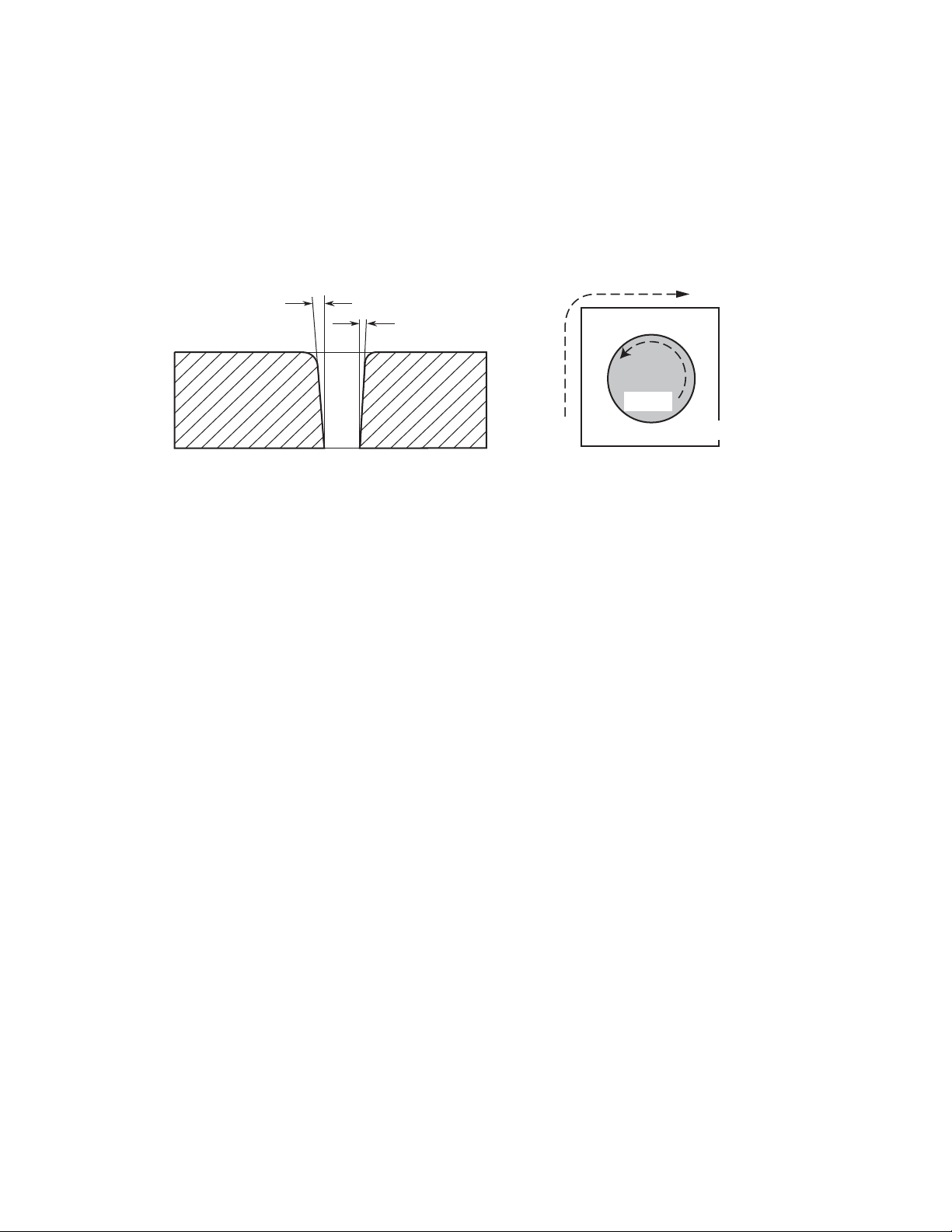
Direction of Cut
The plasma gas stream swirls as it leaves the torch to maintain a stable arc column. This swirl effect results in one
side of a cut being more square than the other. Viewed along the direction of travel, the right side of the cut is more
square than the left.
Left Side
Cut Angle
Right Side
Cut Angle
A-00512
Clockwise
Scrap
Counter-
Clockwise
Scrap
Workpiece
Art # A-04182
Side Characteristics Of Cut
To make a square - edged cut along an inside diameter of a circle, move the torch counterclockwise around the circle.
To keep the square edge along an outside diameter cut, move the torch in a clockwise direction.
Underwater Cutting
Cutting on a water table either underwater or with the water touching the plate or with a water muffler system is not
recommended. If a water table is used the water level must be a minimum of 4 inches / 100 mm from the bottom of the
plate. Failure to follow this recommendation could result in poor cut quality and short consumable parts life.
TORCH DATA for AutoCut O
2
8-2 Manual 0-4831 Rev. AH
Page 3
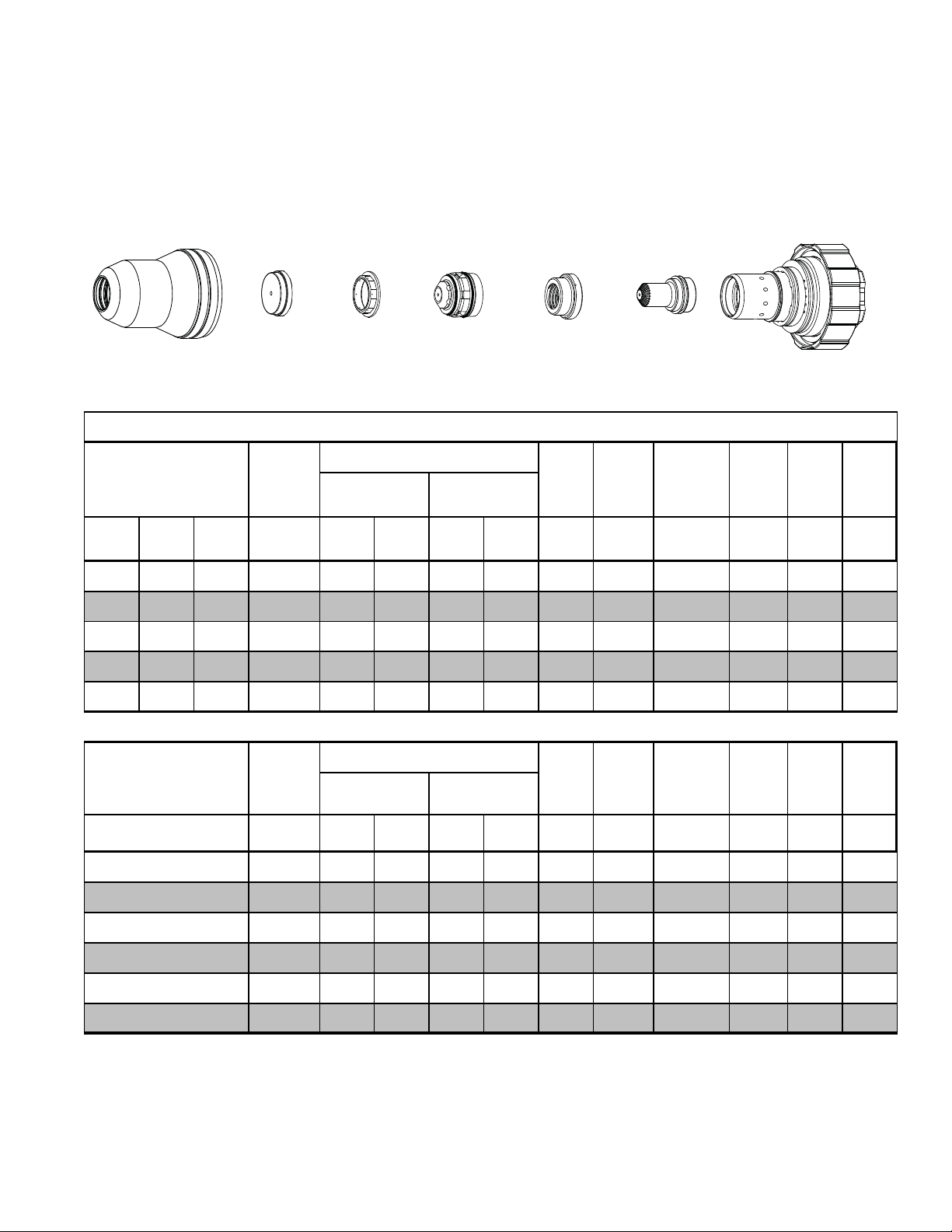
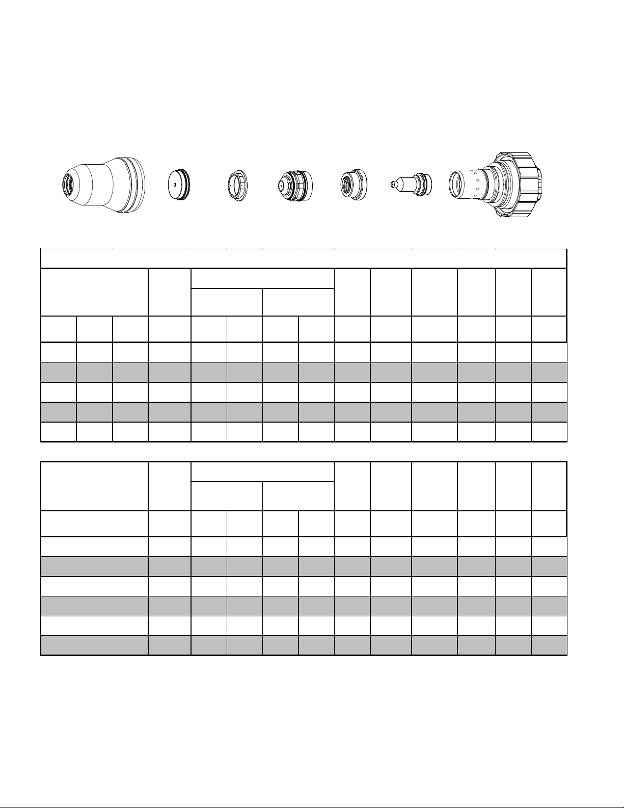
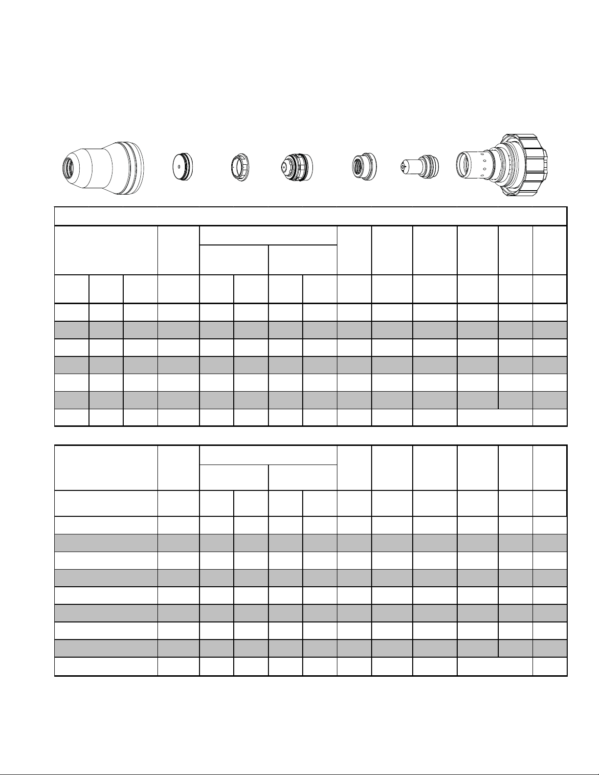
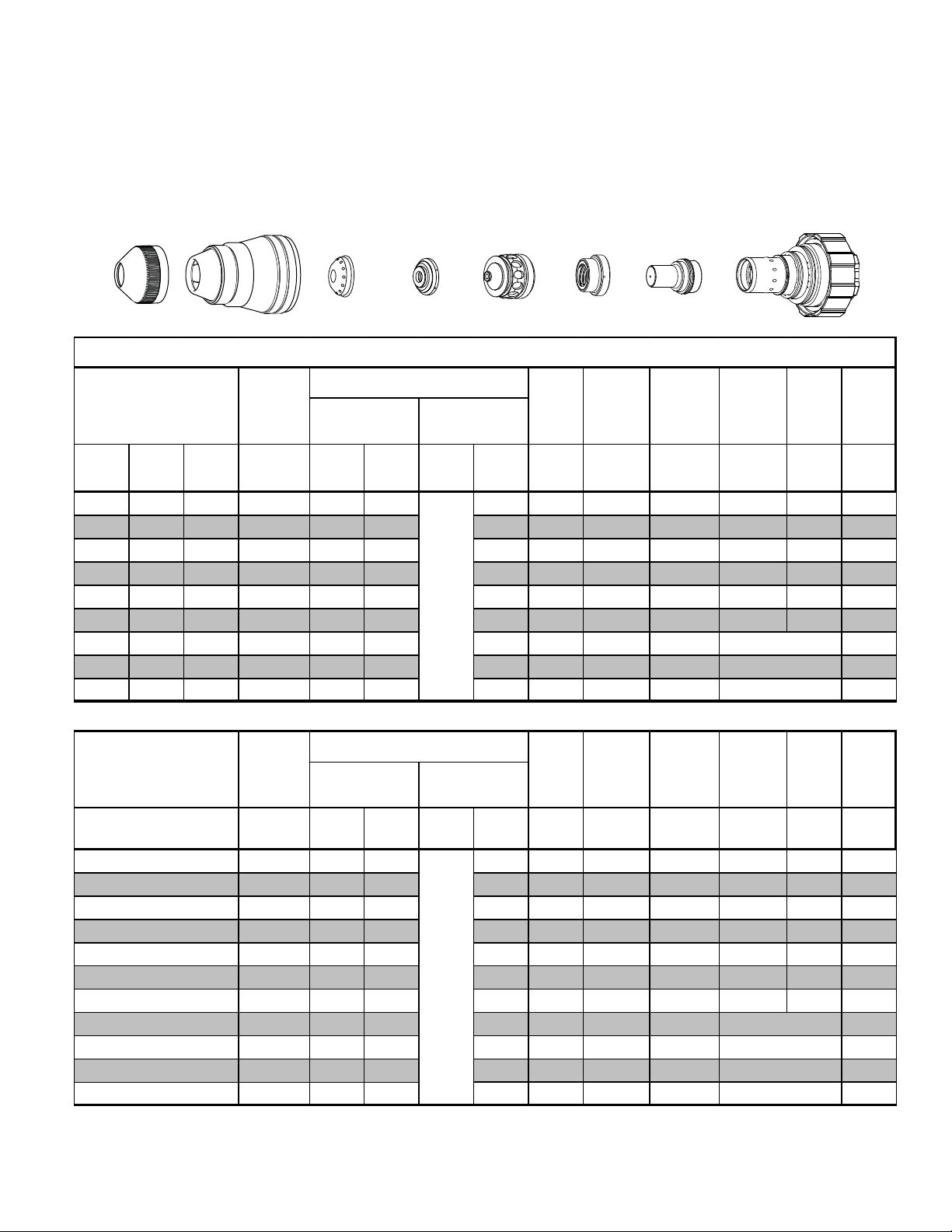
55A
Mild Steel
Air Plasma / Air Shield
Shield Cup
35-1016
Shield Cap
35-1025
35-1272
Tip
35-1051
Plasma Gas DistributorShield Gas Distributor
35-1041
Electrode
35-1069
Cartridge
35-1020
Art # A-07288
55A Mild Steel (Air/Air)
Material
Thickness
(ga) (in) inch psi Ball psi Ball psi Volts
21 0.033 70 58 90 32 90 165 0.188 500 0.200 0.1 0.079
16 0.060 70 58 90 32 90 165 0.188 300 0.200 0.1 0.086
10 0.135 70 58 90 84 90 168 0.188 190 0.200 0.2 0.079
3/16 0.188 70 58 90 84 90 168 0.188 130 0.250 0.3 0.089
Pre Flow
Pressure
(Air)
Cut Flow Rates / Pressures
Plasma (Air) Shield (A ir)
Arc
Voltage
Torch
Working
Height
(in)
±0.005
Travel
Speed
(ipm) (in) (sec) (in)
Initial
Piercing
Height
Pierce
Delay
Kerf
Width
@ Rec.
Speed
1/4 0.250 70 58 90 84 90 171 0.188 95 0.250 0.3 0.090
Material
Thickness
(mm)
1
2
3
4
5
6
Pre Flow
Pressure
(Air)
bar Ball bar Ball bar Volts
4.8 58 6.2 32 6.2 165 4.8 11500 5.1 0.1 2.0
4.8 58 6.2 32 6.2 166 4.8 6920 5.1 0.1 2.1
4.8 58 6.2 84 6.2 167 4.8 5460 5.1 0.2 2.0
4.8 58 6.2 84 6.2 168 4.8 4180 5.6 0.2 2.1
4.8 58 6.2 84 6.2 168 4.8 3180 6.4 0.3 2.3
4.8 58 6.2 84 6.2 170 4.8 2610 6.4 0.3 2.3
Cut Flow Rates / Pressures
Plasma (Air) Shield (A ir)
Arc
Voltage
Torch
Working
Height
(mm)
±0.1
Travel
Speed
(mm/min) (mm) (sec) (mm)
Initial
Piercing
Height
Pierce
Delay
Kerf
Width
@ Rec.
Speed
Manual 0-4831 Rev. AH 8-5 TORCH DATA for AutoCut O
2
Page 4
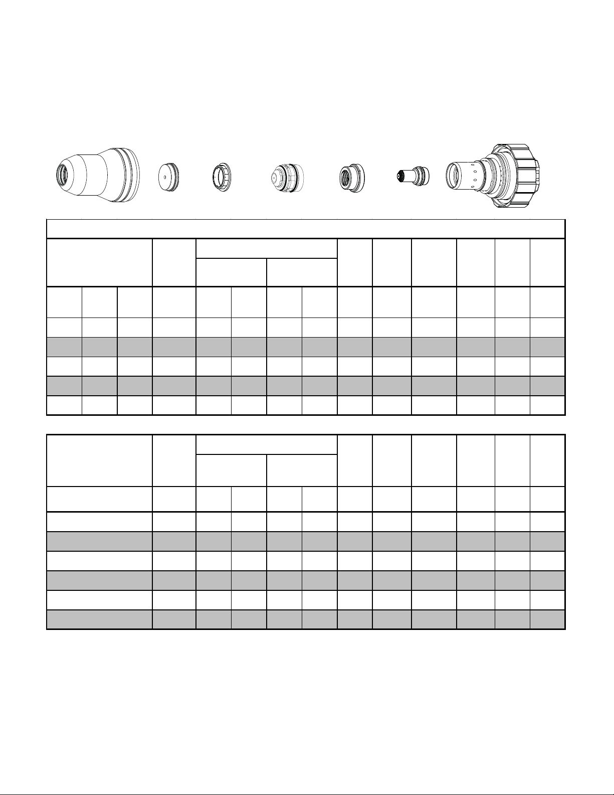
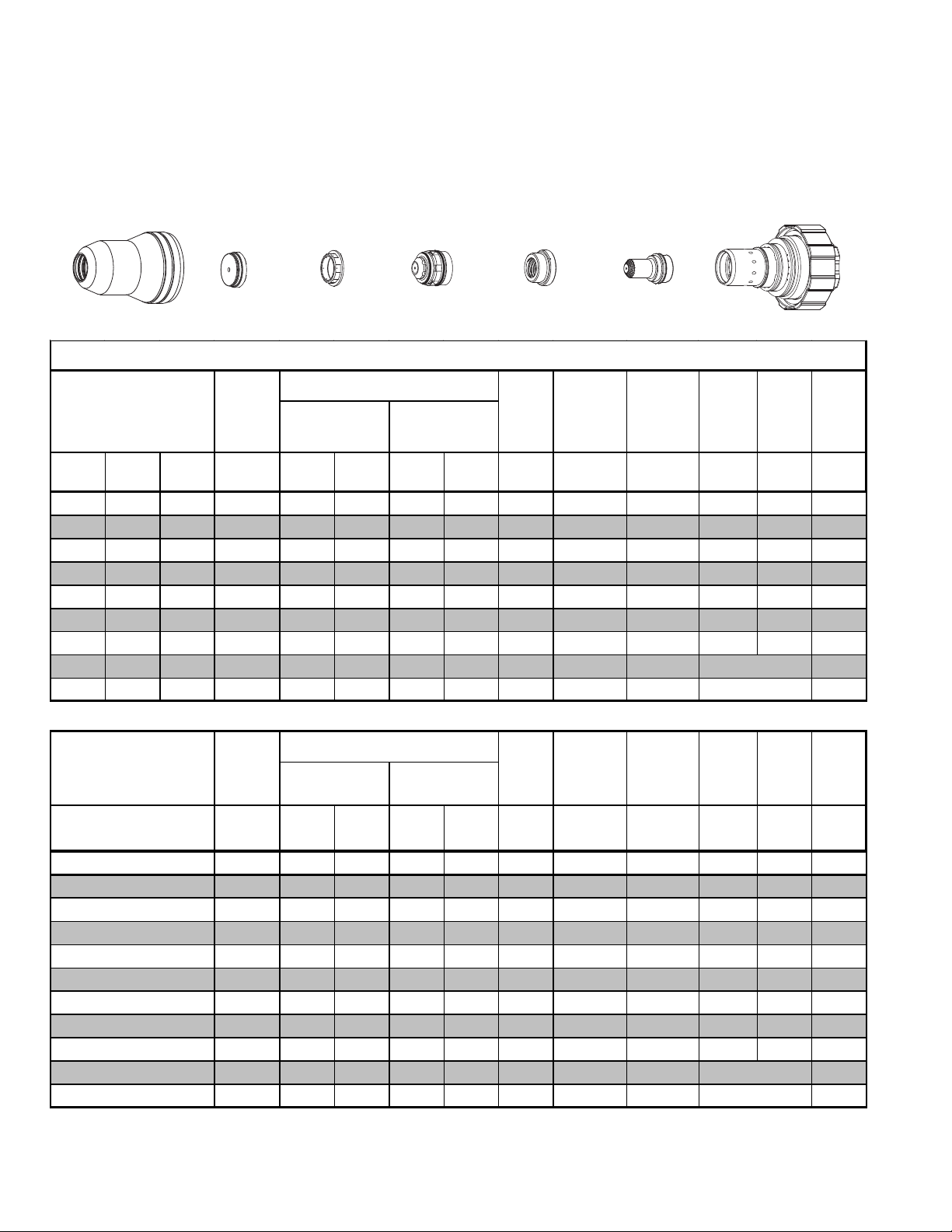
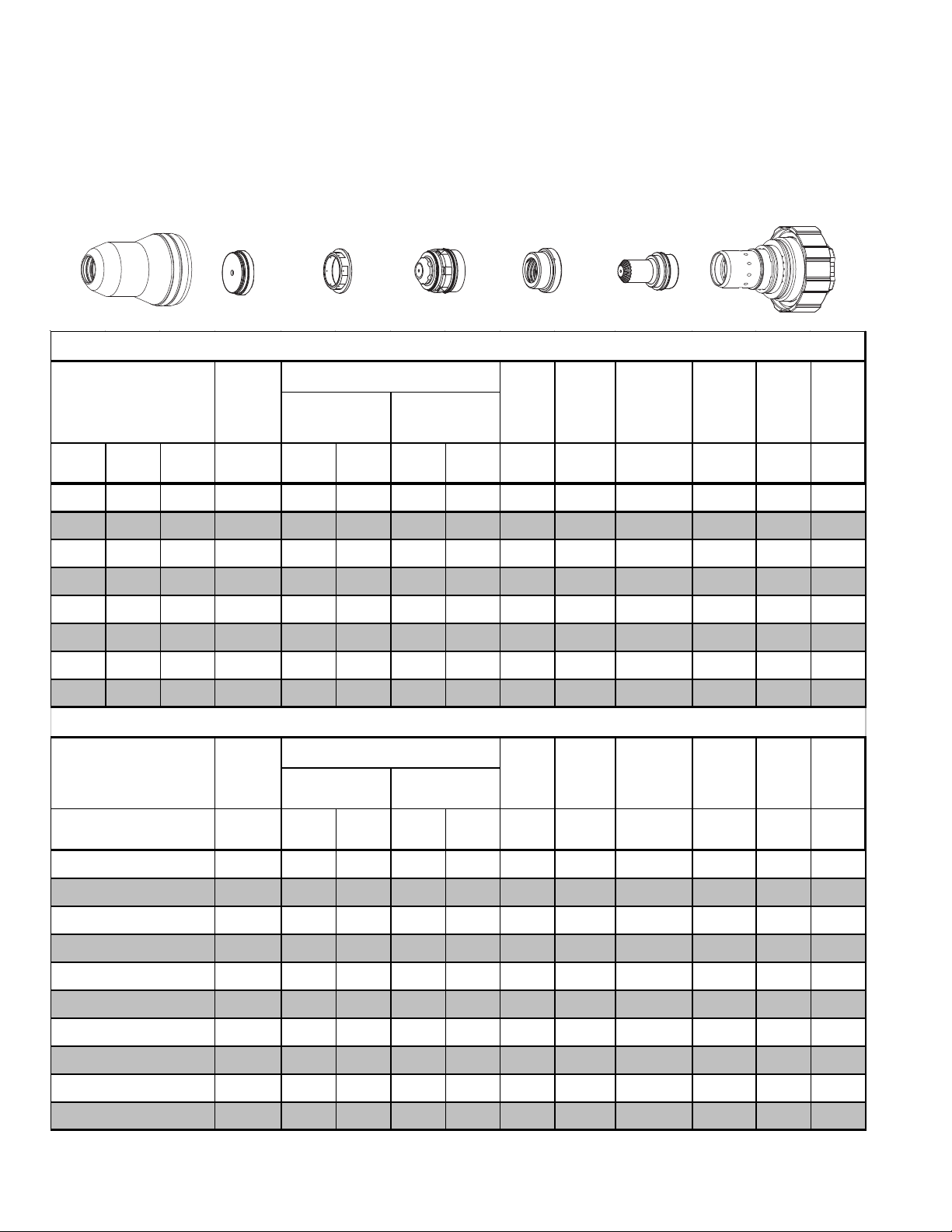
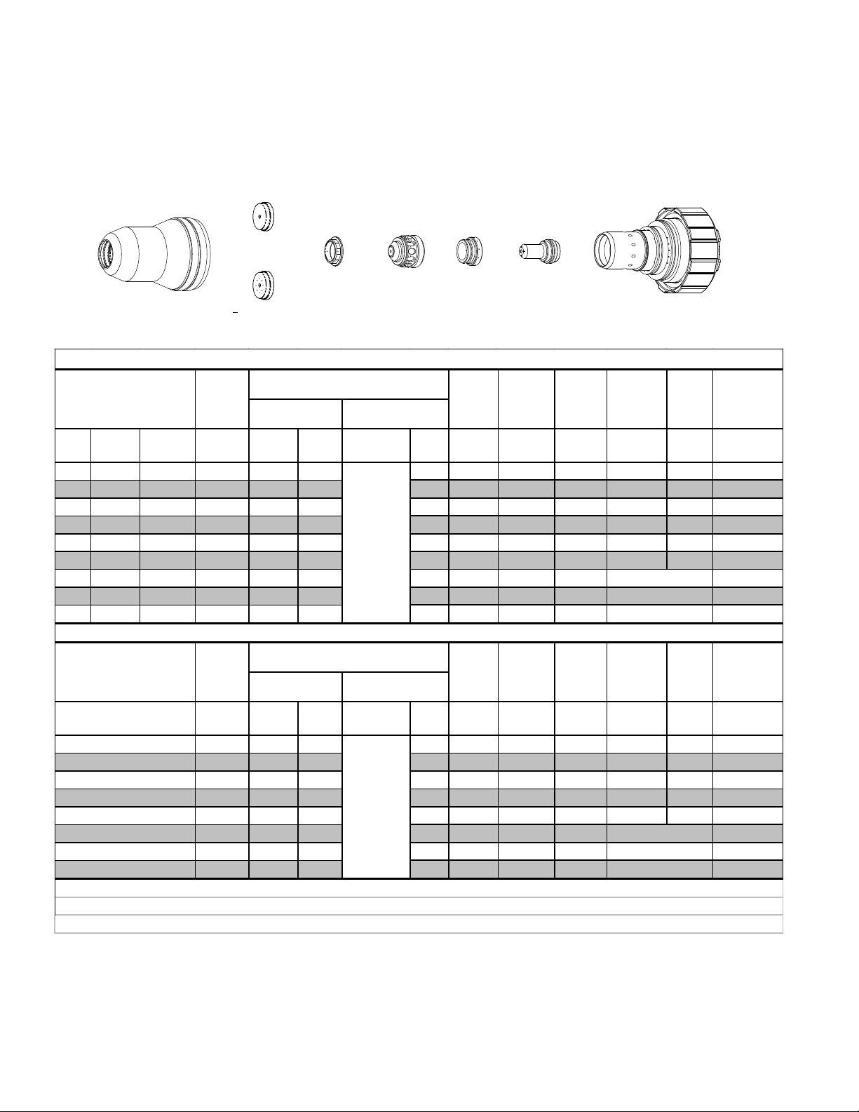
55A
Mild Steel
Plasma / Air Shield
O
2
Shield Cup
35-1016
Material
Thickness
(ga) (in) inch psi Ball psi Ball psi Volts
Shield Cap
35-1025
Pre Flow
Pressure
Shield Gas Distributor
(Air)
35-1272
Cut Flow Rates / Pr essures
Plasma (O
Tip
35-1051
Plasma Gas Distributor
55A Mild Steel (O
Shield (Air)
)
2
35-1041
/Air)
2
Arc
Voltage
Electrode
35-1069
Torch
Working
Height
(in)
±0.005
Cartridge
35-1020
Art # A-07289
Travel
Speed
(ipm) (in) (sec) (in)
Initial
Piercing
Height
Pierce
Delay
Kerf
Width
@ Rec.
Speed
21 0.033 90 65 120 26 90 168 0.125 600 0.200 0.0 0.073
16 0.060 90 65 120 26 90 168 0.125 400 0.200 0.0 0.071
10 0.135 90 65 120 26 90 142 0.125 180 0.200 0.2 0.083
3/16 0.188 90 65 120 26 90 145 0.125 120 0.200 0.2 0.081
1/4 0.250 90 65 120 26 90 147 0.125 85 0.200 0.3 0.086
Material
Thickness
(mm)
1
2
3
4
5
6
Pre Flow
Pressure
(Air)
bar Ball bar Ball bar Volts
Cut Flow Rates / Pr essures
Plasma (O
) Shield (Air)
2
Arc
Voltage
Torch
Working
Height
(mm)
±0.1
Travel
Speed
(mm/min) (mm) (sec) (mm)
Initial
Piercing
Height
Pierce
Delay
6.2 65 8.3 26 6.2 168 3.2 140 40 5.1 0.0 1.8
6.2 65 8.3 26 6.2 162 3.2 8760 5.1 0.0 1.9
6.2 65 8.3 26 6.2 148 3.2 5830 5.1 0.2 2.0
6.2 65 8.3 26 6.2 143 3.2 3930 5.1 0.2 2.1
6.2 65 8.3 26 6.2 145 3.2 2920 5.1 0.2 2.1
6.2 65 8.3 26 6.2 147 3.2 2360 5.1 0.3 2.2
Kerf
Width
@ Rec.
Speed
TORCH DATA for AutoCut O
2
8-6 Manual 0-4831 Rev. AH
Page 5
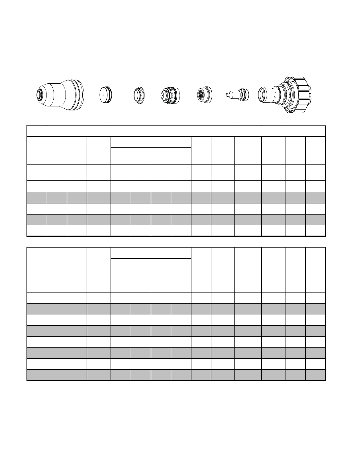
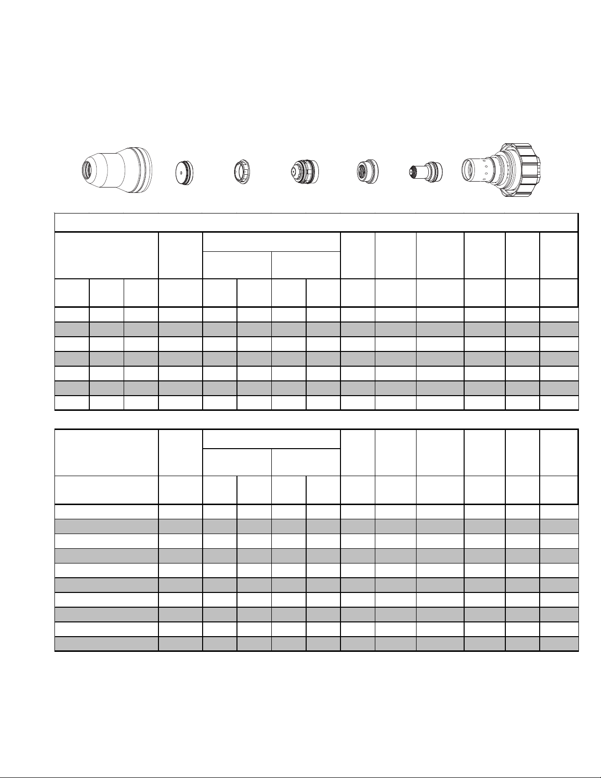
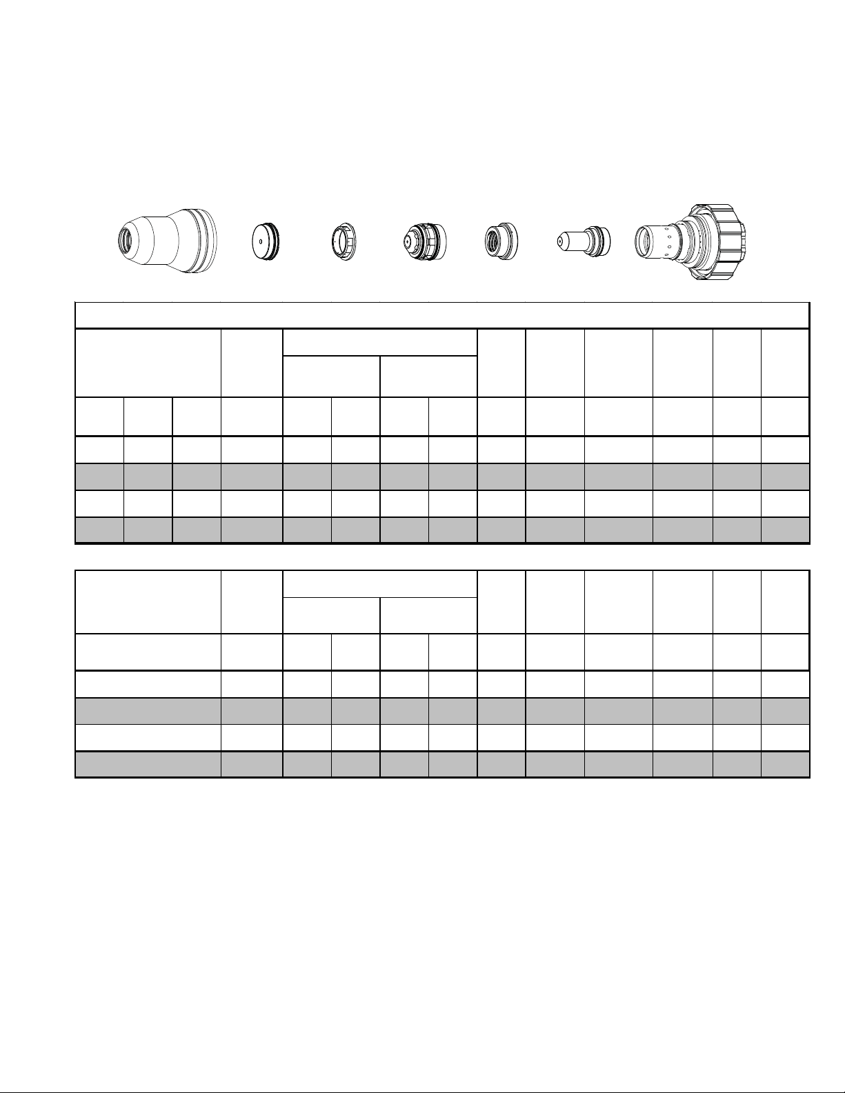
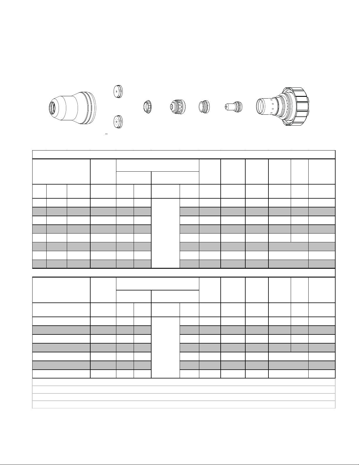
55A
Stainless Steel
Air Plasma / Air Shield
Shield Cup
35-1016
Shield Cap
35-1034
Shield Gas Distributor
35-1272
Tip
35-1060
Plasma Gas Distributor
35-1041
Electrode
35-1078
Cartridge
35-1020
Art # A-07294
55A Stainless Steel (Air/Air)
Material
Thickness
(ga) (in) inch psi Ball ps i Ball psi Volts
Pre Flow
Pressure
(Air)
Cut Flow Rates / Pressures
Plasma (A ir) Shield (Air)
Arc
Voltage
Torch
Working
Height
(in)
±0.005
Travel
Speed
(ipm) (in) (sec) (in)
Initial
Piercing
Height
Pierce
Delay
Kerf
Width
@ Rec.
Speed
21 0.034 90 45 90 55 90 117 0.125 600 0.200 0.0 0.067
16 0.063 90 45 90 55 90 117 0.150 350 0.200 0.0 0.068
10 0.141 90 45 90 55 90 117 0.150 100 0.200 0.1 0.086
3/16 0.188 90 45 90 55 90 123 0.150 60 0.200 0.1 0.086
1/4 0.250 90 45 90 55 90 123 0.150 40 0.200 0.2 0.088
Material
Thickness
(mm)
0.8
1
1.5
2
3
4
5
6
Pre Flow
Pressure
(Air)
bar Ball bar Bal l bar Volts
Cut Flow Rates / Pressures
Plasma (A ir) Shield (Air)
Arc
Voltage
Torch
Working
Height
(mm)
±0.1
Travel
Speed
(mm/min) (mm) (sec) (mm)
Initial
Piercing
Height
Pierce
Delay
6.2 45 6.2 55 6.2 117 3.2 15240 5.1 0.0 1.7
6.2 45 6.2 55 6.2 117 3.3 14060 5.1 0.0 1.7
6.2 45 6.2 55 6.2 117 3.7 9750 5.1 0.0 1.7
6.2 45 6.2 55 6.2 117 3.8 7610 5.1 0.0 1.8
6.2 45 6.2 55 6.2 117 3.8 4400 5.1 0.1 2.1
6.2 45 6.2 55 6.2 119 3.8 2180 5.1 0.1 2.2
6.2 45 6.2 55 6.2 123 3.8 1450 5.1 0.1 2.2
6.2 45 6.2 55 6.2 123 3.8 1130 5.1 0.2 2.2
Kerf
Width
@ Rec.
Speed
Manual 0-4831 Rev. AH 8-7 TORCH DATA for AutoCut O
2
Page 6
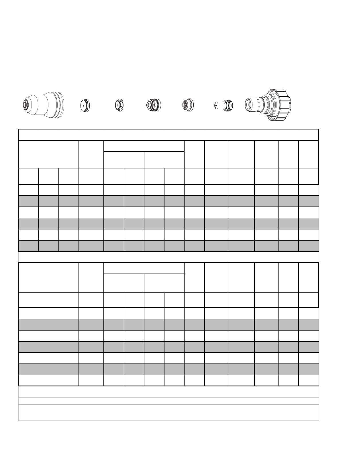
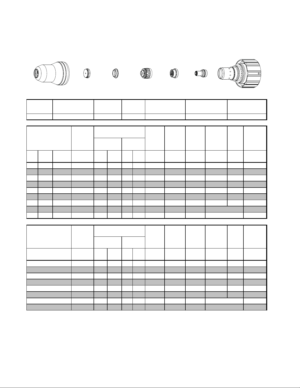
55A
Aluminum
Air Plasma / Air Shield
Shield Cup
35-1016
Shield Cap
35-1034
Shield Gas Distributor
35-1272
Tip
35-1060 35-107835-1041
Plasma Gas Distributor
Electrode
Cartridge
35-1020
Art # A-07298
55A Aluminum (Air/Air)
Material
Thickness
(ga) (in) inch psi Ball psi Ball psi Volts
Pre Flow
Pressure
(Air)
Cut Flow Rates / Pressures
Plasma (A ir)
Shield ( Air)
Arc
Voltage
Torch
Working
Height
(in)
±0.005
Travel
Speed
(ipm) (in) (s ec) (in)
Initial
Piercing
Height
Pierce
Delay
Kerf
Width
@ Rec.
Speed
23 0.031 90 45 90 55 90 120 0.100 600 0.150 0.0 0.066
16 0.064 90 45 90 55 90 120 0.100 400 0.200 0.0 0.070
11 0.125 90 45 90 55 90 125 0.150 140 0.200 0.0 0.084
3/16 0.188 90 45 90 55 90 125 0.150 100 0.200 0.0 0.084
1/4 0.250 90 45 90 55 90 125 0.150 50 0.200 0.1 0.089
Material
Thickness
(mm)
1
2
3
4
5
6
Pre Flow
Pressure
(Air)
bar Ball bar Ball bar Volts
Cut Flow Rates / Pressures
Plasma (A ir) Shield (Air)
Arc
Voltage
Torch
Working
Height
(mm)
±0.1
Travel
Speed
(mm/min) (mm) (sec) (mm)
Initial
Piercing
Height
Pierce
Delay
6.2 45 6.2 55 6.2 120 2.5 13950 4.1 0.0 1.7
6.2 45 6.2 55 6.2 121 2.8 8790 5.1 0.0 1.9
6.2 45 6.2 55 6.2 124 3.5 5130 5.1 0.0 2.0
6.2 45 6.2 55 6.2 125 3.8 3130 5.1 0.0 2.1
6.2 45 6.2 55 6.2 125 3.8 2360 5.1 0.0 2.2
6.2 45 6.2 55 6.2 125 3.8 1550 5.1 0.1 2.2
Kerf
Width
@ Rec.
Speed
TORCH DATA for AutoCut O
2
8-8 Manual 0-4831 Rev. AH
Page 7

100A
Mild Steel
Air Plasma / Air Shield
Shield Cup
35-1016
Shield Cap
35-1027
Shield Gas Distributor
35-1272
Tip
35-1053
Plasma Gas Distributor
35-1041
Electrode
35-1071
Cartridge
35-1020
Art # A-07290
100A Mild Ste el (Air/Air)
Material
Thickness
(ga) (in) inch psi Ball ps i Ball psi Volts
Pre Flow
Pressure
(Air)
Cut Flow Rates / Pressures
Plasma (A ir) Shield (Air)
Arc
Voltage
Torch
Working
Height
(in)
±0.005
Travel
Speed
(ipm) (in) (sec) (in)
Initial
Piercing
Height
Pierce
Delay
Kerf
Width
@ Rec.
Speed
16 0.060 74 58 90 90 90 150 0.110 600 0.250 0.1 0.072
10 0.135 74 58 90 90 90 150 0.110 300 0.250 0.2 0.065
3/16 0.188 74 58 90 90 90 150 0.110 210 0.250 0.3 0.073
1/4 0.250 74 58 90 90 90 155 0.120 150 0.300 0.3 0.078
3/8 0.375 74 58 90 90 90 155 0.130 85 0.300 0.3 0.091
1/2 0.500 74 58 90 43 90 157 0.140 75 0.300 0.3 0.095
5/8 0.625 74 58 90 43 90 165 0.140 55 0.350 0.5 0.099
3/4 0.750 74 58 90 43 90 168 0.150 30 0.350 0.6 0.120
1 1.000 74 58 90 43 90 180 0.200 20 0.112
Edge Start
Material
Thickness
Bold type
Cut Flow Rates / Pressures
Plasma (A ir) Shield (Air)
(mm)
2
3
4
5
6
8
10
12
15
20
25
Pre Flow
Pressure
(Air)
bar Ball bar Ball bar Volts
5.1 58 6.2 90 6.2 150 2.8 13340 6.4 0.1 1.8
5.1 58 6.2 90 6.2 150 2.8 9340 6.4 0.2 1.7
5.1 58 6.2 90 6.2 150 2.8 6650 6.4 0.2 1.7
5.1 58 6.2 90 6.2 151 2.8 5120 6.5 0.3 1.9
5.1 58 6.2 90 6.2 154 3.0 4150 7.3 0.3 2.0
5.1 58 6.2 90 6.2 155 3.2 2950 7.6 0.3 2.2
5.1 58 6.2 90 6.2 155 3.3 2120 7.6 0.3 2.3
5.1 58 6.2 45 6.2 157 3.5 1960 7.6 0.3 2.4
5.1 58 6.2 45 6.2 163 3.6 1540 8.5 0.4 2.5
5.1 58 6.2 45 6.2 170 4.0 720 9.5 0.6 3.0
5.1 58 6.2 45 6.2 179 5.0 520 2.9
indicates maximum piercing parameters.
Bold italic
Arc
Voltage
indic at es edge s tarts only.
Torch
Working
Height
(mm)
±0.1
Travel
Speed
(mm/min) (mm) (sec) (mm)
Initial
Piercing
Height
Pierce
Delay
Edge Start
Manual 0-4831 Rev. AH 8-9 TORCH DATA for AutoCut O
Kerf
Width
@ Rec.
Speed
2
Page 8
100A
Mild Steel
Plasma / Air Shield
O
2
Shield Cup
35-1016
Material
Thickness
(ga) (in) inch psi Ball psi Ball psi Volts
Shield Cap
35-1027
Pre Flow
Pressure
(Air)
Shield Gas Distributor
35-1272
35-1053
100A Mild Ste e l (O
Cut Flow Rates / Pressures
Plasma (O
) Shield (Air)
2
Tip
Plasma Gas Distributor
35-1041
/Air)
2
Arc
Voltage
Torch
Working
Height
(in)
±0.005
Electrode
35-1071
Travel
Speed
(ipm) (in) (sec) (in)
Cartridge
35-1020
Art # A-07291
Initial
Piercing
Height
Pierce
Delay
Kerf
Width
@ Rec.
Speed
16 0.060 74 56 120 90 90 127 0.110 500 0.250 0.1 0.071
10 0.135 74 56 120 90 90 134 0.110 240 0.250 0.2 0.081
3/16 0.188 74 56 120 90 90 128 0.120 185 0.250 0.3 0.073
1/4 0.250 74 56 120 90 90 130 0.120 130 0.300 0.3 0.095
3/8 0.375 74 56 120 90 90 138 0.130 80 0.300 0.3 0.113
1/2 0.500 74 56 120 90 90 138 0.140 57 0.300 0.3 0.113
5/8 0.625 74 56 120 90 90 144 0.140 45 0.350 0.5 0.111
3/4 0.750 74 56 120 90 90 150 0.150 25 0.138
1 1.000 74 56 120 90 90 164 0.200 10 0.140
Edge Start
Edge Start
Material
Thickness
(m m)
2
3
4
5
6
8
10
12
15
20 Edge Start
Bold type
indic at es m ax i m um piercing paramet ers.
TORCH DATA for AutoCut O
Pre Flow
Pressure
(Air)
bar Ball bar Ball bar Volts
Cut Flow Rates / Pressures
Plasma (O
) Shield (Air)
2
Arc
Voltage
Torch
Working
Height
(m m)
±0.1
Travel
Speed
(m m/min) (mm) (sec) (mm)
Initial
Piercing
Height
Pierce
Delay
5.1 56 8.3 90 6.2 129 2.8 11050 6.4 0.1 1.9
5.1 56 8.3 90 6.2 132 2.8 7580 6.4 0.2 2.0
5.1 56 8.3 90 6.2 131 2.9 5500 6.4 0.2 2.0
5.1 56 8.3 90 6.2 128 3.1 4500 6.5 0.3 1.9
5.1 56 8.3 90 6.2 130 3.1 3610 7.3 0.3 2.3
5.1 56 8.3 90 6.2 134 3.2 2640 7.6 0.3 2.7
5.1 56 8.3 90 6.2 138 3.3 1950 7.6 0.3 2.9
5.1 56 8.3 90 6.2 138 3.5 1580 7.6 0.3 2.9
5.1 56 8.3 90 6.2 142 3.6 1230 8.5 0.4 2.8
5.1 56 8.3 90 6.2 152 4.0 580 3.5
5.1 56 8.3 90 6.2 163 5.0 280 3.6
Bold italic
2
indicat es edge s t art s only.
8-10 Manual 0-4831 Rev. AH
Edge Start25
Kerf
Width
@ Rec.
Speed
Page 9
100A
Stainless Steel
Air Plasma / Air Shield
Shield Cup
35-1016
Shield Cap
35-1027
Shield Gas Distributor
35-1272
Tip
35-1053
Plasma Gas Distributor
35-1041
Electrode
35-1071
Cartridge
35-1020
Art # A-07295
100A Stainless Ste e l (Air/Air)
Material
Thickness
(ga) (in) inch psi Ball psi Ball psi Volts
Pre Flow
Pressure
(Air)
Cut Flow Rates / Pressures
Plasma (A ir) Shield (Air)
Arc
Voltage
Torch
Working
Height
(in)
±0.005
Travel
Speed
(ipm) (in) (sec) (in)
Initial
Piercing
Height
Pierce
Delay
Kerf
Width
@ Rec.
Speed
16 0.063 90 58 90 75 90 145 0.080 500 0.200 0.0 0.099
10 0.141 90 58 90 75 90 150 0.100 225 0.325 0.0 0.102
3/16 0.188 90 58 90 75 90 153 0.140 175 0.325 0.1 0.105
1/4 0.250 90 58 90 75 90 157 0.140 100 0.325 0.1 0.105
3/8 0.375 90 58 90 75 90 158 0.140 65 0.325 0.2 0.110
1/2 0.500 90 58 90 75 90 165 0.160 45 0.325 0.4 0.112
5/8 0.625 90 58 90 75 90 168 0.160 35 0.350 1.0 0.114
Material
Thickness
Bold type
Cut Flow Rates / Pressures
Plasma (A ir) Shield (Air)
(mm)
1.5
2
3
4
5
6
8
10
12
15
Pre Flow
Pressure
(Air)
bar Ball bar Ball bar Volts
6.2 58 6.2 75 6.2 145 2.0 12700 5.1 0.0 2.4
6.2 58 6.2 75 6.2 146 2.1 11290 5.7 0.0 2.5
6.2 58 6.2 75 6.2 149 2.0 6330 8.3 0.0 2.6
6.2 58 6.2 75 6.2 151 3.6 5270 8.3 0.1 2.7
6.2 58 6.2 75 6.2 154 3.6 4170 8.3 0.1 2.7
6.2 58 6.2 75 6.2 156 3.6 3020 8.3 0.1 2.7
6.2 58 6.2 75 6.2 158 3.6 2080 8.3 0.2 2.7
6.2 58 6.2 75 6.2 159 3.6 1580 8.3 0.2 2.8
6.2 58 6.2 75 6.2 163 4.0 1260 8.3 0.4 2.8
6.2 58 6.2 75 6.2 167 4.1 960 8.7 0.8 2.9
indicates maximum piercing parameters.
Arc
Voltage
Torch
Working
Height
(mm)
±0.1
Travel
Speed
(m m/min) (mm) (sec) (mm)
Initial
Piercing
Height
Pierce
Delay
Kerf
Width
@ Rec.
Speed
Manual 0-4831 Rev. AH 8-11 TORCH DATA for AutoCut O
2
Page 10
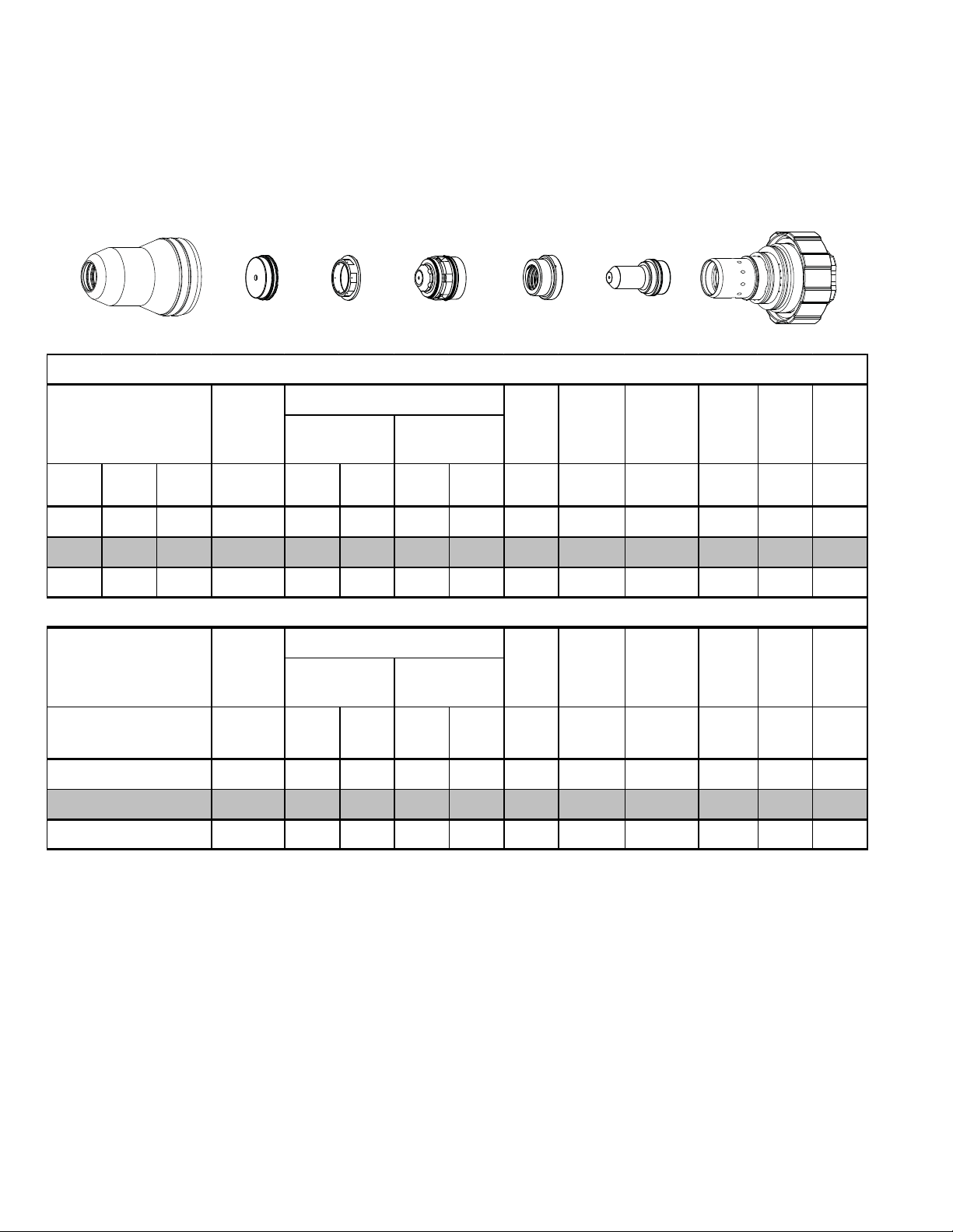
100A
Stainless Steel
H35 Plasma / N
Shield Cup
35-1016
Shield
2
Shield Cap
35-1034
Shield Gas Distributor
35-1272
Tip
35-1062
Plasma Gas Distributor
35-1041
100A Stainless Steel (H35/N2)
Material
Thickness
(ga) (in) inch psi Ball ps i Ball ps i Volts
Pre F low
Pressure
)
(N
2
Cut Flow Rates / Pr essures
Plasma (H35)
Shield (N
2
)
Arc
Voltage
3/8 0.375 80 65 120 59 120 148 0.130 50 0.250 0.3 0.090
1/2 0.500 80 65 120 81 120 158 0.130 37 0.250 0.5 0.100
5/8 0.625 80 65 120 43 120 172 0.140 26 0.250 0.6 0.115
Torch
Working
Height
(in)
±0.005
Electrode
35-1080
Travel
Speed
(ipm) (in) (sec) (in)
Cartridge
35-1020
Art # A-07296
Initial
Piercing
Height
Pierce
Delay
Kerf
Width
@ Rec.
Speed
Material
Thickness
(mm)
10
12
15
Pre F low
Pressure
(N
)
2
bar Ball b ar Ball ba r Volts
Cut Flow Rates / Pr essures
Plasma (H35) Shield (N
2
)
Arc
Voltage
Torch
Working
Height
(mm)
±0.1
Travel
Speed
(mm/min) (mm) (sec) (mm)
Initial
Piercing
Height
Pierce
Delay
5.5 65 8.3 59 8.2 149 3.3 1220 6.4 0.3 2.3
5.5 65 8.3 81 8.2 156 3.3 1010 6.4 0.5 2.5
5.5 65 8.3 43 8.2 168 3.5 740 6.4 0.6 2.8
Kerf
Width
@ Rec.
Speed
TORCH DATA for AutoCut O
2
8-12 Manual 0-4831 Rev. AH
Page 11
100A
Stainless Steel
Plasma / H2O Shield
N
2
Shield Cup
35-1016
Shield Cap
35-1034
Shield Gas Distributor
35-1272
100A Stainless Steel (N2/H2O)
Tip
35-1053
Plasma Gas Distributor
35-1041
Electrode
35-1089
Cartridge
35-1020
Art # A-07297
Material
Thickness
(ga) (in) inch psi Ball* psi Ball* psi Volts
Pre Flow
Pressure
(N
)
2
Cut Flow Rates / Pressures
Plasma (N
) Shield (H2O)
2
Arc
Voltage
Torch
Working
Height
(in)
±0.005
Travel
Speed
(ipm) (in) (sec) (in)
Initial
Piercing
Height
Pierce
Delay
Kerf
Width
@ Rec.
Speed
10 0.141 80 60 120 5 55 156 0.125 160 0.200 0.000 0.074
3/16 0.188 80 60 120 5 55 158 0.125 100 0.250 0.300 0.080
1/4 0.250 80 60 120 5 55 165 0.125 60 0.250 0.300 0.086
3/8 0.375 80 60 120 5 55 173 0.125 50 0.250 0.300 0.087
1/2 0.500 80 60 120 5 55 179 0.130 35 0.300 0.500 0.100
5/8 0.625 80 60 120 5 55 181 0.140 30 0.300 0.600 0.110
3/4 0.750 80 60 120 5 55 185 0.150 25 0.120
Material
Thickness
(mm)
3
Pre Flow
Pressure
)
(N
2
bar Ball* bar Ball* bar Volts
5.5 60 8.3 5 3.8 155 3.2 4810 4.5 0 1.8
Cut Flow Rates / Pressures
Plasma (N
)
2
Shield ( H2O)
Arc
Voltage
Torch
Working
Height
(mm)
±0.1
Travel
Speed
(mm/min) (mm) (sec) (mm)
Edge Start
Initial
Piercing
Height
Pierce
Delay
Kerf
Width
@ Rec.
Speed
4
5
6
8
10
12
15
20
5.5 60 8.3 5 3.8 157 3.2 3530 5.5 0.1 1.9
5.5 60 8.3 5 3.8 159 3.2 2400 6.4 0.3 2.1
5.5 60 8.3 5 3.8 163 3.2 1750 6.4 0.3 2.2
5.5 60 8.3 5 3.8 169 3.2 1390 6.4 0.3 2.2
5.5 60 8.3 5 3.8 174 3.2 1210 6.5 0.3 2.3
5.5 60 8.3 5 3.8 178 3.3 970 7.3 0.5 2.5
5.5 60 8.3 5 3.8 180 3.5 800 7.6 0.6 2.7
5.5 60 8.3 5 3.8 186 3.9 600 3.0
Edge Start
* Bal l set t i ng for shiel d wat er is s et using cus tomer li ne pres sure of 55 psi / 3. 8 bar
Bold type
NOTE:
indicates maximum piercing parameters.
Ohmic height sens i ng is not rec om m ended wit h water s hi el d. Water on the plat e i nt erferes
Bold italic
indic at es edge s tarts only.
elec t ricall y wit h t he ohm ic sens ing sy stem.
Manual 0-4831 Rev. AH 8-13 TORCH DATA for AutoCut O
2
Page 12
100A
Aluminum
Air Plasma / Air Shield
Shield Cup
35-1016
Shield Cap
35-1027
Shield Gas Distributor
35-1272
Tip
35-1053
Plasma Gas Distributor
35-1041
Electrode
35-1071
Cartridge
35-1020
Art # A-07299
100A Aluminum (Air/Air)
Cut Flow Rates / Pressures
Plasma (Air) Shield (A ir)
Arc
Voltage
Material
Thickness
Pre Flow
Pressure
(Air)
(ga) (in) inch psi Ball psi Ball psi Volts
Torch
Working
Height
(in)
±0.005
Travel
Speed
Initial
Piercing
Height
Pierce
Delay
(ipm) (in) (sec) (in)
Kerf
Width
@ Rec.
Speed
16 .064 80 58 90 75 90 159 0.130 500 0.275 0.0 0.103
10 0.135 80 58 90 75 90 159 0.130 260 0.275 0.0 0.106
3/16 0.188 80 58 90 75 90 166 0.130 120 0.325 0.1 0.100
1/4 0.250 80 58 90 75 90 168 0.140 100 0.325 0.2 0.104
3/8 0.375 80 58 90 45 90 168 0.140 75 0.325 0.2 0.107
1/2 0.500 80 58 90 45 90 170 0.140 45 0.325 0.3 0.109
Material
Thickness
Bold type
5/8 0.625 80 58 90 45 90 176 0.140 35 0.325 0.4 0.112
3/4 0.750 80 58 90 45 90 180 0.180 35 0.350 0.9 0.121
Kerf
Width
@ Rec.
Speed
(mm)
(mm)
2
3
4
5
6
8
10
12
15
20
Pre Flow
Pressure
(Air)
bar Ball bar Ball bar Volts
Cut Flow Rates / Pressures
Plasma (Air) Shield (A ir)
Arc
Voltage
Torch
Working
Height
(mm)
±0.1
Travel
Speed
Initial
Piercing
Height
Pierce
Delay
(mm/min) (mm) (sec)
5.5 58 6.2 75 6.2 159 3.3 11430 7.0 0.0 2.6
5.5 58 6.2 75 6.2 159 3.3 8050 7.0 0.0 2.7
5.5 58 6.2 75 6.2 162 3.3 5100 7.5 0.0 2.6
5.5 58 6.2 75 6.2 166 3.3 2980 8.3 0.1 2.6
5.5 58 6.2 75 6.2 168 3.5 2650 8.3 0.2 2.6
5.5 58 6.2 45 6.2 168 3.6 2210 8.3 0.2 2.7
5.5 58 6.2 45 6.2 168 3.6 1790 8.3 0.2 2.7
5.5 58 6.2 45 6.2 170 3.6 1310 8.3 0.3 2.8
5.5 58 6.2 45 6.2 174 3.6 960 8.3 0.4 2.8
5.5 58 6.2 45 6.2 181 4.9 890 9.1 1.0 3.1
indicates maximum piercing parameters.
TORCH DATA for AutoCut O
2
8-14 Manual 0-4831 Rev. AH
Page 13
100A
Aluminum
H35 Plasma / N
Shield Cup
35-1016
Shield
2
Shield Cap
35-1034
Shield Gas Distributor
35-1272
Tip
35-1062
Plasma Gas Distributor
100A Aluminu m (H35/N2)
Material
Thickness
(ga) (in) inch psi Ball psi Ball psi Volts
Pre Flow
Pressure
(N
)
2
Cut Flow Rates / Pressures
Plasma (H35) Shield (N
)
2
3/8 0.375 80 68 120 51 120 153 0.188 60 0.350 0.1 0.100
1/2 0.500 80 68 120 51 120 158 0.188 40 0.350 0.4 0.110
5/8 0.625 80 68 120 51 120 160 0.188 30 0.350 0.5 0.113
3/4 0.750 80 68 120 51 120 174 0.250 20 0.350 0.6 0.130
35-1041
Arc
Voltage
Electrode
35-1080
Torch
Working
Height
(in)
±0.005
Cartridge
35-1020
Art # A-07300
Travel
Speed
(ipm) (in) (sec) (in)
Initial
Piercing
Height
Pierce
Delay
Kerf
Width
@ Rec.
Speed
Material
Thickness
Bold type
Cut Flow Rates / Pressures
Plasma (H35) Shield (N
(mm)
10
12
15
20
Pre Flow
Pressure
(N
)
2
bar Ball bar Ball bar Volts
5.5 68 8.3 51 8.3 154 4.8 1450 8.9 0.1 2.6
5.5 68 8.3 51 8.3 157 4.8 1130 8.9 0.3 2.7
5.5 68 8.3 51 8.3 159 4.8 830 8.9 0.5 2.8
5.5 68 8.3 51 8.3 178 6.8 430 8.9 0.6 3.4
indic at es m ax i m um pierc i ng parameters.
2
)
Arc
Voltage
Torch
Working
Height
(m m)
±0.1
Travel
Speed
(mm/min) (mm) (sec) (mm)
Initial
Piercing
Height
Pierce
Delay
Kerf
Width
@ Rec.
Speed
Manual 0-4831 Rev. AH 8-15 TORCH DATA for AutoCut O
2
Page 14
100A
Aluminum
Plasma / H2O Shield
N
2
Shield Cup
35-1016
Material
Thickness
Shield Cap
35-1034
Pre Flow
Pressure
(N
)
2
Shield Gas Distributor
35-1272
Tip
35-1053
100A Aluminum (N
Cut Flow Rates / Pressures
Plasma (N2) Shield (H2O)
Plasma Gas Distributor
35-1041
O)
2/H2
Arc
Voltage
(ga) (in) inch psi Ball* psi Ball* psi Volts
Electrode
35-1089
Torch
Working
Height
(in)
±0.005
Cartridge
35-1020
Art # A-07301
Kerf
Width
@ Rec.
Speed
Travel
Speed
Initial
Piercing
Height
Pierce
Delay
(ipm) (in) (sec) (in)
10 0.135 80 60 120 5 55 153 0.125 170 0.200 0.0 0.072
3/16 0.188 80 60 120 5 55 158 0.125 80 0.250 0.3 0.080
1/4 0.250 80 60 120 5 55 158 0.125 60 0.250 0.3 0.085
3/8 0.375 80 60 120 5 55 168 0.125 50 0.250 0.3 0.086
1/2 0.500 80 60 120 5 55 175 0.130 35 0.300 0.6 0.091
5/8 0.625 80 60 120 5 55 177 0.140 20 0.300 0.8 0.120
Cut Flow Rates / Pressures
Plasma (N
) Shield (H2O)
2
Arc
Voltage
Torch
Working
Height
(mm)
±0.1
Material
Thickness
(mm)
4
5
6
8
10
12
15
Pre Flow
Pressure
)
(N
2
bar Ball* bar Ball* bar Volts
5.5 60 8.3 5 3.8 155 3.2 3350 5.6 0.1 1.9
5.5 60 8.3 5 3.8 158 3.2 1960 6.4 0.3 2.1
5.5 60 8.3 5 3.8 158 3.2 1640 6.4 0.3 2.1
5.5 60 8.3 5 3.8 163 3.2 1390 6.4 0.3 2.2
5.5 60 8.3 5 3.8 169 3.2 1210 6.5 0.3 2.2
5.5 60 8.3 5 3.8 173 3.3 970 7.3 0.5 2.3
5.5 60 8.3 5 3.8 176 3.5 610 7.6 0.7 2.8
* Bal l set t i ng for shiel d wat er is s et using cus tomer li ne pres sure of 55 psi / 3. 8 bar
Bold type
NOTE:
indicates maximum piercing parameters.
Ohmic height sens i ng is not rec om mended with water s hi eld. Wat er on the pl at e i nt erferes
elec t ricall y wit h t he ohm ic sens ing circuit.
Kerf
Width
@ Rec.
Speed
Travel
Speed
Initial
Piercing
Height
Pierce
Delay
(mm/min) (mm) (sec) (mm)
TORCH DATA for AutoCut O
2
8-16 Manual 0-4831 Rev. AH
Page 15

This Chart for Customer Settings
Make Copies as D esired
Shield Gas
Distributor
Material
Thickness
Pre Flow
Pressure
)
(N
2
(ga) (in) inch (PSI) (Ball) (PSI)
3/8 0.375
1/2 0.500
5/8 0.625
Material
Thickness
(mm)
Pre Flow
Pressure
(N
)
2
(Bar) (Ball) (Bar)
10
12
15
Cut Flow Rates /
Pressures
Cut Flow Rates /
Pressures Arc
2
2
)
)
Shield
(H
(Ball)
(H
(Ball)
Tip
2
2
Plasma Gas
Arc
Voltage
O)*
(PSI) Volts
Voltage
O)*
(Bar) Volts
Distributor
Torch
Working
Height
(in)
±0.005
Torch
Working
Height
(mm)
±0.1
Electrode
Travel
Speed
Initial
Piercing
Height
CartridgeShield Cup Shield Cap
Pierce
Delay
Kerf Width
@ Rec.
SpeedPlasma (N
(ipm) (in) (sec) (in)
Travel
Speed
(mm/min)
Initial
Piercing
Height
Pierce
DelayShield
(mm) (sec) (mm)
Kerf Width
@ Rec.
SpeedPlasma (N
Manual 0-4831 Rev. AH 8-17 TORCH DATA for AutoCut O
2
Page 16

This Page Intentionally Blank
TORCH DATA for AutoCut O
2
8-18 Manual 0-4831 Rev. AH
Page 17

Material
Gases
Used
Consumable
Description
100A 55A
Electrode
35-1071 35-1069
Plasma Gas Distributor
35-1041 35-1041
Tip
35-1053 35-1051
O2/Air
Shield Gas Distributor
35-1272 35-1272
Air/Air
Shield Cap
35-1027 35-1025
Shield Retainer
Shield Cup
35-1016 35-1016
Cartridge Assy
35-1020 35-1020
Electrode
35-1080
H35/N2
35-1078
35-1089
N2/H2O
35-1071
Air/Air
Plasma Gas Distributor
35-1041 35-1041
Tip
35-1062
H35/N2
35-1060
35-1053
H35/N2
N2/H2O
Shield Gas Distributor
35-1272 35-1272
Air/Air
Shield Cap
35-1034 35-1034
35-1027
Air/Air
Shield Retainer
Shield Cup
35-1016 35-1016
Cartridge Assy
35-1020 35-1020
Auto-Cut-O2
Mild Steel
Stainless
Steel/
Aluminum
Art # A-08453
Manual 0-4831 Rev. AH 8-19 TORCH DATA for AutoCut O
2
Page 18

This Page Intentionally Blank
TORCH DATA for AutoCut O
2
8-20 Manual 0-4831 Rev. AH
Page 19

200A
0
4
Mild Steel
Plasma / Air Shield
O
2
Shield
Retainer
35-1019
Shield Cup
35-1018
Shield
Cap
35-1029
Shield Gas
Distributor
35-1281
Tip
35-1056
Plasma Gas
Distributor
35-1046
200A Mild Ste e l (O2/Air)
Material
Thickness
(ga) (in) inch (PSI) Ball (PSI) Ball (PSI) Volts
Pre Flow
Pressure
(Air)
Cut Flow Rates / Pressures
Plasma (O
) Shield (Air)
2
Arc
Voltage
1/4 0.250 60 90 120 70 163 0.140 235 0.300 0.4 0.153
3/8 0.375 60 90 120 70 168 0.140 160 0.300 0.5 0.171
1/2 0.500 60 90 120 70 164 0.140 125 0.350 0.6 0.173
5/8 0.625 60 90 120 70 169 0.140 100 0.350 0.7 0.191
3/4 0.750 60 90 120 70 171 0.140 75 0.450 0.8 0.193
1 1.000 60 90 120 70 179 0.180 50 0.500 1.4 0.218
See
Note
1 1/4 1.250 60 90 120 70 184 0. 200 30 0. 500 2. 6 0.251
1 1/2 1.500 60 90 120 70 198 0. 200 20 0. 500 4 0.268
2 2.000 60 90 120 70 203 0. 250 10 0.268
Electrode
Torch
Working
Height
(in)
±0.005
Cartridge
35-1086
Travel
Speed
(ipm) (in) (sec) (in)
35-1020
Art # A-07293
Initial
Piercing
Height
Pierce
Delay
Edge Start
Kerf
Width
@
Min/Max
Material
Thickness
Bold type
(mm)
6
8
10
12
15
20
25
32
38
4
5
Pre Flow
Pressure
(Air)
(Bar) Ball (Bar) Ball (Bar) Volts
4.1 90 8.3 4.8 163 3.6 6000 7.6 0.4 3.9
4.1 90 8.3 4.8 166 3.6 5000 7.6 0.5 4.1
4.1 90 8.3 4.8 167 3.6 3900 7.6 0.5 4.4
4.1 90 8.3 4.8 165 3.6 3200 8.9 0.6 4.4
4.1 90 8.3 4.8 168 3.6 2550 8.9 0.7 4.7
4.1 90 8.3 4.8 172 3.6 1800 11.4 0.9 5.0
4.1 90 8.3 4.8 178 4.6 1300 12.7 1.4 5.5
4.1 90 8.3 4.8 185 5.1 800 12.7 2.6 6.4
4.1 90 8.3 4.8 198 5.1 500 12.7 4.0 6.8
4.1 90 8.3 4.8 201 6.4 380 6.8
4.1 90 8.3 4.8 204 6.4 250 6.8
Cut Flow Rates / Pressures
Plasma (O
) Shield (Air)
2
indicates maximum piercing parameters.
NOTE: Set air shield parameters by pressure only.
See
Note
Bold italic
Arc
Voltage
Torch
Working
Height
(mm)
±0.1
Travel
Speed
(m m/min) (mm) (sec) (mm)
indicates edge starts only.
Initial
Piercing
Height
Edge Start
Edge Start
Pierce
Delay
Kerf
Width
@ Rec.
Speed
Manual 0-4831 Rev. AH 8-23 TORCH DATA for AutoCut O
2
Page 20
200A
Mild Steel
Air Plasma / Air Shield
Shield
Retainer
35-1019
Shield Cup
35-1018
Shield
Cap
35-1028
Shield Gas
Distributor
35-1280
Tip
Plasma Gas
35-1055
200A Mild Ste e l (Air/Air)
Material
Thickness
(ga) (in) inch psi Ball psi Ball psi Volts
Pre F low
Pressure
(Air)
Cut Flow Rates / Pressures
Plasma (Air) Shield (A ir)
Arc
Voltage
1/4 0.250 80 60 90 90 163 0.140 185 0.300 0 0.096
3/8 0.375
1/2 0.500
5/8 0.625
3/4 0.750
1 1.000
80 60
80 60 90 90 162 0.140 100 0.300 0.3 0.150
80 60 90 90 164 0.140 75 0.300 0.4 0.158
80 60 90 90 168 0.180 60 0.350 0.5 0.176
80 60 90 90 177 0.200 35 0.500 1.5 0.189
90 90 160 0.140 130 0.300 0.1 0.131
See
Note
1 1/ 4 1.250 80 60 90 90 185 0.250 20 0.209
1 1/ 2 1.500
22.000
80 60
80 60 90 90 204 0.300 10 0.270
90 90 189 0.250 15 0.225
Distributor
35-1041
Torch
Working
Height
(in)
±0.005
Electrode
35-1085
Travel
Speed
(ipm) (in) (sec) (in)
Cartridge
35-1020
Art # A-07292
Initial
Piercing
Height
Pierce
Delay
Edge Start
Edge Start
Edge Start
Kerf
Width
@ Rec.
Speed
Material
Thickness
(mm)
Pressure
6
8
10
12
15
20
25
32
38
44
NOTE:
Bold italic
Set air shiel d paramet ers by pressure only.
type indicat es edge start s only .
TORCH DATA for AutoCut O
Pre F low
(Air)
bar Ball bar Ball bar Volts
Cut Flow Rates / Pressures
Plasma (Air)
Shield (Air)
Arc
Voltage
Torch
Working
Height
(mm)
±0.1
Travel
Speed
(mm/m in) (mm) (sec) (mm)
Initial
Piercing
Height
Pierce
Delay
5.5 60 6.2 6.2 163 3.6 4700 7.6 0 2.4
5.5
5.5
5.5
5.5
5.5
5.5
60
60 6.2 6.2 160 3.6 3190 7.6 0.1 3.4
60 6.2 6.2 162 3.6 2710 7.6 0.3 3.7
60 6.2 6.2 163 3.6 2080 7.6 0.4 4.0
60 6.2 6.2 169 4.6 1430 9.5 0.6 4.5
60
5.5 60 6.2 6.2 185 6.4 500 5.3
5.5 60 6.2 6.2 189 6.4 380 5.7
5.5 60 6.2 6.2 196 6.9 320 6.2
5.5 60 6.2 6.2 203 7.5 260 6.8
2
6.2 6.2 161 3.6 3970 7.6 0.1 2.9
See
Note
6.2 6.2 176 5.0 920 12.5 1.4 4.8
Edge Start
Edge Start
Edge Start
Edge Start50
8-24 Manual 0-4831 Rev. AH
Kerf
Width
@ Rec.
Speed
Page 21

200A
Stainless Steel
Air Plasma / Air Shield
Shield
Retainer
35-1019
Material
Thickness
(ga) (in) inch (PSI) Ba ll (PSI) Ball (PSI) Volts
3/16
1/4 0.250 56 90 110 70 173 0.140 275 0.300 0.1 0.162
3/8 0.375 56 90 110 70 173 0.140 200 0.300 0.2 0.169
1/2 0.500 56 90 110 70 175 0.140 145 0.350 0.3 0.169
5/8 0.625 56 90 110 70 177 0.140 110 0.400 0.4 0.174
3/4 0.750 56 90 110 70 179 0.160 80 0.450 0.5 0.176
7/8 0.875
11.000
1 1/4 1.250
1 1/2 1.5 00
2
Shield Cup
35-1018
Pre Flow
Pressure
(Air)
0.1875
2.000 56 90 110 70 205 0.200 10 0.230
56 9 0 110 70
56
56
56 90 110 70 196 0.200 25 0.500 2.0 0.207
56 90 110 70 204 0.200 15 0.220
Shield
Cap
35-1029
Cut Flow Rates / Pressures
Plasma (A ir ) Shield ( Air)
90 110 70 181 0.170 60 0.450 0.6 0.181
90 110 70 184 0.180 45 0.500 1.1 0.181
Shield Gas
Distributor
35-1281
200A Stain l ess Steel (Air/Air)
See
Note
Tip
35-1057
Arc
Voltage
170
Plasma Gas
Distributor
35-1046
Torch
Working
Height
(in)
±0.005
0.140
Cartridge
Electrode
35-1020
35-1085
Art # A-07596
Travel
Speed
(ipm) (in) (s ec) (in)
300 0.300 0 0.163
Initial
Piercing
Height
Edge Start
Edge Start
Pierce
Delay
Kerf Width
@ Min/M a x
Material
Thickness
(m m)
5
6
8
10
12
15
20
25
32
38
50 Edge Start
Pre Flow
Pressure
(Air)
(Bar) Ball (Bar) Ball (Bar) Volts
3.9 90 7.6 4.8 170 3.6 7530 7.6 0 4.1
3.9 90 7.6 4.8 173 3.6 7130 7.6 0.1 4.1
3.9 90 7.6 4.8 173 3.6 6000 7.6 0.2 4.2
3.9 90 7.6 4.8 175 3.6 4870 4.8 0.2 4.3
3.9 90 7.6 4.8 177 3.6 3990 8.6 0.3 4.3
3.9 90 7.6 4.8 179 3.6 3040 9.8 0.4 4.4
3.9 90 7.6 4.8 181 4.4 1880 11.4 0 .5 4.5
3.9 90 7.6 4.8 184 4.5 1190 12.5 1 4.6
3.9 90 7.6 4.8 196 5.1 630 12.7 1.9 5.3
3.9 90 7.6 4.8 204 5.1 390 5.6
3.9 90 7.6 4.8 205 5.1 250 5.8
type indicat es max imum piercing par amet er s.
Bold
Cut Flow Rates / Pressures
Plasma (A ir ) Shield ( Air)
See
Note
Arc
Voltage
Bold italic
Torch
Working
Height
(mm)
±0.1
Travel
Speed
(mm/min) (mm) (sec) (mm)
indicates edge star ts only.
Initial
Piercing
Height
Edge Start
Note: S et air s hi el d paramet ers by pressure only .
Pierce
Delay
Kerf Width
@ Rec.
Speed
Manual 0-4831 Rev. AH 8-25 TORCH DATA for AutoCut O
2
Page 22
200A
Stainless Steel
H35 Plasma / N
Shield Cup
35-1016
Shield **
2
Shield Cap
Shield Gas
Distributor
35-1273
Tip
35-1058
Plasma Gas
Distributor
35-1043
Electrode
35-1087
Cartridge
35-1020
< 1” (25mm)
35-1031
>
1” + (25mm)
Art # A-07610
35-1032
200A Stainless Steel (H35/N2)
Material
Thickness
Pre Flow
Pressure
(N
2
Cut Flow Rates / Pressures
Plasma (H35) Shield (N
)
Arc
Voltage
)
2
(ga) (in) inch (PSI) Ball (PSI) Ball (PSI) Volts
Torch
Working
Height
(in)
±0.005
Travel
Speed
(ipm) (in) (sec) (in)
3/8 0.375 20 100 70 100 146 0.240 90 0.300 0.5 0.160
1/2 0.500 20 100 70 100 150 0.260 65 0.300 0.6 0.162
5/8 0.625 20 100 70 100 153 0.280 50 0.350 0.7 0.168
3/4 0.750 20 100 70 100 156 0.300 40 0.400 0.8 0.184
7/8 0.875
11.000
1 1/ 4 1.2 50
1 1/ 2 1.5 00
20
20
100 100 120 163 0.300 35 0.450 1 0.192
100 100 120 167 0.325 30 0.500 2 0.185
20 100 100 120 180 0.325 20 0.175
20 100 100 120 182 0.350 16 0.180
See Note
2 2.000 20 100 100 120 185 0.350 12 0.195
Initial
Piercing
Height*
Edge Start
Edge Start
Edge Start
Pierce
Delay
Kerf Width
@ Min/Max
Material
Thickness
(m m)
10
12
15
20
25
32 Edge Start
38
50 Edge Start
Pre Flow
Pressure
(N
2
(Bar) Ball (Bar) Ball (Bar) Volts
1.4 100 4.8 6.9 147 6.2 2190 7.6 0.5 4.1
1.4 100 4.8 6.9 149 6.5 1790 7.6 0.6 4.1
1.4 100 4.8 6.9 152 7.0 1380 8.5 0.7 4.2
1.4 100 4.8 6.9 158 7.8 980 10.5 0.9 4.7
1.4 100 6.9 8.3 166 8.3 780 12.5 1.9 4.7
1.4 100 6.9 8.3 180 8.3 500 4.5
1.4 100 6.9 8.3 182 8.9 410 4.6
1.4 100 6.9 8.3 185 8.9 310 4.9
Cut Flow Rates / Pressures
Plasma (H35) Shield (N
)
See Note
Arc
Voltage
)
2
Torch
Working
Height
(mm)
±0.1
Travel
Speed
(mm/min)
Initial
Piercing
Height*
Pierce
Delay
(m m) (sec) (mm)
Edge Start
* Lock pierce height for first 0.5" to 1" of cutting to avoid torch hitting the pierce metal puddle.
**Requires Fi rmware vers ion 3. 4 or higher for the Power Supply and 3.2 or higher for the Gas Control B ox .
Note: Set air shield parameters by pressure only
Kerf Width
@ Rec.
Speed
TORCH DATA for AutoCut O
2
8-26 Manual 0-4831 Rev. AH
Page 23

200A
Sta inless S teel
N
Plasma / H2O Shield
2
Shield Cup
Shield Cap
Shield Gas
Distributor
Tip
This Art Is For Reference ONLY
Shield Gas
Distributor
Material
Thickness
(ga) (in) inch (PSI) (Ball) (PSI)
3/8 0.375 20 80 90 5 55 155 0.160 95 0.300 0.0 0.110
1/2 0.500 20 80 90 5 55 156 0.160 85 0.300 0.4 0.115
5/8 0.625 20 80 90 5 55 158 0.180 65 0.300 0.5 0.122
3/4 0.750 20 80 90 5 55 163 0.200 50 0.300 0.7 0.133
7/8 0.875 20 80 90 5 55 177 0.250 40 0.400 0.9 0.149
1 1.000 20 80 90 5 55 183 0.300 35 0.450 1.0 0.148
1 1/4 1.250 20 80 90 5 55 185 0.300 20 0.176
1 1/2 1 . 500 20 80 90
1 3/4 1 . 750 20 80 90
Pre Flow
Pressure
)
(N
2
Cut Flow Rates /
Pressures
2
)
Tip
Shield
O)*
(H
2
(Ball
(PSI) Volts
)
55 200 0.350 10 0.211
5
55 207 0.350 8 0.216
5
Plasma Gas
Distributor
Plasma Gas
Distributor
35-1048 35-1089
Arc
Voltage
Torch
Working
Height
(in)
±0.005
Electrode
Cartridge
Art # A-07958_AB
Electrode CartridgeShield Cup Shield Cap
35-102035-1016 35-1039 35-1273 35-1064
Travel
Speed
(ipm) (in) (sec) (in)
Initial
Piercing
Height
Edge Start
Edge Start
Edge Start
Pierce
Delay
Kerf Width
@ Rec.
SpeedPlasma (N
Material
Thickness
(mm)
10
12
15
20
25
32
38
44
BOLD TYPE
Requires CCM version 3.4 or later . Requires GCM version 3.2 or later.
* Pre ssure of the wat er supply line should be regulated by customer pr essure regulator.
Note1:
ohmic sensing circ u it.
Note2:
indicates maximum piercing parameters.
Ohmic height sensing is not recommended with water shield. Water on the plate interferes electrically with the
Water source used f or shield must be demineralized.
Pre Flow
Pressure
)
(N
2
(Bar) (Ball) (Bar)
1.4 80 6.3 5 3.8 155 4.1 2400 7.6 0.0 2.8
1.4 80 6.3 5 3.8 156 4.1 2000 7.6 0.4 2.9
1.4 80 6.3 5 3.8 157 4.4 1550 7.6 0.5 3.1
1.4 80 6.3 5 3.8 165 5.1 1100 7.6 0.7 3.4
1.4 80 6.3 5 3.8 183 7.6 900 11.4 0.9 3.7
1.4 80 6.3 5 3.8 185 7.6 500 4.5
1.4 80 6.3
1.4 80 6.3
Cut Flow Rates /
Pressures Arc
)
2
O)*
(H
2
(Ball)
(Bar)
3.8 200 8.9 250 5.4
5
3.8 206 8.9 200 5.5
5
BOLD ITALIC
Voltage
Volts
Torch
Working
Height
(mm)
±0.1
indicates edge star ts only.
Travel
Speed
(mm/min)
Initial
Piercing
Height
(mm) (sec) (mm)
Edge Start
Edge Start
Edge Start
Pierce
DelayShield
Kerf Width
@ Rec.
SpeedPlasma (N
Manual 0-4831 Rev. AH 8-27 TORCH DATA for AutoCut O
2
Page 24

200A
Aluminum
Air Plasma / Air Shield
Shield
Retainer
35-1019
Material
Thickness
(ga) (in) inch (PSI) Ball (PSI) Ball (PSI) Volts
3/16 0.1875 56 90 110 70 177 0.130 225 0.3 0 0.176
1/4 0.250 56 90 110 70 180 0.130 200 0.300 0.1 0.178
3/8 0.375 56 90 110 70 182 0.130 160 0.300 0.2 0.177
1/2 0.500 56 90 110 70 185 0.140 120 0.350 0.3 0.173
5/8 0.625 56 90 110 70 188 0.140 90 0.400 0.4 0.180
3/4 0.750 56 90 110 70 193 0.160 70 0.450 0.5 0.187
7/8 0.875 56 90 110 70 196 0.170 55 0.450 0.6 0.184
1 1.000 56 90 110 70 203 0.180 40 0.500 0.7 0.206
1 1/4 1.25 0 56 90 110 70 211 0.200 25 0.500 1.3 0.219
1 1/2 1.5 00 56 90 110 70 220 0.20 0 15 0.230
2 2.000 56 90 110 70 238 2.000 8 0. 242
Shield Cup
35-1018
Pre Flow
Pressure
(Air)
Shield
Cap
35-1029
Cut Flow Rates / Pressures
Plasma (Air) Shield (A ir)
Shield Gas
Distributor
35-1281
200A Aluminum (Air/Air)
See
Note
Tip
35-1057
Arc
Voltage
Plasma Gas
Distributor
35-1046
Torch
Working
Height
(in)
±0.005
Cartridge
Electrode
35-1020
35-1085
Art # A-07596
Travel
Speed
(ipm) (in) (sec) (in)
Initial
Piercing
Height
Edge Start
Edge Start
Pierce
Delay
Kerf Width
@ Min/Max
Material
Thickness
(mm)
5
6
8
10
12
15
20
25
32
38 Edge Start
50 Edge Start
Pre Flow
Pressure
(Air)
(Bar) Ball (Bar) Ball (Bar) Volts
3.9 90 7.6 4.8 177 3.3 5220 7.6 0 4.5
3.9 90 7.6 4.8 179 3.3 4550 4.6 0.1 4.5
3.9 90 7.6 4.8 181 3.3 3910 7.6 0.2 4.5
3.9 90 7.6 4.8 182 3.3 3270 7.8 0.2 4.5
3.9 90 7.6 4.8 184 3.5 2500 8.6 0.3 4.4
3.9 90 7.6 4.8 187 3.6 1660 9.8 0.4 4.5
3.9 90 7.6 4.8 194 4.4 1060 11.4 0.5 4.7
3.9 90 7.6 4.8 202 4.5 630 12.5 0.7 5.2
3.9 90 7.6 4.8 211 5.1 390 12.7 1.2 5.6
3.9 90 7.6 4.8 220 5.1 300 5.8
3.9 90 7.6 4.8 238 5.1 210 6.1
type indicate s max imum piercing para met er s.
Bold
TORCH DATA for AutoCut O
Cut Flow Rates / Pressures
Plasma (Air)
Note: Set air shield parameters by pressure only.
2
Shield ( Air)
See
Note
Arc
Voltage
Working
Bold italic
8-28 Manual 0-4831 Rev. AH
Torch
Height
(mm)
±0.1
Travel
Speed
(mm/min) (mm) (sec) (mm)
indicates edge star ts only.
Initial
Piercing
Height
Pierce
Delay
Kerf Width
@ Rec.
Speed
Page 25
200A
Aluminum
H35 Plasma / N
Shield Cup
35-1016
Shield **
2
Shield Cap
Shield Gas
Distributor
35-1273
Tip
35-1058
Plasma Gas
Distributor
35-1043
< 1” (25mm)
35-1031
>
1” + (25mm)
35-1032
200A Aluminu m (H35/ N
Material
Thickness
(ga) (in) inch (PSI) Ball (PSI) Ball (PSI) Volts
Pre Flow
Pressure
(N
)
2
Cut Flow Rates / Pr essures
Plasma
(H35)
Shield (N
2
Voltage
)
1/2 0.500 20 100 100 40 148 0.300 150 0.350 0.2 0.179
5/8 0.625 20 100 100 40 153 0.300 110 0.350 0.3 0.166
3/4 0.750 20 100 100 40 160 0.300 70 0.400 0.4 0.178
7/8 0.875
1 1.000
1 1/4 1.250
1 1/2 1.500
2 2.000
20
20
20 100 100 100 176 0.350 32 0.170
20 100 100 100 183 0.375 25 0.175
20 100 100 100 186 0.375 15 0.215
100 100 40 164 0.350 55 0.450 0.5 0.215
100 100 100 173 0.350 40 0.500 0.7 0.187
See
Note
Arc
)
2
Electrode
35-1087
Torch
Working
Height
(in)
±0.005
Cartridge
35-1020
Art # A-07610
Travel
Speed
(ipm) (in) (sec) (in)
Initial
Piercing
Height*
Pierce
Delay
Ker f Width
Min/Max
Edge S t art
Edge S t art
Edge S t art
@
Material
Thickness
(m m)
12
15
20
25
32 Edge S t art
38 Edge S t art
50 Edge S t art
Pre Flow
Pressure
(N
)
2
(Bar) Ball (Bar) Ball (Bar) Volts
1.8 100 6.9 2.8 148 7.6 3810 8.9 0.2 4.5
1.8 100 6.9 2.8 152 7.6 3070 8.9 0.3 4.3
1.8 100 6.9 2.8 161 8.0 1750 10.5 0.4 4.8
1.8 100 6.9 2.8 172 8.9 1060 12.5 0.7 4.8
1.8 100 6.9 6.9 176 8.9 500 4.3
1.8 100 6.9 6.9 183 9.5 330 4.4
1.8 100 6.9 6.9 186 9.5 210 5.4
Cut Flow Rates / Pr essures
Plasma
(H35)
Shield (N
2
See
Note
Arc
Voltage
)
Torch
Working
Height
(m m)
±0.1
Travel
Speed
(mm/mi
n)
Initial
Piercing
Height*
(mm) (sec) (mm)
Pierce
Delay
Ker f Width
@ Rec.
Speed
* Lock pierc e height for first 0.5" to 1" of cutt ing to avoi d t orc h hi t t i ng t he pierce metal puddle.
Sli ght l y dec reas i ng t he s hi el d gas pres sure mi nim i z es dros s on al um inum cut t i ng
**Requires F irm ware versi on 3. 2 or higher for the Power Suppl y and 2.1 or higher for the Gas Cont rol Box .
Note: S et air s hi el d paramet ers by pres s ure only.
Manual 0-4831 Rev. AH 8-29 TORCH DATA for AutoCut O
2
Page 26
200A
Aluminum
N
Plasma / H2O Shield
2
Shield Cup
Shield Cap
Shield Gas
Distributor
Tip
Plasma Gas
Distributor
Electrode
Cartridge
This Art Is For Reference ONLY
Shield Gas
Distributor
Material
Thickness
(ga) (in) inch (PSI) (Ball) (PSI)
1/2 0.500 20 100 90 5 55 168 0.250 110 0.300 0.3 0.120
5/8 0.625 20 80 100 5 55 170 0.300 105 0.350 0.5 0.126
3/4 0.750 20 80 100 5 55 175 0.300 90 0.350 0.6 0.127
7/8 0.875 20 80 100 5 55 180 0.300 75 0.350 0.8 0.133
1 1.000 20 80 100 5 55 194 0.350 50 0.400 1.0 0.144
1 1/4 1.250 20 80 100 5 55 208 0.400 25 0.450 2.0 0.180
1 1/2 1.500 20 80 100 5 55 210 0.400 20 0.500 3.0 0.197
1 3/4 1 . 750 20 80 100
2 2.000 20 80 100
Material
Thickness
(mm)
12
15
20
25
32
38
44
50 Edge Start
BOLD TYPE
Requires CCM version 3.4 or later . Requires GC M ver sion 3. 2 o r la ter.
* Pre ssure of the water supply li ne should be r egulated by customer pr essure regulator.
Note1:
ohmic sensing circ u it.
Note2:
indicates maximum piercing parameters.
Ohmic height sensing is not recommended with water shield. Water on the plate interferes electrically with the
Water source used f or shield must be demineralized.
Pre Flow
Pressure
)
(N
2
Pre Flow
Pressure
(N
)
2
(Bar) (Ball) (Bar)
1.4 100 6.3 5 3.8 167 6.3 2900 7.6 0.3 3.0
1.4 80 6.9 5 3.8 170 7.5 2700 8.9 0.5 3.2
1.4 80 6.9 5 3.8 176 7.5 2200 8.9 0.6 3.3
1.4 80 6.9 5 3.8 194 8.9 1300 10.2 1.0 3.6
1.4 80 6.9 5 3.8 208 10.2 630 11.4 2.0 4.6
1.4 80 6.9 5 3.8 210 10.2 500 12.7 3.0 5.0
1.4 80 6.9 5 3.8 212 10.2 460 5.1
1.4 80 6.9
Cut Flow Rates /
Pressures
Cut Flow Rates /
Pressures Arc
Plasma (N
)
2
(Ball
)
2
(Ball)
Tip
Shield
O)*
(H
2
(PSI) Volts
)
55 212 0.400 18 0.201
5
55 215 0.400 12 0.204
5
Shield
(H
O)*
2
(Bar)
3.8 215 10.2 300 5.2
5
Plasma Gas
Distributor
35-1048 35-1089
Arc
Voltage
Voltage
Volts
BOLD ITALIC
Electrode CartridgeShield Cup Shield Cap
Torch
Working
Height
(in)
±0.005
Torch
Working
Height
(mm)
±0.1
indicates edge starts only.
Travel
Speed
(ipm) (in) (sec) (in)
Travel
Speed
(mm/min)
Art # A-07958_AB
35-102035-1016 35-1039 35-1273 35-1064
Initial
Piercing
Height
Edge Start
Edge Start
Initial
Piercing
Height
(mm) (sec) (m m)
Edge Start
Pierce
Delay
Pierce
Delay
Kerf Width
@ Rec.
SpeedPlasma (N
Kerf Width
@ Rec.
Speed
TORCH DATA for AutoCut O
2
8-30 Manual 0-4831 Rev. AH
Page 27

This Chart for Customer Settings
Make Copies as D esired
Shield Gas
Distributor
Material
Thickness
Pre Flow
Pressure
(N
)
2
(ga) (in) inch (PSI) (Ball) (PSI)
3/8 0.375
1/2 0.500
5/8 0.625
3/4 0.750
7/8 0.875
11.000
1 1/4 1.250
1 1/2 1.500
1 3/4 1.750
Cut Flow Rates /
Pressures
2
)
Shield
(H
(Ball)
Tip
2
Plasma Gas
Arc
Voltage
O)*
(PSI) Volts
Distributor
Torch
Working
Height
(in)
±0.005
Electrode
Travel
Speed
Initial
Piercing
Height
CartridgeShield Cup Shield Cap
Pierce
Delay
Kerf Width
@ Rec.
SpeedPlasma (N
(ipm) (in) (sec) (in)
Material
Thickness
(mm)
10
12
15
20
25
32
38
44
Pre Flow
Cut Flow Rates /
Pressure
(N
)
2
(Bar) (Ball) (Bar)
Pressures Arc
)
2
(H
2
(Ball)
Voltage
O)*
(Bar) Volts
Torch
Working
Height
(mm)
±0.1
Travel
Speed
(mm/min)
Initial
Piercing
Height
Pierce
DelayShield
Kerf Width
@ Rec.
SpeedPlasma (N
(mm) (sec) (mm)
Manual 0-4831 Rev. AH 8-31 TORCH DATA for AutoCut O
2
Page 28

This Page Intentionally Blank
TORCH DATA for AutoCut O
2
8-32 Manual 0-4831 Rev. AH
Page 29

Material
Gases
Used
Consumable
Description
200A 100A 55A
Electrode
35-1085
Air/Air
35-1071 35-1069
35-1086
O2/Air
Plasma Gas Distributor
35-1041 35-1041 35-1041
35-1046
O2/Air
Tip
35-1055
Air/Air
35-1053 35-1051
35-1056
O2/Air
O2/Air
Shield Gas Distributor
35-1280
Air/Air
35-1272 35-1272
Air/Air
35-1281
O2/Air
Shield Cap
35-1028
Air/Air
35-1027 35-1025
35-1029
O2/Air
Shield Retainer
35-1019
Shield Cup
35-1018 35-1016 35-1016
Cartridge Assy
35-1022 35-1020 35-1020
Electrode
35-1087
H35/N2
35-1080
H35/N2
35-1078
35-1089
N2/H2O
35-1089
N2/H2O
35-1085
Air/Air
35-1071
Air/Air
Plasma Gas Distributor
35-1043
H35/N2
35-1041 35-1041
35-1048
N2/H2O
35-1046
Air/Air
Tip
35-1058
H35/N2
35-1062
H35/N2
35-1060
35-1064
N2/H2O
35-1053
H35/N2
35-1057
Air/Air
N2/H2O
Shield Gas Distributor
35-1273 35-1272 35-1272
Air/Air
35-1281
Air/Air
Shield Cap
35-1031
H35/N2 < 25mm
35-1034 35-1034
35-1032
H35/N2 > 25mm
35-1027
Air/Air
35-1039
N2/H2O
35-1029
Air/Air
Shield Retainer
35-1019
Air/Air
Shield Cup
35-1016 35-1016 35-1016
35-1018
Air/Air
Cartridge Assy
35-1020 35-1020 35-1020
Auto-Cut-O2
Mild Steel
Stainless
Steel/
Aluminum
Art # A-08454
Manual 0-4831 Rev. AH 8-33 TORCH DATA for AutoCut O
2
Page 30

This Page Intentionally Blank
TORCH DATA for AutoCut O
2
8-34 Manual 0-4831 Rev. AH
Page 31

Mild Steel
300A
Plasma / Air Shield
O
2
Shield Retainer
Shield
Shield Gas
Distributor
Tip
Plasma Gas
Distributor
Electrode
Cartridge
This Art Is For Reference ONLY
Shield
Retainer
Material
Thickness
(ga) (in) inch psi Ball psi Ball psi Volts
1/2 0.500 15 104 90 NA 40 147 0.130 150 0.400 0.4 0.190
5/8 0.625 15 104 100 NA 50 152 0.130 115 0.400 0.5 0.190
3/4 0.750 15 104 100 NA 60 154 0.140 100 0.450 0.7 0.190
7/8 0.875 15 104 100 NA 60 155 0.140 85 0.450 0.8 0.190
1 1.000 15 104 100 NA 60 160 0.150 70 0.450 0.9 0.195
1.25 1.250 15 104 100 NA 60 169 0.220 50 0.450 1.0 0.230
1 1/2 1.500 15 104 100 NA 80 176 0.230 35 0.450 1.7 0.245
1 3/4 1.750 15 104 100
2 2.000 15 104 100
2 1/2 2.500 15 104 100
3 3.000 15 104 100
Shield Cap
Pre Flow
Pressure
(Air)
Shield Gas
Distributor
35-1274
35-1283
Cut Flow Rates /
Pressures Arc
Plasma (O
2
)
35-1059
Shield
NA
NA
NA
NA
Tip
(A ir)
Plasma Gas
Distributor
35-1047 35-109035-1021 35-1033
Torch
Voltage
90 182 0.230 25 0.450 3.000 0.275
90 187 0.230 18 0.280
90 208 0.230 10 N A
90 219 0.230 7 NA -1283
Working
Height
(in)
±0.005
Electrode Cartridge
Travel
Speed
(ipm) (in) (sec) (in)
Initial
Piercing
Height
Edge Start
Edge Start
Edge Start
Art # A-07917_AC
Pierce
Delay
Kerf Width
@ Rec.
Speed
35-1022
Shield
Gas
Distributor
-1274
-1274
-1274
-1274
-1274
-1283
-1283
-1283
-1283
-1283
Pre Flow
Thickness
(mm)
12
15
20
25
30
35
40
50 Edge Start
60
70
BOLD TY PE
Requires CCM version 3.4 or later. Requires GCM version 3.2 or later.
indicates max imum piercing parameters.
Pressure
)
(A ir
2
bar Ball bar Ball bar Volts
1 104 6.2 NA 2.8 146 3.3 3810 10.2 0.4 4.8
1 104 6.9 NA 3.5 151 3.3 2920 10.2 0.5 4.8
1 104 6.9 NA 4.1 155 3.6 2540 12.7 0.7 4.8
1 104 6.9 NA 4.1 160 3.8 1780 12.7 0.9 5.0
1 104 6.9 NA 4.1 168 5.6 1270 12.7 1.0 5.8
1 104 6.9 NA 5.5 175 5.8 900 12.7 1.7 6.2
1 104 6.9
1 104 6.9
1 104 6.9
1 104 6.9
Cut Flow Rates /
PressuresMaterial
Plasma (O
2
Delay
Kerf Width
@ Rec.
Speed
Shield
Gas
Distributor
-1274
-1274
-1274
-1274
-1283
-1283
-1283
-1283
-1283
Arc
Shield
)
(A ir)
NA
NA
NA
NA
Voltage
6.2 180 5.8 660 12.7 3.0 6.6
6.2 187 5.8 460 7.1
6.2 201 7.6 325 NA
6.2 212 7.6 285 NA -1283
BO L D ITALIC
Torch
Working
Height
(mm)
±0.1
indicates edge starts only. .
Travel
Speed
(mm/min)
Initial
Piercing
Height
(mm) (sec) (mm)
Edge Start
Edge Start
Pierce
Manual 0-4831 Rev. AH 8-37 TORCH DATA for AutoCut O
2
Page 32

300A
Sta inless S teel
H35 Plasma / N
Shield Retainer
Shield
Retainer
Material
Thickness
(ga) (in) inch psi Ball psi Ball psi Volts
3/8 0.375 20 120 100 NA 120 160 0.350 85 0.350 0.2 0.175
1/2 0.500 20 120 100 NA 120 168 0.350 75 0.350 0.4 0.193
5/8 0.625 20 120 100 NA 90 163 0.350 65 0.375 0.5 0.197
3/4 0.750 20 120 100 NA 90 168 0.350 55 0.375 0.6 0.195
7/8 0.875 20 120 100 NA 90 170 0.350 45 0.375 0.7 0.210
1 1.000 20 120 100 NA 120 173 0.350 35 0.500 0.9 0.226
1 1/4 1.250 20 120 100 NA 120 180 0.400 30 0.500 1. 0 0.203
1 1/2 1 . 500 20 120 100 NA 120 180 0.400 25 0.220
2 2.000 20 120 100 NA 120 186 0.400 17 0.237
Shield Cap
< 1" / 25mm 35-1035,
1" / 25mm + 35-1036
Shield
2
Shield
Pre Flow
Pressure
(N2)
Shield Gas
Distributor
Tip
This Art Is For Reference ONLY
Shield Gas
Distributor
35-1284 35-1061
Cut Flow Rates /
Pressures Arc
Plasma
(H35)
Tip
Shield
(N2)
Plasma Gas
Distributor
Plasma Gas
Distributor
35-1043 35-1091 35-102235-1015
Voltage
Torch
Working
Height
(in)
±0.005
Electrode
Cartridge
Art # A-07917_AC
Electrode Cartridge
Travel
Speed
(ipm) (in) (sec) (in)
Initial
Piercing
Height
Edge Start
Edge Start
Pierce
Delay
Kerf Width
@ Rec.
Speed
Material
Thickness
(mm)
10
12
15
20
25
32
38 Edge Start
44 Edge Start
50
BOLD TYPE
Requires CCM version 3.4 or later . Requires GCM version 3.2 or later
indicates maximum piercing parameters.
TORCH DATA for AutoCut O
Pre Flow
Pressure
(N2)
bar Ball bar B all bar Vo lts
1.4 120 6.9 NA 8.3 161 8.9 2120 8.9 0.2 4.5
1.4 120 6.9 NA 8.3 166 8.9 1960 8.9 0.4 4.8
1.4 120 6.9 NA 6.2 164 8.9 1720 9.4 0.5 5.0
1.4 120 6.9 NA 6.2 169 8.9 1320 9.5 0.6 5.1
1.4 120 6.9 NA 8.3 173 8.9 920 12.3 0.9 5.7
1.4 120 6.9 NA 8.3 180 10.2 760 12.2 1.0 5.2
1.4 120 6.9 NA 8.3 180 10.2 640 5.6
1.4 120 6.9 NA 8.3 183 10.2 540 5.8
1.4 120 6.9 NA 8.3 186 10.2 450 6.0
2
Cut Flow Rates /
Pressures Arc
Plasma
(H35)
Shield
(N2)
BOLD ITALIC
Voltage
8-38 Manual 0-4831 Rev. AH
Torch
Working
Height
(mm)
±0.1
indicates edge star ts only.
Travel
Speed
(mm/min)
Initial
Piercing
Height
(mm) (sec) (mm)
Edge Start
Pierce
Delay
Kerf Width
@ Rec.
Speed
Page 33

2
300A
Sta inless S teel
Plasma / H2O Shield
N
2
Shield Retainer
Shield
Shield Gas
Distributor
Tip
Plasma Gas
Distributor
Electrode
Cartridge
This Art Is For Reference ONLY
Shield
Retainer
Material
Thickness
(ga) (in) inch psi Ball psi Ball psi Volts
3/8 0.375 20 120 100 8 55 150 0.150 140 0.350 0.3 0.144
1/2 0.500 20 120 100 8 55 159 0.150 100 0.350 0.5 0.154
5/8 0.625 20 120 100 8 55 158 0.150 75 0.350 0.1 0.153
3/4 0.750 20 120 100 8 55 166 0.200 55 0.500 0.7 0.173
7/8 0.875 20 120 100 8 55 180 0.300 45 0.500 1.1 0.210
1 1.000 20 120 100 8 55 182 0.300 40 0.500 1.3 0.210
1 1/4 1.250 20 120 100 8 55 196 0.35 0 30 0.500 2. 0 0.230
1 1/2 1 . 500 20 120 100
1 3/4 1 . 750 20 120 100
2 2.000 20 120 100
Shield Cap
Pre Flow
Pressure
(N
)
2
Shield Gas
Distributor
Cut Flow Rates /
Pressures
2
)
Tip
Shield
O)
(H
2
8
55 198 0.350 25 0.232
8
55 198 0.350 18 0.237
8
55 205 0.350 12 0.253
Plasma Gas
Distributor
35-1048 35-1089 35-102235-1015 35-1038 35-1284 35-1063
Arc
Voltage
Torch
Working
Height
(in)
±0.005
Electrode Cartridge
Travel
Speed
(ipm) (in) (sec) (in)
Art # A-07917_AC
Initial
Piercing
Height
Edge Start
Edge Start
Edge Start
Pierce
Delay
Kerf Width
@ Rec.
SpeedPlasma (N
Material
Thickness
(mm)
10
12
15
20
25
32
38
44 Edge Start
50
BOLD TYPE
Requires CCM version 3.4 or later. Requires GCM version 3.2 or later.
* Pre ssure of the water supply li ne should be r egulated by customer pr essure regulator.
Note1:
ohmic sensing circ u it.
Note2:
indicates maximum piercing parameters.
Ohmic height sensing is not recommended with water shield. Water on the plate interferes electrically with the
Water source used f or shield must be demineralized.
Pre Flow
Pressure
(N
)
2
bar Ball bar B all bar Vo lts
1.4 120 6.9 8 3.8 151 3.8 3400 8.9 0.3 3.7
1.4 120 6.9 8 3.8 157 3.8 2760 8.9 0.5 3.9
1.4 120 6.9 8 3.8 158 3.8 2080 9.4 0.6 3.9
1.4 120 6.9 8 3.8 170 5.8 1320 12.7 0.8 4.7
1.4 120 6.9 8 3.8 182 7.6 1030 12.7 1.3 5.3
1.4 120 6.9 8 3.8 196 8.9 760 12.7 2.0 5.8
1.4 120 6.9
1.4 120 6.9
1.4 120 6.9
Cut Flow Rates /
Pressures Arc
Shield
Plasma (N
)
2
(H
8
8
8
Torch
Voltage
O)
3.8 198 8.9 640 5.9
3.8 198 8.9 470 6.0
3.8 204 8.9 320 6.4
BOLD ITALIC
Working
Height
(mm)
±0.1
indicates edge star ts only.
Travel
Speed
(mm/min)
Initial
Piercing
Height
(mm) (sec) (mm)
Edge Start
Edge Start
Pierce
Delay
Kerf Width
@ Rec.
Speed
Manual 0-4831 Rev. AH 8-39 TORCH DATA for AutoCut O
2
Page 34
300A
Aluminum
H 35 Pl asma / N
Shield Retainer
Shield
Retainer
Material
Thickness
(ga) (in) inch psi Ball psi Ball psi Volts
1/4 0.250 20 120 100 NA 120 163 0.400 300 0.400 0.1 0.182
3/8 0.375 20 120 100 NA 120 163 0.400 275 0.400 0.2 0.186
1/2 0.500 20 120 100 NA 120 153 0.300 210 0.400 0.3 0.174
5/8 0.625 20 120 100 NA 90 160 0.300 140 0.350 0.4 0.169
3/4 0.750 20 120 100 NA 90 159 0.300 110 0.350 0.5 0.172
7/8 0.875 20 120 100 NA 90 162 0.300 95 0.400 0.6 0.183
1 1.000 20 120 100 NA 120 165 0.350 85 0.450 0.7 0.190
1 1/4 1.250 20 120 100
1 1/2 1.500 20 120 100
1 3/4 1.750 20 120 100
2 2.000 20 120 100
Shield
Shield Cap
< 1" / 25mm 35-
2
1035
Pre F low
Pressure
(N2)
Shield
Shield Gas
Distributor
This Art Is For Reference ONLY
Shield Gas
Distributor
Tip
Tip
35-1284 35-1061
Cut Flow Rates /
Pressures
Plasma
(H35)
Shield (N
NA
120 168 0.400 60 0.205
NA
120 177 0.400 45 0.215
NA
120 182 0.400 35 0.226
NA
120 188 0.400 25 0.228
Plasma Gas
Distributor
Plasma Gas
Distributor
35-1043 35-1091 35-102235-1015
Arc
Voltage
)
2
Electrode
Torch
Working
Height
(in)
±0.005
Cartridge
Art # A-07917_AC
Electrode Cartridge
Travel
Speed
(ipm) (in) (sec) (in)
Initial
Piercing
Height
Edge Start
Edge Start
Edge Start
Edge Start
Pierce
Delay
Kerf Width
@ Rec.
Speed
Material
Thickness
(mm)
6
8
10
12
15
20
25
32 Edge Start
38 Edge Start
44 Edge Start
50
BOLD ITALIC
Requires CCM version 3.4 or later Requ ir es G CM ve r sion 3. 2 or later
indicates edge star ts only.
TORCH DATA for AutoCut O
Pre F low
Pressure
)
(N
2
bar Ball bar B all bar V olts
1.4 120 6.9 NA 8.3 163 10.2 7620 10.2 0.1 4.7
1.4 120 6.9 NA 8.3 163 10.2 7290 10.2 0.2 4.7
1.4 120 6.9 NA 8.3 162 9.8 6740 10.2 0.2 4.7
1.4 120 6.9 NA 8.3 155 8.2 5700 10.2 0.3 4.5
1.4 120 6.9 NA 6.2 158 7.6 4050 9.2 0.4 4.3
1.4 120 6.9 NA 6.2 160 7.6 2680 9.3 0.5 4.5
1.4 120 6.9 NA 8.3 165 8.7 2190 11.3 0.7 4.8
1.4 120 6.9 N A 8.3 168 10.2 1510 5.2
1.4 120 6.9
1.4 120 6.9
1.4 120 6.9
2
Cut Flow Rates /
Pressures Arc
Plasma
(H35)
Shield (N
NA
8.3 177 10.2 1150 5.5
NA
8.3 182 10.2 910 5.7
NA
8.3 185 10.2 670 5.8
Voltage
)
2
8-40 Manual 0-4831 Rev. AH
Torch
Working
Height
(mm)
±0.1
Travel
Speed
(mm/min)
Initial
Piercing
Height
(mm) (sec) (mm)
Edge Start
Pierce
Delay
Kerf Width
@ Rec.
Speed
Page 35

2
300A
Aluminium
Plasma / H2O Shield
N
2
Shield Retainer
Shield
Shield Gas
Distributor
Tip
Plasma Gas
Distributor
Electrode
Cartridge
This Art Is For Reference ONLY
Shield
Retainer
Material
Thickness
(ga) (in) inch psi Ball psi Ball psi Volts
1/2 0.500 20 120 100 8 55 160 0.200 120 0.300 0.3 0.161
5/8 0.625 20 120 100 8 55 164 0.200 100 0.300 0.4 0.165
3/4 0.750 20 120 100 8 55 170 0.250 80 0.500 0.5 0.174
7/8 0.875 20 120 100 8 55 173 0.250 70 0.500 0.6 0.175
1 1.000 20 120 100 8 55 175 0.250 60 0.500 0.7 0.190
1 1/4 1.250 20 120 100 8 55 180 0.25 0 40 0.500 1. 2 0.185
1 1/2 1.500 20 120 100 8 55 184 0.300 25 0.190
1 3/4 1 . 750 20 120 100
2 2.000 20 120 100
Material
Thickness
(mm)
15
20
25
32
38
44
50
BOLD TYPE
Requires CCM version 3.4 or later . Requires GC M ver sion 3. 2 o r la ter
* Pre ssure of the water supply li ne should be r egulated by customer pr essure regulator.
Ohmic height sensing is not recommended with water shield. Water on the plate interferes electrically with the
Note1:
ohmic sensing circ u it.
Water source used f or shield must be demineralized.
Note2:
Shield Cap
Pre Flow
Pressure
(N
Pre Flow
Pressure
(N
bar Ball bar B all bar Vo lts
1.4 120 6.9 8 3.8 163 5.1 2680 7.6 0.4 4.2
1.4 120 6.9 8 3.8 171 6.4 1960 12.7 0.5 4.4
1.4 120 6.9 8 3.8 175 6.4 1560 12.2 0.7 4.8
1.4 120 6.9 8 3.8 180 6.4 1000 0.2 1.2 4.7
1.4 120 6.9 8 3.8 184 7.6 640 4.8
1.4 120 6.9 8 3.8 195 7.6 400 5.4
1.4 120 6.9
indicates maximum piercing parameters.
)
2
)
2
Shield Gas
Distributor
Cut Flow Rates /
Pressures Arc
Shield
(H
8
8
Cut Flow Rates /
Pressures
Shield
Plasma (N
)
2
(H
8
Tip
O)*
2
55 196 0.300 15 0.213
55 200 0.300 10 0.205
O)*
3.8 199 7.6 270 5.2
Plasma Gas
Distributor
35-1048 35-1089 35-102235-1015 35-1038 35-1284 35-1063
Voltage
Arc
Voltage
BOLD ITALIC
Electrode Cartridge
Torch
Working
Height
(in)
±0.005
Torch
Working
Height
(mm)
±0.1
indicates edge star ts only.
Travel
Speed
(ipm) (in) (sec) (in)
Travel
Speed
(mm/min)
Art # A-07917_AC
Initial
Piercing
Height
Edge Start
Edge Start
Edge Start
Initial
Piercing
Height
(mm) (sec) (m m)
Edge Start
Edge Start
Edge Start
Pierce
Delay
Pierce
Delay
Kerf Width
@ Rec.
Kerf Width
@ Rec.
SpeedPlasma (N2)
Speed
Manual 0-4831 Rev. AH 8-41 TORCH DATA for AutoCut O
2
Page 36

This Page Intentionally Blank
TORCH DATA for AutoCut O
2
8-42 Manual 0-4831 Rev. AH
Page 37

This Ch art for Customer Set tings
2
Make Copies as Desired
Shield
Retainer
Thickness
Material
Shield Cap
Pre Flow
Pressure
(N
)
2
Shield Gas
Distributor
Cut Flow Rates /
Pressures Arc
Shield
)
2
(H
Tip
2
O)*
Plasma Gas
Voltage
(ga) (in) inch psi Ball psi Ball psi Volts
1/2
5/8
3/4
7/8
1
1 1/4
1 1/2
1 3/4
2
Distributor
Torch
Working
Height
(in)
±0.005
Electrode Cartridge
Travel
Speed
Initial
Piercing
Height
Pierce
Delay
(ipm) (in) (sec) (in)
Kerf Width
@ Rec.
SpeedPlasma (N
Cut Flow Rates /
Pressures
Plasma (N
2
)
Shield
O)*
(H
Arc
Voltage
Torch
Working
Height
(mm)
±0.1
Travel
Speed
(mm/min)
Initial
Piercing
Height
Pierce
Delay
Kerf Width
@ Rec.
Speed
(mm) (sec) (mm)
Material
Thickness
(mm)
Pre Flow
Pressure
(N
)
2
bar Ball bar B all bar Vo lts
15
20
25
32
38
44
50
Manual 0-4831 Rev. AH 8-43 TORCH DATA for AutoCut O
2
Page 38

This Page Intentionally Blank
TORCH DATA for AutoCut O
2
8-44 Manual 0-4831 Rev. AH
Page 39

Material
Gases
Used
Consumable
Description
300A 200A 100A 55A
Plasma Gas Distributor
35-1044
Air/Air
35-1047
O2/Air
35-1041
35-1046
O2/Air
35-1041 35-1041
Tip
35-1050
Air/Air
35-1059
O2/Air
35-1055
Air/Air
35-1056
O2/Air
35-1053 35-1051
Shield Gas Distributor
35-1283
Air/Air
35-1274
O2/Air < 15mm
35-1283
O2/Air > 15mm
35-1280
Air/Air
35-1281
O2/Air
35-1272 35-1272
Shield Cap
35-1037
Air/Air
35-1033
O2/Air
35-1028
Air/Air
35-1029
O2/Air
35-1027 35-1025
Shield Retainer
35-1021 35-1019
Shield Cup
35-1017 35-1018 35-1016 35-1016
Cartridge Assy
35-1022 35-1022 35-1020 35-1020
Electrode
35-1091
H35/N2
35-1089
N2/H2O
35-1088
Air/Air
35-1087
H35/N2
35-1089
N2/H2O
35-1085
Air/Air
35-1080
H35/N2
35-1089
N2/H2O
35-1071
Air/Air
35-1078
Plasma Gas Distributor
35-1043
H35/N2
35-1048
N2/H2O
35-1044
Air/Air
35-1043
H35/N2
35-1048
N2/H2O
35-1046
Air/Air
35-1041 35-1041
Tip
35-1061
H35/N2
35-1063
N2/H2O
35-1050
Air/Air
35-1058
H35/N2
35-1064
N2/H2O
35-1057
Air/Air
35-1062
H35/N2
35-1053
35-1060
Shield Gas Distributor
35-1284
35-1283 Air/Air
35-1273
35-1281 Air/Air
35-1272 35-1272
Shield Cap
35-1035
H35/N2 < 25mm
35-1036
H35/N2 > 25mm
35-1038
N2/H2O
35-1037
Air/Air
35-1031
H35/N2 < 25mm
35-1032
H35/N2 > 25mm
35-1039
N2/H2O
35-1029
Air/Air
35-1034
35-1027 Air/Air
35-1034
Shield Retainer
35-1015
35-1021 Air/Air
35-1019
Air/Air
Shield Cup
35-1017
35-1016
35-1018 Air/Air
35-1016 35-1016
Cartridge Assy
35-1022 35-1020 35-1020 35-1020
Auto-Cut-300-O2
Mild Steel
Stainless
Steel/
Aluminum
Electrode
35-1088
Air/Air
35-1090
O2/Air
35-1085
Air/Air
35-1086
O2/Air
35-1071
35-1069
O2/Air
Air/Air
H35/N2
N2/H2O
Air/Air
Manual 0-4831 Rev. AH 8-45 TORCH DATA for AutoCut O
Art # A-08455
2
Page 40

This Page Intentionally Blank
TORCH DATA for AutoCut O
2
8-46 Manual 0-4831 Rev. AH
Page 41

TORCH REPLACEMENT PARTS
Returns
If a product must be returned for service, contact your authorized distributor. Materials returned without proper
authorization will not be accepted.
Ordering Information
Order replacement parts by catalog number and complete description of the part or assembly. Also include the
model and serial number of the machine or torch.
Refer to parts diagrams within the body of the manual for consumable parts and replacement O-Ring catalog numbers.
Qty . Description Catalog Number
1 O-Ring Lubricant (Christo-Lube MCG-129) 9-4893
1 Water Shield Regulator 8-6118
1 Coolant Tube Kit 9-9429
1 Torch Cartridge (includes Cartridge Tool) 35-1020
1 Cartridge Tool 9-9431
1 Cartridge Retaining Ring 9-9430
1 Shield Cup 35-1016
1 O-Ring Kit 9-9488
Inner O-Ring (Cat. No. 8-0545)
Location (Under Locking Ring)
300 Amp and Less
Cartridge Retaining
Ring (Cat. No. 9-9489)
Snap Ring
O-Ring, Cat. No. 8-0544
O-Ring, Cat. No. 8-0540
Cartridge Assembly
Art # A-07087_AC
O-Rings
Cat. No. 9-9041
Cat. No. 9-3027
Cat. No. 9-3026
Cat. No. 9-3025
Coolant Tube Kit
9-9429
Torch Head
Art # A-07088_AB
Manual 0-4831 Rev. AD 8-49 TORCH DATA for AutoCut O
2
Page 42
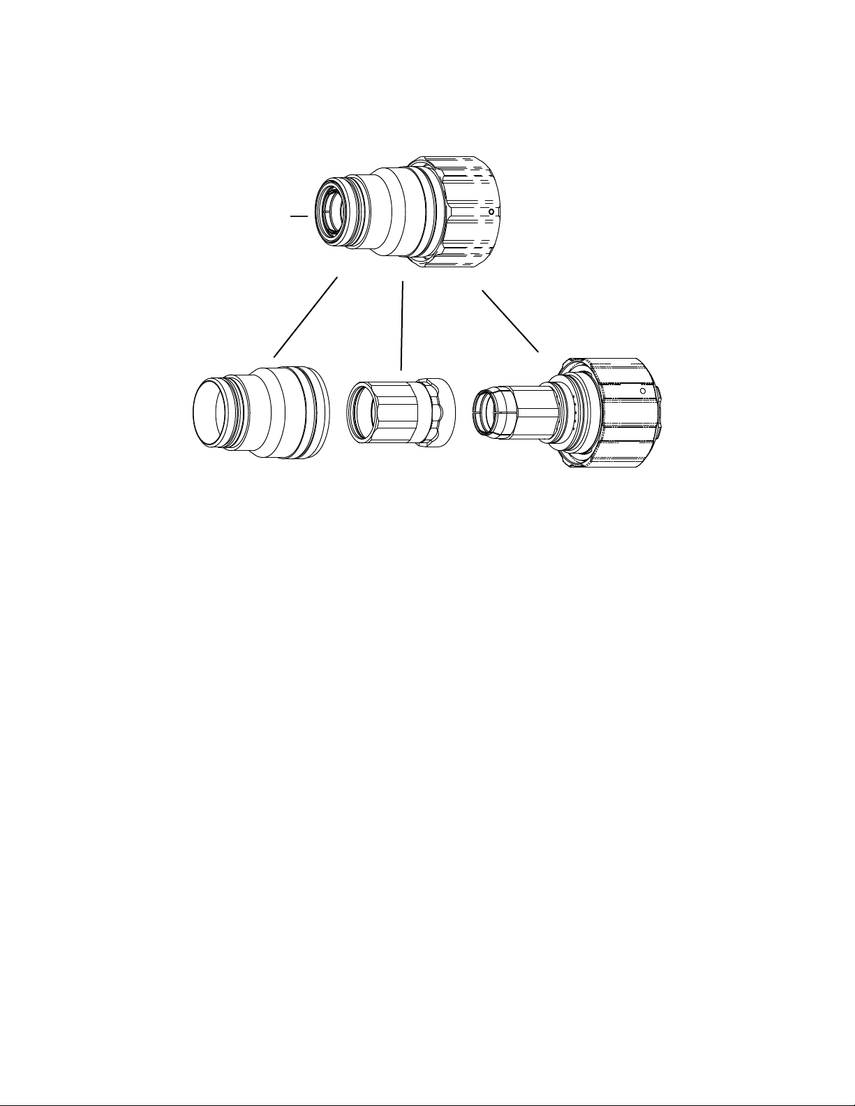
Cartridge Assembly (35-1022) Consumables
Cartridge Assembly
35-1022
Art # A-09242
35-1007
Shield Cup
2x-1005
Baffle
35-1023
Cartridge Body
TORCH DATA for AutoCut O
2
8-50 Manual 0-4831 Rev. AH
Page 43

Qty . Description Catalog Number
1 XT-301Torch Head Kit 35-1001
1 Torch Clamp Assembly 9-9336
1 Plasma Gas Hose 9-9450
1 Shield Gas Hose 9-9451
1 Torch Mounting Tube (includes Hardware Kit) 9-4700
1 Mounting Tube Hardware Kit (includes O-Ring) 9-4847
1 Ohmic Clip 9-9414
Coolant Supply,
Coolant Return,
and Pilot Leads
Torch Head
Torch Clamp
Coolant Return
Check Valve
and Connector
O-Ring
R
G
Positioning Tube
Leads Cover
End Cap
To Remote Arc Starter
To Torch Valve
Coolant Tube Assembly
Art # A-06981
Manual 0-4831 Rev. AH 8-51 TORCH DATA for AutoCut O
2
Page 44

O-Ring Selection for Torch Consumable Parts
Art # A-07248_AB
Electrodes
Tips
35-1069
O-Ring 9-9035
B
A
35-1078
O-Ring 9-9035
35-1071
O-Ring 9-9035
35-1055
35-1056
A - O-Ring 8-5525
B - O-Ring 9-9060
35-1085
O-Ring 9-9035
35-1080
O-Ring 9-9035
B - O-Ring 9-9060
A - O-Ring 8-5525
35-1086
*35-1057
B - O-Ring 9-9060
A - O-Ring 8-5525
35-1089
O-Ring 9-9035
O-Ring 9-9035
35-1058
B - O-Ring 9-9060
A - O-Ring 9-9038
B
A
Consumables O-Ring Locations and Catalog Numbers
Shield Cap
35-1034
TORCH DATA for AutoCut O
35-1051
B - O-Ring 9-9060
A - O-Ring 9-9038
O-Ring 9-9039
2
8-52 Manual 0-4831 Rev. AH
35-1053
B - O-Ring 9-9060
A - O-Ring 9-9038
35-1060
B - O-Ring 9-9060
A - O-Ring 9-9038
35-1062
B - O-Ring 9-9060
A - O-Ring 9-9038
Page 45

PA TENT INFORMATION
TMTM
TM
TMTM
XTXT
-301 Plasma Cutting T-301 Plasma Cutting T
XT
-301 Plasma Cutting T
XTXT
-301 Plasma Cutting T-301 Plasma Cutting T
The following parts are covered under U.S. and Foreign Patents as follows:
Catalog #Catalog #
Catalog #
Catalog #Catalog #
35-1020 Cartridge US Pat No(s) 6946616; 6919526; 6989505 Other Pat(s) Pending
35-1022 Cartridge US Pat No(s) 6946616; 6919526; 6989505 Other Pat(s) Pending
35-1068 Electrode US Pat No(s) 6946616; 6919526; 6989505; 6998566; D517577 Other Pat(s) Pending
35-1069 Electrode US Pat No(s) 6946616; 6919526; 6989505; 6998566; D517576 Other Pat(s) Pending
35-1070 Electrode US Pat No(s) 6946616; 6919526; 6989505; 6998566; D517576 Other Pat(s) Pending
35-1071 Electrode US Pat No(s) 6946616; 6919526; 6989505; 6998566; D517576 Other Pat(s) Pending
35-1072 Electrode US Pat No(s) 6946616; 6919526; 6989505; 6998566; D517576 Other Pat(s) Pending
35-1077 Electrode US Pat No(s) 6946616; 6919526; 6989505; 6998566 Other Pat(s) Pending
35-1078 Electrode US Pat No(s) 6946616; 6919526; D505963; 6989505; 6998566 Other Pat(s) Pending
35-1079 Electrode US Pat No(s) 6946616; 6919526; 6989505; 6998566 Other Pat(s) Pending
35-1080 Electrode US Pat No(s) 6946616; 6919526; 6989505; 6998566; D517577 Other Pat(s) Pending
35-1085 Electrode US Pat No(s) 6946616; 6919526; 6989505; 6998566 Other Pat(s) Pending
35-1086 Electrode US Pat No(s) 6946616; 6919526; 6989505; 6998566; D517576 Other Pat(s) Pending
35-1087 Electrode US Pat No(s) 6946616; 6919526; 6989505; 6998566; D517577 Other Pat(s) Pending
35-1088 Electrode US Pat No(s) 6946616; 6919526; 6989505; 6998566; D517576 Other Pat(s) Pending
35-1040 Plasma Gas Distributor US Pat No(s) 6946616; 6919526; 6989505 Other Pat(s) Pending
35-1041 Plasma Gas Distributor US Pat No(s) 6946616; 6919526; 6989505 Other Pat(s) Pending
35-1043 Plasma Gas Distributor US Pat No(s) 6946616; 6919526; 6989505 Other Pat(s) Pending
35-1044 Plasma Gas Distributor US Pat No(s) 6946616; 6919526; 6989505 Other Pat(s) Pending
35-1046 Plasma Gas Distributor US Pat No(s) 6946616; 6919526; 6989505 Other Pat(s) Pending
35-1024 Shield Cap US Pat No(s) 6946616; 6919526; 6989505 Other Pat(s) Pending
35-1025 Shield Cap US Pat No(s) 6946616; 6919526; 6989505 Other Pat(s) Pending
35-1026 Shield Cap US Pat No(s) 6946616; 6919526; 6989505 Other Pat(s) Pending
35-1027 Shield Cap US Pat No(s) 6946616; 6919526; 6989505 Other Pat(s) Pending
35-1034 Shield Cap US Pat No(s) 6946616; 6919526; 6989505 Other Pat(s) Pending
35-1028 Shield Cap US Pat No(s) 6946616; 6919526; 6989505 Other Pat(s) Pending
35-1029 Shield Cap US Pat No(s) 6946616; 6919526; 6989505 Other Pat(s) Pending
35-1030 Shield Cap US Pat No(s) 6946616; 6919526; 6989505 Other Pat(s) Pending
35-1031 Shield Cap US Pat No(s) 6946616; 6919526; 6989505 Other Pat(s) Pending
35-1032 Shield Cap US Pat No(s) 6946616; 6919526; 6989505 Other Pat(s) Pending
35-1033 Shield Cap US Pat No(s) 6946616; 6919526; 6989505 Other Pat(s) Pending
35-1035 Shield Cap US Pat No(s) 6946616; 6919526; 6989505 Other Pat(s) Pending
35-1036 Shield Cap US Pat No(s) 6946616; 6919526; 6989505 Other Pat(s) Pending
35-1037 Shield Cap US Pat No(s) 6946616; 6919526; 6989505 Other Pat(s) Pending
35-1039 Shield Cap US Pat No(s) 6946616; 6919526; 6989505 Other Pat(s) Pending
35-1275 Shield Cap US Pat No(s) 6946616; 6919526; 6989505 Other Pat(s) Pending
35-1016 Shield Cup US Pat No(s) 6946616; 6919526; 6989505 Other Pat(s) Pending
35-1018 Shield Cup US Pat No(s) 6946616; 6919526; 6989505 Other Pat(s) Pending
35-1082 Shield Gas Distributor US Pat No(s) 6946616; 6919526; 6989505 Other Pat(s) Pending
35-1272 Shield Gas Distributor US Pat No(s) 6946616; 6919526; 6989505 Other Pat(s) Pending
35-1273 Shield Gas Distributor US Pat No(s) 6946616; 6919526; 6989505 Other Pat(s) Pending
35-1274 Shield Gas Distributor US Pat No(s) 6946616; 6919526; 6989505 Other Pat(s) Pending
35-1280 Shield Gas Distributor US Pat No(s) 6946616; 6919526; 6989505 Other Pat(s) Pending
35-1281 Shield Gas Distributor US Pat No(s) 6946616; 6919526; 6989505 Other Pat(s) Pending
35-1282 Shield Gas Distributor US Pat No(s) 6946616; 6919526; 6989505 Other Pat(s) Pending
35-1283 Shield Gas Distributor US Pat No(s) 6946616; 6919526; 6989505 Other Pat(s) Pending
35-1019 Shield Retainer US Pat No(s) 6946616; 6919526; 6989505 Other Pat(s) Pending
35-1021 Shield Retainer US Pat No(s) 6946616; 6919526; 6989505 Other Pat(s) Pending
35-1050 Tip US Pat No(s) 6946616; 6919526; 6989505; 7005600; D519135; D524,336 Other
35-1051 Tip US Pat No(s) 6946616; 6919526; 6989505; 7005600; D519135; D524,336 Other
35-1052 Tip US Pat No(s) 6946616; 6919526; 6989505; 7005600; D519135; D524,336 Other
35-1053 Tip US Pat No(s) 6946616; 6919526; 6989505; 7005600; D519135; D524,336 Other
DescriptionDescription
Description
DescriptionDescription
Patent(s)Patent(s)
Patent(s)
Patent(s)Patent(s)
Pat(s) Pending
Pat(s)Pending
Pat(s) Pending
Pat(s)Pending
oror
ch Patentsch Patents
or
ch Patents
oror
ch Patentsch Patents
Manual 0-4831 Rev. AH 8-53 TORCH DATA for AutoCut O
2
Page 46

TMTM
TM
TMTM
-301 Plasma Cutting T-301 Plasma Cutting T
XTXT
-301 Plasma Cutting T
XT
-301 Plasma Cutting T-301 Plasma Cutting T
XTXT
oror
ch Patentsch Patents
or
ch Patents
oror
ch Patentsch Patents
The following parts are covered under U.S. and Foreign Patents as follows:
Catalog #Catalog #
Catalog #
Catalog #Catalog #
35-1054 Tip US Pat No(s) 6946616; 6919526; 6989505; 7005600; D519135; D524,336 Other
35-1055 Tip US Pat No(s) 6946616; 6919526; 6989505; 7005600 Other Pat(s) Pending
35-1056 Tip US Pat No(s) 6946616; 6919526; 6989505; 7005600 Other Pat(s) Pending
35-1057 Tip US Pat No(s) 6946616; 6919526; 6989505; 7005600 Other Pat(s) Pending
35-1058 Tip US Pat No(s) 6946616; 6919526; 6989505; 7005600; D519135; D524,336 Other
35-1060 Tip US Pat No(s) 6946616; 6919526; 6989505; 7005600; Other
35-1061 Tip US Pat No(s) 6946616; 6919526; 6989505; 7005600; D519135; D524,336 Other
35-1062 Tip US Pat No(s) 6946616; 6919526; 6989505; 7005600; D519135; D524,336 Other
35-1064 Tip US Pat No(s) 6946616; 6919526; 6989505; 7005600; Other
35-1001 Torch Head US Pat No(s) 6946616; 6919526; 6852944; 6989505; 7071443 Other Pat(s) Pending
DescriptionDescription
Description
DescriptionDescription
Patent(s)Patent(s)
Patent(s)
Patent(s)Patent(s)
Pat(s) Pending
Pat(s)Pending
Pat(s) Pending
Pat(s) Pending
Pat(s)Pending
Pat(s) Pending
The following parts are licensed under U.S. Patent No. 5,120,930 and 5,132,512:
Catalog #Catalog #
Catalog #
Catalog #Catalog #
35-1027 Shield Cap
35-1028 Shield Cap
35-1029 Shield Cap
35-1030 Shield Cap
35-1032 Shield Cap
DescriptionDescription
Description
DescriptionDescription
NOTE
This manual may refer to some or all of the parts listed.
TORCH DATA for AutoCut O
2
8-54 Manual 0-4831 Rev. AH
 Loading...