

Page 1

8. TORCH OPERATION
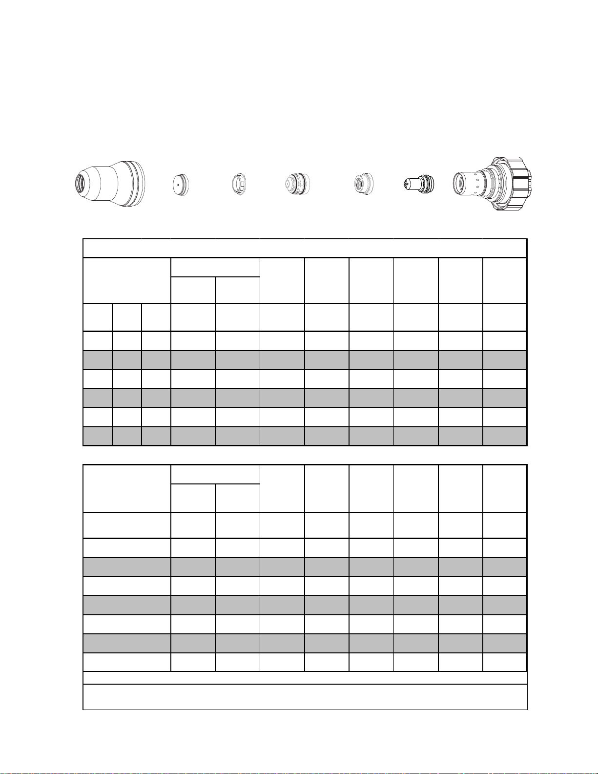
Torch Parts Selection
The application will determine which torch parts must be used. Refer to the cut charts for the proper torch parts to
install for a selected application.
Do not interchange parts. Make sure all torch parts correspond with the
plasma and shield gases in use for the application.
Pre-Setting Power Supply Controls
Set the Power Supply controls prior to operating the system as described in the power supply Operating Manual.
Refer to the cutting charts for the proper cutting parameters for the application.
Recommended Cutting Speeds
Cutting speed depends on material and thickness. The following factors may affect system performance:
• Torch parts wear; gas quality and mass flow / pressure; operator experience; torch standoff height; proper
work cable connection; alloying contents of material; cutting table capabilities & accuracy.
This information represents realistic expectations using recommended
practices and well-maintained systems. Actual speeds may vary from
those shown in the charts depending on the alloy content of the selected
material. Voltage ratings may vary depending on the CNC, cutting table,
or height controller.
For complete cutting speed chart data refer to the following pages.
Consumables Notes
Always assemble the consumable parts properly. Improper assembly may damage the parts or the torch head.
Ensure that parts are seated together correctly.
Always check the shield gas distributor for charring when changing parts. Do not use the distributor if it is charred.
Replace the shield gas distributor regularly to ensure proper performance.
Operational Notes
Always purge the torch after changing consumables or if the power supply has been shut off. The power supply's
built-in purge function may not be enough to properly purge the torch. Manually flow gas with the 'Test Cut Flow' and
'Test Pre-Flow' functions to help remove any remaining coolant from the lines.
Slightly increasing the preflow pressure may increase piercing ability on thicker materials. However, increasing the
preflow pressure too much may affect plasma starting reliability (misfiring).
Decreasing preflow pressure may improve piloting. Preflow pressure can be reduced without affecting cut performance as long as the pilot arc still transfers to the plate well. Decreasing preflow pressure too much will affect the
ability to transfer the arc to the plate and may cause damage to the tip.
Notes on Chart Measurements
Pressure measurements in the charts are in psi(g), not psi(a). 0 psi(g) = 14.7 psi(a) (1 atmosphere).
Ball settings are at the center of the gauge ball.
Manual 0-4825 Rev. AK 8-1 TORCH DATA for AutoCut Basic
Page 2
Ohmic Sensing
Ohmic sensing is not recommended with water shield. Water on the plate interferes electrically with the ohmic
sensing circuit.
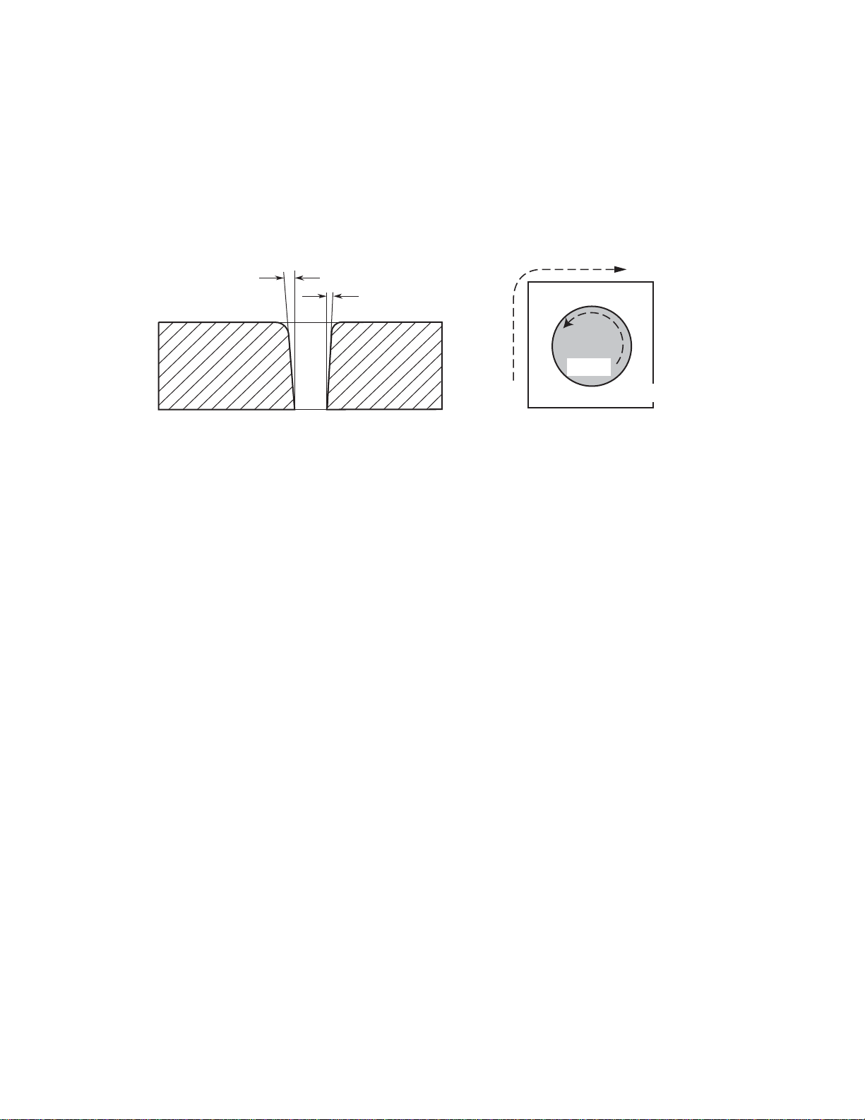
Direction of Cut
The plasma gas stream swirls as it leaves the torch to maintain a stable arc column. This swirl effect results in one
side of a cut being more square than the other. Viewed along the direction of travel, the right side of the cut is more
square than the left.
Left Side
Cut Angle
Right Side
Cut Angle
A-00512
Clockwise
Scrap
Counter-
Clockwise
Scrap
Workpiece
Art # A-04182
Side Characteristics Of Cut
To make a square - edged cut along an inside diameter of a circle, move the torch counterclockwise around the circle.
To keep the square edge along an outside diameter cut, move the torch in a clockwise direction.
Underwater Cutting
Cutting on a water table either underwater or with the water touching the plate or with a water muffler system is not
recommended. If a water table is used the water level must be a minimum of 4 inches / 100 mm from the bottom of the
plate. Failure to follow this recommendation could result in poor cut quality and short consumable parts life.
TORCH DATA for AutoCut Basic 8-2 Manual 0-4825 Rev. AK
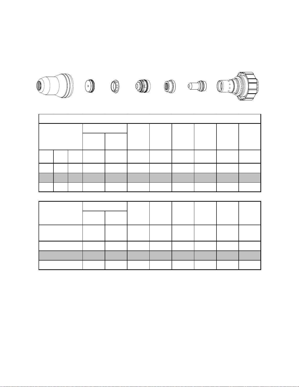
Page 3
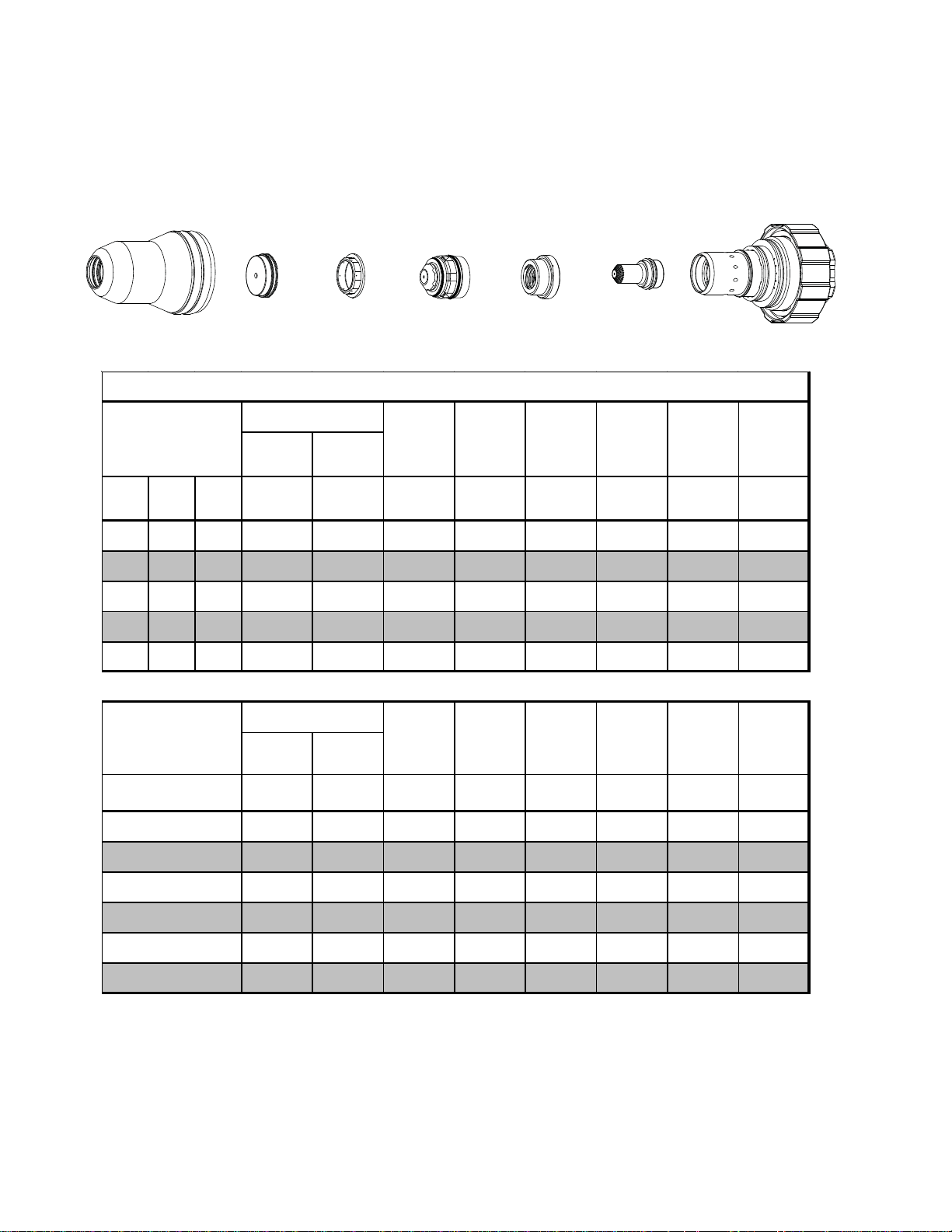
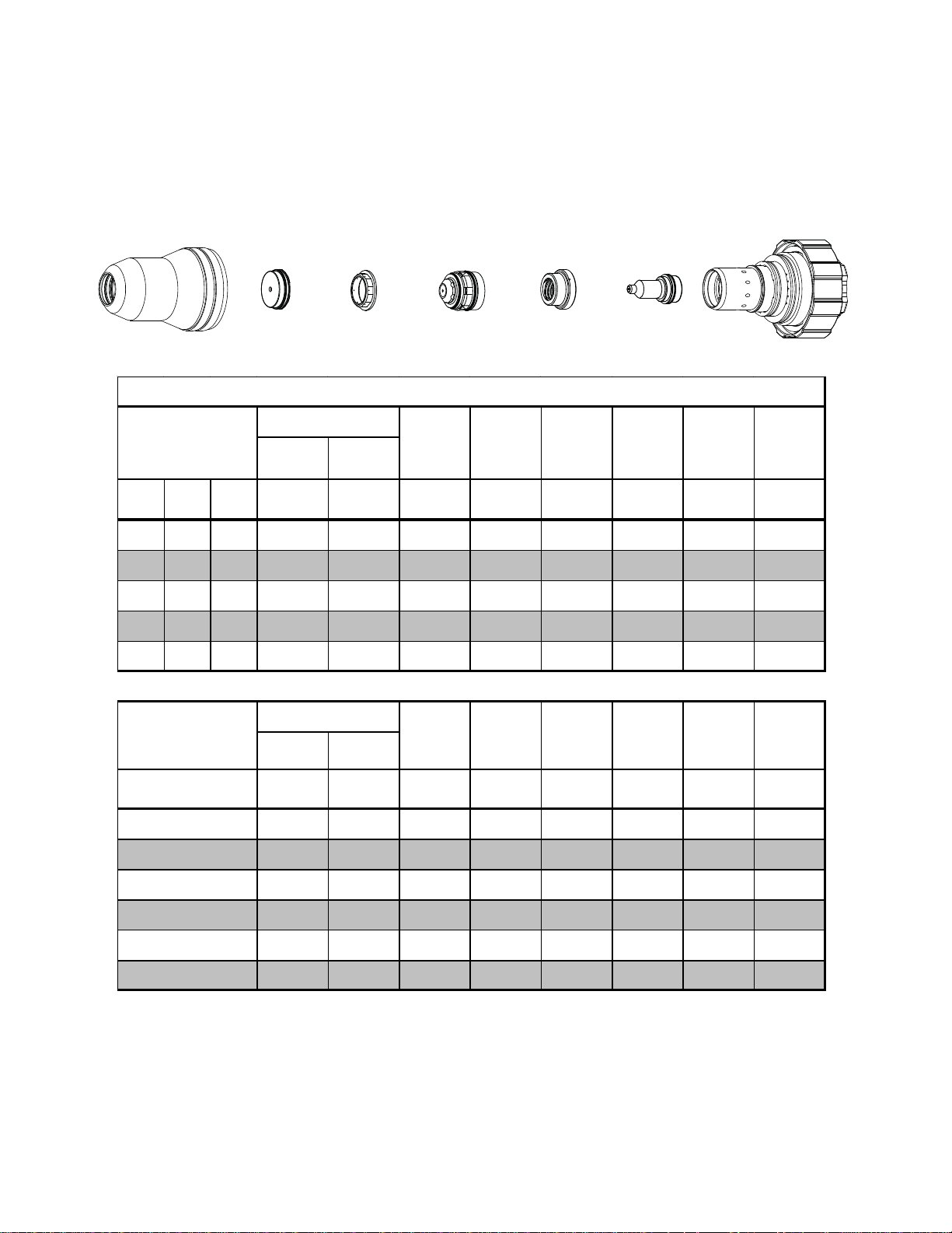
Mild Steel
55A
Air Plasma / Air Shield
Shield Cup
35-1016
Shield Cap
35-1025
Shield Gas
Distributor
35-1272
Tip
35-1051
Plasma Gas Distributor
35-1041
Electrode
35-1069
Cartridge
35-1020
Art # A-04941
55A Mild Steel (Air/Air)
Material
Thickness
(ga) (in) inch (PSI) (PSI) Volts
Cut Flow Pr essures
Plasma
(Air)
Shield
(Air)
Arc
Voltage
Torch
Working
Height
(in)
±0.005
Travel
Speed
(ipm) (in) (s ec) (in)
Initial
Piercing
Height
Pierce
Delay
Ker f Width
@ Rec.
Speed
21 0.033 70 20 152 0.188 500 0.200 0.1 0.079
16 0.060 70 20 154 0.188 300 0.200 0.1 0.086
10 0.135 92 80 166 0.188 190 0.200 0.2 0.079
3/16 0.188 92 80 166 0.188 130 0.250 0.3 0.089
1/4 0.250 92 80 170 0.188 95 0.250 0.3 0.090
Material
Thickness
(mm)
1
2
3
4
5
6
Cut Flow Pr essures
Plasma
(Air)
(Bar) (Bar) Volts
Shield
(Air)
Arc
Voltage
4.8 1.4 152 4.8 11500 5.1 0.1 2.0
4.8 1.4 157 4.8 6920 5.1 0.1 2.1
6.3 5.5 163 4.8 5460 5.1 0.2 2.0
6.3 5.5 166 4.8 4180 5.6 0.2 2.1
6.3 5.5 167 4.8 3180 6.4 0.3 2.3
6.3 5.5 169 4.8 2610 6.4 0.3 2.3
Torch
Working
Height
(mm)
±0.1
Travel
Speed
(mm/min) (mm) (sec) (mm)
Initial
Piercing
Height
Pierce
Delay
Ker f Width
@ Rec.
Speed
Manual 0-4825 Rev. AK 8-5 TORCH DATA for AutoCut Basic
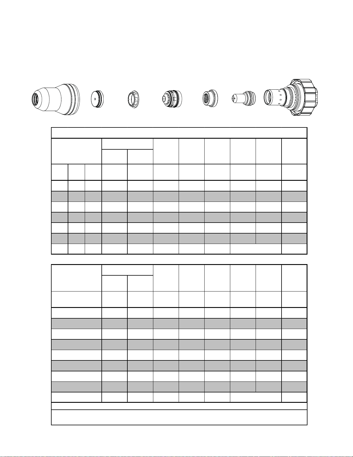
Page 4
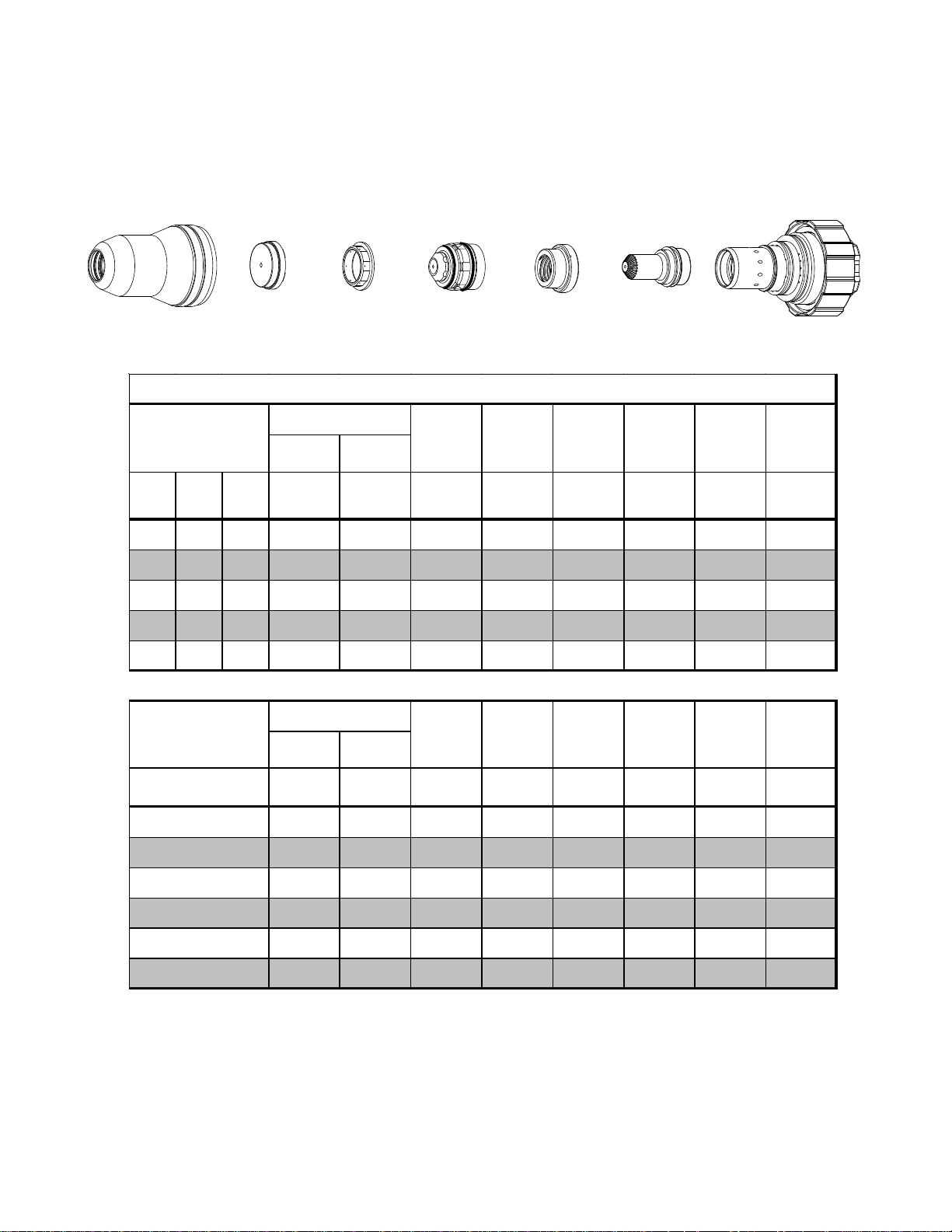
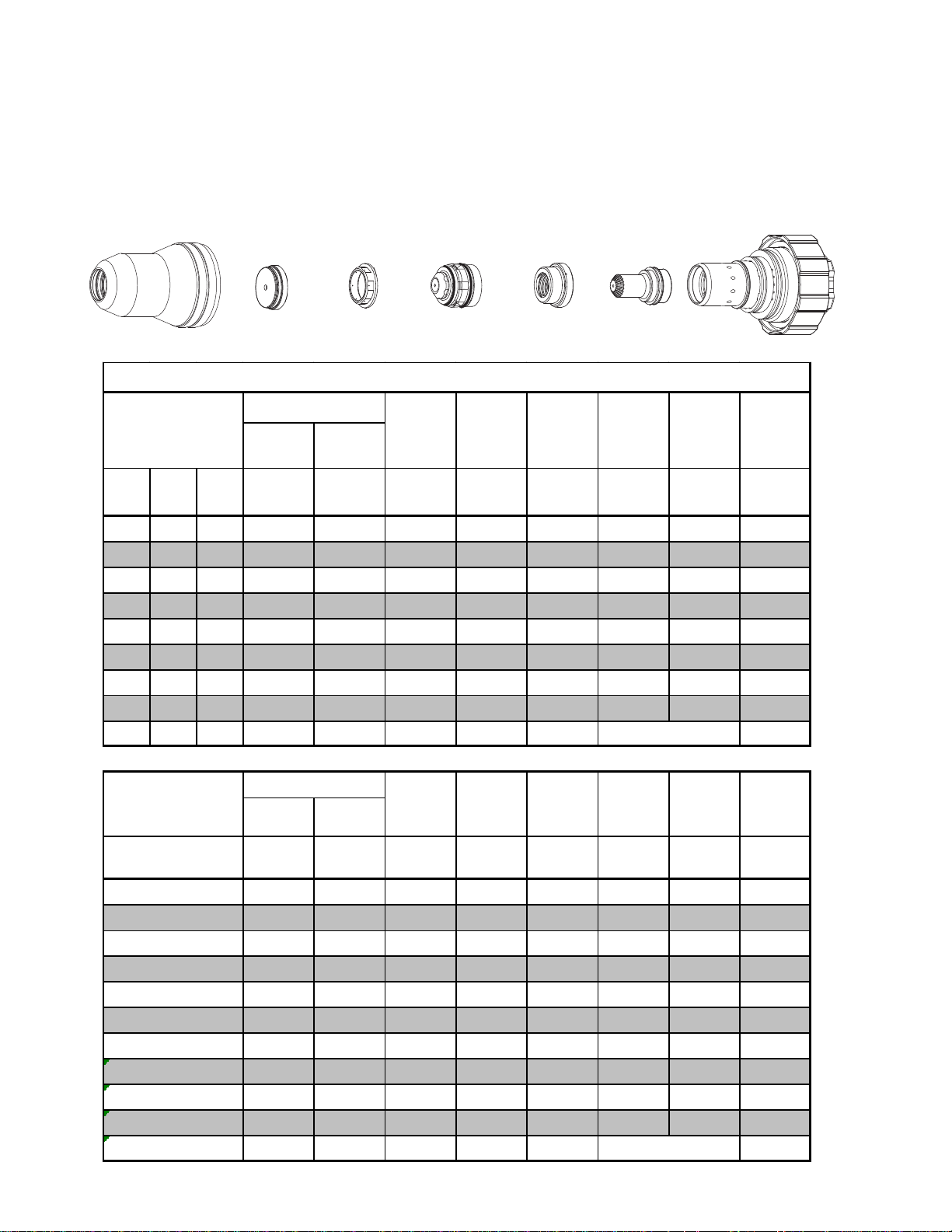
Mild Steel,
55A
Plasma / Air Shield
O
2
Shield Cup
35-1016
Shield Cap
35-1025
Shield Gas Distributor
35-1272
Tip
35-1051
Plasma Gas Distributor
35-1041
55A Mild Steel (O2/Air)
Electrode
35-1069
Cartridge
35-1020
Art # A-04940
Material
Thickness
(ga) (in) inch (PSI) (PSI) Volts
Cut Flow Pr essures
Plasma
(O2)
Shield
(Air)
Arc
Voltage
Torch
Working
Height
(in)
±0.005
Travel
Speed
(ipm) (in) (s ec) (in)
Initial
Piercing
Height
Pierce
Delay
Ker f Width
@ Rec.
Speed
21 0.033 70 20 120 0.125 600 0.200 0.0 0.073
16 0.060 70 20 120 0.125 400 0.200 0.0 0.071
10 0.135 80 20 126 0.125 180 0.200 0.2 0.083
3/16 0.188 80 20 127 0.125 120 0.200 0.2 0.081
1/4 0.250 80 20 128 0.125 85 0.200 0.3 0.086
Material
Thickness
(mm)
1
2
Cut Flow Pr essures
Plasma
(O2)
(Bar) (Bar) Volts
Shield
(Air)
Voltage
Arc
Torch
Working
Height
(mm)
±0.1
Travel
Speed
(mm/min) (mm) (sec) (mm)
Initial
Piercing
Height
Pierce
Delay
4.8 1.4 120 3.2 14040 5.1 0.0 1.8
4.8 1.4 121 3.2 8760 5.1 0.0 1.9
Ker f Width
@ Rec.
Speed
3
4
5
6
5.5 1.4 125 3.2 5830 5.1 0.2 2.0
5.5 1.4 126 3.2 3930 5.1 0.2 2.1
5.5 1.4 127 3.2 2920 5.1 0.2 2.1
5.5 1.4 128 3.2 2360 5.1 0.3 2.2
TORCH DATA for AutoCut Basic 8-6 Manual 0-4825 Rev. AK
Page 5
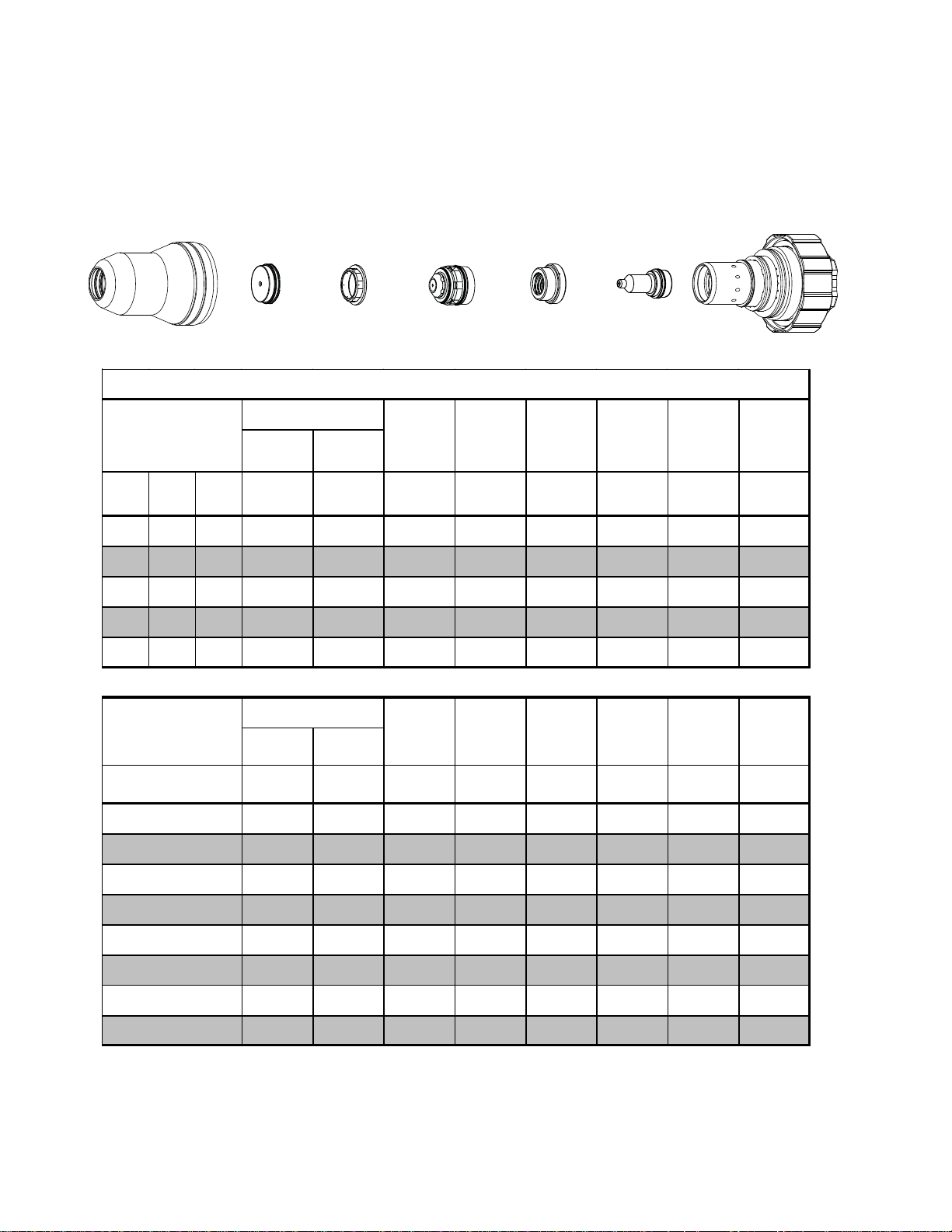
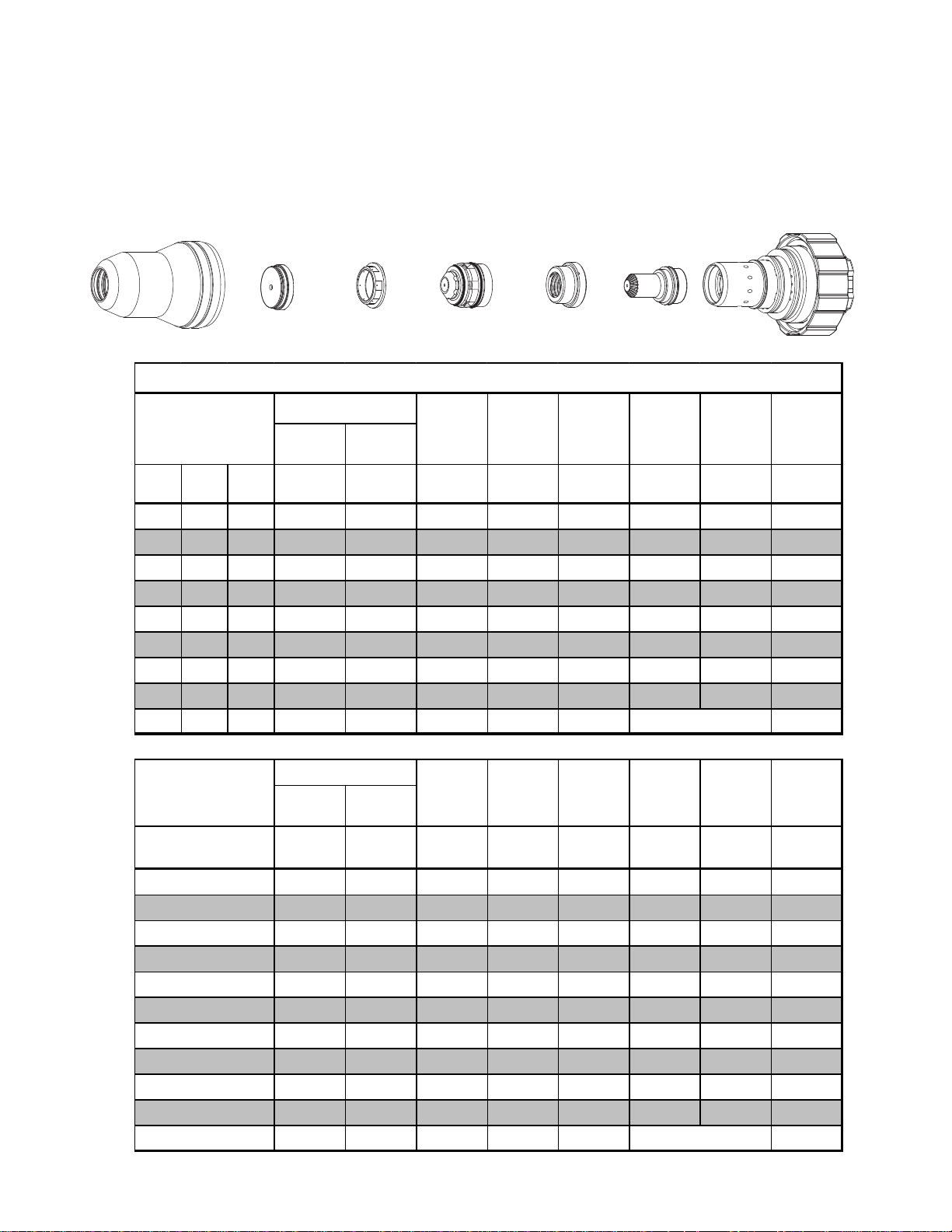
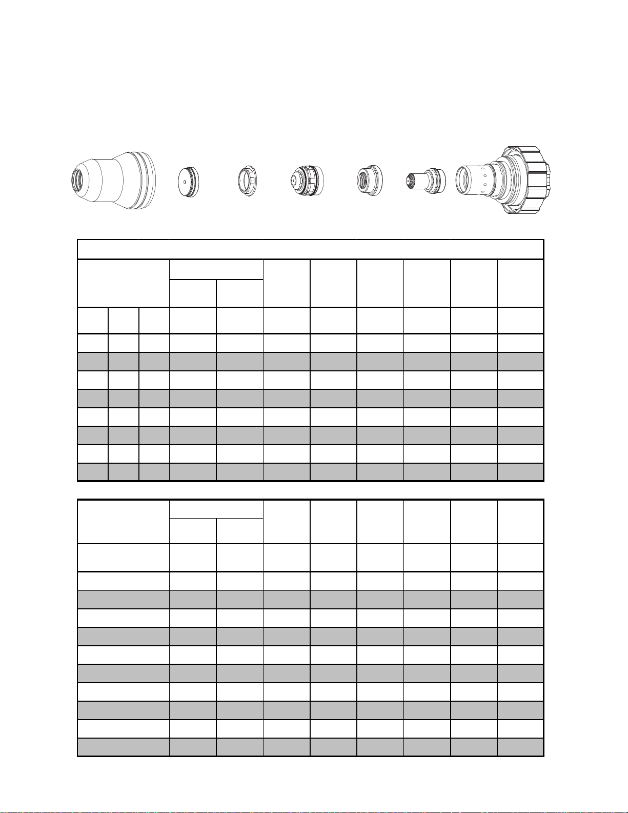
Stainless Steel
55A
Air Plasma / Air Shield
Shield Cup
35-1016
Shield Cap
35-1034
Shield Gas Distributor
35-1272
Tip
35-1060
Plasma Gas Distributor
35-1041
Electrode
35-1078
Cartridge
35-1020
Art # A-04942
55A Stainless Steel (Air/Air)
Material
Thickness
(ga) (in) inch (PSI) (PSI) Volts
Cut Flow Pressures
Plasma
(Air)
Shield
(Air)
Arc
Voltage
Torch
Working
Height
(in)
±0.005
Travel
Speed
(ipm)(in)(sec)(in)
Initial
Piercing
Height
Pierce
Delay
Ker f Width
@ Rec.
Speed
21 0.034 70 20 104 0.125 600 0.200 0.0 0.067
16 0.063 70 50 105 0.150 350 0.200 0.0 0.068
10 0.141 70 50 110 0.150 100 0.200 0.1 0.086
3/16 0.188 70 50 112 0.150 60 0.200 0.1 0.086
1/4 0.250 70 50 112 0.150 40 0.200 0.2 0.088
Material
Thickness
(mm)
0.8
1
1.5
2
3
4
5
6
Cut Flow Pressures
Plasma
(Air)
(Bar) (Bar) Volts
Shield
(Air)
Voltage
Arc
Torch
Working
Height
(mm)
±0.1
Travel
Speed
(mm/min) (mm) (sec) (mm)
Initial
Piercing
Height
Pierce
Delay
4.8 1.4 104 3.2 15240 5.1 0.0 1.7
4.8 1.4 104 3.3 14060 5.1 0.0 1.7
4.8 3.4 105 3.7 9750 5.1 0.0 1.7
4.8 3.4 106 3.8 7610 5.1 0.0 1.8
4.8 3.4 109 3.8 4400 5.1 0.1 2.1
4.8 3.4 111 3.8 2180 5.1 0.1 2.2
4.8 3.4 112 3.8 1450 5.1 0.1 2.2
4.8 3.4 112 3.8 1130 5.1 0.2 2.2
Ker f Width
@ Rec.
Speed
Manual 0-4825 Rev. AK 8-7 TORCH DATA for AutoCut Basic
Page 6
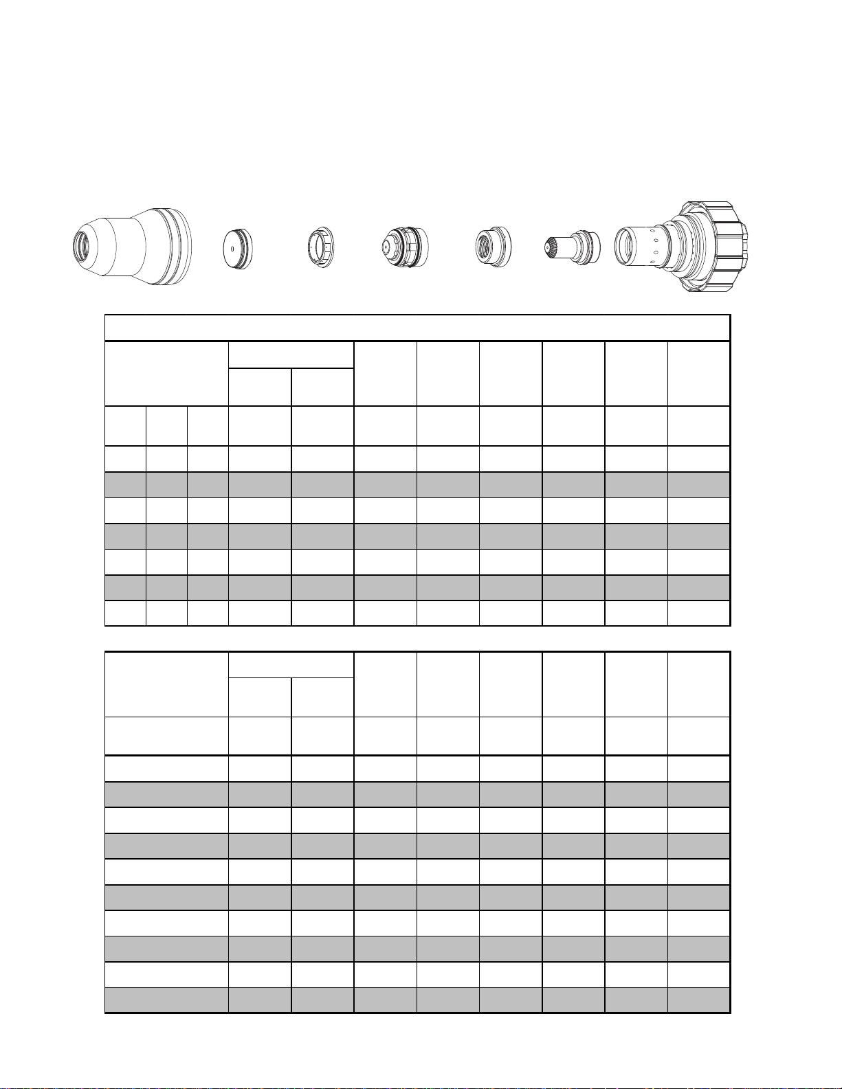
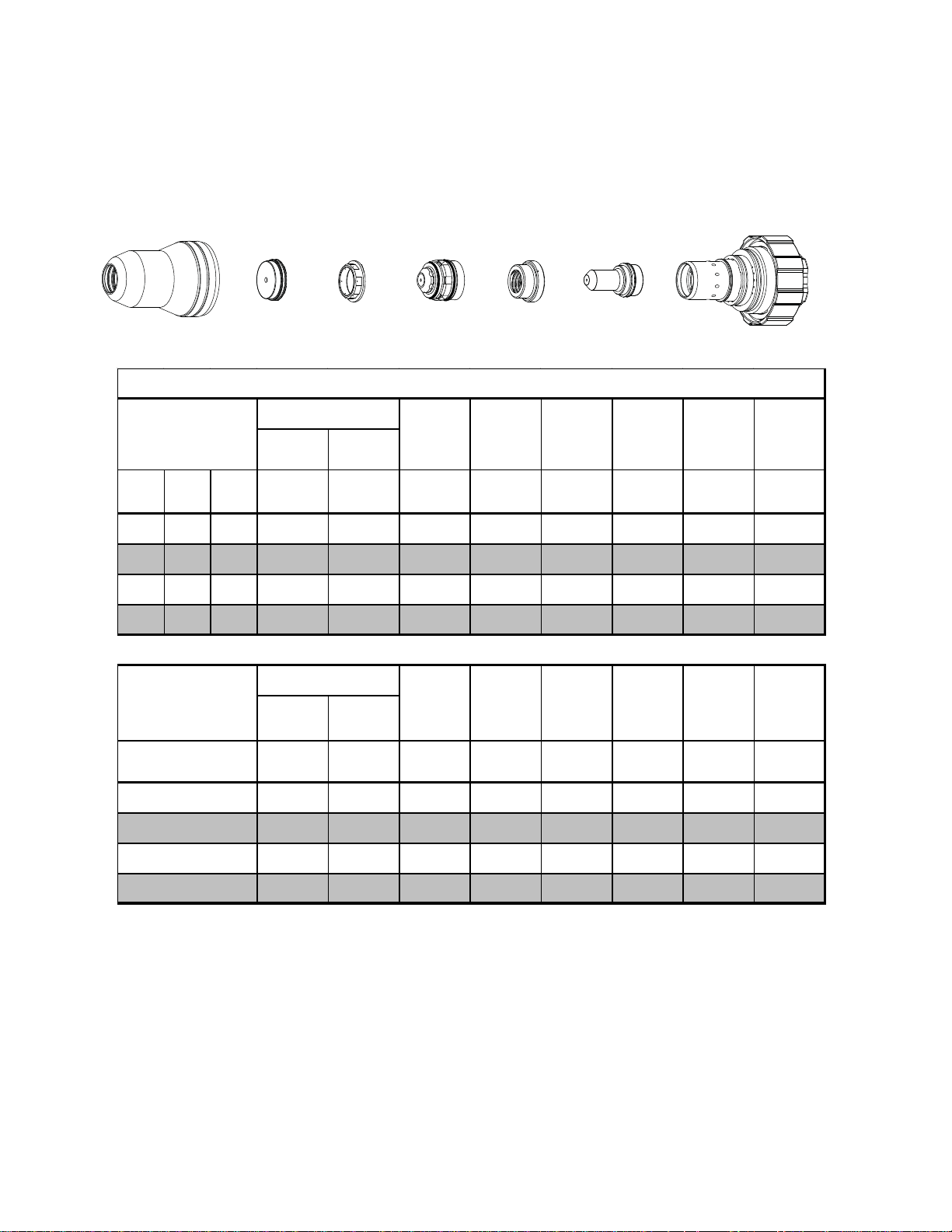
Aluminum
55A
Air Plasma / Air Shield
Shield Cup
35-1016
Shield Cap
35-1034
Shield Gas Distributor
35-1272
Tip
35-1060
Plasma Gas Distributor
35-1041
Electrode
35-1078
Cartridge
35-1020
Art # A-04942
55A Aluminum (Air/Air)
Material
Thickness
(ga) (in) inch (PSI) (PSI) Volts
Cut Flow Pr essures
Plasma
(Air)
Shield
(Air)
Arc
Voltage
Torch
Working
Height
(in)
±0.005
Travel
Speed
(ipm) (in) (s ec) (in)
Initial
Piercing
Height
Pierce
Delay
Ker f Width
@ Rec.
Speed
23 0.031 70 50 100 0.100 600 0.150 0.0 0.066
16 0.064 70 50 105 0.100 400 0.200 0.0 0.070
10 0.135 70 50 115 0.150 140 0.200 0.0 0.084
3/16 0.188 70 50 120 0.150 100 0.200 0.0 0.084
1/4 0.250 70 50 122 0.150 50 0.200 0.1 0.089
Material
Thickness
(mm)
1
2
3
4
5
6
Cut Flow Pr essures
Plasma
(Air)
(Bar) (Bar) Volts
Shield
(Air)
Voltage
Arc
Torch
Working
Height
(mm)
±0.1
Travel
Speed
(mm/min) (mm) (sec) (mm)
Initial
Piercing
Height
Pierce
Delay
4.8 3.4 101 2.5 13950 4.1 0.0 1.7
4.8 3.4 107 2.8 8790 5.1 0.0 1.9
4.8 3.4 113 3.5 5130 5.1 0.0 2.0
4.8 3.4 117 3.8 3130 5.1 0.0 2.1
4.8 3.4 120 3.8 2360 5.1 0.0 2.2
4.8 3.4 122 3.8 1550 5.1 0.1 2.2
Ker f Width
@ Rec.
Speed
TORCH DATA for AutoCut Basic 8-8 Manual 0-4825 Rev. AK
Page 7
Mild Steel
100A
Air Plasma / Air Shield
Shield Cup
35-1016
Shield Cap
35-1027
Shield
Gas Distributor
35-1272
Tip
35-1053
Plasma
Gas Distributor
35-1041
Electrode
35-1071
Cartridge
35-1020
Art # A-04863
100A Mild Ste e l (Air/Air)
Material
Thickness
(ga) (in) inch (PSI) (PSI) Volts
Cut Flow Pressures
Plasma
(Air)
Shield
(Air)
Arc
Voltage
Torch
Working
Height
(in)
±0.005
Travel
Speed
(ipm)(in)(sec)(in)
Initial
Piercing
Height
Pierce
Delay
Ker f Width
@ Rec.
Speed
16 0.060 90 45 149 0.110 600 0.250 0.1 0.072
10 0.135 90 45 145 0.110 300 0.250 0.2 0.065
3/16 0.188 90 45 149 0.110 210 0.250 0.3 0.073
1/4 0.250 90 45 152 0.120 150 0.300 0.3 0.078
3/8 0.375 90 45 152 0.130 85 0.300 0.3 0.091
1/2 0.500 90 45 159 0.140 75 0.300 0.3 0.095
5/8 0.625 90 45 153 0.140 55 0.350 0.5 0.099
3/4 0.750 90 45 163 0.150 30 0.350 0.6 0.120
1 1.00 90 45 180 0.200 20 0.112
Edge Start
Material
Thickness
(mm)
2
3
4
5
6
8
10
12
15
20
25
Cut Flow Pressures
Plasma
(Air)
(Bar) (Bar) Volts
Shield
(Air)
Arc
Voltage
6.2 3.1 148 2.8 13340 6.4 0.1 1.8
6.2 3.1 146 2.8 9340 6.4 0.2 1.7
6.2 3.1 147 2.8 6650 6.4 0.2 1.7
6.2 3.1 149 2.8 5120 6.5 0.3 1.9
6.2 3.1 151 3.0 4150 7.3 0.3 2.0
6.2 3.1 152 3.2 2950 7.6 0.3 2.2
6.2 3.1 153 3.3 2120 7.6 0.3 2.3
6.2 3.1 157 3.5 1960 7.6 0.3 2.4
6.2 3.1 155 3.6 1540 8.5 0.4 2.5
6.2 3.1 166 4.0 720 9.5 0.6 3.0
6.2 3.1 179 5.0 520 2.9
Torch
Working
Height
(mm)
±0.1
Travel
Speed
(mm/min) (mm) (sec) (mm)
Initial
Piercing
Height
Pierce
Delay
Ker f Width
@ Rec.
Speed
Edge Start
Manual 0-4825 Rev. AK 8-9 TORCH DATA for AutoCut Basic
Page 8
Mild Steel
100A
Plasma / Air Shield
O
2
Gas Distributor
Torch
(in)
Plasma
Electrode
35-1041
/Air)
2
Travel
Speed
(ipm)(in)(sec)(in)
35-1071
Initial
Piercing
Height
Cartridge
35-1020
Art # A-04863
Pierce
Delay
Ker f Width
@ Rec.
Speed
Shield Cup
35-1016
Shield Cap
35-1027
Shield
Gas Distributor
35-1272
35-1053
100A Mild Ste e l (O
Material
Thickness
(ga) (in) inch (PSI) (PSI) Volts
Cut FlowPressures
Plasma
(O
Shield
)
2
(Air)
Arc
Voltage
Tip
Working
Height
±0.005
16 0.060 94 49 127 0.110 500 0.250 0.1 0.071
10 0.135 94 49 134 0.110 240 0.250 0.2 0.081
3/16 0.188 94 49 128 0.120 185 0.250 0.3 0.073
1/4 0.250 94 49 130 0.120 130 0.300 0.3 0.095
3/8 0.375 94 49 138 0.130 80 0.300 0.3 0.113
1/2 0.500 94 49 138 0.140 57 0.300 0.3 0.113
5/8 0.625 94 49 144 0.140 45 0.350 0.5 0.111
3/4 0.750 94 49 150 0.150 25 0.350 0.6 0.138
1 1.000 94 49 164 0.200 10 0.140
Edge Start
Material
Thickness
(mm)
2
3
4
5
6
8
10
12
15
20
25
Cut Flow Pressures
Plasma
(O
(Bar) (Bar) Volts
Shield
)
2
(Air)
Voltage
Arc
Torch
Working
Height
(mm)
±0.1
Travel
Speed
(mm/min) (mm) (sec) (mm)
Initial
Piercing
Height
Pierce
Delay
6.5 3.4 129 2.8 11050 6.4 0.1 1.9
6.5 3.4 132 2.8 7580 6.4 0.2 2.0
6.5 3.4 131 2.9 5500 6.4 0.2 2.0
6.5 3.4 128 3.1 4500 6.5 0.3 1.9
6.5 3.4 130 3.1 3610 7.3 0.3 2.3
6.5 3.4 134 3.2 2640 7.6 0.3 2.7
6.5 3.4 138 3.3 1950 7.6 0.3 2.9
6.5 3.4 138 3.5 1580 7.6 0.3 2.9
6.5 3.4 142 3.6 1230 8.5 0.4 2.8
6.5 3.4 152 4.0 580 9.5 0.6 3.5
6.5 3.4 163 5.0 280 3.6
Edge Start
Ker f Width
@ Rec.
Speed
TORCH DATA for AutoCut Basic 8-10 Manual 0-4825 Rev. AK
Page 9
Stainless Steel
100A
Air Plasma / Air Shield
Shield Cup
35-1016
Shield Cap
35-1027
Shield
Gas Distributor
35-1272
Tip
35-1053
Plasma
Gas Distributor
35-1041
Electrode
35-1071
Cartridge
35-1020
Art # A-04863
100A Stainless Ste e l (Air/Air)
Material
Thickness
(ga) (in) inch (PSI) (PSI) Volts
Cut Flow Pressures
Plasma
(Air)
Shield
(Air)
Arc
Voltage
Torch
Working
Height
(in)
±0.005
Travel
Speed
(ipm)(in)(sec)(in)
Initial
Piercing
Height
Pierce
Delay
Ker f Width
@ Rec.
Speed
16 0.063 85 42 144 0.080 500 0.200 0.0 0.099
10 0.141 85 42 150 0.100 225 0.325 0.0 0.102
3/16 0.188 85 42 153 0.140 175 0.325 0.1 0.105
1/4 0.250 85 42 155 0.140 100 0.325 0.1 0.105
3/8 0.375 85 42 160 0.140 65 0.325 0.2 0.110
1/2 0.500 85 42 166 0.160 45 0.325 0.4 0.112
5/8 0.625 85 42 165 0.160 35 0.350 1.0 0.114
Material
Thickness
(mm)
1.5
2
3
4
5
6
8
10
12
Cut Flow Pressures
Plasma
(Air)
(Bar) (Bar) Volts
Shield
(Air)
Voltage
Arc
Torch
Working
Height
(mm)
±0.1
5.7 2.9 144 2.0 12700 5.1 0.0 2.4
5.7 2.9 145 2.1 11290 5.7 0.0 2.5
5.7 2.9 149 2.0 6330 8.3 0.0 2.6
5.7 2.9 150 3.6 7030 8.3 0.1 2.7
5.7 2.9 153 3.6 4170 8.3 0.1 2.7
5.7 2.9 155 3.6 2960 8.3 0.1 2.7
5.7 2.9 158 3.6 2080 8.3 0.2 2.7
5.7 2.9 161 3.6 1580 8.3 0.2 2.8
5.7 2.9 165 4.0 1260 8.3 0.4 2.8
Travel
Speed
(mm/min) (mm) (sec) (mm)
Initial
Piercing
Height
Pierce
Delay
Ker f Width
@ Rec.
Speed
15
5.7 2.9 165 4.1 960 8.7 0.8 2.9
Manual 0-4825 Rev. AK 8-11 TORCH DATA for AutoCut Basic
Page 10
Stainless Steel
100A
H35 Plasma / N
Shield Cup
35-1016
Material
Thickness
(ga) (in) inch (PSI) (PSI) Volts
3/8 0.375 100 80 145 0.130 50 0.250 0.3 0.090
1/2 0.500 100 80 148 0.130 37 0.250 0.5 0.100
5/8 0.625 100 80 155 0.140 26 0.250 0.6 0.115
Shield
2
Shield Cap
35-1034
Cut Flow Pressures
Plasma
(H35)
Shield
Gas Distributor
35-1272
Tip
35-1062
100A Stainless Steel (H35/N
Shield
)
(N
2
Arc
Voltage
Working
Height
±0.005
Plasma
Gas Distributor
35-1041
Torch
(in)
Electrode
35-1080
)
2
Travel
Speed
(ipm)(in)(sec)(in)
Initial
Piercing
Height
Cartridge
35-1020
Art # A-04938
Pierce
Delay
Ker f Width
@ Rec.
Speed
Material
Thickness
(mm)
10
12
15
Cut Flow Pressures
Plasma
(H35)
(Bar) (Bar) Volts
Shield
)
(N
2
Voltage
Arc
Torch
Working
Height
(mm)
±0.1
Travel
Speed
(mm/min) (mm) (sec) (mm)
Initial
Piercing
Height
Pierce
Delay
6.9 5.5 145 3.3 1220 6.4 0.3 2.3
6.9 5.5 147 3.3 1010 6.4 0.5 2.5
6.9 5.5 151 3.5 740 6.4 0.6 2.8
Ker f Width
@ Rec.
Speed
TORCH DATA for AutoCut Basic 8-12 Manual 0-4825 Rev. AK
Page 11
Stainless Steel
100A
Plasma / H2O Shield
N
2
Shield Cup
35-1016
Material
Thickness
(ga) (in) inch (PSI ) Ball * Volts
Shield Cap
35-1034
Shield Gas Distributor
35-1272
Cut Flow Pressures
Plasma
(N
2
Shield
)
10 0.141 100 5 160 0.125 160 0.200 0.000 0.074
3/16 0.188 100 5 157 0.125 100 0.250 0.300 0.080
1/4 0.250 100 5 155 0.125 60 0.250 0.300 0.086
3/8 0.375 100 5 159 0.125 50 0.250 0.300 0.087
1/2 0.500 100 5 169 0.130 35 0.300 0.500 0.100
5/8 0.625 100 5 175 0.140 30 0.300 0.600 0.110
Tip
35-1053
100A Stainless Steel (N
Arc
Voltage
(H2O)
Torch
Working
Height
±0.005
Plasma Gas Distributor*
35-1041
O)
2/H2
Travel
Speed
(in)
(ipm)(in)(sec)(in)
Electrode
35-1089
Initial
Piercing
Height
Cartridge
35-1020
Art # A-04939
Pierce
Delay
Ker f Width
@ Rec.
Speed
3/4 0.750 100 5 177 0.150 25 **0.125
Edge St art
** Note m easur ed, ext rap olat ed value.
Material
Thickness
(mm)
3
4
5
6
8
10
12
15
20
Cut Flow Pressures
Plasma
(N
2
(Bar ) Ba ll * V olts
Shield
)
(H2O)
Voltage
Arc
Torch
Working
Height
(mm)
±0.1
6.9 5 161 3.2 4810 4.5 0 1.8
6.9 5 159 3.2 3530 5.5 0.1 1.9
6.9 5 157 3.2 2400 6.4 0.3 2.1
6.9 5 155 3.2 1750 6.4 0.3 2.2
6.9 5 157 3.2 1390 6.4 0.3 2.2
6.9 5 160 3.2 1210 6.5 0.3 2.3
6.9 5 167 3.3 970 7.3 0.5 2.5
6.9 5 173 3.5 800 7.6 0.6 2.7
6.9 5 178 3.9 600 3.3
Travel
Speed
(mm/min) (mm) (sec) (mm)
Initial
Piercing
Height
Pierce
Delay
Edge St art
* Ball setting for shi eld wat er i s s et using a l i ne pres s ure of 55 PS I / 3. 8 Bar
NOTE: Ohmic height sens i ng is not rec om m ended wit h wat er s hi el d.
W at er on t he plate int erferes electri call y wit h the ohmic s ensing sy stem .
Ker f Width
@ Rec.
Speed
Manual 0-4825 Rev. AK 8-13 TORCH DATA for AutoCut Basic
Page 12
Aluminum
100A
Air Plasma / Air Shield
Shield Cup
35-1016
Shield Cap
35-1027
Shield
Gas Distributor
35-1272
Tip
35-1053
Plasma
Gas Distributor
35-1041
Electrode
35-1071
Cartridge
35-1020
Art # A-04863
100A Aluminum (Air/Air)
Material
Thickness
(ga) (in) inch (PSI) (PSI) Volts
Cut Flow Pressures
Plasma
(Air)
Shield
(Air)
Arc
Voltage
Torch
Working
Height
(in)
±0.005
Travel
Speed
(ipm)(in)(sec)(in)
Initial
Piercing
Height
Pierce
Delay
Ker f Width
@ Rec.
Speed
16 0.064 85 42 154 0.130 500 0.200 0.0 0.103
10 0.135 85 42 157 0.130 260 0.200 0.0 0.106
3/16 0.188 85 42 156 0.130 120 0.325 0.1 0.100
1/4 0.250 85 42 158 0.140 100 0.325 0.2 0.104
3/8 0.375 85 42 162 0.140 75 0.325 0.2 0.107
1/2 0.500 85 42 168 0.140 45 0.325 0.3 0.109
5/8 0.625 85 42 175 0.140 35 0.325 0.4 0.112
3/4 0.750 85 42 180 0.180 35 0.350 1.0 0.121
Material
Thickness
(mm)
2
3
4
5
6
8
10
12
15
Cut Flow Pressures
Plasma
(Air)
(Bar) (Bar) Volts
Shield
(Air)
Arc
Voltage
5.9 2.9 155 3.3 11430 5.1 0.0 2.6
5.9 2.9 156 3.3 8050 5.1 0.0 2.7
5.9 2.9 157 3.3 5100 6.4 0.0 2.6
5.9 2.9 156 3.3 2980 8.3 0.1 2.6
5.9 2.9 158 3.5 2650 8.3 0.2 2.6
5.9 2.9 160 3.6 2210 8.3 0.2 2.7
5.9 2.9 163 3.6 1790 8.3 0.2 2.7
5.9 2.9 167 3.6 1310 8.3 0.3 2.8
5.9 2.9 173 3.6 960 8.3 0.4 2.8
Torch
Working
Height
(mm)
±0.1
Travel
Speed
(mm/min) (mm) (sec) (mm)
Initial
Piercing
Height
Pierce
Delay
Ker f Width
@ Rec.
Speed
20
5.9 2.9 181 4.9 890 9.9 1.0 3.1
TORCH DATA for AutoCut Basic 8-14 Manual 0-4825 Rev. AK
Page 13
Aluminum
100A
H35 Plasma / N
Shield Cup
35-1016
Material
Thickness
(ga) (in) inch (PSI) (PSI) Volts
Shield
2
Shield Cap
35-1034
Cut Flow Pressures
Plasma
Gas Distributor
(H35)
Shield
35-1272
Shield
3/8 0.375 120 50 150 0.188 60 0.350 0.1 0.100
1/2 0.500 120 50 156 0.188 40 0.350 0.4 0.110
5/8 0.625 120 50 160 0.188 30 0.350 0.5 0.113
3/4 0.750 120 50 171 0.250 20 0.350 0.6 0.130
Tip
35-1062
100A Aluminum (H35/N
(N
Arc
Voltage
)
2
Working
Plasma
Gas Distributor
35-1041
Torch
Height
(in)
±0.005
Electrode
35-1080
)
2
Travel
Speed
(ipm)(in)(sec)(in)
Initial
Piercing
Height
Cartridge
35-1020
Art # A-04938
Pierce
Delay
Ker f Width
@ Rec.
Speed
Material
Thickness
(mm)
10
12
15
20
Cut Flow Pressures
Plasma
(H35)
(PSI) (PSI) Volts
Shield
)
(N
2
Voltage
Arc
Torch
Working
Height
(mm)
±0.1
Travel
Speed
(mm/min) (mm) (sec) (mm)
Initial
Piercing
Height
Pierce
Delay
8.3 3.4 151 4.8 1450 8.9 0.1 2.6
8.3 3.4 155 4.8 1130 8.9 0.3 2.7
8.3 3.4 159 4.8 830 8.9 0.5 2.8
8.3 3.4 174 6.8 430 8.9 0.6 3.4
Ker f Width
@ Rec.
Speed
Manual 0-4825 Rev. AK 8-15 TORCH DATA for AutoCut Basic
Page 14
Aluminum
100A
Plasma / H2O Shield
N
2
Shield Cup
35-1016
Shield Cap
35-1034
Shield
Gas Distributor
35-1272
Tip
35-1053
Plasma
Gas Distributor
35-1041
Electrode
35-1089
Cartridge
35-1020
Art # A-06788
100A Aluminum (N2/H2O)
Material
Thickness
(ga) (in) inch (PS I) Ball * Volt s
Cut Flow Pressures
Plasma
(N
2
Shield
)
(H2O)
Arc
Voltage
Torch
Working
Height
(in)
±0.005
Travel
Speed
(ipm)(in)(sec)(in)
Initial
Piercing
Height
Pierce
Delay
Ker f Width
@ Rec.
Speed
10 0.135 100 5 148 0.125 170 0.200 0.0 0.072
3/16 0.188 100 5 158 0.125 80 0.250 0.3 0.080
1/4 0.250 100 5 158 0.125 60 0.250 0.3 0.085
3/8 0.375 100 5 161 0.125 50 0.250 0.3 0.086
1/2 0.500 100 5 170 0.130 35 0.300 0.6 0.091
5/8 0.625 100 5 180 0.140 20 0.300 0.8 0.120
Material
Thickness
(mm)
4
5
6
8
10
12
15
Cut Flow Pressures
Plasma
(N
2
(Bar) Ball * Volt s
Shield
)
(H2O)
Arc
Voltage
6.9 5 152 3.2 3350 5.6 0.1 1.9
6.9 5 158 3.2 1960 6.4 0.3 2.1
6.9 5 158 3.2 1640 6.4 0.3 2.1
6.9 5 160 3.2 1390 6.4 0.3 2.2
6.9 5 162 3.2 1210 6.5 0.3 2.2
6.9 5 168 3.3 970 7.3 0.5 2.3
6.9 5 177 3.5 610 7.6 0.7 2.8
Torch
Working
Height
(mm)
±0.1
Travel
Speed
(mm/min) (mm) (sec) (mm)
Initial
Piercing
Height
Pierce
Delay
* Bal l set t i ng for shiel d wat er is set us i ng a l ine pres sure of 55 PSI / 3. 8 B ar
NOTE: Ohmic height sensing is not recommended with water shield.
Water on the plate int erferes elect rically wit h t he ohm ic sens ing sy st em.
Ker f Width
@ Rec.
Speed
TORCH DATA for AutoCut Basic 8-16 Manual 0-4825 Rev. AK
Page 15

This Chart for Custom e r S e ttings
Make Copies as Desired
Material
Thickness
(ga) (in) inch (PSI) (PSI) Volts
Cut Flow Pressures
Plasma
(H35)
Shield
)
(N
2
Arc
Voltage
3/8 0.375
1/2 0.500
5/8 0.625
3/4 0.750
Material
Thickness
(mm)
Cut Flow Pressures
Plasma
(H35)
(PSI) (PSI) Volts
Shield
(N
)
2
Voltage
Arc
Torch
Working
Height
(in)
±0.005
Torch
Working
Height
(mm)
±0.1
Travel
Speed
(ipm)(in)(sec)(in)
Travel
Speed
(mm/min) (mm) (sec) (mm)
Initial
Piercing
Height
Initial
Piercing
Height
Pierce
Delay
Pierce
Delay
Ker f Width
@ Rec.
Speed
Ker f Width
@ Rec.
Speed
10
12
15
20
Manual 0-4825 Rev. AK 8-17 TORCH DATA for AutoCut Basic
Page 16

This Page Intentionally Blank
TORCH DATA for AutoCut Basic 8-18 Manual 0-4825 Rev. AK
Page 17

Material
Gases
Used
Consumable
Description
100A 55A
Electrode
35-1071 35-1069
Plasma Gas Distributor
35-1041 35-1041
Tip
35-1053 35-1051
O2/Air 35-1272 35-1272
Air/Air
Shield Retainer
Shield Cup
35-1016 35-1016
Cartridge Assy
35-1020 35-1020
35-1080
H35/N2
35-1078
35-1089
N2/H2O
35-1071
Air/Air
35-1041 35-1041
35-1062
H35/N2
35-1060
H35/N2 35-1053
N2/H2O
Air/Air 35-1272 35-1272
35-1034 35-1034
35-1027
Air/Air
Shield Retainer
Shield Cup
35-1016 35-1016
Cartridge Assy
35-1020 35-1020
Stainless
Steel/
Aluminum
Electrode
Plasma Gas Distributor
Tip
Shield Gas Distributor
Shield Cap
Auto-Cut Basic
Mild Steel
Shield Gas Distributor
Shield Cap
35-1027
35-1025
Art # A-08447
Manual 0-4825 Rev. AK 8-19 TORCH DATA for AutoCut Basic
Page 18

This Page Intentionally Blank
TORCH DATA for AutoCut Basic 8-20 Manual 0-4825 Rev. AK
Page 19

Mild Steel
200A
Air Plasma / Air Shield
Shield
Retainer
35-1019
Shield Cup
35-1018
Shield
Cap
35-1028
Shield Gas
Distributor
35-1280
Tip
35-1055
Plasma Gas
Distributor
35-1041
Electrode
35-1085
Cartridge
35-1020
Art # A-06988
200A Mild Ste e l (Air/Air)
Material
Thickness
Cut Flow Pressures
Plasma
(Air)
Shield
(Air)
Arc
Voltage
(ga) (in) inch (PSI) (PSI) Volts
Torch
Working
Height
(in)
±0.005
Tr avel
Speed
Initial
Piercing
Height
Pierce
Delay
(ipm) (in) (sec) (in)
1/4 0.250 90 60 163 0.140 185 0.300 0 0.096
3/8 0.375 90 60 160 0.140 130 0.300 0.1 0.131
1/2 0.500 90 60 162 0.140 100 0.300 0.3 0.150
5/8 0.625 90 60 164 0.140 75 0.300 0.4 0.158
3/4 0.750 90 60 168 0.180 60 0.350 0.5 0.176
1 1.000 90 60 177 0.200 35 0.500 1.5 0.189
1-1/4 1.250 90 60 185 0.250 20 0.209
1-1/2 1.500 90 60 189 0.250 15 0.225
2 2.000 90 60 204 0.300 10 0.270
Edge Start
Edge Start
Edge Start
Ker f Width
@ Rec.
Speed
Material
Thickness
(mm)
6
8
10
12
15
20
25
32
38
44
50
Cut Flow Pressures
Plasma
(Air)
Shield
(Air)
Voltage
(Bar) (Bar) Volts
Arc
Torch
Working
Height
(mm)
±0.1
6.2 4.1 163 3.6 4700 7.6 0 2.4
6.2 4.1 161 3.6 3970 7.6 0.1 2.9
6.2 4.1 160 3.6 3190 7.6 0.1 3.4
6.2 4.1 162 3.6 2710 7.6 0.3 3.7
6.2 4.1 163 3.6 2080 7.6 0.4 4.0
6.2 4.1 169 4.6 1430 9.5 0.6 4.5
6.2 4.1 176 5.0 920 12.5 1.4 4.8
6.2 4.1 185 6.4 500 5.3
6.2 4.1 189 6.4 380 5.7
6.2 4.1 196 6.9 320 6.2
6.2 4.1 203 7.5 260 6.8
Tr avel
Speed
Initial
Piercing
Height
Pierce
Delay
Ker f Width
@ Rec.
Speed
(mm/min) (mm) (sec) (mm)
Edge Start
Edge Start
Edge Start
Edge Start
Manual 0-4825 Rev. AK 8-23 TORCH DATA for AutoCut Basic
Page 20

Mild Steel
200A
Plasma / Air Shield
O
2
Shield Retainer
35-1019
Material
Thickness
(ga) (in) inch (PSI) (PSI) Volts
1/4 0.250 90 58 154 0.140 190 0.300 0.1 0.153
3/8 0.375 90 58 156 0.140 140 0.300 0.3 0.159
1/2 0.500 90 58 158 0.140 100 0.350 0.4 0.168
5/8 0.625 90 58 161 0.140 70 0.350 0.5 0.183
3/4 0.750 90 58 168 0.160 60 0.400 0.6 0.192
1 1.000 90 58 170 0.180 40 0.500 0.9 0.207
1 1/4 1.250
1 1/ 2 1.500
22.000
Shield Cup
35-1018
Shield Cap
35-1029
Cut Flow
Plasma
(O
90 58 175 0.200 30 0.500 2 0.216
90 58 178 0.200 20 0.237
90 58 203 0.250 10 0.268
Shield
)
2
Shield Gas
Distributor
35-1281
200A Mild S t e el O
Arc
(Air)
Voltage
Tip
35-1056
/Air
2
Torch
Working
Height
(in)
±0.005
Art # A-07612
Pierce
Delay
Cartridge
35-1020
Kerf Width
@ Rec.
Speed
Plasma Gas
Distributor
35-1041
Travel
Speed
(ipm) (in) (sec) (in)
Electrode
35-1085
Initial
Piercing
Height
Edge Start
Edge Start
200A Mild Steel O2/Air
Material
Thickness
(mm)
6
8
10
12
15
20
25
32
38 Edge Start
44 Edge Start
50 Edge Start
Bold type
indicates maximum piercing parameters.
Cut Flow
Plasma
(O
(Bar) (Bar) Volts
6.2 4.0 154 3.6 4830 7.6 0.1 3.9
6.2 4.0 155 3.6 4170 7.6 0.2 4.0
6.2 4.0 156 3.6 3400 7.8 0.3 4.1
6.2 4.0 158 3.6 2760 8.6 0.4 4.2
6.2 4.0 160 3.6 1990 8.9 0.5 4.5
6.2 4.0 168 4.1 1450 12.7 0.6 4.9
6.2 4.0 170 4.5 1050 12.7 0.9 5.2
6.2 4.0 175 5.1 750 12.7 2.1 5.5
6.2 4.0 178 5.1 510 6.0
6.2 4.0 190 5.7 390 6.4
6.2 4.0 201 6.3 270 6.8
Shield
)
(Air)
2
Arc
Voltage
Torch
Working
Height
(mm)
±0.1
Travel
Speed
(mm/min) (mm) (sec) (mm)
Bold italic
indicates edge star ts only .
Initial
Piercing
Height
Pierce
Delay
Kerf Width
@ Rec.
Speed
TORCH DATA for AutoCut Basic 8-24 Manual 0-4825 Rev. AK
Page 21

Stainless Steel
200A
Air Plasma / Air Shield
Shield
Retainer
35-1019
Material
Thickness
(ga) (in) inch (PSI) (PSI) Volts
3/16
Shield Cup
35-1018
Cut Flow Pr essures
Plasma
0.1875
Shield
Cap
35-1030
(Air)
90
Shield Gas
Distributor
35-1282
200A Stainl ess Steel Air/Air
Shield
(Air)
Arc
Voltage
70 168 0.140 300 0.300 0 0.169
Tip
35-1055
Plasma Gas
Distributor
Torch
Working
Height
(in)
±0.005
Electrode
35-1041
Travel
Speed
(ipm) (in) (sec) (in)
35-1085
Initial
Piercing
Height
Art # A-07594
Pierce
Delay
1/4 0.250 90 70 165 0.140 275 0.300 0.1 0.162
3/8 0.375 90 70 167 0.140 200 0.300 0.2 0.169
1/2 0.500 90 70 170 0.140 145 0.350 0.3 0.169
5/8 0.625 90 70 170 0.140 110 0.400 0.4 0.174
3/4 0.750 90 70 171 0.160 75 0.450 0.5 0.176
7/8 0.875 90 70 172 0.170 55 0.450 0.7 0.181
1 1.000 90 70 175 0.180 40 0.500 1.3 0.181
1 1/4 1. 250
1 1/2 1. 500
2 2.000 90 70 198 0.200 8 0.230
90 70 185 0.200 20 0.500 3 0.207
90 70 191 0.200 13 0.220
Edge Start
Edge Start
Cartridge
35-1020
Kerf Width
@ Rec.
Speed
200A Stainl ess Steel Air/Air
Material
Thickness
(mm)
5
6
8
10
12
15
20
25
32
38
50
Cut Flow Pr essures
Plasma
(Air)
Shield
(Air)
Voltage
(Bar) (Bar) Volts
Arc
Torch
Working
Height
(mm)
±0.1
Travel
Speed
Initial
Piercing
Height
Pierce
Delay
(mm/min) (mm) (sec) (mm)
6.2 4.8 168 3.6 7530 7.6 0 4.1
6.2 4.8 166 3.6 7130 7.6 0.1 4.1
6.2 4.8 166 3.6 6000 7.6 0.2 4.2
6.2 4.8 166 3.6 4870 7.8 0.2 4.3
6.2 4.8 169 3.6 3990 8.6 0.3 4.3
6.2 4.8 170 3.6 3040 9.8 0.4 4.4
6.2 4.8 171 4.1 1750 11.4 0.6 4.5
6.2 4.8 175 4.5 1060 12.5 1.2 4.6
6.2 4.8 185 5.1 500 12.7 3.0 5.3
6.2 4.8 191 5.1 330 5.6
6.2 4.8 198 5.1 210 5.8
Edge Start
Edge Start
Kerf Width
@ Rec.
Speed
Manual 0-4825 Rev. AK 8-25 TORCH DATA for AutoCut Basic
Page 22

Stainless Steel
200A
H35 Plasma / N
Shield Cup
35-1016
Shield **
2
Shield Cap
< 1” (25mm)
35-1031
>
1” + (25mm)
35-1032
Shield Gas
Distributor
35-1273
200A Stainless Steel (H35/N
Material
Thickness
(ga) (in) inch (PSI) (PSI) Volts
Cut Flow
Plasma
(H35)
Shield
3/8 0.375 70 120 157 0.240 90 0.300 0.5 0.158
1/2 0.5 70 120 160 0.260 65 0.300 0.6 0.171
5/8 0.625 70 120 165 0.280 50 0.350 0.7 0.178
3/4 0.75 70 120 168 0.300 40 0.450 0.8 0.180
7/8 0.875 70 120 172 0.300 30 0.450 0.9 0.178
1 1 70 120 175 0.325 25 0.450 1.3 0.185
1 1/4 1.25 70 120 180 0. 300 20 0.175
1 1/2 1.5 70 120 182 0.300 15 0.180
2 2 70 120 185 0.325 10 0.195
(N
2
)
Tip
35-1058
Arc
Voltage
Plasma Gas
Distributor
35-1043
Torch
Working
Height
(in)
±0.005
Cartridge
Electrode
35-1087
)
2
Travel
Speed
(ipm) (in) (sec) (in)
Initial
Piercing
Height*
35-1020
Art # A-07610
Pierce
Delay
Ker f Width
@ Rec.
Speed
Edge Start
Edge Start
Edge Start
Material
Thickness
(mm)
10
12
15
20
25
32
38
50
Cut Flow
Plasma
(H35)
(Bar) (Bar) Volts
Shield
(N
2
)
Arc
Voltage
4.8 8.3 157 6.2 2190 7.6 0.5 4.1
4.8 8.3 159 6.5 1790 7.6 0.6 4.3
4.8 8.3 164 7.3 1380 8.5 0.7 4.5
4.8 8.3 169 7.8 940 11.4 0.8 4.6
4.8 8.3 175 8.3 650 11.4 1.2 4.7
4.8 8.3 180 8.3 500 4.5
4.8 8.3 182 8.3 380 4.6
4.8 8.3 185 8.3 260 4.9
Torch
Working
Height
(mm)
±0.1
Travel
Speed
(mm/mi
n)
Initial
Piercing
Height*
(m m) (sec) (mm)
Pierce
Delay
Edge Start
Edge Start
Edge Start
* Lock pierc e hei ght bet ween 0.5" to 1" to avoid torch hi t ting t he pierce met al puddle.
**Requires Fi rm ware versi on 3. 2 or higher.
Ker f Width
@ Rec.
Speed
TORCH DATA for AutoCut Basic 8-26 Manual 0-4825 Rev. AK
Page 23

(
2
Stainless Steel
200A
N
Plasma / H2O Shield
2
Shield Cup
Shield Cap
Shield Gas
Distributor
Tip
Plasma Gas
Distributor
Electrode
Cartridge
This Art Is For Reference ONLY
Shield Cup
Material
Thickness
(ga) (in) inch (PSI) (Ball) Volts
7/8 0.875 110 5 180 0.250 50 0.300 0.7 0.141
1 1.000 110 5 185 0.300 40 0.350 1.0 0.151
Material
Thickness
BOLD TYPE
Requires CCM version 3.4 or l ater. Requires G CM ve r sion 3. 2 o r later.
* Pre ssure of the water supply lin e should be re gulated at 55 PSI / 3.4 Bar by customer pr essure regulator.
Ohmic height sensing is not recommended with water shield. Water on the plate interferes electrically with the
Note1:
ohmic sensing circ ui t.
Water source used f or shield must be demineralized.
Note2:
Shield
35-1039 35-1273 35-1064
1/2 0.500 90 5 170 0.160 90 0.300 0.4 0.117
5/8 0.625 90 5 173 0.200 75 0.300 0.5 0.128
3/4 0.750 110 5 175 0.250 60 0.300 0.6 0.132
1.25 1.250 110 5 189 0.350 30 0.163
1.5 1.500 110 5 202 0.350 20 0.175
1.75 1.750 110 5 205 0.400 15 0.180
(mm)
12
15
20
25
32
38
44
indicates maximum piercing parameters.
Cap
Shield Gas
Distributor
Cut Flo ws / P ressures
Plasma (N2)
Cut Flo ws / P ressures
Plasma (N
2
(Bar) (Ball) Volts
6.2 5 169 4.1 2300 7.6 0.4 2.9
6.2 5 173 5.0 1950 7.6 0.5 3.2
7.6 5 178 6.4 1450 7.6 0.6 3.4
7.6 5 185 7.6 1000 8.9 1.0 3.8
7.6 5 190 8.9 750 4.1
7.6 5 202 8.9 500 4.4
7.6 5 205 10.2 380 4.6
Tip
Shield
H
O)*
Shield
)
(H
O)*
Plasma Gas
Distributor
35-1046 35-1089 35-102035-1016
Arc
Voltage
Arc
Voltage
BOLD ITALIC
Electrode Cartridge
Torch
Working
Height
(in)
±0.005
Torch
Working
Height
(mm)
±0.1
Travel
Speed
(ipm) (in) (sec) (in)
Travel
Speed
(mm/min) (mm) (sec) (mm)
indicates edge star ts only .
Art # A-07958_AB
Initial
Piercing
Height
Edge Start
Edge Start
Edge Start
Initial
Piercing
Height
Edge Start
Edge Start
Edge Start
Pierce
Delay
Pierce
Delay
Kerf Width
Kerf Width
@ Rec.
Speed
@ Rec.
Speed
Manual 0-4825 Rev. AK 8-27 TORCH DATA for AutoCut Basic
Page 24

Aluminum
200A
Air Plasma / Air Shield
Shield
Retainer
35-1019
Shield Cup
35-1018
Shield
Cap
35-1030
Shield Gas
Distributor
35-1282
35-1055
200A Aluminum Air/Air
Cut F l ow
Material
Thickness
Pressures
Plasma
(Air)
Shield
(Air)
Arc
Voltage
(ga) (in) inch (PSI) (PSI) Volts
3/16 0.1875 90 70 170 0.14 225 0.300 0.0 0.173
1/4
0.250
90 70 174 0.140 195 0.300 0.1 0.177
3/8 0.375 90 70 179 0.140 150 0.300 0.2 0.173
1/2 0.500 90 70 181 0.140 115 0.350 0.3 0.166
5/8 0.625 90 70 182 0.140 90 0.400 0.4 0.164
3/4 0.750 90 70 185 0.160 70 0.400 0.5 0.171
7/8 0.875 90 70 189 0.170 55 0.450 0.7 0.175
1 1.000 90 70 196 0.180 40 0.500 1.3 0.197
1 1/4 1. 250 90 70 205 0. 200 25 0. 500 3. 0 0.185
1 1/2 1. 500 90 70 210 0. 200 15 0.198
2 2.000
90 70 213 0.200 8 0.220
Tip
Plasma Gas
Distributor
35-1041
Torch
Working
Height
(in)
±0.005
Cartridge
35-1020
Art # A-07594
Pierce
Delay
Kerf
Width
@ Rec.
Speed
Travel
Speed
Electrode
35-1085
Initial
Piercing
Height
(ipm) (in) (sec) (in)
Edge Start
Edge Start
Material
Thickness
(mm)
5
6
8
10
12
15
20
25
32
38
50
Cut F l ow
Pressures
Plasma
(Air)
Shield
(Air)
Voltage
(Bar) (Bar) Volts
Arc
Torch
Working
Height
(mm)
±0.1
Travel
Speed
Initial
Piercing
Height
Pierce
Delay
(mm/min) (mm) (sec) (mm)
6.2 4.8 171 3.6 5600 7.6 0 4.4
6.2 4.8 173 3.6 5120 7.6 0.1 4.5
6.2 4.8 177 3.6 4360 7.6 0.2 4.4
6.2 4.8 179 3.6 3680 7.8 0.2 4.4
6.2 4.8 181 3.6 3120 8.6 0.3 4.3
6.2 4.8 182 4.1 2460 9.8 0.4 4.2
6.2 4.8 186 4.5 1660 10.5 0.6 4.4
6.2 4.8 195 5.1 1060 12.5 1.2 4.6
6.2 4.8 205 5.1 630 12.7 2.9 4.7
6.2 4.8 210 5.1 390 5.0
6.2 4.8 213 5.1 210 5.6
Edge Start
Edge Start
Kerf
Width
@ Rec.
Speed
TORCH DATA for AutoCut Basic 8-28 Manual 0-4825 Rev. AK
Page 25

Aluminum
200A
H35 Plasma / N
Shield Cup
35-1016
Shield **
2
Shield Cap
< 1” (25mm)
35-1031
>
1” + (25mm)
35-1032
Shield Gas
Distributor
35-1273
200A Aluminu m (H35/N
Material
Thickness
(ga) (in) inch (PSI) (PSI) Volts
Cut Flow
Plasma
(H35)
Shield
(N
)
2
1/2 0.5 70 100 155 0.300 150 0.350 0.2 0.163
5/8 0.625 70 100 160 0.300 110 0.350 0.3 0.169
3/4 0.75 70 100 166 0.300 70 0.400 0.4 0.177
7/8 0.875 70 100 171 0.350 55 0.450 0.5 0.192
1 1 70 100 177 0.350 40 0.196
1 1/4 1.25 70 100 181 0.350 32 0. 180
1 1/ 2 1. 5 7 0 100 188 0 .350 25 0 .190
2 2 70 100 190 0.350 15 0.195
Tip
35-1058
Arc
Voltage
Plasma Gas
Distributor
35-1043
Torch
Working
Height
(in)
±0.005
Cartridge
Electrode
35-1087
)
2
Travel
Speed
(ipm) (in) (sec) (in)
Initial
Piercing
Height*
35-1020
Art # A-07610
Pierce
Delay
Edge Start
Edge Start
Edge Start
Edge Start
Kerf Width
@ Rec.
Speed
Material
Thickness
(m m)
12
15
20
25
32
38
50
Cut Flow
Plasma
(H35)
(Bar) (Bar) Volts
Shield
(N
)
2
Arc
Voltage
4.8 6.9 155 7.6 3810 7.6 0.2 4.3
4.8 6.9 159 7.6 3070 8.9 0.3 4.3
4.8 6.9 167 8.0 1660 10.5 0.4 4.6
4.8 6.9 176 8.9 1060 5.0
4.8 6.9 181 8.9 810 4.6
4.8 6.9 188 8.9 640 4.8
4.8 6.9 190 8.9 400 4.9
Torch
Working
Height
(mm)
±0.1
Travel
Speed
(mm/min)
Initial
Piercing
Height*
(m m) (sec) (mm)
Pierce
Delay
Kerf Width
Edge Start
Edge Start
Edge Start
Edge Start
* Lock pierce height for first 0.5" to 1" of c utting to avoid torch hitting the pierce metal puddle.
Sli ght l y decreas ing t he shiel d gas pres sure mini m i z es dross on alum inum cut t i ng
**Requires Fi rm ware versi on 3. 2 or higher.
@ Rec.
Speed
Manual 0-4825 Rev. AK 8-29 TORCH DATA for AutoCut Basic
Page 26

(
2
Aluminum
200A
Plasma / H2O Shield
N
2
Shield Cup
Shield Cap
Shield Gas
Distributor
Tip
Plasma Gas
Distributor
Electrode
Cartridge
Initial
Piercing
Height
Edge Start
Edge Start
Edge Start
Initial
Piercing
Height
Edge Start
Edge Start44
Edge Start
Art # A-07958_AB
Pierce
Delay
Pierce
Delay
Kerf Width
Kerf Width
This Art Is For Reference ONLY
Shield Cup
Material
Thickness
(ga) (in) inch (PSI) (Ball) Volts
7/8 0.875 110 5 178 0.300 60 0.350 0.8 0.152
1 1.000 110 5 188 0.350 40 0.400 0.9 0.165
Material
Thickness
BOLD TYPE
Requires CCM version 3.4 or later . Requires GC M version 3. 2 or later .
* Pre ssure of the water supply li ne should be r egulated at 55 PSI / 3.4 B ar by customer pressure regulat o r .
Ohmic height sensing is not re c ommended with water shield. Water on the plate int er feres elect rically wit h the
Note1:
ohmic sensing circuit.
Water source used f or shield must be demineralized.
Note2:
Shield
35-1039 35-1273 35-1064
1/2 0.500 70 5 156 0.250 110 0.300 0.3 0.133
5/8 0.625 70 5 165 0.250 100 0.300 0.4 0.140
3/4 0.750 110 5 170 0.250 70 0.300 0.6 0.138
1 1/ 4 1.250 110 5 197 0.350 30 0.400 1.9 0.175
1 1/2 1.5 00 110 5 198 0.350 20 0.181
1 3/4 1.7 50 110 5 198 0.350 18 0.188
2 2.000 110 5 198 0.350 15 0.196
(mm)
12
15
20
25
32
38
50
indicates maximum piercing parameters.
Cap
Shield Gas
Distributor
Cut Flows / Pressures
Plasma (N2)
Cut Flows / Pressures
Plasma (N
2
(Bar) (Ball) Volts
4.9 5 155 6.4 2 80 0 7.6 0.3 3 .3
4.9 5 163 6.4 2 50 0 7.6 0.4 3 .5
7.6 5 171 6.4 1 70 0 7.6 0.6 4 .0
7.6 5 187 8.0 1000 10.2 0.9 4.2
7.6 5 197 8.9 750 10.2 1.9 4.4
7.6 5 198 8.9 500 4.6
7.6 5 198 8.9 450 4.8
7.6 5 198 8.9 380 5.0
Tip
Shield
H
O)*
Shield
)
(H
O)*
Plasma Gas
Distributor
35-1046 35-1089 35-102035-1016
Arc
Voltage
Arc
Voltage
BOLD ITALIC
Electrode Cartridge
Torch
Working
Height
(in)
±0.005
Torch
Working
Height
(mm)
±0.1
Travel
Speed
(ipm) (in) (sec) (in)
Travel
Speed
(mm/min) (mm) (sec) (mm)
indicates edge star ts only .
@ Rec.
Speed
@ Rec.
Speed
TORCH DATA for AutoCut Basic 8-30 Manual 0-4825 Rev. AK
Page 27

(
This Chart for Customer Settings
Make Copies as Desired
Shield C up
Material
Thickness
(ga) (in) inch (P S I) (Ball) Volts
7/8 0.875
11.000
Shield
1/2 0.500
5/8 0.625
3/4 0.750
1.25 1.250
1.5 1.500
1.75 1.000
Cap
S hield Gas
Distributor
Cut F lows / Pressures
Plasma (N2)
Tip
Shield
H
O)*
Plasma Gas
Arc
Voltage
Distributor
Torch
Working
Height
±0.005
(in)
Electrode Cartridge
T rav el
Speed
(ipm) (in) (sec) (in)
Initial
Piercing
Height
Pierce
Delay
Kerf Width
@ Rec.
Speed
Material
Thickness
(mm)
12
15
20
25
32
38
44
Cut F lows / Pressures
Plasma (N
(Bar) (Ball) V olts
Shield
)
2
(H
O)*
2
Arc
Voltage
Torch
Working
Height
(mm)
±0.1
T rav el
Speed
(mm/min) (mm) (sec) (mm)
Initial
Piercing
Height
Pierce
Delay
Kerf Width
@ Rec.
Speed
Manual 0-4825 Rev. AK 8-31 TORCH DATA for AutoCut Basic
Page 28

This Page Intentionally Blank
TORCH DATA for AutoCut Basic 8-32 Manual 0-4825 Rev. AK
Page 29

Material
Gases
Used
Consumable
Description
200A 100A 55A
Electrode
35-1085 35-1071 35-1069
Plasma Gas Distributor
35-1041 35-1041 35-1041
Tip
35-1055
Air/Air
35-1056
O2/Air
35-1053 35-1051
O2/Air
35-1280
Air/Air
35-1272 35-1272
Air/Air
35-1281
O2/Air
35-1028
Air/Air
35-1029
O2/Air
Shield Retainer
35-1019
Shield Cup
35-1018 35-1016 35-1016
Cartridge Assy
35-1020 35-1020 35-1020
35-1087
H35/N2
35-1080
H35/N2
35-1078
35-1089
N2/H2O
35-1089
N2/H2O
35-1085
Air/Air
35-1071
Air/Air
35-1043
H35/N2
35-1041 35-1041
35-1041
Air/Air
35-1058
H35/N2
35-1062
H35/N2
35-1060
H35/N2
35-1064
N2/H2O
35-1053
N2/H2O
35-1055
Air/Air
Air/Air 35-1273 35-1272 35-1272
35-1282
Air/Air
35-1031
H35/N2 < 25mm
35-1034 35-1034
35-1032
H35/N2 > 25mm
35-1027
Air/Air
35-1039
N2/H2O
35-1030
Air/Air
Shield Retainer
35-1019
Air/Air
Shield Cup
35-1018
Air/Air
35-1016
Ar/H2,N2/H2O
35-1016 35-1016
Cartridge Assy
35-1020 35-1020 35-1020
Stainless
Steel/
Aluminum
Electrode
Plasma Gas Distributor
Tip
Shield Gas Distributor
Shield Cap
Auto-Cut Basic
Mild Steel
Shield Gas Distributor
Shield Cap
35-1027
35-1025
Art # A-08448
Manual 0-4825 Rev. AK 8-33 TORCH DATA for AutoCut Basic
Page 30

This Page Intentionally Blank
TORCH DATA for AutoCut Basic 8-34 Manual 0-4825 Rev. AK
Page 31

Mild Steel
300A
Air Plasma / Air Shield
Shield Retainer
Shield
Shield Gas
Distributor
Tip
This Art Is For Reference ONLY
Shield
Retainer
Material
Thickness
(ga) (in) inch (PSI) (PSI) Volts
7/8 0.875 90 80 172 0.150 65 0.400 0.6 0.220
1 1.000 90 80 175 0.150 55 0.400 1.0 0.230
Shield
Cap
35-1037 35-1283 35-1050
3/4 0.750 90 80 166 0.150 75 0.350 0.4 0.210
1.25 1.250 90 80 184 0.250 40 0.500 1.8 0.260
1.5 1.500 90 80 193 0.250 20 0.500 3.0 0.300
1.75 1.750 90 80 203 0.350 15 0.325
2 2.000 90 80 210 0.350 10 0.355
2 1/4 2.250 90 80 215 0. 350 6 0.360
2 3/4 2.750 120 90 252 0.35 0 4 NA
Shield Gas
Distributor
Cut Flow Rates /
Plasma (Air) Shield (Air)
Tip
Plasma Gas
Distributor
Arc
Voltage
35-1044 35-1088 35-102235-1021
Plasma Gas
Distributor
Torch
Working
Height
(in)
±0.005
Electrode
Cartridge
Art # A-07917_AC
Electrode Cartridge
Travel
Speed
(ipm) (in) (sec) (in)
Initial
Piercing
Height
Edge Start
Edge Start
Edge Start
Edge Start
Pierce
Delay
Kerf Width
@ Rec.
Speed
Material
Thickness
(mm)
20
25
30
40
50
60 Edge Start
70
BOLD TYPE
BOLD ITALIC
Cut Flow Rates /
Plasma (Air) Shield (Air)
(Bar) (Bar) Volts
6.2 5.5 168 3.8 1830 9.3 0.5 5.4
6.2 5.5 175 3.8 1430 10.2 0.9 5.8
6.2 5.5 184 6.4 1020 12.7 1.8 6.6
6.2 5.5 196 7.1 470 7.8
6.2 5.5 209 8.7 270 8.9
6.2 5.5 222 8.7 130 9.0
8.2 6.2 253 8.7 100 6.0
indicates maximum piercing parameters.
indicates edge star ts only .
Voltage
Arc
Torch
Working
Height
(mm)
±0.1
Travel
Speed
(mm/min) (mm) (sec) (mm)
Initial
Piercing
Height
Edge Start
Edge Start
Edge Start
Pierce
Delay
Kerf Width
@ Rec.
Speed
Manual 0-4825 Rev. AK 8-37 TORCH DATA for AutoCut Basic
Page 32

Stainless Steel
300A
Air Plasma / Air Shield
Shield Retainer
Shield
Shield Gas
Distributor
Tip
This Art Is For Reference ONLY
Shield
Retainer
Material
Thickness
(ga) (in) inch (PSI) (PSI) Volts
7/8 0.875 90 80 182 0.300 75 0.400 0.7 0.133
1 1.000 90 80 190 0.300 60 0.400 0.8 0.166
Shield
35-1037 35-1283 35-1050
3/4 0.750 90 80 179 0.300 100 0.400 0.5 0.125
1.25 1.250 90 80 193 0.300 40 0.500 3.0 0.200
1.5 1.500 90 80 196 0.300 15 0.500 10.0 0.220
1.75 1.750 90 80 206 0.300 8 0.265
Shield Gas
Cap
Distributor
Cut Flow Rates /
Plasma (Air) Shield (Air)
Tip
Arc
Voltage
Plasma Gas
Distributor
Plasma Gas
Distributor
35-1044 35-1088 35-102235-1021
Torch
Working
Height
(in)
±0.005
Electrode
Cartridge
Art # A-07917_AC
Electrode Cartridge
Travel
Speed
(ipm) (in) (sec) (in)
Initial
Piercing
Height
Edge Start
Pierce
Delay
Kerf Width
@ Rec.
Speed
Material
Thickness
(mm)
20
25
30
40
50
BOLD TYPE
BOLD ITALIC
Cut Flow Rates /
Plasma (Air) Shield (Air)
(Bar) (Bar) Volts
6.2 5.5 178 7.6 2330 10.2 0.5 3.2
6.2 5.5 190 7.6 1520 10.2 0.8 4.2
6.2 5.5 192 7.6 1010 12.7 3.0 5.1
6.2 5.5 197 7.6 810 12.7 10.0 5.6
6.2 5.5 210 7.6 100 7.0
indicates maximum piercing parameters.
indicates edge star ts only .
Voltage
Arc
Torch
Working
Height
(mm)
±0.1
Travel
Speed
(mm/min) (mm) (sec) (mm)
Initial
Piercing
Height
Edge Start
Pierce
Delay
Kerf Width
@ Rec.
Speed
TORCH DATA for AutoCut Basic 8-38 Manual 0-4825 Rev. AK
Page 33

Aluminum
300A
Air Plasma / Air Shield
Shield Retainer
Shield
Shield Gas
Distributor
Tip
This Art Is For Reference ONLY
Shield
Retainer
Material
Thickness
(ga) (in) inch (PSI) (PSI) Volts
7/8 0.875 90 80 179 0.200 75 0.400 0.5 0.230
1 1.000 90 80 180 0.200 70 0.400 0.7 0.240
Shield
Cap
35-1037 35-1283 35-1050
3/4 0.750 90 80 179 0.200 90 0.350 0.4 0.220
1.25 1.250 90 80 194 0.250 45 0.450 1.5 0.270
1.5 1.500 90 80 200 0.250 20 0.450 2.2 0.300
1.75 1.750 90 80 210 0.250 19 0.300
2 2.000 90 80 220 0.250 18 0.300
Shield Gas
Distributor
Cut Flow Rates /
Plasma (Air) Shield (Air)
Tip
Plasma Gas
Arc
Voltage
Plasma Gas
Distributor
Distributor
35-1044 35-1088 35-102235-1021
Torch
Working
Height
±0.005
(in)
Electrode
Cartridge
Art # A-07917_AC
Electrode Cartridge
Travel
Speed
(ipm) (in) (sec) (in)
Initial
Piercing
Height
Edge Start
Edge Start
Pierce
Delay
Kerf Width
@ Rec.
Speed
Material
Thickness
(mm)
20
25
30
40
50
BOLD TYPE
BOLD ITALIC
Cut Flow Rates /
Plasma (Air) Shield (Air)
(Bar) (Bar) Volts
6.2 5.5 179 5.1 2290 8.9 0.4 5.6
6.2 5.5 180 5.1 1780 10.2 0.7 6.1
6.2 5.5 192 6.4 1140 11.4 1.5 7.0
6.2 5.5 201 6.4 510 11.4 2.2 7.6
6.2 5.5 219 6.4 460 7.6
indicates maximum piercing parameters.
indicates edge star ts only .
Voltage
Arc
Torch
Working
Height
(mm)
±0.1
Travel
Speed
(mm/min) (mm) (sec) (mm)
Initial
Piercing
Height
Edge Start
Pierce
Delay
Kerf Width
@ Rec.
Speed
Manual 0-4825 Rev. AK 8-39 TORCH DATA for AutoCut Basic
Page 34

This Page Intentionally Blank
TORCH DATA for AutoCut Basic 8-40 Manual 0-4825 Rev. AK
Page 35

This Chart for Customer Settings
Make Copies as Desired
Shield
Retainer
Material
Thickness
(ga) (in) inch (PSI) (PSI) Volts
7/8 0.875
11.000
Material
Thickness
Shield
Cap
35-1037 35-1283 35-1050
3/4 0.750
1.25 1.250
1.5 1.500
1.75 1.750
22.000
(m m)
20
25
30
40
50
Shield Gas
Distributor
Cut Flow Rates /
Plasma (A ir) Shield (Air)
Cut Flow Rates /
Plasma (A ir) Shield (Air)
(Bar) (Bar) Volts
Tip
Plasma Gas
Distributor
Arc
Voltage
Arc
Voltage
Electrode Cartridge
35-1044 35-1088
Torch
Working
Height
(in)
±0.005
Torch
Working
Height
(m m)
±0.1
Travel
Speed
(ipm) (in) (sec) (in)
Travel
Speed
(mm/min) (mm) (sec) (mm)
Piercing
Piercing
Initial
Height
Initial
Height
Pierce
Delay
Pierce
Delay
35-102235-1021
Kerf Width
@ Rec.
Speed
Kerf Width
@ Rec.
Speed
Manual 0-4825 Rev. AK 8-41 TORCH DATA for AutoCut Basic
Page 36

This Page Intentionally Blank
TORCH DATA for AutoCut Basic 8-42 Manual 0-4825 Rev. AK
Page 37

Material
Gases
Used
Consumable
Description
300A 200A 100A 55A
Electrode
35-1088
Air/Air
35-1085 35-1071 35-1069
Plasma Gas Distributor
35-1044
Air/Air
35-1041 35-1041 35-1041
Tip
35-1050
Air/Air
35-1055
Air/Air
35-1056
O2/Air
35-1053 35-1051
Shield Gas Distributor
35-1283
Air/Air
35-1280
Air/Air
35-1281
O2/Air
35-1272 35-1272
Shield Cap
35-1037
Air/Air
35-1028
Air/Air
35-1029
O2/Air
35-1027 35-1025
Shield Retainer
35-1021 35-1019
Shield Cup
35-1017 35-1018 35-1016 35-1016
Cartridge Assy
35-1022 35-1020 35-1020 35-1020
Plasma Gas Distributor
35-1044
Air/Air
35-1043
H35/N2
35-1041
Air/Air
35-1041 35-1041
Tip
35-1050
Air/Air
35-1058
H35/N2
35-1064
N2/H2O
35-1055
Air/Air
35-1062
H35/N2
35-1053
35-1060
Shield Gas Distributor
35-1283
Air/Air
35-1273
35-1282 Air/Air
35-1272 35-1272
Shield Cap
35-1037
Air/Air
35-1031
H35/N2 < 25mm
35-1032
H35/N2 > 25mm
35-1039
N2/H2O
35-1030
Air/Air
35-1034
35-1027
Air/Air
35-1034
Shield Retainer
35-1021
Air/Air
35-1019
Air/Air
Shield Cup
35-1017
35-1018
Air/Air
35-1016
Ar/H2,N2/H2O
35-1016 35-1016
Cartridge Assy
35-1022 35-1020 35-1020 35-1020
Auto-Cut 300
Mild Steel
Electrode
H35/N2
N2/H2O
Air/Air
O2/Air
Air/Air
Stainless
Steel/
Aluminum
35-1088
Air/Air
35-1087
H35/N2
35-1089
N2/H2O
35-1085
Air/Air
35-1080
H35/N2
35-1089
N2/H2O
35-1071
Air/Air
35-1078
Manual 0-4825 Rev. AK 8-43 TORCH DATA for AutoCut Basic
Art # A-08449
Page 38

This Page Intentionally Blank
TORCH DATA for AutoCut Basic 8-44 Manual 0-4825 Rev. AK
Page 39

TORCH REPLACEMENT PARTS
Returns
If a product must be returned for service, contact your authorized distributor. Materials returned without proper authorization will not be accepted.
Ordering Information
Order replacement parts by catalog number and complete description of the part or assembly. Also include the
model and serial number of the machine or torch.
Refer to parts diagrams within the body of the manual for consumable parts and replacement O-Ring catalog numbers.
Qty. Description Catalog Number
1 XT-301 Torch w/ 25' / 7.6 m Leads, w/ 100-Amp Mild Steel Consumables 2-7000
1 XT-301 Torch w/ 35' / 10.6 m Leads, w/ 100-Amp Mild Steel Consumables 2-7001
1 XT-301 Torch w/ 50' / 15.2 m Leads, w/ 100-Amp Mild Steel Consumables 2-7002
1 XT-301 Torch w/ 75' / 22.9 m Leads, w/ 100-Amp Mild Steel Consumables 2-7003
1 XT-301 Torch w/ 100' / 30.5 m Leads, w/ 100-Amp Mild Steel Consumables 2-7004
1 O-Ring Lubricant (Christo-Lube MCG-129) 9-4893
1 Water Shield Regulator 8-6118
1 Consumables Tool 9-9431
1 Torch Cartridge (includes Consumables Tool) 35-1020
1 Shield Cup (all applications except 200-A Mild Steel) 35-1016
Inner O-Ring (Cat. No. 9-3030)
Location (Under Locking Ring)
300 Amp and Less
Cartridge Retaining
Ring (Cat. No. 9-9489)
Snap Ring
O-Ring, Cat. No. 9-3029
O-Ring, Cat. No. 9-3028
Cartridge Assembly
Art # A-07087_AD
O-Rings
Cat. No. 9-9041
Cat. No. 9-3027
Cat. No. 9-3026
Cat. No. 9-3025
Torch Head
Coolant Tube Kit
9-9429
Art # A-07088_AB
Manual 0-4825 Rev. AK 8-47 TORCH DATA for AutoCut Basic
Page 40

Cartridge Assembly (35-1022) Consumables
Cartridge Assembly
35-1022
Art # A-09242
35-1007
Shield Cup
2x-1005
Baffle
35-1023
Cartridge Body
TORCH DATA for AutoCut Basic 8-48 Manual 0-4825 Rev. AK
Page 41

Qty . Description Catalog Number
1 XT-301 Torch Head Kit 35-1002
1Torch Positioning Tube 9-4700
1Torch Clamp Assembly 9-9336
1 Coolant Tube Kit 9-9429
1 Coolant Check Valve Kit 9-4846
1Mounting Tube Hardware Kit (includes Mounting Tube O-ring) 9-4847
1 Ohmic Clip Kit 9-9414
Torch Head
Coolant Tube Assembly
Torch Clamp
Coolant Return
Check Valve
and Connector
End Cap
O-Ring (included
in Hardware Kit)
R
G
Positioning Tube
Torch Leads
Leads Clamp
Art # A-06980
To GCM-1000
Manual 0-4825 Rev. AK 8-49 TORCH DATA for AutoCut Basic
Page 42

Electrodes
Art # A-07250
35-1088
35-1087
O-Ring 9-9035
35-1080
35-1089
O-Ring 9-9035
35-1085
35-1069
35-1071
O-Ring 9-9035
B
A
Tips
B
A
Consumables O-Ring Locations and Catalog Numbers
35-1086
35-1055
35-1051
O-Ring 9-9035
A - O-Ring 8-5525
B - O-Ring 9-9060
B - O-Ring 9-9060
A - O-Ring 9-9038
35-1080
35-1056
B - O-Ring 9-9060
A - O-Ring 8-5525
35-1053
B - O-Ring 9-9060
A - O-Ring 9-9038
O-Ring 9-9035
35-1058
35-1060
B - O-Ring 9-9060
A - O-Ring 9-9038
B - O-Ring 9-9060
A - O-Ring 9-9038
35-1078
35-1062
B - O-Ring 9-9060
A - O-Ring 9-9038
Shield Cap
O-Ring 9-9039
TORCH DATA for AutoCut Basic 8-50 Manual 0-4825 Rev. AK
35-1034
Page 43

PA TENT INFORMATION
TMTM
TM
TMTM
XTXT
-301 Plasma Cutting -301 Plasma Cutting
XT
-301 Plasma Cutting
XTXT
-301 Plasma Cutting -301 Plasma Cutting
The following parts are covered under U.S. and Foreign Patents as follows:
Catalog # Description Patent(s)
35-1020 Cartridge US Pat No(s) 6946616; 6919526; 6989505 Other Pat(s) Pending
35-1022 Cartridge US Pat No(s) 6946616; 6919526; 6989505 Other Pat(s) Pending
35-1068 Electrode US Pat No(s) 6946616; 6919526; 6989505; 6998566; D517577 Other Pat(s) Pending
35-1069 Electrode US Pat No(s) 6946616; 6919526; 6989505; 6998566; D517576 Other Pat(s) Pending
35-1070 Electrode US Pat No(s) 6946616; 6919526; 6989505; 6998566; D517576 Other Pat(s) Pending
35-1071 Electrode US Pat No(s) 6946616; 6919526; 6989505; 6998566; D517576 Other Pat(s) Pending
35-1072 Electrode US Pat No(s) 6946616; 6919526; 6989505; 6998566; D517576 Other Pat(s) Pending
35-1077 Electrode US Pat No(s) 6946616; 6919526; 6989505; 6998566 Other Pat(s) Pending
35-1078 Electrode US Pat No(s) 6946616; 6919526; D505963; 6989505; 6998566 Other Pat(s) Pending
35-1079 Electrode US Pat No(s) 6946616; 6919526; 6989505; 6998566 Other Pat(s) Pending
35-1080 Electrode US Pat No(s) 6946616; 6919526; 6989505; 6998566; D517577 Other Pat(s) Pending
35-1085 Electrode US Pat No(s) 6946616; 6919526; 6989505; 6998566 Other Pat(s) Pending
35-1086 Electrode US Pat No(s) 6946616; 6919526; 6989505; 6998566; D517576 Other Pat(s) Pending
35-1087 Electrode US Pat No(s) 6946616; 6919526; 6989505; 6998566; D517577 Other Pat(s) Pending
35-1088 Electrode US Pat No(s) 6946616; 6919526; 6989505; 6998566; D517576 Other Pat(s) Pending
35-1040 Plasma Gas Distributor US Pat No(s) 6946616; 6919526; 6989505 Other Pat(s) Pending
35-1041 Plasma Gas Distributor US Pat No(s) 6946616; 6919526; 6989505 Other Pat(s) Pending
35-1043 Plasma Gas Distributor US Pat No(s) 6946616; 6919526; 6989505 Other Pat(s) Pending
35-1044 Plasma Gas Distributor US Pat No(s) 6946616; 6919526; 6989505 Other Pat(s) Pending
35-1046 Plasma Gas Distributor US Pat No(s) 6946616; 6919526; 6989505 Other Pat(s) Pending
35-1024 Shield Cap US Pat No(s) 6946616; 6919526; 6989505 Other Pat(s) Pending
35-1025 Shield Cap US Pat No(s) 6946616; 6919526; 6989505 Other Pat(s) Pending
35-1026 Shield Cap US Pat No(s) 6946616; 6919526; 6989505 Other Pat(s) Pending
35-1027 Shield Cap US Pat No(s) 6946616; 6919526; 6989505 Other Pat(s) Pending
35-1034 Shield Cap US Pat No(s) 6946616; 6919526; 6989505 Other Pat(s) Pending
35-1028 Shield Cap US Pat No(s) 6946616; 6919526; 6989505 Other Pat(s) Pending
35-1029 Shield Cap US Pat No(s) 6946616; 6919526; 6989505 Other Pat(s) Pending
35-1030 Shield Cap US Pat No(s) 6946616; 6919526; 6989505 Other Pat(s) Pending
35-1031 Shield Cap US Pat No(s) 6946616; 6919526; 6989505 Other Pat(s) Pending
35-1032 Shield Cap US Pat No(s) 6946616; 6919526; 6989505 Other Pat(s) Pending
35-1033 Shield Cap US Pat No(s) 6946616; 6919526; 6989505 Other Pat(s) Pending
35-1035 Shield Cap US Pat No(s) 6946616; 6919526; 6989505 Other Pat(s) Pending
35-1036 Shield Cap US Pat No(s) 6946616; 6919526; 6989505 Other Pat(s) Pending
35-1037 Shield Cap US Pat No(s) 6946616; 6919526; 6989505 Other Pat(s) Pending
35-1039 Shield Cap US Pat No(s) 6946616; 6919526; 6989505 Other Pat(s) Pending
35-1275 Shield Cap US Pat No(s) 6946616; 6919526; 6989505 Other Pat(s) Pending
35-1016 Shield CupUS Pat No(s) 6946616; 6919526; 6989505 Other Pat(s) Pending
35-1018 Shield CupUS Pat No(s) 6946616; 6919526; 6989505 Other Pat(s) Pending
35-1082 Shield Gas Distributor US Pat No(s) 6946616; 6919526; 6989505 Other Pat(s) Pending
35-1272 Shield Gas Distributor US Pat No(s) 6946616; 6919526; 6989505 Other Pat(s) Pending
35-1273 Shield Gas Distributor US Pat No(s) 6946616; 6919526; 6989505 Other Pat(s) Pending
35-1274 Shield Gas Distributor US Pat No(s) 6946616; 6919526; 6989505 Other Pat(s) Pending
35-1280 Shield Gas Distributor US Pat No(s) 6946616; 6919526; 6989505 Other Pat(s) Pending
35-1281 Shield Gas Distributor US Pat No(s) 6946616; 6919526; 6989505 Other Pat(s) Pending
35-1282 Shield Gas Distributor US Pat No(s) 6946616; 6919526; 6989505 Other Pat(s) Pending
35-1283 Shield Gas Distributor US Pat No(s) 6946616; 6919526; 6989505 Other Pat(s) Pending
35-1019 Shield Retainer US Pat No(s) 6946616; 6919526; 6989505 Other Pat(s) Pending
35-1021 Shield Retainer US Pat No(s) 6946616; 6919526; 6989505 Other Pat(s) Pending
35-1050 Tip US Pat No(s) 6946616; 6919526; 6989505; 7005600; D519135; D524,336 Other
Pat(s) Pending
35-1051 Tip US Pat No(s) 6946616; 6919526; 6989505; 7005600; D519135; D524,336 Other
Pat(s)Pending
35-1052 Tip US Pat No(s) 6946616; 6919526; 6989505; 7005600; D519135; D524,336 Ot her
Pat(s) Pending
TT
oror
cc
h Ph P
aa
h P
h Ph P
tentstents
a
tents
aa
tentstents
T
or
c
TT
oror
cc
Manual 0-4825 Rev. AK 8-51 TORCH DATA for AutoCut Basic
Page 44

TMTM
TM
TMTM
-301 Plasma Cutting -301 Plasma Cutting
XTXT
-301 Plasma Cutting
XT
-301 Plasma Cutting -301 Plasma Cutting
XTXT
TT
oror
cc
h Ph P
aa
c
cc
h P
h Ph P
tentstents
a
tents
aa
tentstents
T
or
TT
oror
The following parts are covered under U.S. and Foreign Patents as follows:
Catalog # Description Patent(s)
35-1053 Tip US Pat No(s) 6946616; 6919526; 6989505; 7005600; D519135; D524,336 Other
Pat(s)Pending
35-1054 Tip US Pat No(s) 6946616; 6919526; 6989505; 7005600; D519135; D524,336 Other
Pat(s) Pending
35-1055 Tip US Pat No(s) 6946616; 6919526; 6989505; 7005600 Other Pat(s) Pending
35-1056 Tip US Pat No(s) 6946616; 6919526; 6989505; 7005600 Other Pat(s) Pending
35-1057 Tip US Pat No(s) 6946616; 6919526; 6989505; 7005600 Other Pat(s) Pending
35-1058 Tip US Pat No(s) 6946616; 6919526; 6989505; 7005600; D519135; D524,336 Other
Pat(s)Pending
35-1060 Tip US Pat No(s) 6946616; 6919526; 6989505; 7005600; Other
Pat(s) Pending
35-1061 Tip US Pat No(s) 6946616; 6919526; 6989505; 7005600; D519135; D524,336 Other
Pat(s) Pending
35-1062 Tip US Pat No(s) 6946616; 6919526; 6989505; 7005600; D519135; D524,336 Other
Pat(s)Pending
35-1064 Tip US Pat No(s) 6946616; 6919526; 6989505; 7005600 Other Pat(s) Pending
35-1001 Torch Head US Pat No(s) 6946616; 6919526; 6852944; 6989505; 7071443 Other Pat(s) Pending
The following parts are licensed under U.S. Patent No. 5,120,930 and 5,132,512:
Catalog # Description
35-1027 Shield Cap
35-1028 Shield Cap
35-1029 Shield Cap
35-1030 Shield Cap
35-1032 Shield Cap
This manual may refer to some or all of the parts listed.
TORCH DATA for AutoCut Basic 8-52 Manual 0-4825 Rev. AK
 Loading...