

Page 1

8. TORCH OPERATION
Torch Parts Selection
The application will determine which torch parts must be used. Refer to the cut charts for the proper torch parts to
install for a selected application.
CAUTION
Do not interchange parts. Make sure all torch parts correspond with the plasma and shield
gases in use for the application.
Pre-Setting Power Supply Controls
Set the Power Supply controls prior to operating the system as described in the power supply Operating Manual.
Refer to the cutting charts for the proper cutting parameters for the application.
Recommended Cutting Speeds
Cutting speed depends on material and thickness. The following factors may affect system performance:
• Torch parts wear; gas quality and mass flow / pressure; operator experience; torch standoff height; proper
work cable connection; alloy content of material; cutting table capabilities & accuracy.
NOTE
This information represents realistic expectations using recommended practices and wellmaintained systems. Actual speeds may vary from those shown in the charts depending on
the alloy content of the selected material. Voltage ratings may vary depending on the CNC,
cutting table, or height controller.
For complete cutting speed chart data refer to the following pages.
Consumables Notes
Always assemble the consumable parts properly. Improper assembly may damage the parts or the torch head.
Ensure that parts are seated together correctly.
Always check the shield gas distributor for charring when changing parts. Do not use the distributor if it is charred.
Replace the shield gas distributor regularly to ensure proper performance.
Operational Notes
Always purge the torch after changing consumables or if the power supply has been shut off. The power supply's
built-in purge function may not be enough to properly purge the torch. Manually flow gas with the 'Test Cut Flow' and
'Test Pre-Flow' functions to help remove any remaining coolant from the lines.
Slightly increasing the preflow pressure may increase piercing ability on thicker materials. However, increasing the
preflow pressure too much may affect plasma starting reliability (misfiring).
Decreasing preflow pressure may improve piloting. Preflow pressure can be reduced without affecting cut performance as long as the pilot arc still transfers to the plate well. Decreasing preflow pressure too much will affect the
ability to transfer the arc to the plate and cause damage to the tip.
Notes on Chart Measurements
Pressure measurements in the charts are in psi(g), not psi(a). 0 psi(g) = 14.7 psi(a) (1 atmosphere).
Ball settings are at the center of the gauge ball.
Ohmic Sensing
Ohmic sensing is not recommended with water shield. Water on the plate interferes electrically with the ohmic
sensing circuit.
Manual 0-4730 Rev. AF 8-1 TORCH DATA
Page 2
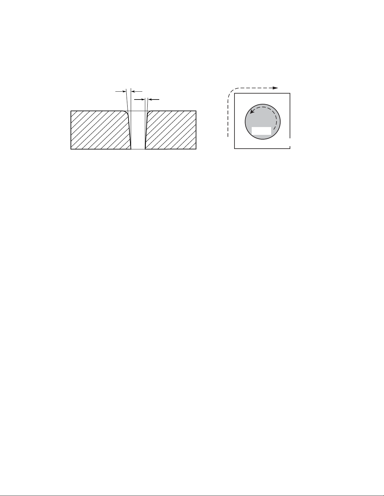
Direction of Cut
The plasma gas stream swirls as it leaves the torch to maintain a stable arc column. This swirl effect results in one
side of a cut being more square than the other. Viewed along the direction of travel, the right side of the cut is more
square than the left.
Left Side
Cut Angle
Right Side
Cut Angle
A-00512
Clockwise
Scrap
Counter-
Clockwise
Scrap
Workpiece
Art # A-04182
Side Characteristics Of Cut
To make a square - edged cut along an inside diameter of a circle, move the torch counterclockwise around the circle.
To keep the square edge along an outside diameter cut, move the torch in a clockwise direction.
Underwater Cutting
Cutting on a water table either underwater or with the water touching the plate or with a water muffler system is not
recommended. If a water table is used the water level must be a minimum of 4 inches / 100 mm from the bottom of the
plate. Failure to follow this recommendation could result in poor cut quality and short consumable parts life.
Manual 0-4730 Rev. AF 8-2 TORCH DATA
Page 3
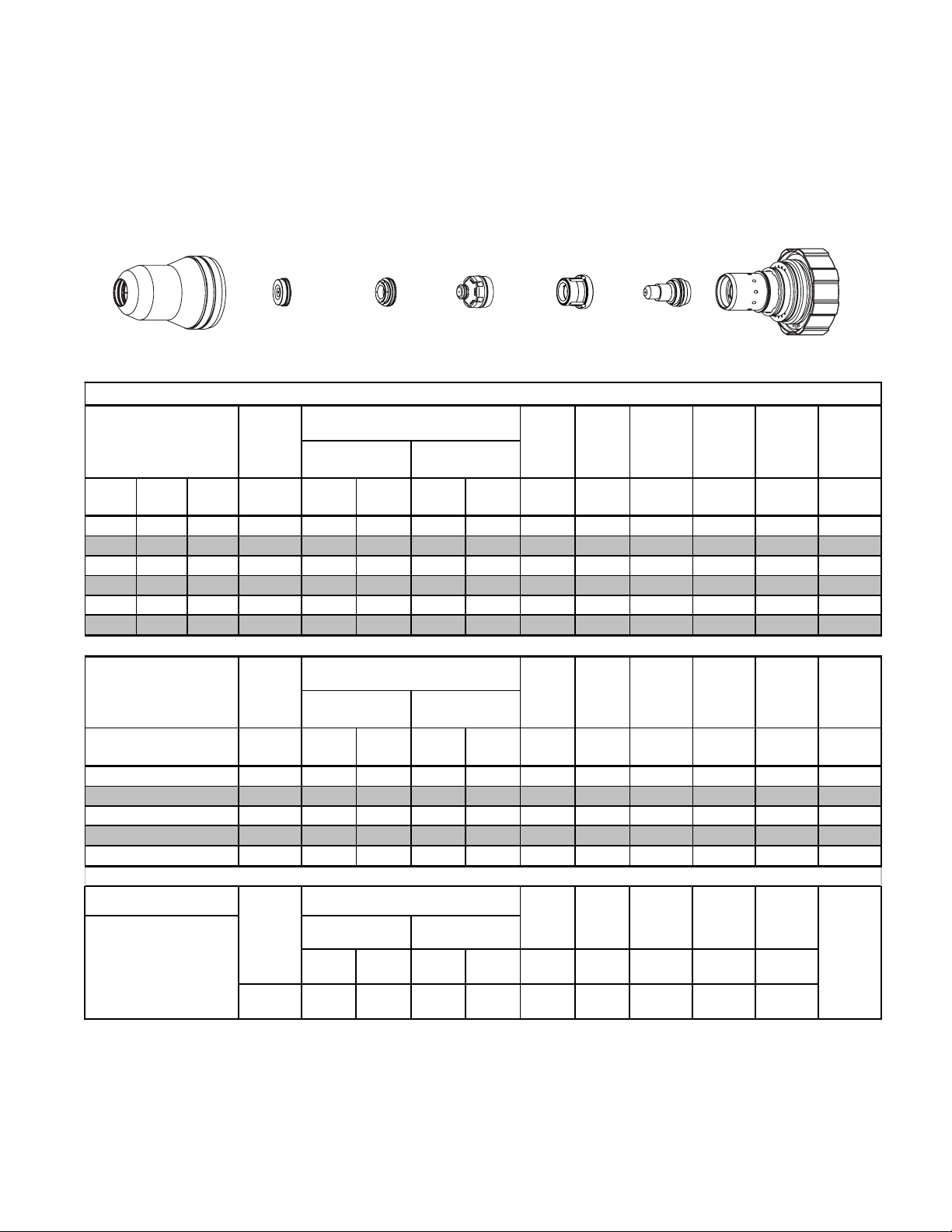
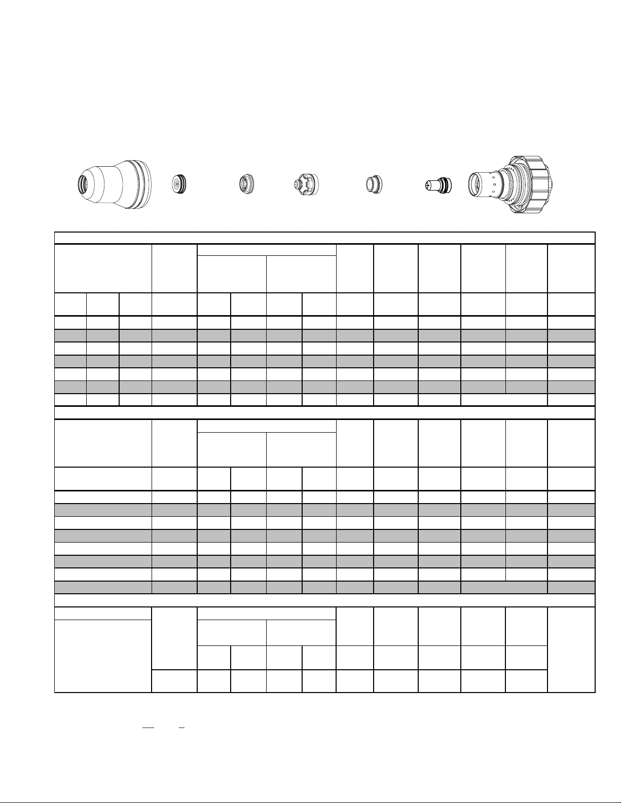
Mild Steel
30A
Plasma / O2 Shield
O
2
Shield Cup
21-1016
Shield Cap
21-1024
Shield
Gas Distributor
21-1082
Tip
21-1050
Plasma
Gas Distributor
21-1040
Electrode
21-1068
Cartridge
21-1020
Art # A-06768
30A Mild Steel (O2/O2)
Material
Thickness
Pre Flow
Pressure
(Air)
Cut Flow Rates / Pressures
Plasma (O2) Shield (O2)
Arc
Voltage
(ga) (in) inch (PSI) Ball (PSI) Ball (PSI) Volts
Torch
Working
Height
(in)
±0.005
Travel
Speed
Initial
Piercing
Height
Pierce
Delay
(ipm) (in) (sec) (in)
Kerf
Width
@ Rec.
Speed
20 0.036 60 22 120 21 120 128 0.050 130 0.120 0.2 0.058
16 0.060 60 22 120 21 120 143 0.050 60 0.120 0.3 0.070
14 0.075 60 22 120 21 120 145 0.070 45 0.120 0.3 0.072
12 0.105 60 22 120 21 120 148 0.110 40 0.150 0.3 0.074
10 0.135 80 22 120 21 120 154 0.130 30 0.150 0.3 0.085
3/16 0.188 80 22 120 21 120 154 0.120 25 0.150 0.4 0.075
Kerf
Width
@ Rec.
Speed
Material
Thickness
(mm)
1
2
3
4
5
Pre Flow
Pressure
(Air)
Cut Flow Rates / Pressures
Plasma (O2) Shield (O2)
Voltage
(Bar) Ball (Bar) Ball (Bar) Volts
Arc
Torch
Working
Height
(mm)
±0.1
Travel
Speed
(mm/min)
Initial
Piercing
Height
Pierce
Delay
(mm) (sec) (mm)
4.1 22 8.3 21 8.3 130 1.3 3050 3.0 0.2 1.5
4.1 22 8.3 21 8.3 145 1.9 1130 3.1 0.3 1.8
4.1 22 8.3 21 8.3 150 3.0 910 3.8 0.3 2.0
5.5 22 8.3 21 8.3 154 3.2 710 3.8 0.3 2.1
5.5 22 8.3 21 8.3 155 3.0 640 3.8 0.4 1.9
Marking (with 30A Mild Stee l Pa rts)
15A Arc Current
Burn-through may
occur on
thicknesses
< 1/16" (0.063") /
1.6 mm
Pre Flow
Pres sure
)
(N
2
20psi
1.4 bar
Cut Flow Rates / Pressures
Plasma
Pressure (N
Ball Press Ball P ress Volts
20
)
2
40 psi
2.8 bar
Shield
Pres sure N2)
80 psi
70
5.5 bar
Arc
Voltage
145
Torch
Working
Height
In ± 0. 005 /
mm ± 0 .1
0.1
2.5
Travel
Speed
ipm /
mm/min
300
7600
Initial
Piercing
Height
In ± 0. 005 /
mm ± 0 .1
0.1
2.5
Pierce
Delay
(sec)
0
Marking
Quality
Degrades
as
Thickness
Decreases.
Manual 0-4730 Rev. AF 8-3 TORCH DATA
Page 4

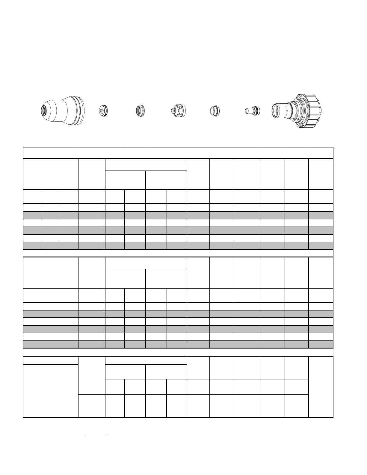
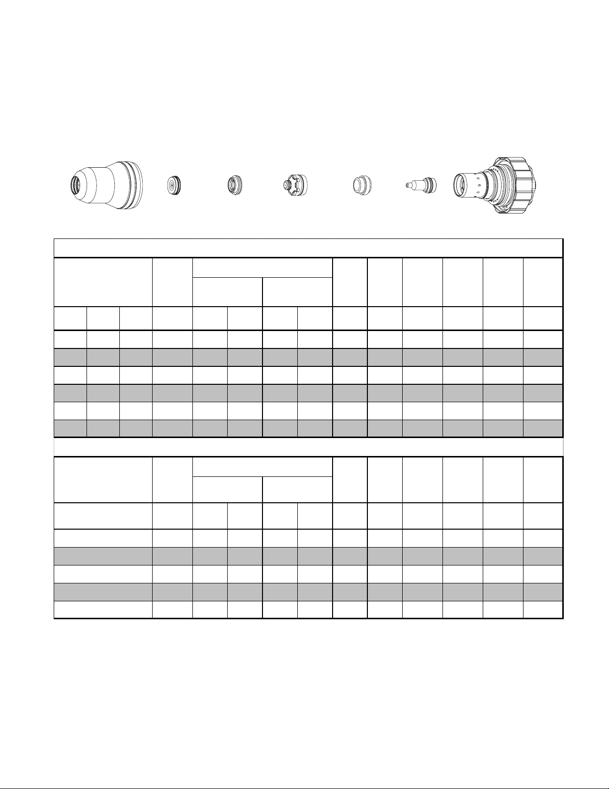
Mild Steel
Kerf
50A
Plasma / Air Shield
O
2
Shield Cup
21-1016
Shield Cap
21-1025
Material
Thickness
Pre Flow
Pressure
(Air)
(ga) (in) inch (psi) Ball (psi) Ball (psi) Volts
Shield
Gas Distributor
21-1272
Tip
21-1051
50A Mild Steel (O
Cut Flow Rates / Pressures
Plasma (O2) Shield (Air)
Plasma
Gas Distributor
21-1041
/Air)
2
Arc
Voltage
Torch
Working
Height
(in)
±0.005
Cartridge
21-1020Electrode
21-1069
Art # A-06085
Travel
Speed
Initial
Piercing
Height
Pierce
Delay
Width
@ Rec.
Speed
(ipm) (in) (sec) (in)
14 0.075 70 28 120 20 120 130 0.060 320 0.100 0.0 0.040
12 0.105 70 28 120 20 120 130 0.060 270 0.100 0.0 0.052
10 0.135 70 28 120 20 120 126 0.040 160 0.100 0.4 0.044
3/16 0.188 70 28 120 40 120 130 0.060 100 0.110 0.4 0.054
1/4 0.250 70 28 120 40 120 132 0.060 90 0.110 0.4 0.062
l
Kerf
Width
@ Rec.
Speed
Material
Thickness
(mm)
Pre Flow
Pressure
(Air)
Cut Flow Rates / Pressures
Plasma (O2)
Shield ( Air)
Voltage
(bar) Ball (bar) Ball (bar) Volts
Arc
Torch
Working
Height
(mm)
±0.1
Travel
Speed
(mm/min)
Initial
Piercing
Height
Pierce
Delay
(mm) (sec) (mm)
2
3
4
5
6
4.8 28 8.3 20 8.3 130 1.5 7970 2.5 0.0 1.1
4.8 28 8.3 20 8.3 128 1.3 5640 2.5 0.2 1.2
4.8 28 8.3 20 8.3 128 1.2 3420 2.7 0.4 1.2
4.8 28 8.3 40 8.3 130 1.5 2500 2.8 0.4 1.4
4.8 28 8.3 40 8.3 132 1.5 2340 2.8 0.4 1.5
Marking (with 50A Mild Stee l Pa rts)
18A Arc Curren t
Burn-through
may happen for
thicknesses < 1/16"
(0.063") / 1. 6 m m
Pre Flow
Pressure
(
)
N
2
20 psi
1.4 bar
Cut Flow Rates / Pressures
Plasma
Pressure (
)
N
2
Shield
P re ssure (
N
)
2
Arc
Voltage
Ball Press Ball Press Volts
40
40 ps i
2.8 bar
75
80 psi
5.5 bar
160
Torch
Working
Height
in ±0. 005 /
mm ±0.1
Travel
Speed
ipm /
mm/min
0.12 3 300
7600
Initial
Piercing
Height
in ±0. 005 /
mm ±0.1
0.12
3
Pierce
Delay
sec
0
Marking
quality
degrades
as
thickness
decreases.
Manual 0-4730 Rev. AF 8-4 TORCH DATA
Page 5
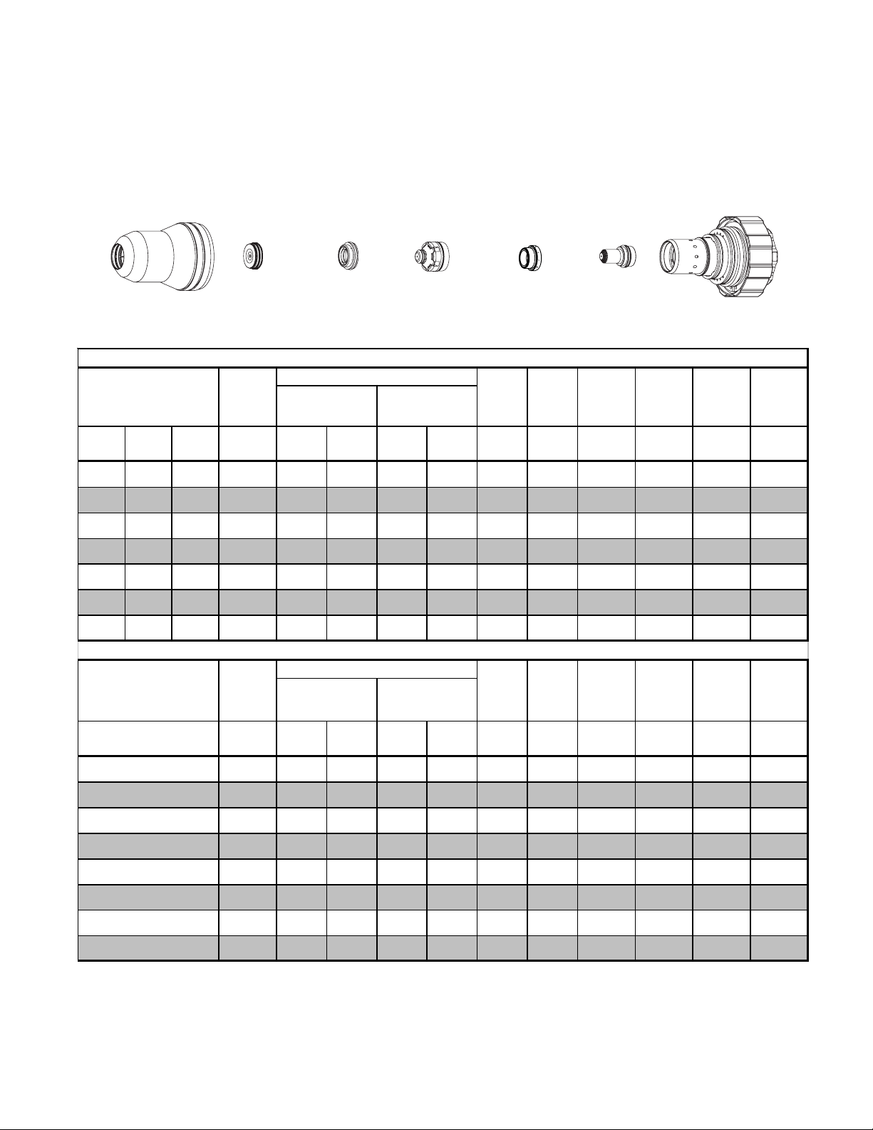
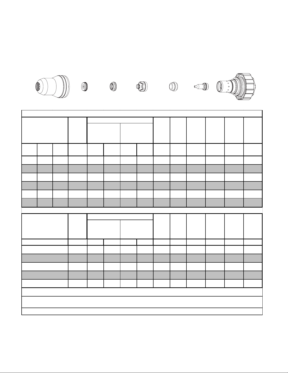
Mild Steel
70A
Plasma / Air Shield With XTL Torch Valve Assembly*
O
2
Shield Cup
21-1016
Shield Cap
21-1026
Shield
Gas Distributor
21-1272
Tip
21-1152
Plasma
Gas Distributor
21-1041
Cartridge
21-1020Electrode
21-1170
Art # A-07662
70A Mild Steel XTL (O2/Air)
Material
Thickness
(ga) (in) inch (PSI) Ball (PSI) Ball (PSI) Volts
Pre Flow
Pressure
(Air)
Cut Flow Rates / Pressures
Plasma (O2) 5Shield (Air)
Arc
Voltage
Torch
Working
Height
(in)
±0.005
Travel
Speed
(ipm) (in) (sec) (in)
Initial
Piercing
Height
Pierce
Delay
Kerf
Width
@ Rec.
Speed
16 0.060 46 35 120 41 120 138 0.070 300 0.100 0.1 0.073
14 0.075 46 35 120 41 120 138 0.070 300 0.100 0.1 0.072
12 0.105 46 55 120 60 120 142 0.080 270 0.120 0.2 0.078
10 0.135 46 55 120 60 120 142 0.080 180 0.150 0.2 0.071
3/16 0.188 46 55 120 60 120 148 0.100 130 0.200 0.4 0.077
1/4 0.250 46 55 120 60 120 148 0.100 100 0.200 0.5 0.083
Material
Thickness
(mm)
1.5
2
3
4
6
16A Arc Curren t
Burn-through
may occur
on thick nes ses
< 1/ 16" (0. 063" ) /
1.6 mm .
*XTL (eXTreme Life) Torch Valve Assembly increases the life of consumables over the original
Torch Valve Assembly. Requires Firmware version 3.2 or higher and XTL consumables.
Pre Flow
Pressure
(Air)
(Bar) Ball (Bar) Ball (Bar) Volts
Cut Flow Rates / Pressures
Plasma (O2)
Shield (Air)
Arc
Voltage
Torch
Working
Height
(mm)
±0.1
Travel
Speed
(mm/min) (mm) (sec) (mm)
Initial
Piercing
Height
Pierce
Delay
3.2 35 8.3 41 8.3 138 1 .8 7620 2.5 0.1 1.9
3.2 35 8.3 41 8.3 138 1.8 7530 2.6 0.1 1.9
3.2 55 8.3 60 8.3 142 2.0 5860 3.4 0.2 1.9
3.2 55 8.3 60 8.3 145 2.3 4030 4.4 0.3 1.9
3.2 55 8.3 60 8.3 148 2.5 3190 5.1 0.4 2.0
3.2 55 8.3 60 8.3 148 2.5 2710 5.1 0.5
Marking (with 70A Mild Stee l Pa rts)
Pre Flow
Pressure
(
)
N
2
20 ps i
1.4 bar
Cut Flow Rates / Pressures
)
Pressure (
Shield
Plasma
Pressure (
N
2
Ball Press Ball Press
50
40 psi
2.8 bar
80
80 ps i
5.5 bar
Arc
Voltage
)
N
2
Volts
155
Torch
Working
Height
in ±0. 005 /
mm ± 0 .1
0.12
3
Travel
Speed
ipm /
mm/min
300
7600
Initial
Piercing
Height
in ±0.005 /
mm ±0.1
0.12
3
Pierce
Delay
sec
0
Kerf
Width
@ Rec.
Speed
2.1
Marking
quality
degrades
as
thickness
decreases.
Manual 0-4730 Rev. AF 8-5 TORCH DATA
Page 6
Mild Steel
Kerf
p
85A
Air Plasma / Air Shield
Shield Cup
21-1016
Shield Cap
21-1027
Shield
Gas Distributor
21-1272
Tip
21-1153
Plasma
Gas Distributor
21-1041
Electrode
21-1071
Cartridge
21-1020
Art # A-04028
85A Mild Steel Air/Air
Material
Thickness
(ga) (in) inch (psi) Ball (psi) Ball (psi) Volts
Pre Flow
Pressure
(Air)
Cut Flow Rates / Pressures
Plasma (A ir) Shield (A ir)
Arc
Voltage
Torch
Working
Height
(in)
±0.005
Travel
Speed
(ipm) (in) (sec) (in)
Initial
Piercing
Height
Pierce
Delay
Width
@ Rec.
S
eed
10 0.135 74 55 120 80 120 160 0.070 240 0.200 0.0 0.062
3/16 0.188 74 55 120 80 120 161 0.090 174 0.200 0.1 0.065
1/4 0.250 74 55 120 80 120 164 0.090 140 0.200 0.2 0.065
3/8 0.375 74 55 120 80 120 175 0.170 75 0.250 0.3 0.085
1/2 0.500 74 55 120 80 120 169 0.120 64 0.300 0.3 0.081
5/8 0.625 74 55 120 80 120 178 0.140 30 0.350 0.8 0.095
3/4 0.750 74 55 120 80 120 186 0.150 25 NR NR 0.098
Material
Thickness
(mm)
4
5
6
8
10
12
15
20
Pre Flow
Pressure
(Air)
(bar) Ball (bar) Ball (bar) Volts
Cut Flow Rates / Pressures
Plasma (A ir) Shield (A ir)
Voltage
Arc
Torch
Working
Height
(mm)
±0.1
Travel
Speed
(mm/min)
5.1 55 8.3 80 8.3 160 2.0 5310 5.1 0.0 1.6
5.1 55 8.3 80 8.3 162 2.3 4240 5.1 0.1 1.7
5.1 55 8.3 80 8.3 163 2.3 3730 5.1 0.2 0.2
5.1 55 8.3 80 8.3 170 3.3 2700 5.7 0.3 1.9
5.1 55 8.3 80 8.3 174 4.1 1860 6.5 0.3 2.2
5.1 55 8.3 80 8.3 170 3.3 1690 7.3 0.3 2.1
5.1 55 8.3 80 8.3 176 3.4 1000 8.5 0.7 2.3
5.1 55 8.3 80 8.3 188 3.9 600 NR NR 2.5
Initial
Piercing
Height
(mm) (sec) (mm)
Pierce
Delay
Kerf
Width
@ Rec.
Speed
Manual 0-4730 Rev. AF 8-6 TORCH DATA
Page 7
Mild Steel
100A
Plasma / Air Shield With XTL Torch Valve Assembly*
O
2
Shield Cup
21-1016
Shield Cap
21-1027
Material
Thickness
(ga) (in) inch (PSI) Ball (PSI) Ball (PSI) V olts
10 0.135 40 55 120 80 120 138 0.070 280 0.200 0.2 0.065
3/16 0.188 40 55 120 80 120 140 0.090 190 0.200 0.2 0.070
1/4 0.250 40 55 120 80 120 141 0.100 150 0.200 0.3 0.078
3/8 0.375 40 55 120 80 120 143 0.110 95 0.250 0.4 0.085
1/2 0.500 40 55 120 80 120 147 0.120 64 0.300 0.6 0.097
5/8 0.625 40 55 120 80 120 148 0.120 50 0.350 0.8 0.100
3/4 0.750 40 55 120 80 120 157 0.150 25 0.125
Material
Thickness
Pre Flow
Pressure
(Air)
Pre Flow
Pressure
(Air)
Shield
Gas Distributor
21-1272
Cut Flow Rates / Pressures
) Shield (Air)
2
Cut Flow Rates / Pressures
Plasma (O
) Shield (Air)
2
21-1153
100A Mild Steel XTL O
Tip
Plasma
Gas Distributor
21-1041
/Air
2
Arc
Voltage
Arc
Voltage
Torch
Working
Height
(in)
±0.005
Torch
Working
Height
Electrode
21-1171
Travel
SpeedPlasma (O
(ipm) (in) (sec) (in)
Travel
Speed
Piercing
Piercing
Cartridge
21-1020
Art # A-07665
Initial
Height
Edge start Only
Initial
Height
Pierce
Delay
Pierce
Delay
Kerf Width
@ Rec.
Speed
Kerf Width
@ Rec.
Speed
(mm)
4
5
6
8
10
12
15
20
15A Arc Current
Burn-through
may occur
for thick nesses
< 1/16" (0.063") / 1.6 mm.
*XTL (eXTreme Life) Torch Valve Assembly increases the life of consumables over the original
Torch Valve Assembly. Requires Firmware version 3.2 or higher and XTL consumables.
(Bar) Ball (Bar) Ball (Bar) Volts
2.8 55 8.3 80 8.3 139 2.0 6120 5.1 0.2 1.7
2.8 55 8.3 80 8.3 140 2.3 4670 5.1 0.2 1.8
2.8 55 8.3 80 8.3 141 2.5 4030 5.1 0.3 1.9
2.8 55 8.3 80 8.3 142 2.7 3080 5.7 0.4 2.1
2.8 55 8.3 80 8.3 144 2.8 2300 6.5 0.4 2.2
2.8 55 8.3 80 8.3 146 3.0 1800 7.3 0.6 2.4
2.8 55 8.3 80 8.3 148 3.1 1370 8.5 0.7 2.5
2.8 55 8.3 80 8.3 157 3.8 640 3.2
Marking (with 100A Mild Steel Parts)
Pre Flow
Pressure
)
(
N
2
20 psi
1.4 bar
Cut Flow Rates / Pressures
Plasma
Pres sure (
Ball Press Ball P ress Volts
50
N
2
40 psi
2.8 bar
)
Shield
Pres sure (
100
N
80 psi
5.5 bar
2
)
Arc
Voltage
190
(mm)
±0.1
Torch
Working
Height
in ±0.005 /
mm ±0.1
0.12
3
(mm/min) (mm) (sec) (mm)
Edge Start Only
Travel
Speed
ipm /
mm/min
300
7600
Initial
Piercing
Height
in ±0.005 /
mm ±0.1
0.12
3
Pierce
Delay
(sec)
0
Marking
quality
degrades
as
thickness
decreases
Manual 0-4730 Rev. AF 8-7 TORCH DATA
Page 8
Stainless Steel
30A
Air Plasma / Air Shield
Shield Cup
21-1016
Shield Cap
21-1033
Shield
Gas Distributor
21-1274
Tip
21-1059
Plasma
Gas Distributor
21-1045
Cartridge
21-1020Electrode
21-1077
Art # A-04498
30A Stainless Steel (Air/Air)
Material
Thickness
(ga) (in) inch (psi) Ball (psi) Ball (psi) Volts
Pre Flow
Pressure
(Air)
Cut Flow Rates / Pressures
Plasma (A ir) Shield (A ir)
Arc
Voltage
Torch
Working
Height
(in)
±0.005
Travel
Speed
(ipm) (in) (sec) (in)
Initial
Piercing
Height
Pierce
Delay
Kerf
Width
@ Rec.
Speed
26 0.019 60 64 120 20 120 87 0.020 350 0.040 0.0 0.029
24 0.025 60 64 120 20 120 85 0.020 320 0.040 0.0 0.028
22 0.031 60 64 120 20 120 80 0.020 310 0.040 0.0 0.034
20 0.038 60 64 120 20 120 75 0.020 300 0.060 0.1 0.025
18 0.050 60 64 120 20 120 78 0.020 150 0.080 0.2 0.032
16 0.063 60 64 120 20 120 76 0.020 110 0.080 0.2 0.030
Kerf
Width
@ Rec.
Speed
Material
Thickness
(mm)
0.6
0.8
1
1.5
2
Pre Flow
Pressure
(Air)
(bar) Ball (bar) Ball (bar) Volts
Cut Flow Rates / Pressures
Plasma (A ir) Shield (A ir)
Voltage
Arc
Torch
Working
Height
(mm)
±0.1
Travel
Speed
(mm/min)
Initial
Piercing
Height
(mm) (sec) (mm)
Pierce
Delay
4.1 64 8.3 20 8.3 85 0.5 13580 1.0 0.0 0.7
4.1 64 8.3 20 8.3 80 0.5 11580 1.1 0.0 0.9
4.1 64 8.3 20 8.3 75 0.5 9780 1.6 0.1 0.7
4.1 64 8.3 20 8.3 77 0.5 5970 2.0 0.2 0.8
4.1 64 8.3 20 8.3 74 0.5 4050 2.0 0.2 0.7
Manual 0-4730 Rev. AF 8-8 TORCH DATA
Page 9
Stainless Steel
30A
Plasma / H2O Shield
N
2
Shield Cup
21-1016
Shield Cap
21-1033
Cut Flow Rates / Pressures
Material
Thickness
Pre Flow
Pressure
(N
)
2
Plasma (N
(ga) (in) (in) (psi) Ball (psi) Ball (psi) (v olts)
Shield
Gas Distributor
21-1274
30A Stainless Steel N
) S hi eld (H2O)
2
Tip
21-1059
Plasma
Gas Distributor
21-1045
O
2/H2
** A r c
Voltage
Torch
Working
Height
±0.005
(in)
Cartridge
21-1020Electrode
21-1077
Art # A-04498
Kerf
Width
@ Rec.
Speed
Travel
Speed
Initial
Piercing
Height
Pierce
Delay
(ipm) (in) (sec) (in)
26 0.019 90 75 120 4 55 91 0.020 600 0.040 0.0 0.047
24 0.025 90 64 120 4 55 97 0.020 440 0.040 0.0 0.045
22 0.031 90 50 120 4 55 95 0.020 420 0.040 0.0 0.045
20 0.038 90 60 120 5 55 105 0.020 300 0.050 0.1 0.044
18 0.050 90 60 120 5 55 78 0.030 250 0.050 0.1 0.035
16 0.063 90 60 120 5 55 85 0.050 205 0.060 0.2 0.044
Material
Thickness
(mm)
0.6
0.8
1.0
1.5
2.0
Pre Flow
Pressure
(N
Cut Flow Rates / Pressures
)
2
Plasma (N
) S hi eld (H2O)
2
** Arc
Voltage
Torch
Working
Height
(bar) Ball (bar) Ball (bar) (volts) (mm)
Travel
Speed
(mm/min)
Initial
Piercing
Height
Pierce
Delay
(mm) (sec) (mm)
6.2 75 8.3 4 3.8 96 0.5 12110 1.0 0.0 1.2
6.2 64 8.3 4 3.8 96 0.5 10450 1.0 0.0 1.1
6.2 50 8.3 4 3.8 102 0.5 7470 1.3 0.1 1.1
6.2 60 8.3 5 3.8 83 1.0 5550 1.4 0.2 1.0
6.2 60 8.3 5 3.8 93 2.0 3820 1.8 0.3 1.4
Kerf
Width
@ Rec.
Speed
Pres s ure of the wat er s upply li ne s houl d be regulated by c ust omer-s uppl ied pres sure regulator.
NOTE 1
: Ohmic height sensing is not recommended with water shield.
W at er on t he plat e i nt erferes elect ricall y wi t h t he ohm i c sens i ng c i rc ui t .
NOTE 2
: Wat er s ourc e used for H
O Wat er Shi el d m ust be demine ral i zed.
2
Manual 0-4730 Rev. AF 8-9 TORCH DATA
Page 10

Stainless Steel
50A
Air Plasma / Air Shield
Shield Cup
21-1016
Shield Cap
21-1034
Shield
Gas Distributor
21-1274
Tip
21-1060
Plasma
Gas Distributor
21-1041
Cartridge
21-1020Electrode
21-1078
Art # A-04029
50A Stainless Steel (Air/Air)
Material
Thickness
(ga) (in) inch (psi) Ball (psi) Ball (psi) Volts
Pre Flow
Pressure
(Air)
Cut Flow Rates / Pressures
Plasma (A ir) Shield (Air)
Arc
Voltage
Torch
Working
Height
(in)
±0.005
Travel
Speed
(ipm) (in) (sec) (in)
Initial
Piercing
Height
Pierce
Delay
Kerf
Width
@ Rec.
Speed
14 0.078 100 62 120 75 120 109 0.060 180 0.120 0.0 0.044
12 0.109 100 62 120 75 120 114 0.060 130 0.150 0.0 0.049
10 0.141 100 62 120 75 120 118 0.060 120 0.180 0.1 0.050
3/16 0.188 100 62 120 75 120 124 0.080 70 0.200 0.3 0.059
Material
Thickness
(mm)
1.5
2
3
4
5
Pre Flow
Pressure
(Air)
(bar) Ball (bar) Ball (bar) Volts
Cut Flow Rates / Pressures
Plasma (A ir) Shield (Air)
Voltage
Arc
Torch
Working
Height
(mm)
±0.1
Travel
Speed
(mm/min)
Initial
Piercing
Height
(mm) (sec) (mm)
Pierce
Delay
6.9 62 8.3 75 8.3 106 1.5 5350 2.6 0.0 1.0
6.9 62 8.3 75 8.3 109 1.5 4540 3.1 0.0 1.1
6.9 62 8.3 75 8.3 115 1.5 3230 4.0 0.0 1.3
6.9 62 8.3 75 8.3 120 1.7 2600 4.8 0.2 1.4
6.9 62 8.3 75 8.3 125 2.1 1520 5.2 0.3 1.5
Kerf
Width
@ Rec.
Speed
Manual 0-4730 Rev. AF 8-10 TORCH DATA
Page 11

Stainless Steel
50A
Plasma / H2O Shield
N
2
Shield Cup
21-1016
Shield Cap
21-1034
Material
Thickness
Pre Flow
Pressure
)
(N
2
(ga) (in) inch (psi) Ball (psi) Ball (psi) Volts
Shield
Gas Distributor
21-1274
Tip
21-1060
50A Stainless Steel (N
Cut Flow Rates / Pressures
Plasma (N2) Shield (H2O)
Plasma
Gas Distributor
21-1041
0)
2/H2
Arc
Voltage
Torch
Working
Height
(in)
±0.005
Cartridge
21-1020Electrode
21-1078
Art # A-04029
Travel
Speed
Initial
Piercing
Height
Pierce
Delay
Width
@ Rec.
Speed
(ipm) (in) (sec) (in)
Kerf
14 0.078 100 62 120 4 55 117 0.110 170 0.200 0.2 0.043
12 0.109 100 62 120 4 55 119 0.110 150 0.200 0.2 0.047
Kerf
Width
@ Rec.
Speed
Material
Thickness
(mm)
2
Pre Flow
Pressure
(N
2
Cut Flow Rates / Pressures
Plasma (N2) Shield (H2O)
)
Arc
Voltage
(bar) * Ball (bar) * Ball (bar) * Volts
Torch
Working
Height
(mm)
±0.1
Travel
Speed
(mm/min)
Initial
Piercing
Height
Pierce
Delay
(mm) (sec) (mm)
6.9 62 8.3 4 3.8 117 2.8 4310 5.1 0.2 1.1
3
6.9 62 8.3 4 3.8 120 2.8 3660 5.1 0.2 1.2
* Pres sure of the water s upply line should be regulat ed by cus t om er s uppl ied pres sure regulator
: Ohmic height sensing is not recommended with water shield.
NOTE
W at er on t he plat e i nt erferes elect ric al l y wit h t he ohmi c s ensing c i rc ui t.
NOTE 2
: Wat er s ourc e used for H
O Water Shield must be demineralized.
2
Manual 0-4730 Rev. AF 8-11 TORCH DATA
Page 12

Stainless Steel
Kerf
70A
Air Plasma / Air Shield
Shield Cup
21-1016
Shield Cap
21-1035
Shield
Gas Distributor
21-1274
Tip
21-1061
Plasma
Gas Distributor
21-1041
Electrode
21-1079
Cartridge
21-1020
Art # A-04341
70A Stainless Steel (Air/Air)
Material
Thickness
(ga) (in) inch (psi) Ball (psi) Ball (psi) Volts
Pre Flow
Pressure
(Air)
Cut Flow Rates / Pressures
Plasma (A ir) Shield (A ir)
Arc
Voltage
Torch
Working
Height
(in)
±0.005
Travel
Speed
(ipm) (in) (sec) (in)
Initial
Piercing
Height
Pierce
Delay
Kerf
Width
@ Rec.
Speed
10 0.141 84 41 120 94 120 138 0.080 120 0.140 0.3 0.075
3/16 0.188 84 41 120 87 120 144 0.080 100 0.140 0.4 0.082
1/4 0.250 84 41 120 72 120 148 0.130 55 0.180 0.5 0.085
3/8 0.375 84 41 120 72 120 152 0.140 40 0.200 0.6 0.083
1/2 0.500 84 53 120 60 120 160 0.140 25 0.280 0.8 0.080
Material
Thickness
(mm)
3
4
5
6
8
10
12
Pre Flow
Pressure
(Air)
(bar) Ball (bar) Ball (bar) Volts
Cut Flow Rates / Pressures
Plasma (A ir) Shield (A ir)
Voltage
Arc
Torch
Working
Height
(mm)
±0.1
Travel
Speed
(mm/min)
Initial
Piercing
Height
(mm) (sec) (mm)
Pierce
Delay
5.8 41 8.3 94 8.3 135 2.0 3300 3.6 0.3 1.8
5.8 41 8.3 94 8.3 140 2.0 2870 3.6 0.3 2.0
5.8 41 8.3 87 8.3 145 2.2 2380 3.7 0.4 2.1
5.8 41 8.3 72 8.3 148 2.3 1440 4.5 0.5 2.1
5.8 41 8.3 72 8.3 150 2.4 1200 4.8 0.6 2.1
5.8 41 8.3 72 8.3 153 3.6 960 5.4 0.6 2.1
5.8 53 8.3 60 8.3 158 3.6 720 6.7 0.8 2.1
Width
@ Rec.
Speed
Manual 0-4730 Rev. AF 8-12 TORCH DATA
Page 13

Stainless Steel
70A
Plasma / H2O Shield
N
2
Shield Cup
21-1016
Material
Thickness
(ga) (in) inch (PSI) Ball (PSI) Ball (PSI) * V olts
Shield Cap
21-1047
Pre Flow
Pressure
)
(N
2
Cut Flow Rates / Pressures
Plasma (N
Shield
Gas Distributor
21-1274
70A Sta i n l ess S te el (N
) Shield (H2O)
2
Tip
21-1064
Gas Distributor
2/H2
Arc
Voltage
10 0.141 45 55 90 5 55 146
3/16 0.188 45 55 90 5 55 150
1/4 0.250 45 55 90 5 55 159 0.150 50 0.250 0.5 0.095
3/8 0.375 45 55 90 5 55 168 0.150 35 0.250 0.7 0.103
Material
Thickness
(mm)
3
4
5
6
8
10
Pre Flow
Pressure
)
(N
2
(Bar) Ball (Bar) Ball (Bar) * Volts
3.1 55 6.2 5 3.8 142 2.5 3040 6.3 0.3 1.8
3.1 55 6.2 5 3.8 143 2.5 2780 6.3 0.3 2.0
3.1 55 6.2 5 3.8 151 2.5 2140 6.3 0.4 2.2
3.1 55 6.2 5 3.8 157 3.8 1495 6.3 0.5 2.3
3.1 55 6.2 5 3.8 164 3.8 1070 6.3 0.6 2.5
3.1 55 6.2 5 3.8 170 3.8 980 6.3 0.7 2.6
Cut Flow Rates / Pressures
Plasma (N
) Shield (H2O)
2
Arc
Voltage
* Pres sure of the water suppl y line should be regulat ed by cus t om er s uppli ed pres sure regulator
NOTE 1
: Ohmi c height sens ing i s not recomm ended wit h water shield.
W at er on the pl at e i nt erferes elect ric al l y wit h t he ohm ic s ensing c i rc ui t .
NOTE 2
: Water source used for H
O W at er S hiel d m us t be deminerali z ed.
2
Plasma
21-1041
0)
Torch
Working
Height
(in)
±0.005
0.100
0.100
Torch
Working
Height
(m m)
±0.1
Cartridge
21-1020Electrode
21-1084
Art # A-07217
Travel
Speed
(ipm) (in) (sec) (in)
Initial
Piercing
Height
Pierce
Delay
Width
@ Rec.
Speed
120 0.250 0.3 0.075
90 0.250 0.4 0.086
Travel
Speed
(mm/mi
n)
Initial
Piercing
Height
(mm) (sec) (mm)
Pierce
Delay
Width
@ Rec.
Speed
Kerf
Kerf
Manual 0-4730 Rev. AF 8-13 TORCH DATA
Page 14

Stainless Steel
100A
H35 Plasma / N
Shield Cup
21-1016
Shield
2
Shield Cap
21-1036
Shield
Gas Distributor
21-1274
Tip
21-1062
Gas Distributor
100A Stainless Steel (H35/N
Material
Thickness
(ga) (in) inch (psi) Ball (psi) Ball (psi) Volts
Pre Flow
Pressure
(N
2
Cut Flow Rates / Pressures
Plasma (H35) Shield (N2)
)
1/4 0.250 80 50 120 97 120 148 0.145 72 0.250 0.3 0.093
3/8 0.375 80 55 120 97 120 152 0.130 55 0.300 0.3 0.090
1/2 0.500 80 55 120 97 120 155 0.130 42 0.350 0.5 0.095
5/8 0.625 80 62 120 97 120 157 0.130 25 0.350 0.6 0.100
Plasma
21-1041
Arc
Voltage
)
2
Torch
Working
Height
(in)
±0.005
Cartridge
Electrode
21-1080
Travel
Speed
(ipm) (in) (sec) (in)
Piercing
Height
Initial
21-1020
Art # A-04030
Pierce
Delay
Kerf
Width
@ Rec.
Speed
Material
Thickness
(mm)
6
8
10
12
15
Pre Flow
Pressure
(N
2
(bar) Ball (bar) Ball (bar) Volts
Cut Flow Rates / Pressures
Plasma (H35) Shield (N2)
)
Voltage
Arc
Torch
Working
Height
(mm)
±0.1
Travel
Speed
(mm/min)
Initial
Piercing
Height
(mm) (sec) (mm)
Pierce
Delay
5.5 50 8.3 97 8.3 148 3.7 1880 6.2 0.3 2.0
5.5 55 8.3 97 8.3 150 3.5 1600 7.0 0.3 2.0
5.5 55 8.3 97 8.3 152 3.3 1350 7.8 0.3 1.9
5.5 62 8.3 97 8.3 154 3.3 1140 8.6 0.5 1.9
5.5 62 8.3 97 8.3 156 3.3 750 8.9 0.7 1.9
Kerf
Width
@ Rec.
Speed
Manual 0-4730 Rev. AF 8-14 TORCH DATA
Page 15

Stainless Steel
100A
Plasma / H20 Shield
N
2
Shield Cup
21-1016
Shield Cap
21-1036
Shield
Gas Distributor
21-1274
Tip
21-1053
100A Sta i n l ess Steel (N
Material
Thickness
(in) inch (PSI) Ball (PSI) Ball (PSI) * Volts
Pre Flow
Pressure
(N
Cut Flow Rates / Pressures
)
2
Plasma (N
) Shield (H2O)
2
Arc
Voltage
Plasma
Gas Distributor
21-1041
O)
2/H2
Torch
Working
Height
(in)
±0.005
Travel
Speed
(ipm) (in) (sec) (in)
Electrode
21-1089
Initial
Piercing
Height
Pierce
Delay
Cartridge
21-1020
Art # A-07214
Kerf
Width
@ Rec.
Speed
3/16 0.188 45 60 90 7 55 148 0.100 140 0.300 0.1 0.091
1/4 0.250 45 60 90 7 55 158 0.100 95 0.300 0.1 0.091
3/8 0.375 45 60 90 7 55 168 0.150 65 0.350 0.2 0.100
1/2 0.500 45 60 90 7 55 168 0.150 50 0.350 0.4 0.102
Kerf
Width
@ Rec.
Speed
Material
Thickness
(m m)
5
6
8
10
12
Pre Flow
Pressure
(N
(Bar) Ball (Bar) Ball (Bar) * Volts
Cut Flow Rates / Pressures
)
2
Plasma (N
) Shield (H2O)
2
Arc
Voltage
Torch
Working
Height
(mm)
±0.1
Travel
Speed
(mm/min) (mm) (sec) (mm)
Initial
Piercing
Height
Pierce
Delay
3.1 60 6.2 7 3.8 149 2.5 3390 7.6 0.1 2.3
3.1 60 6.2 7 3.8 156 2.5 2665 7.6 0.1 2.3
3.1 60 6.2 7 3.8 163 3.8 2015 8.9 0.2 2.5
3.1 60 6.2 7 3.8 168 3.8 1595 8.9 0.3 2.6
3.1 60 6.2 7 3.8 168 3.8 1355 8.9 0.4 2.6
* Pres sure of the water suppl y line should be regulat ed by cus t om er s uppli ed pres sure regulator
NOTE 1
: Ohmi c height sens ing i s not rec omm ended wit h wat er s hi eld.
W at er on the pl at e i nt erferes elect ric al l y wit h t he ohmi c s ensing c i rc ui t .
NOTE 2
: Water source used for H
O W at er S hiel d m us t be deminerali zed.
2
Manual 0-4730 Rev. AF 8-15 TORCH DATA
Page 16

Aluminum
30A
Air Plasma / Air Shield
Shield Cup
21-1016
Shield Cap
21-1033
Shield
Gas Distributor
21-1274
Tip
21-1059
Plasma
Gas Distributor
21-1045
Cartridge
21-1020Electrode
21-1077
Art # A-04498
30A Aluminum (Air/Air)
Material
Thickness
(ga) (in) inch (psi) Ball (psi) Ball (psi) Volts
Pre Flow
Pressure
(Air)
Cut Flow Rates / Pressures
Plasma (A ir) Shield (Air)
Arc
Voltage
Torch
Working
Height
(in)
±0.005
Travel
Speed
(ipm) (in) (sec) (in)
Initial
Piercing
Height
Pierce
Delay
Kerf
Width
@ Rec.
Speed
25 0.025 60 60 120 15 120 86 0.020 500 0.040 0.0 0.029
21 0.037 60 60 120 15 120 86 0.020 240 0.060 0.1 0.046
18 0.052 60 60 120 15 120 84 0.020 230 0.100 0.2 0.034
16 0.064 60 60 120 15 120 80 0.020 220 0.100 0.2 0.036
Kerf
Width
@ Rec.
Speed
Material
Thickness
(mm)
1
Pre Flow
Pressure
(Air)
(bar) Ball (bar) Ball (bar) Volts
Cut Flow Rates / Pressures
Plasma (A ir) Shield (Air)
Voltage
Arc
Torch
Working
Height
(mm)
±0.1
Travel
Speed
(mm/min)
Initial
Piercing
Height
(mm) (sec) (mm)
Pierce
Delay
4.1 60 8.3 15 8.3 86 0.5 6060 1.7 0.1 0.9
2
4.1 60 8.3 15 8.3 75 0.5 5280 2.5 0.2 0.9
Manual 0-4730 Rev. AF 8-16 TORCH DATA
Page 17

Aluminum
30A
Plasma / H2O Shield
N
2
Shield Cup
21-1016
Shield Cap
21-1033
Shield
Gas Distributor
21-1274
Tip
21-1059
Plasma
Gas Distributor
21-1045
Cartridge
21-1020Electrode
21-1077
Art # A-04498
30A Alumi num (N2/H2O)
Material
Thickness
(ga) (in) inch psi Ball ps i Ball psi* Volts
Pre Flow
Pressure
(N
Cut Flow Rates / Pressures
)
2
Plasma (N
)
2
Shield ( H2O)
Arc
Voltage
Torch
Working
Height
(in)
±0.005
Travel
Speed
(ipm) (in) (sec) (in)
Initial
Piercing
Height
Pierce
Delay
Kerf
Width
@ Rec.
Speed
25 0.025 96 55 120 4 55 103 0.030 230 0.080 0.0 0.034
21 0.037 96 55 120 4 55 103 0.030 220 0.080 0.1 0.045
18 0.052 96 55 120 4 55 103 0.030 150 0.080 0.2 0.031
16 0.064 96 55 120 4 55 103 0.030 110 0.080 0.2 0.036
Material
Thickness
(mm)
Bold type
Pre Flow
Pressure
(N
bar Ball bar Ball bar* Volts
1
2
6.6 55 8.3 4 3.8 103 0.8 5310 2.0 0.1 1.1
6.6 55 8.3 4 3.8 103 0.8 1550 2.0 0.2 1.0
Cut Flow Rates / Pressures
)
2
Plasma (N
)
2
Shield ( H
2
O)
Arc
Voltage
Torch
Working
Height
(m m)
±0.1
Travel
Speed
(mm/min) (mm) (sec) (mm)
Initial
Piercing
Height
Pierce
Delay
indicates maximum piercing parameters.
* Pres sure of the water suppl y li ne s hould be regulat ed by c us tomer s uppl ied pres sure regulator.
NOTE 1
: Ohmi c height sens ing i s not recomm ended wit h water shield.
Water on the plate int erferes elect ricall y wi t h t he ohm i c sens i ng c i rc ui t .
NOTE 2
: Wat er s ourc e used for H
O Wat er Shi el d m ust be demine ral i zed.
2
Kerf
Width
@ Rec.
Speed
Manual 0-4730 Rev. AF 8-17 TORCH DATA
Page 18

Aluminum
50A
Air Plasma / Air Shield
Shield Cup
21-1016
Shield Cap
21-1034
Shield
Gas Distributor
21-1274
Tip
21-1060
Plasma
Gas Distributor
21-1041
Cartridge
21-1020Electrode
21-1078
Art # A-04029
50A Aluminum (Air/Air)
Material
Thickness
(ga) (in) inch (psi) Ball (psi) Ball (psi) Volts
Pre Flow
Pressure
(Air)
Cut Flow Rates / Pressures
Plasma (A ir) Shield (Air)
Arc
Voltage
Torch
Working
Height
(in)
±0.005
Travel
Speed
(ipm) (in) (sec) (in)
Initial
Piercing
Height
Pierce
Delay
Kerf
Width
@ Rec.
Speed
16 0.064 100 60 120 75 120 124 0.100 140 0.200 0.0 0.06
12 0.097 100 60 120 75 120 125 0.105 90 0.200 0.0 0.067
11 0.120 100 60 120 75 120 129 0.110 60 0.200 0.0 0.068
3/16 0.188 100 60 120 75 120 133 0.120 40 0.200 0.2 0.074
Material
Thickness
(mm)
2
3
4
5
Pre Flow
Pressure
(Air)
(bar) Ball (bar) Ball (bar) Volts
Cut Flow Rates / Pressures
Plasma (A ir) Shield (Air)
Voltage
Arc
Torch
Working
Height
(mm)
±0.1
Travel
Speed
(mm/min)
Initial
Piercing
Height
(mm) (sec) (mm)
Pierce
Delay
6.9 60 8.3 75 8.3 124 2.6 2990 5.1 0.0 1.6
6.9 60 8.3 75 8.3 129 2.8 1520 5.1 0.0 1.7
6.9 60 8.3 75 8.3 131 2.9 1240 5.1 0.1 1.8
6.9 60 8.3 75 8.3 134 3.1 950 5.1 0.2 1.9
Kerf
Width
@ Rec.
Speed
Manual 0-4730 Rev. AF 8-18 TORCH DATA
Page 19

Aluminum
50A
Plasma / H2O Shield
N
2
Shield Cup
21-1016
Material
Thickness
(ga) (in) inch (psi) Ball (psi) Ball (psi) Volts
Shield Cap
21-1034
Pr e Flow
)
(N
2
Shield
Gas Distributor
21-1274
Tip
21-1060
50A Alum i num (N
Cut Flow Rates / Pressures
Plasma (N2) Shield (H2O)
Plasma
Gas Distributor
21-1041
O)
2/H2
Arc
Voltage
Torch
Working
Height
(in)
±0.005
Cartridge
21-1020Electrode
21-1078
Art # A-04029
Travel
Speed
(ipm) (in) (sec) (in)
Initial
Piercing
Height
Pierce
Delay
Kerf
Width
@ Rec.
Speed
16 0.064 100 60 120 4 55 120 0.11 140 0.200 0.2 0.045
12 0.097 100 60 120 4 55 120 0.11 90 0.200 0.2 0.046
11 0.120 100 60 120 4 55 123 0.11 60 0.200 0.2 0.050
3/16 0.188 100 60 120 4 55 125 0.12 40 0.200 0.2 0.051
Material
Thickness
(mm)
2
3
4
5
Pre Flow
Pressure
(N
2
(bar) * Ball (bar) * Ball (bar) * Volts
Cut Flow Rates / Pressures
Plasma (N2)
)
Shield ( H2O)
Arc
Voltage
Torch
Working
Height
(mm)
±0.1
Travel
Speed
(mm/min)
6.9 60 8.3 4 3.8 120 2.8 2990 5.1 0.2 1.2
6.9 60 8.3 4 3.8 123 2.8 1520 5.1 0.2 1.3
6.9 60 8.3 4 3.8 124 2.9 1240 5.1 0.2 1.3
6.9 60 8.3 4 3.8 125 3.1 950 5.1 0.2 1.3
Initial
Piercing
Height
(mm) (sec) (mm)
* Pres sure of the water suppl y line should be regulat ed by c ust om er s uppli ed pres sure regulator.
NOTE 1
: Ohmic height sensing is not recommended with water shield.
Water on the plate int erferes elect ricall y with t he ohmi c sens i ng circ ui t .
NOTE 2
: Wat er s ourc e used for H
O Water Shield must be demineralized.
2
Pierce
Delay
Kerf
Width
@ Rec.
Speed
Manual 0-4730 Rev. AF 8-19 TORCH DATA
Page 20

Aluminum
70A
Air Plasma / Air Shield
Shield Cup
21-1016
Shield Cap
21-1035
Shield
Gas Distributor
21-1274
Tip
21-1061
Plasma
Gas Distributor
21-1041
Electrode
21-1079
Cartridge
21-1020
Art # A-04341
70A Aluminum (Air/Air)
Material
Thickness
(ga) (in) inch (psi) Ball (psi) Ball (psi) Volts
Pre Flow
Pres sure
(Air)
Cut Flow Rates / Pressures
Plasma (Air) Shield (Air)
Arc
Voltage
Torch
Working
Height
(in)
±0.005
Travel
Speed
(ipm) (in) (sec) (in)
Initial
Piercing
Height
Pierce
Delay
Kerf
Width
@ Rec.
Speed
14 0.079 84 42 120 70 120 153 0.060 300 0.140 0.0 0.058
12 0.097 84 42 120 70 120 160 0.080 200 0.140 0.1 0.062
3/16 0.188 84 42 120 70 120 162 0.120 100 0.140 0.1 0.072
1/4 0.250 84 42 120 70 120 166 0.140 70 0.180 0.2 0.073
3/8 0.375 84 42 120 70 120 168 0.140 60 0.180 0.3 0.078
Material
Thickness
(m m)
2
3
4
5
6
8
10
Pre Flow
Pres sure
(Air)
(bar) Ball (bar) Ball (bar) Volts
Cut Flow Rates / Pressures
Plasma (Air) Shield (Air)
Voltage
Arc
Torch
Working
Height
(mm)
±0.1
Travel
Speed
(mm/min)
Initial
Piercing
Height
(mm) (sec) (mm)
Pierce
Delay
5.8 42 8.3 70 8.3 153 1.5 7620 3.6 0.0 1.5
5.8 42 8.3 70 8.3 160 2.3 4490 3.6 0.1 1.6
5.8 42 8.3 70 8.3 161 2.7 3390 3.6 0.1 1.7
5.8 42 8.3 70 8.3 163 3.1 2430 3.7 0.1 1.8
5.8 42 8.3 70 8.3 165 3.4 1950 4.4 0.2 1.9
5.8 42 8.3 70 8.3 167 3.6 1650 4.6 0.3 2.0
5.8 42 8.3 70 8.3 168 3.6 1490 4.6 0.3 2.0
Kerf
Width
@ Rec.
Speed
Manual 0-4730 Rev. AF 8-20 TORCH DATA
Page 21

Aluminum
70A
Plasma / H2O Shield
N
2
Shield Cup
21-1016
Material
Thickness
(ga) (in) inch (PSI) Ball (PSI) Ball (PSI) * Volts
Shield Cap
21-1047
Pre Flow
Pressure
)
(N
2
Cut Flow Rates / Pressures
Plasma (N
Shield
Gas Distributor
21-1274
70A Alum inum (N
) Shield (H2O)
2
Tip
21-1064
Plasma
Gas Distributor
21-1041
O)
2/H2
Arc
Voltage
Working
Torch
Height
(in)
±0.005
Cartridge
21-1020Electrode
21-1084
Art # A-07217
Travel
Speed
(ipm) (in) (sec) (in)
Initial
Piercing
Height
Pierce
Delay
Kerf
Width
@ Rec.
Speed
16 0.064 45 55 90 5 55 155 0.100 300 0.250 0.0 0.057
14 0.079 45 55 90 5 55 148 0.100 240 0.250 0.0 0.068
12 0.097 45 55 90 5 55 150 0.150 200 0.250 0.1 0.095
3/16 0.188 45 55 90 5 55 150 0.150 120 0.250 0.3 0.095
1/4 0.250 45 55 90 5 55 158 0.150 70 0.250 0.3 0.097
3/8 0.375 45 55 90 5 55 162 0.150 35 0.250 0.5 0.100
Material
Thickness
(mm)
2
3
4
5
6
8
10
Pre Flow
Pressure
(N
(Bar) Ball (Bar) Ball (Bar) * Volts
Cut Flow Rates / Pressures
)
2
Plasma (N
) Shield (H2O)
2
Arc
Voltage
Torch
Working
Height
(mm)
±0.1
3.1 55 6.2 5 3.8 148 2.5 6100 6.3 0.0 1.7
3.1 55 6.2 5 3.8 150 3.8 4610 6.3 0.2 2.4
3.1 55 6.2 5 3.8 150 3.8 3730 6.3 0.3 2.4
3.1 55 6.2 5 3.8 151 3.8 2870 6.3 0.3 2.4
3.1 55 6.2 5 3.8 156 3.8 2060 6.3 0.3 2.5
3.1 55 6.2 5 3.8 160 3.8 1315 6.3 0.4 2.6
3.1 55 6.2 5 3.8 163 3.8 880 6.3 0.5 2.7
Travel
Speed
(m m/min) (mm) (sec) (mm)
Initial
Piercing
Height
* Pres sure of the water suppl y line should be regulat ed by c ust om er s uppli ed pres sure regulator
NOTE 1
: Ohmi c height sens i ng is not rec omm ended wit h wat er s hi eld.
W at er on the pl at e i nt erferes elect ric al l y wit h t he ohmi c s ensing c i rc ui t .
NOTE 2
: Water source used for H
O W at er S hiel d m us t be deminerali z ed.
2
Pierce
Delay
Kerf
Width
@ Rec.
Speed
Manual 0-4730 Rev. AF 8-21 TORCH DATA
Page 22

Aluminum
100A
H35 Plasma / N
Shield Cup
21-1016
Shield
2
Shield Cap
21-1036
Shield
Gas Distributor
21-1274
Tip
21-1062
100A Aluminu m (H35/ N
Material
Thickness
Pre Flow
Pressure
(N
2
(ga) (in) inch (psi) Ball (psi) Ball (psi) Volts
Cut Flow Rates / Pressures
Plasma (H35) Shield (N2)
)
3/8 0.375 80 67 120 62 120 152 0.154 60 0.350 0.2 0.105
1/2 0.500 80 67 120 62 120 158 0.150 50 0.350 0.2 0.110
5/8 0.625 80 67 120 62 120 160 0.150 35 0.350 0.5 0.110
Plasma
Gas Distributor
21-1041
)
2
Arc
Voltage
Torch
Working
Height
(in)
±0.005
Cartridge
Electrode
21-1020
21-1080
Art # A-04030
Travel
Speed
Initial
Piercing
Height
Pierce
Delay
@ Rec.
(ipm) (in) (sec) (in)
Kerf
Width
Speed
Material
Thickness
(mm)
10
12
15
Pre Flow
Pressure
(N
2
Cut Flow Rates / Pressures
Plasma (H35) Shield (N2)
)
Voltage
(bar) Ball (bar) Ball (bar) Volts
Arc
Torch
Working
Height
(mm)
±0.1
Travel
Speed
(mm/min)
Initial
Piercing
Height
Pierce
Delay
(mm) (sec) (mm)
5.5 67 8.3 62 8.3 153 3.9 1490 8.9 0.2 2.7
5.5 67 8.3 62 8.3 157 3.8 1330 8.9 0.2 2.8
5.5 67 8.3 62 8.3 159 3.8 990 8.9 0.5 2.8
Kerf
Width
@ Rec.
Speed
Manual 0-4730 Rev. AF 8-22 TORCH DATA
Page 23

Aluminum
100A
Plasma / H2O Shield
N
2
Shield Cup
21-1016
Shield Cap
21-1036
Shield
Gas Distributor
21-1274
Tip
21-1053
100A Aluminum (N
Material
Thickness
(in) inch (PSI) Ball (PSI) Ball (PSI) * Volts
Pre Flow
Pressure
(N
Cut Flow Rates / Pressures
)
Plasma (N
2
2
) Shield (H2O)
Arc
Voltage
Plasma
Gas Distributor
21-1041
O)
2/H2
Torch
Working
Height
(in)
±0.005
Electrode
21-1089
Travel
Speed
(ipm) (in) (sec) (in)
Initial
Piercing
Height
Cartridge
21-1020
Art # A-07214
Pierce
Delay
Kerf
Width
@ Rec.
Speed
3/16 0.188 45 60 90 7 55 158 0.150 130 0.300 0.1 0.095
1/4 0.250 45 60 90 7 55 160 0.150 90 0.300 0.1 0.100
3/8 0.375 45 60 90 7 55 161 0.150 70 0.300 0.2 0.100
1/2 0.500 45 60 90 7 55 171 0.150 40 0.300 0.4 0.100
5/8 0.625 45 60 90 7 55 175 0.180 35 0.350 0.5 0.105
Kerf
Width
@ Rec.
Speed
Material
Thickness
(mm)
5
6
8
10
12
15
Pre Flow
Pressure
(N
(Bar) Ball (Bar) Ball (Bar) * V olts
Cut Flow Rates / Pressures
Plasma (N
)
2
2
) Shield (H2O)
Arc
Voltage
Torch
Working
Height
(m m)
±0.1
Travel
Speed
(mm/min) (mm) (sec) (mm)
Initial
Piercing
Height
Pierce
Delay
3.1 60 6.2 7 3.8 158 3.8 3150 7.6 0.1 2.4
3.1 60 6.2 7 3.8 160 3.8 2510 7.6 0.1 2.5
3.1 60 6.2 7 3.8 161 3.8 2025 7.6 0.2 2.5
3.1 60 6.2 7 3.8 162 3.8 1665 7.6 0.3 2.5
3.1 60 6.2 7 3.8 169 3.8 1190 7.6 0.4 2.5
3.1 60 6.2 7 3.8 174 4.6 925 8.9 0.5 2.7
* Pres sure of the water s upply li ne s hould be regulated by cus t om er supplied pres sure regulator
NOTE 1
: Ohm ic height sens i ng is not rec om mended with water s hi eld.
W at er on t he plat e i nt erferes elect ricall y with t he ohmi c s ens i ng circ ui t .
NOTE 2
: Wat er s ourc e used for H
O Water Shi eld m ust be demi neralized.
2
Manual 0-4730 Rev. AF 8-23 TORCH DATA
Page 24

TORCH PARTS LIST
Returns
If a product must be returned for service, contact your authorized distributor. Materials returned without proper authorization will not be accepted.
Ordering Information
Order replacement parts by catalog number and complete description of the part or assembly. Also include the
model and serial number of the machine or torch.
Refer to parts diagrams within the body of the manual for consumable parts and replacement O-Ring catalog numbers.
Description Catalog Number
O-Ring Lubricant (Christo-Lube MCG-129) 9-4893
Torch Head and Cartridge O-Ring Kit 9-9488
Shield Cup (all applications except 200A & 300A) 21-1016
Torch Cartridge (includes Cartridge Tool) (all applications except 200A & 300A) 21-1020
Cartridge Tool 9-9431
Cartridge Retaining Ring 9-9489
Inner O-Ring (Cat. No. 8-0545)
Location (Under Locking Ring)
Cartridge Retaining
Ring 9-9489
Snap Ring
O-Ring, Cat. No. 8-0544
O-Ring, Cat. No. 8-0540
Cartridge Assembly
Art # A-07087
O-Rings
Cat. No. 9-9041
Cat. No. 8-0539
Cat. No. 8-3487
Cat. No. 8-0530
Coolant Tube Kit
9-9429
Torch Head
Art # A-07088
Manual 0-4730 Rev. AF 8-24 TORCH DATA
Page 25

Torch Replacement Parts
Description Catalog Number
Torch Head Assembly 21-1002
Coolant Check Valve Assembly 9-4846
Torch Clamp Assembly 9-9336
Torch Positioning Tube (includes hardware kit 9-4847) 9-4700
Positioning Tube Hardware Kit (O-Ring & screws) 9-4847
Plasma & Shield Leads Assembly (to Torch Valve) 4-3026
Ohmic Clip (not shown) 9-9414
Coolant Supply,
Coolant Return,
Torch Leads End Cap
Torch Clamp
Leads Cover
and Pilot Leads
To Remote Arc Starter
Positioning Tube
Torch Head
O-Ring
Coolant
Check Valve
Coolant Tube Assembly
Shield Gas
To Torch Valve
Plasma Gas
Art # A-07423
Manual 0-4730 Rev. AF 8-25 TORCH DATA
Page 26
Art # A-07424
Shield Retainer
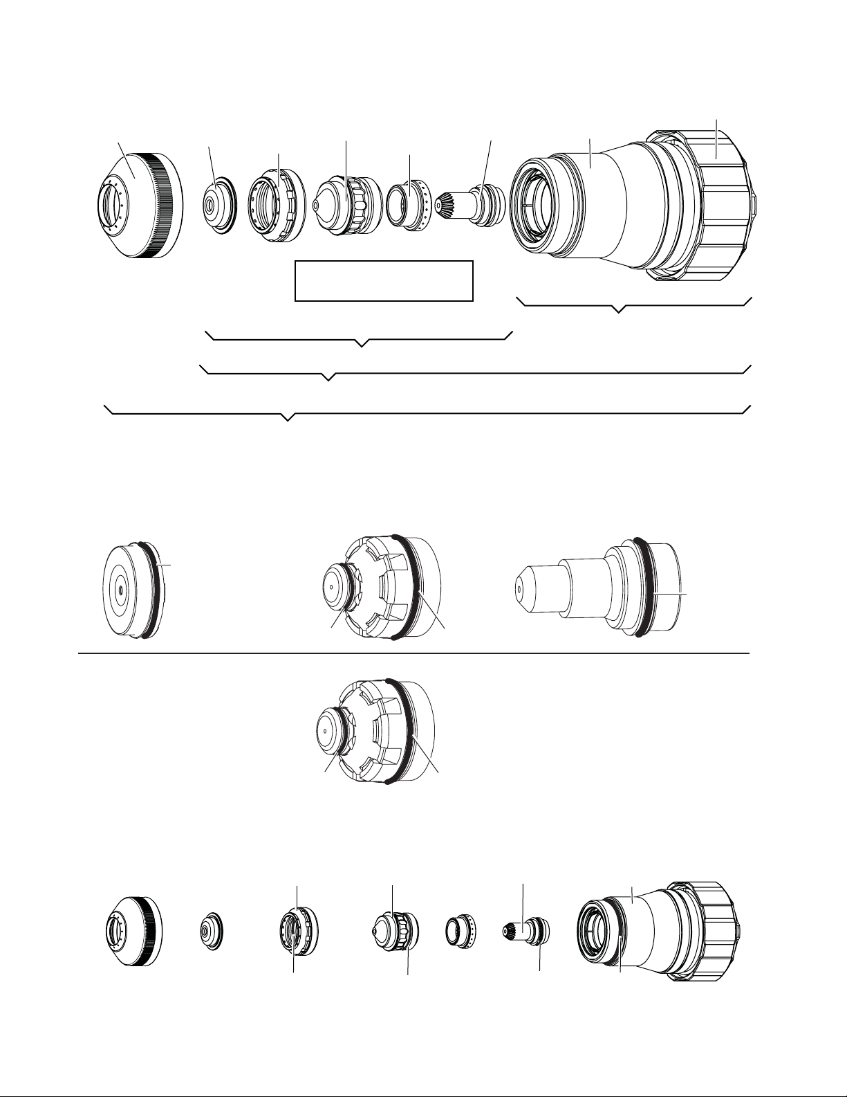
Assembly Sequence, 300 Amp Consumables
Shield Cap
Shield Gas
Distributor
Tip
Plasma Gas
Distributor
Electrode
Shield Cup
Assembly sequence:
2
3
4
Consumables O-Rings (up to 150 Amps)
Cartridge
1
Shield Cap Tips Up to 100 Amps Electrode
O-Ring 9-9039
O-Ring 9-9061
150 Amp Tip
O-Ring 9-9038
O-Ring 9-9060
O-Ring 9-9060
Consumables O-Rings (300 Amps)
Art # A-07419
Shield Gas Distributor
Tip
Electrode
O-Ring 9-9035
Art # A-07161
Shield Cup
O-Ring
9-9060
O-Ring
9-9060
O-Ring
9-9035
O-Ring
8-0558
Manual 0-4730 Rev. AF 8-26 TORCH DATA
Page 27

PATENT INFORMATION
XTTM-300 Plasma Cutting Torch Patents
The following parts are covered under U.S. and Foreign Patents as follows:
Catalog # Description Patent(s)
21-1002 Torch Head U.S. Pat No(s) 6,946,616; 6,919,526; 6,852,944;
7,071,443 and 7,019,254
21-1016 Shield Cup US Pat No(s) 6946616; 6919526; 6989505
Other Pat(s) Pending
21-1020 Cartridge US Pat No(s) 6946616; 6919526; 6989505
Other Pat(s) Pending
21-1024 Shield Cap US Pat No(s) 6946616; 6919526; 6989505;
D525043; 7071443 Other Pat(s) Pending
21-1025 Shield Cap US Pat No(s) 6946616; 6919526; 6989505;
D525043; 7071443 Other Pat(s) Pending
21-1026 Shield Cap US Pat No(s) 6946616; 6919526; 6989505;
D525043; 7071443 Other Pat(s) Pending
21-1027 Shield Cap US Pat No(s) 6946616; 6919526; 6989505;
D525043; 7071443 Other Pat(s) Pending
21-1028 Shield Cap US Pat No(s) 6946616; 6919526; 6989505;
D525043; 7071443 Other Pat(s) Pending
21-1033 Shield Cap US Pat No(s) 6946616; 6919526; 6989505;
D525043; 7071443 Other Pat(s) Pending
21-1034 Shield Cap US Pat No(s) 6946616; 6919526; 6989505;
D525043; 7071443 Other Pat(s) Pending
21-1035 Shield Cap US Pat No(s) 6946616; 6919526; 6989505;
D525043; 7071443 Other Pat(s) Pending
21-1036 Shield Cap US Pat No(s) 6946616; 6919526; 6989505;
D525043; 7071443 Other Pat(s) Pending
21-1047 Shield US Pat No(s) 6946616; 6919526; 6989505;
D525043; 7071443 Other Pat(s) Pending
21-1048 Shield US Pat No(s) 6946616; 6919526; 6989505;
D525043; 7071443 Other Pat(s) Pending
21-1275 Shield Cap US Pat No(s) 6946616; 6919526; 6989505; D523042;
7071443 Other Pat(s) Pending
21-1040 Plasma Gas Distributor US Pat No(s) 6946616; 6919526; 6989505
Other Pat(s) Pending
21-1041 Plasma Gas Distributor US Pat No(s) 6946616; 6919526; 6989505
Other Pat(s) Pending
21-1045 Plasma Gas Distributor US Pat No(s) 6946616; 6919526; 6989505
Other Pat(s) Pending
21-1050 Tip US Pat No(s) 6946616; 6919526; 6989505;
7005600; D519135; D524,336 Other Pat(s) Pending
21-1051 Tip US Pat No(s) 6946616; 6919526; 6989505;
7005600; D519135; D524,336 Other Pat(s) Pending
21-1052 Tip US Pat No(s) 6946616; 6919526; 6989505;
7005600; D519135; D524,336 Other Pat(s) Pending
21-1053 Tip US Pat No(s) 6946616; 6919526; 6989505;
7005600; D519135; D524,336 Other Pat(s) Pending
21-1054 Tip US Pat No(s) 6946616; 6919526; 6989505;
7005600; D519135; D524,336 Other Pat(s) Pending
21-1059 Tip US Pat No(s) 6946616; 6919526; 6989505; 7005600;
D519135; D524,336 Other Pat(s) Pending
21-1060 Tip US Pat No(s) 6946616; 6919526; 6989505; 7005600;
D519135; D524,336 Other Pat(s) Pending
Manual 0-4730 Rev. AF 8-27 TORCH DATA
Page 28

TM
XT-300
Plasma Cutting Torch Patents Continued
The following parts are covered under U.S. and Foreign Patents as follows:
Catalog # Description Patent(s)
21-1061 Tip US Pat No(s) 6946616; 6919526; 6989505; 7005600;
D519135; D524,336 Other Pat(s) Pending
21-1062 Tip US Pat No(s) 6946616; 6919526; 6989505; 7005600;
D519135; D524,336 Other Pat(s) Pending
21-1152 Tip US Pat No(s) 6946616; 6919526; 6989505; 7005600;
D519135; D524,336 Other Pat(s) Pending
21-1153 Tip US Pat No(s) 6946616; 6919526; 6989505; 7005600;
D519135; D524,336 Other Pat(s) Pending
21-1092 Tip US Pat No(s) 6946616; 6919526; 6989505;
7005600; D519135; D524,336 Other Pat(s) Pending
21-1068 Electrode US Pat No(s) 6946616; 6919526; 6989505; 6998566;
D517577 Other Pat(s) Pending
21-1069 Electrode US Pat No(s) 6946616; 6919526; 6989505; 6998566
Other Pat(s) Pending
21-1070 Electrode US Pat No(s) 6946616; 6919526; 6989505; 6998566;
D517576 Other Pat(s) Pending
21-1071 Electrode US Pat No(s) 6946616; 6919526; 6989505; 6998566;
D517576 Other Pat(s) Pending
21-1072 Electrode US Pat No(s) 6946616; 6919526; 6989505; 6998566;
D517576 Other Pat(s) Pending
21-1077 Electrode US Pat No(s) 6946616; 6919526; 6989505; 6998566
Other Pat(s) Pending
21-1078 Electrode US Pat No(s) 6946616; 6919526; D505963; 6989505;
6998566 Other Pat(s) Pending
21-1079 Electrode US Pat No(s) 6946616; 6919526; 6989505; 6998566
Other Pat(s) Pending
21-1080 Electrode US Pat No(s) 6946616; 6919526; 6989505; 6998566;
D517577 Other Pat(s) Pending
21-1170 Electrode US Pat No(s) 6946616; 6919526; 6989505; 6998566;
Other Pat(s) Pending
21-1171 Electrode US Pat No(s) 6946616; 6919526; 6989505; 6998566;
D517577 Other Pat(s) Pending
21-1082 Shield Gas Distributor US Pat No(s) 6946616; 6919526; 6989505
Other Pat(s) Pending
21-1272 Shield Gas Distributor US Pat No(s) 6946616; 6919526; 6989505
Other Pat(s) Pending
21-1273 Shield Gas Distributor US Pat No(s) 6946616; 6919526; 6989505
Other Pat(s) Pending
21-1274 Shield Gas Distributor US Pat No(s) 6946616; 6919526; 6989505
Other Pat(s) Pending
The following parts are licensed under U.S. Patent No. 5,120,930 and 5,132,512:
Catalog Number Description
21-1027 Shield Cap
21-1275 Shield Cap
NOTE
This manual may refer to some or all of the parts listed.
Manual 0-4730 Rev. AF 8-28 TORCH DATA
 Loading...