

Page 1

Plasma Cutting
System
Thermal Arc T A 500
Instruction Manual
August 7, 2001 Manual No. 0-0470
Page 2

Page 3

WARNINGS
Read and understand this entire Manual and your employer’s safety practices before installing, operating, or servicing the equipment.
While the information contained in this Manual represents the Manufacturer's best judgement, the
Manufacturer assumes no liability for its use.
Plasma Cutting System T A 500
Instruction Manual Number 0-0470
Published by:
Thermal Dynamics Corporation
82 Benning Street
West Lebanon, New Hampshire, USA 03784
(603) 298-5711
Copyright 1984 by
Thermal Dynamics Corporation
www .thermal-dynamics.com
All rights reserved.
Reproduction of this work, in whole or in part, without written permission of
the publisher is prohibited.
The publisher does not assume and hereby disclaims any liability to
any party for any loss or damage caused by any error or omission in
this Manual, whether such error results from negligence, accident, or
any other cause.
Printed in the United States of America
Publication Date: August 7, 2001
Record the following information for Warranty purposes:
Where Purchased:_________________________________________
Purchase Date:____________________________________________
Power Supply Serial #:_____________________________________
Torch Serial #:_____________________________________________
Page 4

Contents
GENERAL INFORMA TION ............................................................................................................. i
Notes, Cautions and Warnings ................................................................................. i
Important Safety Precautions.................................................................................... i
Publications..............................................................................................................ii
Note, Attention et Avertissement.............................................................................. iii
Precautions De Securite Importantes.......................................................................iii
Documents De Reference ......................................................................................... v
Declaration of Conformity ........................................................................................ vii
St atement of Warranty............................................................................................viii
SECTION 1: DESCRIPTION OF EQUIPMENT........................................................................... 1-1
1.1 General Information....................................................................................... 1-1
1.2 Specifications ............................................................................................... 1-1
1.3 Plasma......................................................................................................... 1-3
1.4 Theory of Operation ...................................................................................... 1-3
SECTION 2: INST ALLA TION...................................................................................................... 2-1
2.1 Unpacking New Equipment........................................................................... 2-1
2.2 Equipment Installation .................................................................................. 2-1
SECTION 3: OPERA TION ......................................................................................................... 3-1
3.1 Operating Controls........................................................................................ 3-1
3.2 Pre-Operation Set-up .................................................................................... 3-3
3.3 Operation...................................................................................................... 3-3
3.4 Cutting and S peed Selection......................................................................... 3-5
SECTION 4: SERVICE.............................................................................................................. 4-1
4.1 T orch Maintenance........................................................................................ 4-1
4.2 T AC 500 Power Supply Maintenance ............................................................ 4-3
4.3 HE 200 Coolant Recirculator Maintenance.................................................... 4-3
4.4 Gas Pressure Regulators.............................................................................. 4-4
4.5 Troubleshooting Guide .................................................................................. 4-6
4.6 Returns......................................................................................................... 4-6
4.7 Primary V olt age Selection............................................................................. 4-6
4.8 Trouble-Shooting........................................................................................... 4-6
4.9 Test Procedures............................................................................................ 4-9
Page 5

SECTION 5: P ARTS LISTS ........................................................................................................ 5-1
5.1 System Components .................................................................................... 5-2
5.2 Front Panel Components .............................................................................. 5-4
5.3 Rear Panel Components............................................................................... 5-6
5.4 Right Side Components ................................................................................ 5-7
5.5 Left Side Components .................................................................................. 5-8
5.6 Equipment Board Assembly.......................................................................... 5-9
5.7 Bridge Assemblies .......................................................................................5-10
5.8 Bridge Assemblies....................................................................................... 5-11
5.9 Supply Console Components.......................................................................5-12
5.10 M200 T orch Components .............................................................................5-14
5.1 1 Operator Control Panel ................................................................................5-16
5.12 Gas Pressure Regulators.............................................................................5-17
APPENDIX 1 ............................................................................................................................... 1
APPENDIX 2 ................................................................................................................................2
APPENDIX 3 ................................................................................................................................3
APPENDIX 4 ................................................................................................................................4
APPENDIX 5 ............................................................................................................................... 5
APPENDIX 6 ................................................................................................................................6
APPENDIX 7 ................................................................................................................................8
Page 6

TA500 Power Supply
H
R
E200 Coolant
ecirculator
Supply Console
Operator Control Panel
M200 T orch
with Arc Starter
Page 7

GENERAL INFORMATION
GASES AND FUMES
Notes, Cautions and Warnings
Throughout this manual, notes, cautions, and warnings
are used to highlight important information. These highlights are categorized as follows:
NOTE
An operation, procedure, or backgr ound information which requires additional emphasis or is helpful in efficient operation of the system.
CAUTION
A procedure which, if not properly followed, may
cause damage to the equipment.
WARNING
A procedure which, if not properly followed, may
cause injury to the operator or others in the operating area.
Important Safety Precautions
WARNINGS
OPERATION AND MAINTENANCE OF
PLASMA ARC EQUIPMENT CAN BE DANGEROUS AND HAZARDOUS TO YOUR
HEALTH.
Plasma arc cutting produces intense electric and
magnetic emissions that may interfere with the
proper function of cardiac pacemakers, hearing
aids, or other electronic health equipment. Persons who work near plasma arc cutting applications should consult their medical health professional and the manufacturer of the health
equipment to determine whether a hazard exists.
Gases and fumes produced during the plasma cutting
process can be dangerous and hazardous to your health.
• Keep all fumes and gases from the breathing area.
Keep your head out of the welding fume plume.
• Use an air-supplied respirator if ventilation is not
adequate to remove all fumes and gases.
• The kinds of fumes and gases from the plasma arc
depend on the kind of metal being used, coatings
on the metal, and the different pr ocesses. Y ou must
be very careful when cutting or welding any metals which may contain one or more of the following:
Antimony Chromium Mercury
Arsenic Cobalt Nickel
Barium Copper Selenium
Beryllium Lead Silver
Cadmium Manganese Vanadium
• Always read the Material Safety Data Sheets
(MSDS) that should be supplied with the material
you are using. These MSDSs will give you the information regarding the kind and amount of fumes
and gases that may be dangerous to your health.
• For information on how to test for fumes and gases
in your workplace, refer to item 1 in Publications
in this manual.
• Use special equipment, such as water or down draft
cutting tables, to capture fumes and gases.
• Do not use the plasma torch in an area where combustible or explosive gases or materials are located.
• Phosgene, a toxic gas, is generated from the vapors
of chlorinated solvents and cleansers. Remove all
sources of these vapors.
• This product, when used for welding or cutting,
produces fumes or gases which contain chemicals
known to the State of California to cause birth defects and, in some cases, cancer . (California Health
& Safety Code Sec. 25249.5 et seq.)
ELECTRIC SHOCK
To prevent possible injury, read, understand and
follow all warnings, safety precautions and instructions before using the equipment. Call 1-603298-5711 or your local distributor if you have any
questions.
Date: May 1, 2000 (SPECIAL) i General Information
Electric Shock can injure or kill. The plasma arc process
uses and produces high voltage electrical energy. This
electric energy can cause severe or fatal shock to the operator or others in the workplace.
• Never touch any parts that are electrically “live”
or “hot.”
Page 8

• Wear dry gloves and clothing. Insulate yourself
from the work piece or other parts of the welding
circuit.
• Repair or replace all worn or damaged parts.
• Extra care must be taken when the workplace is
moist or damp.
• Install and maintain equipment according to NEC
code, refer to item 9 in Publications.
• Disconnect power source before performing any
service or repairs.
• Read and follow all the instructions in the Operating Manual.
FIRE AND EXPLOSION
Fire and explosion can be caused by hot slag, sparks, or
the plasma arc.
• Be sure there is no combustible or flammable material in the workplace. Any material that cannot
be removed must be protected.
• Ventilate all flammable or explosive vapors from
the workplace.
• Do not cut or weld on containers that may have
held combustibles.
• Provide a fire watch when working in an area where
fire hazards may exist.
• Hydrogen gas may be formed and trapped under
aluminum workpieces when they are cut underwater or while using a water table. DO NOT cut
aluminum alloys underwater or on a water table
unless the hydrogen gas can be eliminated or dissipated. T rapped hydrogen gas that is ignited will
cause an explosion.
NOISE
PLASMA ARC RAYS
Plasma Arc Rays can injure your eyes and burn your skin.
The plasma arc process produces very bright ultra violet
and infra red light. These arc rays will damage your
eyes and burn your skin if you are not properly pr otected.
• To protect your eyes, always wear a welding helmet or shield. Also always wear safety glasses with
side shields, goggles or other protective eye wear.
• Wear welding gloves and suitable clothing to protect your skin from the arc rays and sparks.
• Keep helmet and safety glasses in good condition.
Replace lenses when cracked, chipped or dirty.
• Protect others in the work area from the arc rays.
Use protective booths, screens or shields.
• Use the shade of lens as suggested in the following
per ANSI/ASC Z49.1:
Minimum Protective Suggested
Arc Current Shade No. Shade No.
Less Than 300* 8 9
300 - 400* 9 12
400 - 800* 10 14
* These values apply where the actual arc is clearly
seen. Experience has shown that lighter filters
may be used when the arc is hidden by the workpiece.
Publications
Refer to the following standards or their latest revisions
for more information:
1. OSHA, SAFETY AND HEAL TH STANDARDS, 29CFR
1910, obtainable from the Superintendent of Documents, U.S. Government Printing Office, Washington,
D.C. 20402
Noise can cause permanent hearing loss. Plasma arc processes can cause noise levels to exceed safe limits. You
must protect your ears from loud noise to prevent permanent loss of hearing.
• T o protect your hearing from loud noise, wear pr otective ear plugs and/or ear muffs. Protect others
in the workplace.
• Noise levels should be measured to be sure the decibels (sound) do not exceed safe levels.
• For information on how to test for noise, see item 1
in Publications in this manual.
2. ANSI Standard Z49.1, SAFETY IN WELDING AND
CUTTING, obtainable from the American Welding Society, 550 N.W. LeJeune Rd, Miami, FL 33126
3. NIOSH, SAFETY AND HEALTH IN ARC WELDING
AND GAS WELDING AND CUTTING, obtainable
from the Superintendent of Documents, U.S. Government Printing Office, Washington, D.C. 20402
4. ANSI Standard Z87.1, SAFE PRACTICES FOR OCCUP ATION AND EDUCA TIONAL EYE AND FACE PROTECTION, obtainable from American National Standards Institute, 1430 Broadway, New York, NY 10018
5. ANSI Standard Z41.1, STANDARD FOR MEN’S
SAFETY -TOE FOOTWEAR, obtainable from the American National Standards Institute, 1430 Broadway, New
York, NY 10018
General Information ii Date: May 1, 2000 (SPECIAL)
Page 9

6. ANSI Standard Z49.2, FIRE PREVENTION IN THE USE
OF CUTTING AND WELDING PROCESSES, obtainable from American National Standards Institute, 1430
Broadway, New York, NY 10018
7. AWS Standar d A6.0, WELDING AND CUTTING CONTAINERS WHICH HAVE HELD COMBUSTIBLES, obtainable from American Welding Society, 550 N.W.
LeJeune Rd, Miami, FL 33126
8. NFPA Standard 51, OXYGEN-FUEL GAS SYSTEMS
FOR WELDING, CUTTING AND ALLIED PROCESSES, obtainable from the National Fire Protection
Association, Batterymarch Park, Quincy, MA 02269
9. NFPA Standard 70, NATIONAL ELECTRICAL CODE,
obtainable from the National Fire Protection Association, Batterymarch Park, Quincy, MA 02269
10. NFP A Standard 51B, CUTTING AND WELDING PROCESSES, obtainable from the National Fire Protection
Association, Batterymarch Park, Quincy, MA 02269
11. CGA Pamphlet P-1, SAFE HANDLING OF COMPRESSED GASES IN CYLINDERS, obtainable from the
Compressed Gas Association, 1235 Jefferson Davis
Highway, Suite 501, Arlington, VA 22202
12. CSA Standard W117.2, CODE FOR SAFETY IN WELDING AND CUTTING, obtainable from the Canadian
Standards Association, Standards Sales, 178 Rexdale
Boulevard, Rexdale, Ontario, Canada M9W 1R3
13. NWSA booklet, WELDING SAFETY BIBLIOGRAPHY
obtainable from the National Welding Supply Association, 1900 Arch Street, Philadelphia, PA 19103
14. American Welding Society Standar d A WSF4.1, RECOMMENDED SAFE PRACTICES FOR THE PREPARATION FOR WELDING AND CUTTING OF CONT AINERS AND PIPING THAT HAVE HELD HAZARDOUS
SUBSTANCES, obtainable fr om the American Welding
Society, 550 N.W. LeJeune Rd, Miami, FL 33126
15. ANSI Standard Z88.2, PRACTICE FOR RESPIRA TORY
PROTECTION, obtainable from American National
Standards Institute, 1430 Broadway, New York, NY
10018
Note, Attention et Avertissement
ATTENTION
Toute procédure pouvant résulter
l’endommagement du matériel en cas de nonrespect de la procédur e en question.
AVERTISSEMENT
Toute procédure pouvant provoquer des blessures
de l’opérateur ou des autres personnes se trouvant
dans la zone de travail en cas de non-respect de la
procédure en question.
Precautions De Securite Importantes
AVERTISSEMENTS
L’OPÉRATION ET LA MAINTENANCE DU
MATÉRIEL DE SOUDAGE À L’ARC AU JET
DE PLASMA PEUVENT PRÉSENTER DES
RISQUES ET DES DANGERS DE SANTÉ.
Coupant à l’arc au jet de plasma produit de l’énergie
électrique haute tension et des émissions
magnétique qui peuvent interférer la fonction
propre d’un “pacemaker” cardiaque, les appareils
auditif, ou autre matériel de santé electronique.
Ceux qui travail près d’une application à l’arc au
jet de plasma devrait consulter leur membre
professionel de médication et le manufacturier de
matériel de santé pour déterminer s’il existe des
risques de santé.
Il faut communiquer aux opérateurs et au personnel TOUS les dangers possibles. Afin d’éviter les
blessures possibles, lisez, comprenez et suivez tous
les avertissements, toutes les précautions de sécurité
et toutes les consignes avant d’utiliser le matériel.
Composez le + 603-298-5711 ou votr e distributeur
local si vous avez des questions.
Dans ce manuel, les mots “note,” “attention,” et
“avertissement” sont utilisés pour mettre en relief des
informations à caractère important. Ces mises en relief
FUMÉE et GAZ
sont classifiées comme suit :
La fumée et les gaz produits par le procédé de jet de
NOTE
Toute opération, procédure ou renseignement
général sur lequel il importe d’insister davantage
ou qui contribue à l’efficacité de fonctionnement
du système.
plasma peuvent présenter des risques et des dangers de
santé.
• Eloignez toute fumée et gaz de votre zone de respiration. Gardez votre tête hors de la plume de fumée
provenant du chalumeau.
Date: May 1, 2000 (SPECIAL) iii General Information
Page 10

• Utilisez un appareil respiratoire à alimentation en air
si l’aération fournie ne permet pas d’éliminer la fumée
et les gaz.
• Les sortes de gaz et de fumée provenant de l’arc de
plasma dépendent du genre de métal utilisé, des
revêtements se trouvant sur le métal et des différ ents
procédés. Vous devez prendre soin lorsque vous
coupez ou soudez tout métal pouvant contenir un ou
plusieurs des éléments suivants:
antimoine cadmium mercure
argent chrome nickel
arsenic cobalt plomb
baryum cuivre sélénium
béryllium manganèse vanadium
• Lisez toujours les fiches de données sur la sécurité
des matières (sigle américain “MSDS”); celles-ci
devraient être fournies avec le matériel que vous
utilisez. Les MSDS contiennent des renseignements
quant à la quantité et la nature de la fumée et des gaz
pouvant poser des dangers de santé.
• Pour des informations sur la manière de tester la
fumée et les gaz de votre lieu de travail, consultez
l
’article 1 et les documents cités.
• Utilisez un équipement spécial tel que des tables de
coupe à débit d’eau ou à courant descendant pour
capter la fumée et les gaz.
• N’utilisez pas le chalumeau au jet de plasma dans une
zone où se trouvent des matières ou des gaz combustibles ou explosifs.
• Le phosgène, un gaz toxique, est généré par la fumée
provenant des solvants et des produits de nettoyage
chlorés. Eliminez toute source de telle fumée.
• Réparez ou remplacez toute pièce usée ou
endommagée.
• Prenez des soins particuliers lorsque la zone de travail est humide ou moite.
• Montez et maintenez le matériel conformément au
Code électrique national des Etats-Unis. (Voir l'article 9.)
• Débranchez l’alimentation électrique avant tout travail d’entretien ou de réparation.
• Lisez et respectez toutes les consignes du Manuel de
consignes.
INCENDIE ET EXPLOSION
Les incendies et les explosions peuvent résulter des scories
chaudes, des étincelles ou de l’arc de plasma. Le procédé
à l’arc de plasma produit du métal, des étincelles, des
scories chaudes pouvant mettre le feu aux matières combustibles ou provoquer l’explosion de fumées
inflammables.
• Soyez certain qu’aucune matière combustible ou inflammable ne se trouve sur le lieu de travail. Protégez
toute telle matière qu’il est impossible de retirer de la
zone de travail.
• Procurez une bonne aération de toutes les fumées
inflammables ou explosives.
• Ne coupez pas et ne soudez pas les conteneurs ayant
pu renfermer des matières combustibles.
• Prévoyez une veille d’incendie lors de tout travail dans
une zone présentant des dangers d’incendie.
• Ce produit, dans le procéder de soudage et de coupe,
produit de la fumée ou des gaz pouvant contenir des
éléments reconnu dans L’ état de la Californie, qui
peuvent causer des défauts de naissance et le cancer .
(La sécurité de santé en Californie et la code sécurité
Sec. 25249.5 et seq.)
CHOC ELECTRIQUE
Les chocs électriques peuvent blesser ou même tuer. Le
procédé au jet de plasma requiert et produit de l’éner gie
électrique haute tension. Cette énergie électrique peut
produire des chocs graves, voire mortels, pour l’opérateur
et les autres personnes sur le lieu de travail.
• Ne touchez jamais une pièce “sous tension” ou “vive”;
portez des gants et des vêtements secs. Isolez-vous
de la pièce de travail ou des autres parties du circuit
de soudage.
General Information iv Date: May 1, 2000 (SPECIAL)
• Le gas hydrogène peut se former ou s’accumuler sous
les pièces de travail en aluminium lorsqu’elles sont
coupées sous l’eau ou sur une table d’eau. NE PAS
couper les alliages en aluminium sous l’eau ou sur
une table d’eau à moins que le gas hydrogène peut
s’échapper ou se dissiper . Le gas hydrogène accumulé
explosera si enflammé.
RAYONS D’ARC DE PLASMA
Les rayons provenant de l’arc de plasma peuvent blesser
vos yeux et brûler votre peau. Le procédé à l’arc de
plasma produit une lumière infra-rouge et des rayons
ultra-violets très forts. Ces rayons d’arc nuiront à vos
yeux et brûleront votre peau si vous ne vous protégez
pas correctement.
Page 11

• Pour protéger vos yeux, portez toujours un casque ou
un écran de soudeur . Portez toujours des lunettes de
sécurité munies de parois latérales ou des lunettes de
protection ou une autre sorte de protection oculair e.
• Portez des gants de soudeur et un vêtement protecteur
approprié pour protéger votre peau contre les
étincelles et les rayons de l’arc.
• Maintenez votre casque et vos lunettes de protection
en bon état. Remplacez toute lentille sale ou
comportant fissure ou rognure.
• Protégez les autres personnes se trouvant sur la zone
de travail contre les rayons de l’arc en fournissant des
cabines ou des écrans de protection.
• Utilisez la nuance de lentille qui est suggèrée dans le
recommendation qui suivent ANSI/ASC Z49.1:
Nuance Minimum Nuance Suggerée
Courant Arc Protective Numéro Numéro
Moins de 300* 8 9
300 - 400* 9 12
400 - 800* 10 14
* Ces valeurs s’appliquent ou l’arc actuel est observé
clairement. L ’experience a démontrer que les filtres
moins foncés peuvent être utilisés quand l’arc est
caché par moiceau de travail.
BRUIT
Le bruit peut provoquer une perte permanente de l’ouïe.
Les procédés de soudage à l’arc de plasma peuvent
provoquer des niveaux sonores supérieurs aux limites
normalement acceptables. V ous dú4ez vous pr otéger les
oreilles contre les bruits forts afin d’éviter une perte
permanente de l’ouïe.
• Pour protéger votre ouïe contre les bruits forts, portez
des tampons protecteurs et/ou des protections
auriculaires. Protégez également les autres personnes
se trouvant sur le lieu de travail.
• Il faut mesurer les niveaux sonores afin d’assurer que
les décibels (le bruit) ne dépassent pas les niveaux
sûrs.
• Pour des renseignements sur la manière de tester le
bruit, consultez l’article 1, page v.
Documents De Reference
1. OSHA, NORMES DE SÉCURITÉ DU TRA VAIL ET DE
PROTECTION DE LA SANTÉ, 29CFR 1910,
disponible auprès du Superintendent of Documents,
U.S. Government Printing Office, Washington, D.C.
20402
2. Norme ANSI Z49.1, LA SÉCURITÉ DES
OPÉRATIONS DE COUPE ET DE SOUDAGE,
disponible auprès de la Société Américaine de
Soudage (American Welding Society), 550 N.W.
LeJeune Rd., Miami, FL 33126
3. NIOSH, LA SÉCURITÉ ET LA SANTÉ LORS DES
OPÉRATIONS DE COUPE ET DE SOUDAGE À
L’ARC ET AU GAZ, disponible auprès du Superintendent of Documents, U.S. Government Printing
Office, Washington, D.C. 20402
4. Norme ANSI Z87.1, PRATIQUES SURES POUR LA
PROTECTION DES YEUX ET DU VISAGE AU TRAV AIL ET DANS LES ECOLES, disponible de l’Institut
Américain des Normes Nationales (American National Standards Institute), 1430 Broadway, New Y ork,
NY 10018
5. Norme ANSI Z41.1, NORMES POUR LES
CHAUSSURES PROTECTRICES, disponible auprès
de l’American National Standards Institute, 1430
Broadway, New York, NY 10018
6. Norme ANSI Z49.2, PRÉVENTION DES INCENDIES
LORS DE L ’EMPLOI DE PROCÉDÉS DE COUPE ET
DE SOUDAGE, disponible auprès de l’American National Standards Institute, 1430 Broadway, New Y ork,
NY 10018
7. Norme A6.0 de l’Association Américaine du Soudage
(AWS), LE SOUDAGE ET LA COUPE DE
CONTENEURS A YANT RENFERMÉ DES PRODUITS
COMBUSTIBLES, disponible auprès de la American
Welding Society, 550 N.W. LeJeune Rd., Miami, FL
33126
8. Norme 51 de l’Association Américaine pour la Protection contre les Incendies (NFPA), LES SYSTEMES
À GAZ AVEC ALIMENTATION EN OXYGENE
POUR LE SOUDAGE, LA COUPE ET LES
PROCÉDÉS ASSOCIÉS, disponible auprès de la National Fire Protection Association, Batterymar ch Park,
Quincy, MA 02269
9. Norme 70 de la NFPA, CODE ELECTRIQUE NATIONAL, disponible auprès de la National Fire Protection Association, Batterymarch Park, Quincy, MA
02269
Consultez les normes suivantes ou les révisions les plus
récentes ayant été faites à celles-ci pour de plus amples
renseignements :
10. Norme 51B de la NFPA, LES PROCÉDÉS DE COUPE
ET DE SOUDAGE, disponible auprès de la National
Fire Protection Association, Batterymarch Park,
Quincy, MA 02269
Date: May 1, 2000 (SPECIAL) v General Information
Page 12

11. Brochure GCA P-1, LA MANIPULATION SANS
RISQUE DES GAZ COMPRIMÉS EN CYLINDRES,
disponible auprès de l’Association des Gaz
Comprimés (Compressed Gas Association), 1235
Jefferson Davis Highway, Suite 501, Arlington, VA
22202
12. Norme CSA W117.2, CODE DE SÉCURITÉ POUR
LE SOUDAGE ET LA COUPE, disponible auprès
de l’Association des Normes Canadiennes, Standards Sales, 178 Rexdale Boulevard, Rexdale,
Ontario, Canada, M9W 1R3
13. Livret NWSA, BIBLIOGRAPHIE SUR LA
SÉCURITÉ DU SOUDAGE, disponible auprès de
l’Association Nationale de Fournitures de Soudage
(National Welding Supply Association), 1900 Arch
Street, Philadelphia, PA 19103
14. Norme AWSF4.1 de l’Association Américaine de
Soudage, RECOMMANDATIONS DE PRATIQUES
SURES POUR LA PRÉPARATION À LA COUPE ET
AU SOUDAGE DE CONTENEURS ET TUYAUX
AYANT RENFERMÉ DES PRODUITS
DANGEREUX , disponible auprès de la American
Welding Society, 550 N.W. LeJeune Rd., Miami, FL
33126
15. Norme ANSI Z88.2, PRA TIQUES DE PROTECTION
RESPIRATOIRE, disponible auprès de l’American
National Standards Institute, 1430 Broadway, New
York, NY 10018
General Information vi Date: May 1, 2000 (SPECIAL)
Page 13

Declaration of Conformity
Manufacturer: Thermal Dynamics Corporation
Address: Industrial Park #2
W est Lebanon, New Hampshire 03784
USA
The equipment described in this manual conforms to all applicable aspects and regulations of the ‘Low Voltage Directive’ (European Council Directive 73/23/EEC as amended by Council Directive 93/68/EEC) and to the National
legislation for the enforcement of this Directive.
Serial numbers are unique with each individual piece of equipment and details description, parts used to manufacture
a unit and date of manufacture.
National Standard and Technical Specifications
The product is designed and manufactured to a number of standards and technical r equirements among them are:
* CSA (Canadian Standards Association) standard C22.2 number 60 for Arc welding equipment.
* UL (Underwriters Laboratory) rating 94VO flammability testing for all printed-circuit boar ds used.
* ISO/IEC 60974-1 (BS 638-PT10) (EN 60 974-1) (EN50192) (EN50078) applicable to plasma cutting equipment and associ-
ated accessories.
* Extensive product design verification is conducted at the manufacturing facility as part of the routine design and
manufacturing process. This is to ensure the product is safe, when used according to instructions in this manual and
related industry standards, and performs as specified. Rigorous testing is incorporated into the manufacturing
process to ensure the manufactured pr oduct meets or exceeds all design specifications.
Thermal Dynamics has been manufacturing products for more than 30 years, and will continue to achieve excellence in our
area of manufacture.
Manufacturers responsible repr esentative: Giorgio Bassi
Managing Director
Thermal Dynamics Europe
Via rio Fabbiani 8A
40067 Rastignano (BO)
Italy
Date: May 1, 2000 (SPECIAL) vii General Information
Page 14

Statement of Warranty
LIMITED WARRANTY: Thermal Dynamics® Corporation (hereinafter “Thermal”) warrants that its products will be free of defects in
workmanship or material. Should any failure to conform to this warranty appear within the time period applicable to the Thermal
products as stated below , Thermal shall, upon notification thereof and substantiation that the product has been stor ed, installed, operated,
and maintained in accordance with Thermal’s specifications, instructions, recommendations and recognized standard industry practice,
and not subject to misuse, repair , neglect, alteration, or accident, corr ect such defects by suitable r epair or replacement, at Thermal’s sole
option, of any components or parts of the product determined by Thermal to be defective.
THIS WARRANTY IS EXCLUSIVE AND IS IN LIEU OF ANY WARRANTY OF MERCHANTABILITY OR FITNESS FOR A
PAR TICULAR PURPOSE.
LIMITATION OF LIABILITY: Thermal shall not under any circumstances be liable for special or consequential damages, such as, but
not limited to, damage or loss of purchased or replacement goods, or claims of customers of distributor (hereinafter “Purchaser”) for
service interruption. The remedies of the Purchaser set forth herein are exclusive and the liability of Thermal with respect to any
contract, or anything done in connection therewith such as the performance or breach thereof, or from the manufacture, sale, delivery,
resale, or use of any goods covered by or furnished by Thermal whether arising out of contract, negligence, strict tort, or under any
warranty, or otherwise, shall not, except as expressly provided her ein, exceed the price of the goods upon which such liability is based.
THIS WARRANTY BECOMES INVALID IF REPLACEMENT PARTS OR ACCESSORIES ARE USED WHICH MAY IMPAIR THE
SAFETY OR PERFORMANCE OF ANY THERMAL PRODUCT.
THIS WARRANTY IS INVALID IF THE PRODUCT IS SOLD BY NON-AUTHORIZED PERSONS.
The limited warranty periods for Thermal products shall be as follows (with the exception of XL Plus Series, CutMaster Series , Cougar
and DRAG-GUN): A maximum of three (3) years from date of sale to an authorized distributor and a maximum of two (2) years from
date of sale by such distributor to the Purchaser, and with the further limitations on such two (2) year period (see chart below).
The limited warranty period for XL Plus Series and CutMaster Series shall be as follows: A maximum of four (4) years from date
of sale to an authorized distributor and a maximum of three (3) years from date of sale by such distributor to the Purchaser, and
with the further limitations on such three (3) year period (see chart below).
The limited warranty period for Cougar and DRAG-GUN shall be as follows: A maximum of two (2) years from date of sale to an
authorized distributor and a maximum of one (1) year from date of sale by such distributor to the Purchaser, and with the further
limitations on such two (2) year period (see chart below).
Parts
XL Plus & Parts Parts
PAK Units, Power Supplies CutMaster Series Cougar/Drag-Gun All Others Labor
Main Power Magnetics 3 Years 1 Year 2 Years 1 Year
Original Main Power Rectifier 3 Years 1 Year 2 Years 1 Year
Control PC Board 3 Years 1 Year 2 Years 1 Year
All Other Circuits And Components Including, 1 Year 1 Year 1 Year 1 Year
But Not Limited To, Starting Circuit,
Contactors, Relays, Solenoids, Pumps,
Power Switching Semi-Conductors
Consoles, Control Equipment, Heat 1 Year 1 Year 1 Y ear
Exchanges, And Accessory Equipment
Torch And Leads
Maximizer 300 Torch 1 Year 1 Y ear
PCH/M-62 & PCH/M-102 Torches 1 Year 1 Year
All Other Torches 180 Days 180 Days 180 Days 180 Days
Repair/Replacement Parts 90 Days 90 Days 90 Days None
Warranty repairs or replacement claims under this limited warranty must be submitted by an authorized Thermal Dynamics® repair
facility within thirty (30) days of the repair. No transportation costs of any kind will be paid under this warranty. Transportation
charges to send products to an authorized warranty repair facility shall be the responsibility of the customer. All returned goods shall
be at the customer’s risk and expense. This warranty supersedes all previous Thermal warranties.
Effective May 1, 2000
General Information viii Date: May 1, 2000 (SPECIAL)
Page 15

SECTION 1: DESCRIPTION
"
.
0
n
1.2 Specifications
OF EQUIPMENT
1.1 General Information
A . 500 Amp System
A complete 500 amp T A500 system includes:
• M200 machine mounted torch with either 15, 25, 35
or 50 foot (4.6, 7.6, 10.7 or 15.2 meter) leads.
• Introductory spare parts kit for torch.
• Thermal Arc T AC 500 Power Supply .
• Pilot Arc Starter.
• Supply Console for gas and water connections
and power manifolding.
• Operator Control Panel (with or without enclosure) that contains all switches, controls and
indicator lights necessary to direct system functions.
• HE 200 Coolant Recirculator, a closed loop system that recirculates, deionizes and cools the
torch coolant.
• Gas Regulators for assuring constant working
pressure regardless of variation in inlet pressure.
• Supply hoses and cables to interconnect all components in lengths required for the particular
installation. This must be decided prior to ordering the system. Refer to CC65 catalog C500 for
ordering details.
B. 1000 Amp System
A complete 1000 amp T A500 system consists of the same
components as the 500 amp system plus an additional T AC
500 Power Supply (connected in parallel with another T AC
500), an 8 foot long parallel control cable, two negative power
cables and two positive work cables.
C. Options
• A Hi-Flow Water Shield Assembly to reduce
smoke, noise and glare.
• Torch Standoff Control that automatically sets
and maintains the torch a fixed distance above
the metal being cut.
A. M200 Torch
• Current Rating: 1000 amperes maximum, General Purpose, DCSP; 750 amperes maximum, W ater Shield,
DCSP.
• General Purpose: Cutting of most metals up to
a maximum thickness of 4” (100 mm), piercing
up to 2” (50 mm).
• Water Shielding: Cutting of most metals up to a
maximum thickness of 3” (76 mm), piercing up
to 1-1/2” (38 mm).
• Weight: 7.5 lbs (3.4 kg), without leads.
13.625" Max.
6.525" Min.
.937" Ø
16.0"
M200 Torch Dimensions
• Gas Requirements:
Setting Consumptio
Plasma Gas
Se conda ry Gas
Ar/H
, or Comp. Air
2
Se conda ry Gas
: N2
: CO
: H
2
O
2
60 psi
(4.1 ba r)
,
60 psi
(4.1 ba r)
15 gph
(56 lph)
110 scfh
(52 lpm)
350 scfh
(165 lpm)
15 gph
(56 lph)
B. Thermal Arc 500 Power Supply
• Power Input: 150 KV A, 50/60 Hertz, 3 phase in
one of the following standard voltage/amperage combinations:
1-230/460 volts, 360/180 amps
2-460/575 volts, 180/145 amps
3-220/380 volts, 375/215 amps
• Rated Output: 500 amperes DC straight polarity at 200 volts
• Current Control: 150 to 500 amps continuously
adjusted by a feedback circuit
2.25
O.D
• Control Circuit: 24 volt
• Weight: 1500 lbs. (680 kg)
Manual No 0-0470 1-1 General Information
Page 16

"
)
(
D. HE 200 Coolant Recirculator
)
(
• Power Input: 50 or 60 Hz, 3 phase in one of the following standard voltage/amperage combinations:
1- 230 volts, 60 Hz, 5.5 amps
2- 460 volts, 60 Hz, 2.75 amps
3- 575 volts, 60 Hz, 2.2 amps
• Pump Capacity: 5.2 gpm (23.6 lpm)
47"
(119.4 cm)
42"
(106.7 cm)
32"
(81.3 cm)
TAC 500 Dimensions
C. Supply Console
• Power Input: From 500 Power Supply
• Plasma and Secondary Gas Pressure: Controlled by
pressure regulator at gas supply
• Secondary Water Flow: Controlled by a flow meter
on front panel
• Capacity: 80,000 BTU/hr
• Weight: 263 lbs. (1 19.4 kg)
38-1/2"
(98 cm)
HE 200 Dimensions
E. Control Panel
• Power Input: from 500 Power Supply
• Weight: 15 lbs (6.8 kg)
26"
(66 cm
28"
(71 cm)
• T orch Coolant: From HE 200 Coolant Recirculator
• Weight: 50 lbs. (22.7 kg)
9-5/8"
24.4 cm)
9-3/4
(25 cm
19"
48 cm)
Supply Console Dimensions
16-5/8"
(42.2 cm)
8-1/4"
(21 cm)
Control Panel Dimensions
General Information 1-2 Manual No 0-0470
Page 17

1.3 Plasma
1.4 Theory of Operation
Plasma is a gas which has been heated to an extremely
high temperature and ionized so that the gas becomes
electrically conductive. The plasma cutting process uses
this plasma to transfer an electric arc to the workpiece.
The metal to be cut is melted by the heat of the arc and
then blown away.
In a plasma torch, a cool gas such as nitrogen (N2) enters in
Zone A. In Zone B a pilot ar c between the electrode and the
front of the torch heats and ionizes the gas. An arc transfers
to the workpiece through a column of plasma gas in Zone C.
_
Power
Supply
A
+
B
Workpiece
C
Plasma Torch
By forcing the plasma gas and electric arc through a small
orifice, torches deliver a high concentration of heat to a very
small area. The stiff, constricted plasma arc is shown in Zone
C. Direct current straight polarity is used for plasma cutting,
as shown in the illustration.
The exclusive Dual-Flow design of cutting torches uses a
secondary gas. The secondary gas assists the high velocity
plasma in blowing the molten metal out of the cut, resulting in
fast clean, dross (slag)-free cuts. CO2, supplied from cylinders, or water , from the plant water system, is normally used
as the secondary . Compressed air may be used as the secondary gas for some applications.
A-00002
The main components of the T A500 cutting system are illustrated in the block diagram and their function is summarized
below .
Plasma and Secondary Gases
Plasma and secondary gases flow through the Control
Console to the cutting torch at pressures set at the external regulators. The pressure of each gas is indicated
on the gages mounted on the front of the Supply Console. Solenoid valves in the Supply Console turn the
gases on and off and receive their signals from the
Power Supply relay logic P.C. Board. The gas pressure
interlocks shut the system down if the plasma gas pressure falls below 40 psi.
The plasma gas flows to the torch through the black
lead, around the electrode and out thr ough the tip orifice.
The secondary gas (or water) flows to the torch through
the yellow lead, through the outer insulator, inner tip
retainer and end piece and out around the plasma arc.
Pilot Arc/Arc Starter
When the ST AR T button is pr essed the main contactor
is activated. After two seconds the pilot contactor
closes. The pilot bridge rectifier converts single-phase
AC power from the main transformer Arc Starter winding to DC for the pilot arc. At the same time the arc
starter circuit starts a series of high-voltage pulses.
These pulses jump the gap between the electrode and
the tip in the torch, which starts the pilot arc. The pilot
arc then runs for half a cycle (1/120 sec) when the voltage drops and the pilot goes out until another pulse
from the arc starter cir cuit starts it again. The arc starter
circuit provides 15 pulses per second which results in a
rapid-fire ‘pop pop pop’ pilot arc. This pilot arc makes
a path for transferring the main arc to the work.
Cutting Arc
The main bridge rectifier converts the 3-phase AC
power to DC for the main cutting arc. The negative
output is connected to the electrode through the green
torch lead. The positive output is connected to the
workpiece (through the work cable).
Manual No 0-0470 1-3 General Information
Page 18

Current Control
The desired cutting current is set with the control knob, located to the left of the ammeter, on the Contr ol panel. A
control circuit in the Power Supply stabilizes the cutting current against fluctuations due to changes in line voltages,
material thickness, torch standoff and travel speed. Changing the saturating current in the reactor changes the amount
of AC power supplied to the main bridge rectifier . The saturating current is controlled by SCR’s which ar e in turn controlled by a printed circuit card which compares the actual
cutting current to the current selector potentiometer setting.
Coolant Recirculator
When the Power Supply is turned on the Coolant
Recirculator starts circulating coolant through the tor ch
and back to the Recirculator through the radiators, reservoir, filter and pump. The Recirculator is a closed
loop system and includes a deionizer assembly which
maintains the resistivity of the coolant.
General Information 1-4 Manual No 0-0470
Page 19

System Block Diagram
Manual No 0-0470 1-5 General Information
Page 20

General Information 1-6 Manual No 0-0470
Page 21

SECTION 2:
INSTALLATION
2.1 Unpacking New Equipment
The T A-500 is skid mounted and protected with a carton and
padding material to prevent damage in shipment. The other
components are packed separately . Make sure all items on
the packing list are identified and accounted for . Inspect
components for possible shipping damage.
One copy of the T A-500 Instruction Manual, in a transparent
plastic envelope, is packed in with the T A-500 unit.
2.2 Equipment Installation
Select a clean, dry location with adequate working
space around all components. The power supply is air
cooled and must be located where there is fr ee circulation of air through the machine. At least two feet of
clearance should be provided on all sides of the power
supply to allow for circulation of air and any maintenance that may be required. A sour ce of 3-phase power
and a source of gases with pressure regulators are required.
Review PRECAUTIONS in the front of the manual to
be sure that the location selected meets all safety requirements.
When cutting material under 3 inches thick most users
prefer Nitrogen (N2) as the plasma gas and water as
the secondary , since it is economical and easy to obtain
good cut quality with this combination. However , CO
is sometimes preferred as the secondary.
For material over 3 inches thick Nitrogen (N2) as the
plasma gas and a mixture of 65% Argon/35% Hydrogen (Ar/H2) as the secondary gas is preferred.
To connect the units, follow these step by step procedures:
Thermal Arc Power Supply
1. Remove the cover and both side panels.
2. Remove the paper band (Fig. 2-A) stapled
around the left motor strut.
3. Check for possible loose connections and damage that may have occurred during shipment.
Paper Band
Figure 2-A Voltage Connection Tag
4. Check the transformer (Fig. 2-A) to be sure that
it is set up for the available power. Section 4.8
describes the connections for the various voltages. Find the one that corresponds to the available power and compare it to the terminal board
on the transformer. Correct the connections if
necessary.
CAUTION
Input voltage of the available three phase power
source must correspond to one of the three oper-
2
ating voltages of the TA-500 transformer supplied. If not properly connected, damage to the
equipment may result.
5 . Check the three-phase power service to be used.
Recommended maximum fuse or circuit
breaker sizes are given in Table 2-A.
6. W ith the primary power disconnect switch open
and fuses removed, feed the primary power
cables through the Input fitting in the rear panel
(Fig. 2-C) of the Power Supply . Connect the electrical ground wire to the gr ound lug (Fig. 2-D).
A proper ground connection must be made to
the brass stud. The other leads are attached to
terminals L1, L2 and L3 (Fig. 2-E). Recommended wire sizes are given in Table 2-A.
Manual No 0-0470 2-1 Installation
Page 22

Inpu
t
in
ef
230
460
450
225
400 MCM
2/0
Stra
Reli
Ground Lug
Figure 2-C Power Supply Rear Panel. Input of
Primary Power Cables
Power
Transformer
(T1)
1
2
3
Line
Voltages
Accepted
460
575
220
380
Fuse or
Circuit
Breaker
Amperages
225
170
450
250
Recommended
Minimum
Primary Wire
2/0
1
400 MCM
3/0
Table 2-A Line Voltages, Circuit Protection and
Recommended Wire Size.
NOTE:
This information is based on the 1978 National
Electrical Code, T able 310-16. Lar ger sizes may
be required if the length exceeds 25 feet.
Figure 2-D Ground Lug
WARNING
Do Not Turn On Power Until Step 37.
7. On the right-hand side of the power supply
base, about half-way back, are the connection
lugs for the output cables. Feed the two positive (RED) W ork cables, (end with large hole in
lug), through the large plastic bushing on the
lower right hand side of the front panel. Connect the cables to the positive (RED) output connections. The other end of these cables are connected to the work table.
8. Feed the two negative (GREEN) cables, (end
with large hole in lug), through the same plastic bushing as the positive cables. Connect to
the negative (GREEN) output connection in the
Power Supply. The other end of these cables
will be connected to the Supply Console.
9. Replace the side panels and cover.
Installation 2-2 Manual No 0-0470
Page 23

L1
2
ld
L3
Figure 2-E Input Power Connections
Supply Console
10. Place the Supply Console in the desired location and
remove the cover .
L
Power
Manifo
Feed Negative Cable Through Here
Figure 2-G Supply Console Rear Panel
11. Feed the two negative (GREEN) cables through
the smaller plastic bushing on the back of the
Console and connect to the bottom terminals of
the power manifold (Fig. 2-F).
12. Replace the cover temporarily.
13. Connect one of the coolant hoses to the fitting
marked COOLANT RETURN on the console
and the other to the fitting marked RETURN
on the HE200 Coolant Recirculator. Connect
the other coolant hose to the fitting marked
COOLANT SUPPLY on the Console and SUPPLY on the HE200.
CAUTION
Do not use other hose or pipe for this purpose. If
any additional fittings or connectors are used in
the coolant system they MUST be made of brass
or stainless steel.
14. Connect the Arc Starter Control cable (ORANGE) to the rear panel of the Supply console
marked as such. Connect the other end to the
Power Supply receptacle color-coded ORANGE.
15. The Supply Console Control cable (GREEN/
ORANGE) is keyed by the connectors on each
end. Find the end that mates with the receptacle on the rear of the Supply Console marked
CONTROL and connect. The other end connects to the Power Supply receptacle colored
GREEN/ORANGE.
Negative
Plastic
Bushing
The other connections to the Supply Console will
NOTE
be made later .
Figure 2-F Cable Connections
Manual No 0-0470 2-3 Installation
Page 24
HE 200
.
ct
NOTE
CAUTION
Do not attempt to run the HE 200 until the torch
leads are connected to the Control Console (steps
28-33). Refer to step 38.
NOTE
Refer to the instruction manual packed with the
HE 200 for installation instructions.
16. Add coolant supplied to the reservoir of the HE
200. Fill to the crosswires in the bottom of the
round neck.
17. The Supply and Return hoses should already
be connected per step 13. If not, connect hoses
to the correct fittings.
18. Connect 3-phase power source to the starter box
on the outside of the unit per the HE 200 instruction manual.
19. Connect the starter cable to the Power
Supply receptacle marked COOLANT
RECIRCULATOR.
CAUTION
The 115 VAC power from the TA-500 Power
Supply is to operate the starter of the
Recirculator only, it will not operate the motor.
Refer to the Interface diagram at the back of
this manual for a more detailed description of
the inter-connections and functions.
Control
Panel
SW2
SW3
ON/OFF
SW1
Line
No.
START
STOP
P29
Pin No.
42
125
118
138
119
G
NOTE: When signals marked
are not used the lines must be jumpered
2
3
6
5
8
9
7
CNC Signals
(input)
Start
Stop
Station Sele
Ground
Figure 2-H
Standoff Control
The Standoff Control Panel is shipped separately. Refer to Instruction Manual for Standoff Control Installation.
Gas Connections
Control Panel - TA-500
20. Mount the Control Panel in a convenient spot.
21. Connect the Control Panel cable (YELLOW/
ORANGE) to the upper receptacle (color-coded
YELLOW/ORANGE) on the rear of the Control Panel. The connections are keyed on each
end. Connect the other end to the Power Supply receptacle marked REMOTE P ANEL CONTROL.
Computer Interface Option
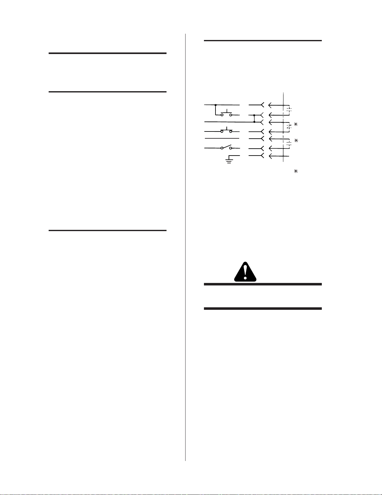
22. T o interface the Contr ol Panel with a Computer
Control connect the Computer Interface Cable
(BLUE/ORANGE) to the middle receptacle
(color-coded the same) on the rear of the Control Panel. Figure 2-H shows the direct relationship of the Computer Interface Cable with
the Control Panel. The dotted lines indicate
input and output signals required from a computer to operate the TA500 System. The Control Panel Station Select signal is optional and
must be jumpered if not used.
W ARNING
Do Not Stand In Front of the V alve Outlet When
Executing Step 23.
23. Examine the cylinder valve and ensure that it
is clean and free of oil, grease and other foreign
matter. Momentarily open the cylinder valve
to blow out any dust which may be present.
24. Connect the appropriate regulator on the cylinder valve. The gas supplies must be equipped
with adjustable pressure regulators capable of
being set between 0 and 60 psi (0-4.1 bar) and
of delivering 150 Standard Cubic Feet per Hour
(SCFH) of N2 and 400 SCFH of CO2 or compressed air.
Pressure regulators for use with TDC units and
specifically calibrated for use with nitrogen
(Cat. No. 9-2722) and carbon dioxide (Cat. No.
9-2759) are supplied when a T A-500 System is ordered. They are also available from Thermal Dynamics as accessories, as are regulators for argon/hydrogen (Cat. No. 9-3053) and compressed air (Cat.
No. 9-3022).
Installation 2-4 Manual No 0-0470
Page 25

25 . Connect the plasma gas supply hose (BLACK) to
the plasma gas cylinder and the fitting on the rear
panel of the Control Console marked PLASMA GAS.
26 . Connect the secondary gas (if used) supply hose
(YELLOW) to the secondary gas cylinder and
the fitting on the rear panel of the Control Console marked SECONDARY GAS.
NOTE
30. Remove the cover from the Supply Console.
31. Pass the torch leads and arc starter connector through
the larger plastic bushing on the rear panel of the
Supply Console.
32. The torch leads are color-coded. Attach them to the
appropriate (color-coded) fittings on the bulkhead
board. Connect the arc starter plug to the receptacle
marked ARC STARTER.
A typical 50-lb CO2 cylinder is capable of delivering 35 SCFH on a continuous basis. Therefore, it may be necessary to manifold several cylinders to obtain the required torch flow rate,
depending on the application and duty cycle.
27. If water shield will be used as the secondary,
connect secondary water supply hose (YELLOW) to the water source and the rear panel of
the Supply Console marked SECONDARY WATER SHIELD.
NOTE:
The water source must be capable of delivering a
minimum water pressure of 20 psi. This water
does not need to be deionized, but in water systems with an extremely high mineral content a
water softener is recommended.
Arc Starter
A box housing some of the Arc Starter components is
shipped separately. It must be mounted close to the
torch (usually on the torch lifter frame) and connected
to the torch leads. The 16-pin connector protruding
from the torch leads covering is connected to the end
of the box marked WHITE/YELLOW. The wire lead
color-coded RED is connected to the end of the box
marked RED. The wire lead color-coded GREEN is connected to the end of the one marked GREEN.
M200 T orch
28. Check the torch to see that it is properly assembled (refer to Section 4-1).
33 . Replace the cover on the Supply Console and se-
cure.
Hi-flow Water Shield (Optional)
NOTE:
Refer to the instruction manual packed with the
Hi-Flow Water Shield for installation instructions.
34. Connect the Hi-Flow starter control cable to the
receptacle marked HI-FLOW WATER SHIELD
on the front panel of the Power Supply.
CAUTION
The 115 VAC power from the TA-500 Power
Supply is to operate the contactor of the HiFlow Water Shield pump only. It will not operate the motor.
1000 Amp System (Two TA-500 Power
Supplies)
T o connect two (2) T A-500 Power Supplies together for a
1000 amp system the first (master) unit is connected as described in step 1 through 36. The second (slave) unit is
connected per steps 1 through 11 with the additional interconnecting step.
35. Connect the end of the Parallel Control cable colorcoded WHITE to the receptacle marked P ARALLEL
RELA Y on the front panel of the first (master) Power
Supply . Connect the end color-coded YELLOW/
ORANGE to the receptacle REMOTE P ANEL CONTROL on the second (slave) unit.
NOTE:
WARNING
Underwater cutting requires special insulated
torch parts. See Figure 5-10.
29. The torch is normally shipped attached to the
gas and water leads. If this is not the case, refer to Section 4-1.
Manual No 0-0470 2-5 Installation
There should be 2 negative (GREEN) cables
from each of the two Power Supplies to the Supply Console and 2 positive (RED) work cables
from each of the two Power Supplies to the workpiece.
36 . Inspect all connections to ensure that they are se-
curely made and tightened. Check that all covers
and panels are replaced and secured.
Page 26

CAUTION
Do not attempt to operate this system unless all
parts of all enclosures are in place. This is important for proper cooling as well as for safety.
WARNING
Care should be taken when working around the
unit when the power is turned on. No changes
of electrical connections or torch parts should be
attempted unless the primary power is first
turned off.
37. Turn on the primary power and verify the direction of rotation of the fan motor. It should
blow air out the back of the unit. If air is not
blown out the back of the unit, the rotation is
incorrect and any two motor leads (lines 44, 45,
or 46) on the transformer terminal board should
be switched.
38. When the ON-OFF switch on the Control Console is moved to ON the HE 200 should come
on. Run the Coolant Recirculator for several
minutes to remove air trapped in the lines. After running for a few minutes, turn the
Recirculator OFF and remove the reservoir cap.
Bring the coolant up to the level of the
crosswires and install the Reservoir Cap/Cartridge Assembly supplied with the unit. Replace the cover and secure.
39. The System is now ready for operation.
Installation 2-6 Manual No 0-0470
Page 27

SECTION 3: OPERATION
3
6
7
8
3.1 Operating Controls
2
4
5
AC POWER
READY
ON
OFF
1
0 200 400 600 800 1000
D.C. AMPERES
6
5
4
3
2
1
10
CURRENT CONTROL
7
8
9
START
STOP
9
NORMAL
SOFT
START
PIERCE
RUN
PURGE
SET
Red STOP button is pressed to stop the cutting cycle
and turn off the power to the torch.
7. RUN/PURGE/SET Switch (SW6)
Move to the PURGE (center) position to purge the
plasma gas in the torch. SET (down) position is
used to set the plasma and secondary flow rates.
The Power Supply cannot be actuated in either the
PURGE or SET position but will operate normally
in the RUN (up) position.
8. NORMAL/SOFT START/PIERCE Switch (SW2)
This three-way switch is used to set the mode of
operation of the Power Supply. Most cutting will
be done in the NORMAL (up) position. For rapid
piercing the PIERCE (down) position gives a current surge when the tor ch is first started. The SOFT
ST ART (center) position is a low power start which
is useful in prolonging the orifice life of small tips.
9. START Switch (SW2)
Green START button is pushed to initiate the cutting cycle.
Figure 3-A Operator Control Panel
1. Ammeter (AM)
Indicates amperage supplied to torch.
2. AC POWER Indicator (LT3)
Red light indicates that Primary AC power is being supplied to the system.
NOTE: Fan is on when light is on.
3. “Ready” Indicator (LT4)
Amber light indicates that the ON/OFF switch is
in the ON position and that all system requirements
are met.
4. ON/OFF Switch (SW1)
Move up to ON position to turn on HE 200 and
activate control circuits. Move down to OFF position to deactivate control circuits.
5. CURRENT CONTROL Knob
Adjust knob while cutting until desired current is
read on Ammeter.
6. STOP Switch (SW3)
Manual No 0-0470 3-1 Operation
Page 28

14. HI-FLOW W A TER SHIELD ON/OFF Switch (SW8)
11
10
1FU
AC POWER
DC POWER
100
200 300
AMPERES
D.C.
PILOT
16
12
2FU
AUTO
MAN
200 300
400
100
500
3FU
SURFACE
UNDERWATER
DO NOT SWITCH
UNDER LOAD
400
VOLTS
D.C.
15
13
4FU
ON
OFF
500
Figure 3-B TA-500 Power Supply Front Panel
10. AC POWER Indicator
14
HI-FLOW
WATER SHIELD
The ON position activates the circuitry for the hi-Flow
W ater shield (optional) control. The OFF position deactivates the circuit.
15. V oltmeter
Indicates the voltage between the torch electrode
and the workpiece (voltage on main bridge rectifier). Useful in troubleshooting.
16. Ammeter
Indicates amount of cutting current being supplied
from the Power Supply to the torch.
17
PLASMA
20
18
SECONDARY
GAS
WATER
SHIELD
19
COOLANT
21
Red light indicates that Primary AC power is being supplied to the Power Supply.
NOTE: Fan should be running when this light is
on.
11. DC POWER Indicator
Red light indicates that main contactor (W) has
closed to supply current to the main bridge rectifier and that cutting current is available.
12. PILOT AUTO/MAN Switch (SW9)
With the switch in the MAN position the pilot arc
will start two seconds after the green START button is pressed and will stay on for 2 seconds only.
The main cutting arc must transfer in this time. If
the pilot arc goes out press the red STOP button,
and the green START button to recycle the torch.
The torch must be recycled after each cut to start
the pilot arc again. In the AUT O position the pilot
arc will remain on until the cutting ar c is transferred
and will restart when the cutting arc goes out.
13. SURFACE/UNDERWATER Switch (SW8)
Figure 3-C Supply Console Front Panel
17. PLASMA Gauge
Indicates pressure at which plasma gas is being supplied to the torch.
18. SECONDARY Gauge
Indicates pressure at which secondary gas is being
supplied to the torch.
19. SECONDARY Flowmeter
Indicates flow rate at which secondary water is
being supplied to torch.
20. GAS/WATER SHIELD Switch (SW7)
Used to select either gas or water as a secondary.
21. COOLANT Gauge
Indicates pressure at which coolant is supplied to
the torch.
Selects the proper resistance value of the pilot resistor for the type of cutting operation.
NOTE: Do not switch under load.
Operation 3-2 Manual No 0-0470
Page 29

3.2 Pre-Operation Set-up
This procedure should be followed at the beginning of each
shift:
WARNING
Check to be sure main disconnect switch is open.
1. Check the coolant level in the Coolant
Recirculator and fill to proper level if necessary.
10. Check the position of the HI-FLOW WA TER SHIELD
ON/OFF switch and the PILOT AUTO/MAN switch
on the Power Supply for desired operating mode.
Surface or Underwater Cutting
11. The two cutting modes, Surface and Underwater , require a different pilot resistance. This is easily selected using the SURF ACE/UNDERW ATER switch
on the T A500. The M200 torch also requires dif ferent parts for underwater operation. Refer to Section
4.1 for details.
Bevel Cutting
2. Check the torch to be sure it has the proper components and is assembled and adjusted correctly.
3. Close the main disconnects supplying 3-phase
power to the Power Supply, Coolant
Recirculator and Hi-Flow W ater Shield (if used).
4. Turn the ON/OFF switch on the Control Panel
to ON. The Coolant Recirculator will come on.
The amber READY light will come on. (If the
gas supply is on, the gases will flow for 2 seconds).
5. Select the plasma gas pressure for the type of
cutting to be done from Table 3-B. Move the
RUN/SET/PURGE switch to the SET position.
Open the plasma gas supply valve at the source.
Adjust the pressure regulator on the gas supply until the plasma pressure selected from the
Table is obtained.
6. Move the switch to PURGE for approximately
3 minutes (this allows the plasma gas to run).
This will remove any condensation or moisture
that may have accumulated in the torch while
it was shut down. If there is any sign of moisture after purging, determine the cause and
correct it before operating the system.
NOTE:
12 . Bevel cutting requires a greater standoff distance
due to the angle of the torch. The pilot resistance
therefore must be changed to ensure that the main
arc will transfer and that proper standoff will be found
when using an SC504 Standoff Control. The proper
resistance for surface bevel cutting is obtained by
moving the SURF ACE/UNDERW ATER switch to the
UNDERW A TER position.
When bevel cutting, underwater resistance value of
the pilot resistor (R2) must be adjusted. Consult the
Thermal Dynamics Customer Service Department for
assistance in obtaining the correct resistance value.
The system is now ready for operation.
3.3 Operation
W ARNING
Be sure the operator is equipped with proper
eye and ear protection and that all precautions
in the front of this manual have been followed.
1. The M200 torch must be at right angles to the plate
to obtain a clean, vertical cut. Use a square, as shown
in Figure 3-F , to align the torch.
Only the plasma gas needs to be purged.
7. Return the RUN/SET/PURGE switch to the
SET position and open the secondary supply
valve at the source. Adjust the pressure regulator at the gas supply until pressure reads 60
psi (4.1 bar) or turn on the secondary water if
water shield cutting and set at about 12 gph.
8. Return the RUN/SET/PURGE switch to the
RUN position.
9. Set the CURRENT ADJUST knob on the Control Panel for desired amperage level.
Manual No 0-0470 3-3 Operation
Page 30

3. Adjust the cutting speed for good cutting perfor-
x.
mance, as indicated by a trailing arc of approximately
5 degrees (Fig. 3-G).
5o Appro
Figure 3-F Using a Square to set up the M200 Torch
2 . To start a cut at the edge of the plate, line up the
torch away from the plate and press the ST AR T
button on the Control Panel. The pilot arc characteristics will depend on which PILOT mode
is selected (see 3.1.12) and the position of the
SURFACE/UNDERWATER Switch (3.1.13).
The cutting arc will be established at the plate
edge as the torch approaches the plate.
Figure 3-G Proper Cutting Speed Produces a Trailing
Arc of Approximately 5 Degrees
4. In some cutting operations, it may be desirable to
start the cut within the plate area rather than at the
plate edge. Piercing is not recommended in over 2inch (50 mm) thick material when using W ater Shield.
When a lot of piercing is required, a special tip (Cat.
No. 8-6047) and end cap (Cat. No. 8-6057) should be
used. T o pierce, set the NORMAL/SOFT ST ART/
PIERCE switch to the PIERCE position (see 3.1.8).
NOTE:
The suggestions listed below should be followed
in all cutting operations:
1. At shut down wait five minutes before moving
the ON/OFF switch to OFF and opening the
main disconnect switch. This allows the Power
Supply and torch to cool down.
2. For maximum parts life, do not operate the pilot arc any longer than necessary.
3. Remember that cutting current can be adjusted
at any time (see Instruction Manual for Standoff Control). Learn to change the current output to provide a comfortable working speed
for the particular material being cut.
4. Use care in handling torch leads and protect
them from damage.
Operation 3-4 Manual No 0-0470
Page 31

5. In continuous cutting applications, it is often neces-
el
(
sary to manifold 4 to 6 CO
maintain pressure.
6. Because of the swirl of the plasma gas in the torch,
the right-hand side of the cut (in relation to the
torch travel, as shown in Fig. 3-H) is normally of
better quality . A reverse swirl electrode is available
for applications requiring the better quality be on
the left side of the cut (in relation to the torch travel).
cylinders together to
2
Torch Trav
3.4 Cutting and Speed Selection
The desired cutting current and the speed at which the torch
is moved along the line of the cut depends on the thickness
and composition of the workpiece. Use T able 3-B as a starting guide to establish the proper cutting speed for the material being cut.
COMMON CUTTING FAULTS
Listed below are common cutting problems followed by probable causes of each. If problems are caused by the T A-500
system, refer to the trouble shooting section (Section 4).
1. Insufficient Penetration
a. Cutting speed too high
b. Current too low
2. Main Arc Extinguishes
a. Cutting speed too slow
b. Standoff too high
3. Dross Formation
a. Improper gas pressure or mixture
Scrap
Beveled)
Side
Better
(Square)
Side
Figure 3-H Direction of Gas Flow Using Standard Gas
Distributor
WARNINGS
FREQUENTLY REVIEW THE SAFETY PRECAUTIONS GIVEN AT THE FRONT OF THIS
MANUAL.
b. Improper cutting speed
c. Faulty electrode or tip
d. Current too high
e. Stand-off too low
4. Burned-Out Tips
a. High cutting current
b. Damaged or loose cutting tip
c. Contact with work
d. Heavy spatter
e. Low plasma gas pressure
f . Improper selection of SOFT/NORM/PIERCE
It is not enough to simply move the ON/OFF
switch on the Control Panel to its OFF position
when cutting operations have been completed.
Always open all power disconnect switches 5
minutes after the last cut is made.
Manual No 0-0470 3-5 Operation
Page 32

Table 3-B Recommended Cutting Speeds
INCHES/MINUTE (METERS/MINUTE)
1/2" (12. 7 m m )
3/4" (19 mm )
INCHES/MINUTE (METERS/MINUTE)
1" (25. 4 mm )
1-1/2" (38 m m )
INCHES/MINUTE (METERS/MINUTE)
2" (50. 8 mm )
INCHES/ M INUTE (METE RS/ M INUTE )
1/4" (6 mm)
1/2" (12. 7 m m )
The following charts are intended as a guide in determining approximate conditions for making good quality
cuts in various thicknesses of material. Slower speeds may generally be obtained by reducing the current.
250 Amperes
The speeds below are typical for cutting at 250 amperes using the 8-6042 tip and the 8-6006 end piece.
GENERAL PURPOSE WA TER SHIELD
Plasma gas: N2 at 60 psi (4.1 bar) (85 scfh) Plasma Gas: N2 at 60 psi (4.1 bar) (85 scfh)
Secondary gas: CO2 at 60 psi (4.1 bar) (85 scfh) Secondary: Water - 12 gph
THICKNESS:
BEST MAX BEST MAX
St ai nless S teel 140 (3.56) 250 (6.35) 85 (2.16) 125 (3.18)
Alum i num 135 (3.43) 250 (6.35) 100 (2.54) 135 (3. 43)
Carbon Steel 100 (2.54) 200 (5.08) 60 (1.52) 80 (2.03)
500 Amperes
The speeds below are typical for cutting at 500 amperes using the 8-6044 tip and the 8-6006 end piece.
GENERAL PURPOSE WA TER SHIELD
Plasma gas: N2 at 60 psi (4.1 bar) (95 scfh) Plasma Gas: N2 at 60 psi (4.1 bar) (95 scfh)
Secondary gas: CO2 at 60 psi (4.1 bar) (350 scfh) Secondary: Water - 12 gph
THICKNESS:
BEST MAX BEST MAX
St ainl ess Steel 150 (3.81) See Note B 90 (2.29) 125 (3.18)
Alum i num 180 (4.57) See Note B 110 (2.79) 140 (3.56)
Carbon Steel 75 (1.9) 125 (3.18) 55 (1.4) 75 (1. 9)
THICKNESS:
BEST MAX BEST MAX
St ainl ess Steel 60 (1.52) 80 (2.03) 40 (1.02) 50 (1.27)
Alum i num 80 (2.03) 100 (2. 54) 50 (1.27) 60 (1.52)
Carbon Steel 35 (0.89) 50 (1.27) 20 (0.51) 30 (0.76)
THICKNESS:
BEST MAX
St ainl ess Steel 25 (0.64) 30 (0.76)
Al uminum 35 (0. 89 ) 45 (1.14)
Carbon Steel 15 (0.38) 25 (0.64)
Operation 3-6 Manual No 0-0470
Page 33

750 Amperes
1" (25.4 m m )
1-1/2" (38 m m )
INCHES/ M INUTE (METE RS/ M INUTE )
1/2" (12. 7 mm )
3/4" (19 mm )
INCHES/ M INUTE (METE RS/ M INUTE )
3" (76 mm )
4" (102 mm )
INCHES/ M INUTE (METE RS/ M INUTE)
2" (51 mm )
2-1/2" (64 m m )
INCHES/ M INUTE (METE RS/ M INUTE)
The speeds below are typical for cutting at 750 amperes using the 8-6045 tip and the 8-6006 end piece.
GENERAL PURPOSE WA TER SHIELD
Plasma gas: N2 at 60 psi (4.1 bar) (100 scfh) Plasma Gas: N2 at 60 psi (4.1 bar) (100 scfh)
Secondary gas: CO2 at 60 psi (4.1 bar) (350 scfh) Secondary: Water - 12 gph
THICKNESS:
BEST MAX BEST MAX
St ai nless Steel 180 (4.57) S ee Note B 120 (3.05) 150 (3.81)
Alum i num 200 (5.08) See Note B 160 (4.06) 180 (4.57)
Carbon Steel 140 (3.56) See Note B 75 (1.9) 95 (2.41)
THICKNESS:
BEST MAX BEST MAX
St ai nless Steel 80 (2.03) 100 (2.54) 50 (1.27) 60 (1.52)
Alum i num 100 (2.54) 130 (3.3) 80 (2.03) 100 (2.54)
Carbon S teel 50 (1. 2 7) 65 (1.65) 30 (0 . 7 6) 40 (1.02)
1000 Amperes
The speeds below are typical for cutting at 1000 amperes using the 8-6046 tip and the 8-6006 end piece.
For material under 3” (76 mm) thick:
GENERAL PURPOSE
Plasma gas: N2 at 60 psi (4.1 bar) (110 scfh)
Secondary gas: CO2 at 60 psi (4.1 bar) (350 scfh)
For material over 3” (76 mm) thick:
GENERAL PURPOSE
Plasma Gas: N2 at 60 psi (4.1 bar) (110 scfh)
Secondary: Ar/H2 at 25 psi (1.7 bar) (250 scfh)
THICKNESS:
BEST MAX BEST MAX
St ai nless Steel 50 (1.27) 65 (1.65) 35 (0.89) 50 (1.27)
Alum i num 60 (1. 52) 75 (1. 9) 55 (1.4) 70 (1.78)
THICKNESS:
BEST MAX BEST MAX
St ai nless Steel 20 (0.51) 30 (0.76) 10 (0.25)
Alum i num 40 (1. 02) 60 (1.52) 20 (0.51)
Note A: This information repr esents our best judgement but Thermal Dynamics Corporation assumes no liability for its use.
Note B: Exceeds maximum speed of most motorized torch carriers.
Manual No 0-0470 3-7 Operation
Page 34

Operation 3-8 Manual No 0-0470
Page 35

3
9
5
4
1
2
6
7
8
10
13
19
15
14
11
12
16
17
18
20
18
21
3
12
14
SECTION 4: SERVICE
The Service Section is divided into nine parts:
4.1 Torch Maintenance
4.2 TAC 500 Power Supply Maintenance
4.3 HE 200 Coolant Recirculator Maintenance
4.4 Gas Pressur e Regulators
4.5 Troubleshooting Guide
4.6 Returns
4.7 Primary Voltage Selection
4.8 Trouble-Shooting
4.9 Test Procedur es
WARNING
Disconnect the primary power before disassembling the torch.
4.1 Torch Maintenance
Disassembly
1. Unscrew the collar (19) and pull the end cap
(17) off. The end piece (16) and O-ring (15) will
remain in the end cap when it is removed.
2. Remove the coolant baffle (20) from the front of
the inner tip retainer (9).
3. Pull the outer insulator (13) off.
4. Unscrew the inner tip retainer (9). The cutting
tip will remain in the inner tip retainer . If additional leverage is needed to remove this part
insert a 5/32 inch diameter rod in one of the
large holes.
5. Remove the tip (6) from the inner tip retainer
by pressing back on the front of the tip. Considerable pressure may be needed to push the
tip past the O-ring seals.
6. Remove the electrode (5) from the torch by unscrewing it from the electr ode seat (4). The electrode seat does not need to be removed from
the torch unless it has been damaged.
7. Remove the water tube (2) by lifting it out of
the torch.
Figure 4-A M200 Torch
Manual No 0-0470 4-1 Service
Page 36

3
9
5
4
1
2
6
7
8
10
13
19
15
14
11
12
16
17
18
20
18
21
3
12
14
For routine disassembly of the torch, no other parts need
to be removed. The electrode seat (4) does not requir e
replacement unless it has been damaged by a severe
electrode failure. This part unscrews from the center
post of the torch and should be gripped with a piece of
emery cloth. If necessary , pliers may be used very gently to remove this part.
Torch Assembly
CAUTION
There are several O-ring seals in this torch to
prevent leakage of the coolant. It is important to
observe the following precautions for all O-rings:
A. Make sure that the O-ring groove and the sur-
face that the O-ring will seal against are clean
and free of nicks and scratches.
B. Make sure that the O-ring is not cut or cracked.
C. Lubricate all O-rings with a light coating of Cat.
No. 8-4025 O-ring lubricant. This should be
used sparingly , just enough to make the O-ring
slippery but not enough to accumulate in the
torch.
If a new electrode seat (4) is installed in the torch, the
O-ring (3) in the center post of the torch should be replaced before installing the new one. The new electrode seat may be gripped with emery cloth and
screwed into the center post of the torch. It is not necessary to use pliers.
When assembling the torch, proper orientation of the
coolant baffle (20) relative to the M200 basic head assembly (1) is important. The basic head assembly has
two projections on the sides of the plastic body that are
called ‘marks’ in step 8 below.
Assemble the torch as follows:
1. Install a new O-ring in the electrode seat. This
O-ring is included with each new electrode. The
O-ring is installed in the groove located about
3/8” (9.5 mm) back from the front of the elec-
trode seat.
2. Install the water tube (2) in the center of the
3. Install the electrode (5). Make sure it screws in
torch, small end first.
all the way.
4. Install new O-rings in the inner tip retainer (9).
These O-rings (7 and 8) are supplied with each
new cutting tip. The should be lubricated lightly
with Cat. No. 8-4025 O-ring lubricant and
placed in the proper groove in the tip retainer.
Figure 4-B M200 Torch
Service 4-2 Manual No 0-0470
Page 37

5. Install the new tip (6) in the inner tip retainer.
This is installed by pressing it in from the back.
If the O-rings are properly lubricated, thumb
pressure is adequate (with a slight twisting
motion of the thumb).
6. Install the inner tip retainer with the tip in place
on the front end of the torch. The tip retainer
must be screwed completely into place. It is
essential that the ceramic O-ring on the tip be
firmly in contact with the electrode.
7. Install the outer insulator (13) on the torch.
Before pushing this into place, make sure that
the O-rings on the inside diameter are in good
condition and properly lubricated. The insulator must be pushed onto the torch as far as it
will go.
8. Install the coolant baffle (20) on the front of the
inner tip retainer . The triangular projections go
into the holes in the inner tip retainer that are
aligned with the marks on the plastic torch body .
If the holes do not align exactly, use the closest
ones. DO NOT loosen the inner tip retainer to
improve the alignment.
9. Install the end piece (16) in the front of the end
cap, small end forward.
10. Install O-ring (15) in the end cap against the
back of the ceramic end piece. A light coating
of O-ring lubricant will help hold this O-ring in
place until the end cap is installed.
11. Press the end cap (17), complete with end piece
(16) and O-ring (15) in place, onto the outer insulator (13). Install the collar (19) over the end
cap (17) and screw it onto the torch body.
This completes the torch assembly. There is a chance
that water may get in the plasma gas passages in the
torch during assembly. All water must be removed
before operation.
To remove all traces of water:
1. Turn the Console RUN/SET switch to SET.
2. Turn on the coolant.
3. Turn on the plasma gas (nitrogen). Do not turn
on the shield water (water shield cutting). The
shield gas may be on or off (dual flow cutting).
4. With plasma gas flowing, look for traces of
moisture in the gas stream.
W ARNING
Do not operate the torch unless the plasma gas
stream is completely free of moisture.
Be sure to turn on the secondary gas or shield water
before starting to cut.
4.2 TAC 500 Power Supply Maintenance
The only routine maintenance the T AC 500 Power Supply requires is an occasional removal of the cover and
side panel and a thorough blowing out of dust with an
air hose.
4.3 HE 200 Coolant Recirculator Maintenance
Parts in the HE 200 Coolant Recirculator require routine maintenance. The coolant level should be checked
daily and Thermal Arc coolant added to keep the level
at the crosswires in the cylindrical section. If Thermal
Arc coolant is not available, distilled or deionized water may be used if the temperature does not go below
freezing. The resistivity of the water must measure
above .1 megohm cm.
CAUTION
Do not use tap water . It could cause severe damage to the torch.
The reservoir contains a cap/cartridge assembly which
includes a small cartridge of deionizing resin to maintain the resistivity of the coolant. The cartridge must
be replaced when it changes from gray to straw color.
A coolant filter with a r eusable scr een is located above
the pump. The screen should be removed and cleaned
once every six months or at any time the coolant pressure drops. To remove the filter screen, remove the
top of the HE 200 unit and unscrew the hex nut on the
bottom of the filter housing.
The coolant recirculator has a pressur e relief valve that
is factory set at 150 psi (10.3 bar) and should not require
adjustment. Normal operating pressure is approximately 110 psi (7.6 bar). If the pr essure relief valve must
be adjusted see the HE-200 manual.
Manual No 0-0470 4-3 Service
Page 38

The pump is pre-greased at the factory and should only re-
5
quire lubrication every two years. T o lubricate, remove screws
from the two grease fittings on top of the pump and apply
grease supplied with the HE 200 unit.
CAUTION
Do not over-lubricate the pump; it will cause
pump failure.
The fan belt may become loose due to usage. The belt
tension should be such that moderate finger pressure
(about mid-distance from pulley to pulley) gives about
1/4 inch (6 mm) deflection. The belt tension may be
adjusted by changing the width of the gap on the large
adjustable pulley . Using a 5/32 hex key wr ench loosen
the two set screws 180 degrees apart on side of pulley.
Remove key and rotate by half turns until desired gap
is obtained. Replace the square key and tighten set
screws again.
2
1
A-01894
3
4
6
4.4 Gas Pressure Regulators
The Thermal Arc gas pressure regulators provide a
means of conveniently selecting and maintaining the
required working pressures of the gases. The regulator will hold this pressure constant. Inlet pressure is
reduced in one step to the working pressure by means
of a pressure balanced poppet valve controlled by a
spring loaded piston in a low pressure chamber . A lar ge
adjusting spring knob (6, Figure 4-C) provides for adjusting spring pressure against its piston. A sintered
stainless steel filter , in the inlet connector (1), pr events
dirt from entering the regulator mechanism.
No regular maintenance of the gas pressure r egulators
is required, except an occasional lubrication of the adjusting screw thread and on its end, where it contacts
the adjusting spring. Lubricant is available from Thermal Dynamics for this purpose (Catalog No. 9-2781).
Replacement parts in the regulator include the pressure gauges, the O-ring seals on the piston and above
the poppet valve, and the poppet valve. (See Assembly Parts List Fig. 5-12 for replacement parts).
1. Inlet connection
2. Inlet pressure gage
3. Safety valve
4. Working pressure gage
5. Hose connection
6. Adjusting knob
Figure 4-C Components of Gas Pressure
Regulator
CAUTION
Do not attempt to remove the sintered metal filter in the inlet connection. This is not a serviceable item.
Service 4-4 Manual No 0-0470
Page 39

ACTION
1. Torch brought close (approximately
1/2 inch) to workpiece.
RESULTS
1. Arc transfers to workpiece to establish
CUTTING ARC.
2. Current sensing circuit turns off pilot arc.
3. Depending on the position of the PILOT
ACTION
1. STOP button pressed.
RESULTS
1. Red DC POWER light off.
2. Pilot arc stops.
After two seconds:
ACTION
1. Torch moved away from workpiece
or workpiece burns away
PILOT
AUTO/MAN switch the arc starter will be
turned off by either relay CSR (AUTO) or
time delay relay (MAN).
4. 'Pre-start' saturating current turned on by relay CSR.
5. Standoff Control circuitry is energized by relay CSR.
6. Current regulating circuit is energized by relay CSR.
7. Hi-Flow Water Shield turned on by relay CSR.
ACTION
1. Protect eyes and press START
button.
READY
SYSTEM
3. Plasma gas and secondary
or water flow stops.
under torch.
RESULTS
1. CUTTING ARC stops.
2. Hi-Flow Water Shield shuts off
RESULTS
1. Plasma gas and secondary gas
or water pressure switches close.
2. Main contactor closes. Red DC
automatically.
PILOT AUTO/MAN switch in
AUTO position:
3. Pilot arc comes on until CUTTING
ARC is transferred or STOP
button is pushed.
PILOT AUTO/MAN switch in
MAN position:
3. No Pilot arc.
4. DC POWER light remains on,
POWER light on.
3. Reactor saturating current is
turned on. The amount of satur-
ating current depends on the
position of the NORMAL/SOFT
START/PIERCE switch (this
is for 'pre-start' only).
After two seconds:
4. Pilot arc relay closes.
5. Arc starter circuit energized.
gases continue to flow.
5. No cutting arc.
6. Pilot arc turns on.
SYSTEM READY
ACTION
1. RUN/SET/PURGE switch
(SW6) to RUN.
2. Select cutting amps with
CURRENT CONTROL knob.
RESULTS
1. Gas flow stops.
2. Power circuits ready.
or water solenoids open. Plasma
gas and secondary gas or water
flow so pressure can be set.
2. Power circuits disabled.
ACTION
1. Close all three external disconnect
switches (TA500, HE200,
Hi-Flow Water Shield)
RESULT
1. Red AC POWER light (LT3) on and
fan starts in TA500.
ACTION
ACTION
1. RUN/SET/PURGE switch
(SW6) to PURGE.
1. ON/OFF switch (SW1) to ON.
RESULTS
1. HE200 starts to pump coolant to
torch via Supply Console
2. Coolant pressure reaches 100 psi.
3. Amber READY light (LT4) turns on.
4. Plasma gas and secondary gas
or water shield solenoids open
and gases (or water) flow.
RESULTS
1. Plasma gas solenoid only
opens allowing the plasma
line to be purged.
After two seconds:
5. Gas (or water) flow stops.
ACTION
1. RUN/SET/PURGE switch
(SW6) to SET.
RESULTS
1. Plasma gas and secondary gas
Manual No 0-0470 4-5 Service
Page 40

4.5 Troubleshooting Guide
If the T A-500 System malfunctions the troubleshooting guide
will be helpful in correcting the problem. Since the malfunction may be due to a faulty connection rather than a faulty
component, be sure to check all connections to a component
that appears to be malfunctioning.
The troubleshooting guide is arranged in the normal operating sequence of the system for easy reference. Each problem
has listed next to it the possible causes and the remedy .
In some cases the remedy is too complex to fit the table, in
which case there is a reference to one of the “Test Procedures”.
4.6 Returns
If a product must be returned for service, contact your distributor. Material r eturned without proper authorization will
not be accepted.
C. No READY Light (Control Panel).
1. Coolant pressure switch PS2 in Supply Console open
(pressure below 75 psi/5.2 bar).
a. Check coolant level in HE200. Clean pump
filter screen. Adjust pump. Replace pump.
2. Pressure switch PS2 in Supply Console not satisfied.
a. Adjust (75 psi/5.2 bar) or replace PS2. (See
A, Section 4.8).
D. Gases do not flow when “ready” Light comes
on.
1. Gas supply not on.
a. Open valve.
2. Faulty post flow time delay (TD1).
a. Check TD1 (See B, Section 4.8).
4.7 Primary Voltage Selection
The T A500 transformers are manufactured for two voltage ranges. These ranges are specified on the Serial
Number Tag attached to the front of the unit. If the
voltage ranges must be changed, the proper connections are shown on the transformer terminal board.
4.8 Trouble-Shooting
Some of the circuitry of the Standoff Control can af fect
the characteristics of the Power Supply and T orch, therefore it should be disconnected at the connection marked
POWER SUPPLY on the bottom left hand side of the
SC electronic unit inside the Power Supply . The jumper
connector, mounted to the wiring harness, should be
connected to the wiring harness connector. This will
avoid any interference of the Standoff Control while
troubleshooting the Power Supply . (See SC 504 instr uction manual for trouble-shooting the Standoff Control).
A. No AC POWER Light on TAC 500.
1. Blown fuse or open circuit breaker at primary.
1. Replace fuse or reset breaker.
B. No AC POWER Light on Control Panel.
1. Supply Console cover interlock switch (SW5) not actuated or bad.
E. Gases flow more than 2 seconds.
1. RUN/SET/PURGE switch in set.
a. Move to RUN.
2. Faulty post flow time delay (TD1).
a. Check TD1 (See B, Section 4.8).
F. Cannot set desired gas pressures.
1. Empty gas cylinders.
a. Replace.
2. Faulty gas regulator.
a. Repair or replace.
3. Faulty Solenoid Valve.
a. Replace.
When the START button is pressed, the gases and red
DC POWER Light should come on. If this does not
happen, check as follows:
G. Gas does not flow when START button is
pressed.
1. Faulty control relay 4CR.
a. Check relay (See C, Section 4.8).
2. START switch SW9 not closing.
a. Check cover for proper installation. Replace
SW5 if bad.
2. Blown fuse (4Fu) in TAC 500.
a. Replace fuse.
Service 4-6 Manual No 0-0470
a. Check for continuity when pressed.
3. No 24 volt power.
a. Check transformer T2.
Page 41

H . No red DC POWER Light.
4. Loose connection
1. Pressure switch PS3 in Supply Console not satisfied.
a. Check gas pressure setting (Plasma 60 psi/
4.1 bar).
2. Pressure switch out of adjustment.
a. Reset (See A, Section 4.8).
3. Main transformer overheated.
a. Allow to cool down.
4. Faulty main contactor (W).
a. Check contactor (See D, Section 4.8).
The Pilot Arc should start 2 seconds after the red DC
POWER Light comes on. If it does not, check the torch
parts to make sure they are in good condition and properly assembled. Next, check the Arc Starter unit for
loose connections and components for obvious failures.
Check to see if:
1) There is any “click” inside the Power Supply at the
time the Pilot Arc should start (2 seconds after pushing
ST AR T button).
I. No “click” inside the Power Supply 2 seconds
after the START button is pushed.
1. Faulty time delay TD2.
a. Check TD2 (See B, Section 4.8).
2. Faulty pilot control relay (PCR)
a. Check PCR
J. No Pilot Arc (or intermittent).
1. Damaged (defective) Torch parts.
a. Replace.
2. Dirty (wet) Plasma gas.
a. Purge.
b. Check for leaks on hoses and fittings.
c. Replace gas cylinders.
K. No Pilot Arc at all.
1. Blown pilot fuse (1Fu or 2Fu)
a. Replace.
2. Pilot contactor (PCR) not closing
a. Check PCR
a. Repair.
5. Gas purge relay (TD2) not closing
a. Replace TD2.
6. CSR activating prematurely.
a. Check for shorted toroid (See E, Section 4.8)
or bad relay P.C. board.
7. Pilot Bridge diodes (D17, 18, 19, 20) failed.
a. Check diodes (see G, Section 4.8, and Q, Sec-
tion 4.8).
8. Arc Starter transformer (T3) failed.
a. Check (See F, Section 4.8) and replace.
9. Diodes in Arc Starter Box shorted or open.
a. Check (See G, Section 4.8).
10. Arc Starter failed.
a. Replace.
L. Weak Pilot Arc.
1. Faulty Arc Starter/Shunt PC Board
a. Check PC Board (See N, Section 4.8). Replace
if needed.
2. Dirty coolant in HE200
a. Check HE200 deionizer cartridge (Section
4.3)
The Cutting Arc should start as soon as the tor ch, with
Pilot Arc running, is brought to within about 1/2 inch
(12 mm) of the workpiece. If it does not, check:
M. No Cutting Arc.
1. Work Cable not connected.
a. Connect.
2. One leg of 3 phase primary power out.
a. Check all 3 input phases for voltage.
3. One leg of main contactor (W) not closing.
a. Check voltage at diodes.
4. Main contactor (W) fails to operate.
a. Check relay (1CR); replace if needed.
b. Check thermal protection switch (TP1, 2, 3);
replace if needed.
3. Broken conductor in lead
a. Replace lead.
Manual No 0-0470 4-7 Service
c. Replace contactor.
Page 42

d. Check jumper wire in J8 connector; replace if faulty .
a. Check SCRs (See O, Section 4.8).
5. Reactor and/or transformer overheated due to exceeding the amperage rating of the Power Supply or
air flow restricted.
a. Reduce amperage to recommended ratings. Clear
air passages.
Once the Cutting Arc is established, the cutting curr ent
reading on the Control Panel ammeter should be adjustable by turning the CURRENT CONTROL knob. If
it is not, there is a problem in the current regulating
circuit as follows:
N. Unit only puts out minimum current (125 A).
1. Fuse 3Fu blown.
a. Replace.
2. Fuse blows again.
a. Check diodes and SCRs in control bridge (See
J & Q, Section 4.8).
3. Potentiometer failed.
a. Check (See K, Section 4.8).
4. Reactor disconnected.
a. Check (See L, Section 4.8).
5. Current Control P.C. board failed.
a. Check (See I, Section 4.8).
6. Relay CSR not closing.
a. Bad CSR. Replace (See M, Section 4.8).
b. Loose wire on toroid (T4). Correct.
c. Bad toroid (T4). (See E, Section 4.8).
d. Check Arc Starter PC Board (See N., Section
4.8).
O. Unit only puts out maximum current (500+ A).
1. Arc Starter/Shunt P.C. board failed.
a. Check P.C. board (See N, Section 4.8). Re-
place if faulty.
Cut quality begins okay but deteriorates during the
cutting process.
Q. Deteriorating cut quality.
1 Fr ozen CO2 r egulator.
a. Add heater.
b. Replace with high flow regulator.
2. Cylinder not delivering.
a. Manifold several cylinders together.
If the Torch parts life is short, check:
R. Short torch parts life.
1. Pilot arc remains on during cut.
a. Check CSR (See M, Section 4.8).
2. No prepurge gas flow.
a. Check time delay relay.
3. No post purge gas flow.
a. Check time delay relay.
4. Misuse of torch.
a. Use torch with ratings for current and work
thickness.
5. Incorrect gas pressure.
a. Check and correct.
6. Inadequate coolant flow.
a. Clean filter in HE200.
b. Adjust or replace pump in HE200.
7. Restricted coolant hose or lead.
a. Remove restriction or replace hose.
S. Discolored Electrode.
1. Contaminated gas.
a. Check plasma gas system for leaks.
2. Current Control PC Board failed.
a. Check PC Board (See I, Section 4.8). Replace
if faulty.
P. Unit can only put out about 375 amps maximum.
1. Current Control P.C. board failed.
a. Check P.C. board (See I, Section 4.8).
2. One SCR failed.
Service 4-8 Manual No 0-0470
2. No pre or post purge.
a. Check TD1 and TD2 (See B, Section 4.8).
3. Gas hoses switched.
a. Check.
Page 43

4.9 Test Procedures
The following tests are suggested for specific problems
listed in the preceding trouble shooting chart. The letter designation corresponds to those listed in the “Remedy” section of the chart.
WARNING
at the connections from the reactor . (220 volt 3 phase
power should always be present at lines 105, 106 and
107 when the primary power is turned on).
E . To check the toroid coil, measur e the resistance from
J400-5 to J400-6. It should be 22 ohms.
Several of these tests involve voltage measurements that must be made with power on. In order to make these measurements, the Supply
Console cover interlock switch must be propped
closed or bypassed. Use extreme care when making these tests and be sure to return the interlock switch to proper operation after work is completed.
T est r equiring voltage measurements ar e marked with
the warning symbol:
All other tests are to be made with the primary power
to the system turned off.
A. Pressure switches are located in the Supply Con-
sole on the PLASMA GAS line just inside of the
solenoid valve on the inlet fitting and on the
line running from the power manifold to the
NEG connection on the bulkhead board. The
switches are normally open. The pressure at
which the switches will close may be adjusted
by turning the knurled wheel just under the
plastic part of the switch. T urn clockwise to increase the pressure at which switch is actuated.
B. The two time delay relays, TD1 and TD2, are
interchangeable and can normally be checked
by swapping them. They are the “delay on operate” type with a 2 second delay.
F. The Arc Starter transformer (T3) has two dif-
ferent voltage outputs to check to verify its status. Using a voltmeter, place the probes between J400-19 and 20. This voltage should measure
280-330 V AC. Measure the voltage between J400-15
and 17. This should read 10-15V AC. Both voltages
must check out or the transformer is faulty .
G. A “quick check” can be made on the main diodes
without removing them from the circuit as follows:
Using an ohmmeter with the RX1 or RX10 scale,
measure the resistance of each diode in both directions. The readings should differ by at least a factor
of 10. If they do not differ (both high or both low)
the diode has failed and must be replaced.
H . The 3-phase AC input to the main bridge rectifier is
220 volts. This can be measured at the top of the
main bridge rectifier where the diode pigtails are joined
with the reactor leads (see Fig. 5-8) at any time that
the DC power light is on.
I. The best way to check the P .C. board is to replace it
with one known to be good. The current control PC
board in the P AK 10, 22, 44, and 350 can be used.
J. Locate the control bridge (see Fig. 5-8). Disconnect
the multi-conductor plug next to this component.
Using an ohmmeter with the RX10 scale, all diodes
should be checked for high resistance in one direction and low resistance in the other direction. The
SCRs should read a high resistance in both directions. If diode D16 is shorted, see ‘R’ below .
K. Remove the current regulating printed circuit card
C. The relay can be tested by removing it from the
relay socket and with the power on, measure
the voltage between pins A and B on the socket.
The voltage should read close to the voltage
specified for the relay. If it is, then the relay is
bad. If not, then the trouble lies in the circuitry.
D. T o check the main contactor remove the left side
panel of the machine. The contactor should
close when 115 volt AC is applied to lines 1 and
80 (when the ST ART button is pressed). At this
time, 220 volt 3 phase power should be present
Manual No 0-0470 4-9 Service
(see illustration below) from the power supply . W ith
the CURRENT CONTROL knob set at MIN measure
the resistance between the 3rd (pin 20) and 7th (pin
16) pins, counting from the top (see below). This
should read 0 ohms and increase smoothly to 10,000
ohms as the CONTROL knob is rotated to MAX.
Now measure the resistance between the 3rd (pin 19)
and 4th (pin 20) pins. This should read 10,000 ohms.
Page 44

22
1
9
16
20
L . With the contr ol bridge connected to the circuit, mea-
sure the resistance across the diode on the center
heat sink in both directions. It should read about 5
ohms both ways.
M. The coil of relay CSR should read about 3K ohms
measured from pin A to pin B on bottoms of relay .
N . The easiest way to check the PC Board is to replace
it with one known to be good.
1. An in-rush current surge is the most probable
cause of main diode failure. The in-rush surge is
prevented by capacitor C4 and resistor R6,10 in
series with each other across the output of the
bridge rectifier . The capacity and resistor , as well
as the wires connecting them to the circuit, should
be completely checked in any case of diode problems. The capacitor is a polarized capacitor , and
it is important to be sure that the side marked + is
connected to the positive side of the circuit.
2. High frequency protection for the diodes is provided by capacitors C5, C6 and C7 which are
installed between each side of the bridge rectifier . These capacitors and their connections
should be checked.
3. Overheating of the diode can occur if air flow
over the heat sink is inadequate or if the diode is
not properly fastened to the heat sink. Check to
see that the diodes are torqued to 25 foot pounds
(34 Nm) and that electrically conductive heat sink
compound (this is a white grease) is present
between the diode and heat sink. Also check for
normal operation of the fan and be sure that the
air passages into and out of the unit are not obstructed.
4. The diode that was faulty at the time of manufacture is difficult to diagnose. This usually fails
during the first few hours of operation. Before
deciding that this was the case, be sure to check
out the other three possibilities.
This concludes the trouble-shooting procedures.
O. With a soldering pencil, disconnect the ‘pigtail’
lead to the SCRs one at a time. When more than
one wire is connected to the pigtail, the two
wires should be connected to each other . Operate the unit with one and then the other SCR
disconnected and note the maximum amperage.
The output will remain unchanged when the
bad SCR is disconnected and will drop to minimum when the good SCR is disconnected.
P . Transformer T1 in the Standoff Control electronics
chassis can be checked by placing the probe of a
voltmeter in pins J23-18 and J23-20 of the PC board
connector . This voltage should read close to 25 V AC.
Q . A bad varistor (VR) is difficult to detect by itself.
However , it will cause the D16 diode on the control
bridge to short and burn out. If this happens or if the
varistor looks burnt, replace both.
Service 4-10 Manual No 0-0470
Page 45

SECTION 5: PARTS
LISTS
Assembly Parts List
The Assembly Parts List illustrates the parts of the
Thermal Arc 500 Cutting System and gives the catalog number for replacement parts.
An item number in parentheses indicates the item
is located behind the item pointed to. An asterisk
beside the item number indicates the part is a main
assembly, not a component. Parts listed without
item numbers are not illustrated, but may be ordered by the catalog number shown.
Oredering Information
When ordering replacements parts, order by catalog number and complete description of the part
or assembly, as given in the description column of
the Assembly Parts List. In addition, give the model
number of the machine, the machine serial number and its operating voltages, as given on the plate
attached to the unit in question. Address all inquires to your authorized distributor.
Manual No 0-0470 5-1 Parts Lists
Page 46

5.1 System Components
Item No. Qty. Description Ref. Cat. No.
1 1 TA500 Power Supply 3-5001
2 1 Supply Console 3-5002
3 1 Operator Control Panel (W ithout Enclosur e) 3-5007
1 Operator Control Panel (With Enclosur e) 3-5008
1 Control Panel Enclosure (Optional) 3-5009
4 1 M200 Torch with Mounting Tube 2-2766
5 1 Arc Starter 3-5003
6 1 HE200 Coolant Recirculator 7-3008
7 1 Hi-Flow Water Shield Assembly (Optional) 7-2962
1 15' M200 Torch Leads Package *4-5005-15
1 25' M200 Torch Leads Package *4-5006-25
1 35' M200 Torch Leads Package *4-5007-35
1 50' M200 Torch Leads Package *4-5008-50
1 15' Negative Water Cooled Lead *9-5031-15
1 25' Negative Water Cooled Lead *9-5037-25
1 35' Negative Water Cooled Lead *9-5043-35
1 50' Negative Water Cooled Lead *9-5049-50
1 15' Plasma Gas Hose *9-5032-15
1 25' Plasma Gas Hose *9-5038-25
1 35' Plasma Gas Hose *9-5044-35
1 50' Plasma Gas Hose *9-5050-50
1 15' Secondary Gas Hose *9-5033-15
1 25' Secondary Gas Hose *9-5039-25
1 35' Secondary Gas Hose *9-5045-35
1 50' Secondary Gas Hose *9-5051-50
1 15' Coolant Return Hose *9-5034-15
1 25' Coolant Return Hose *9-5040-25
1 35' Coolant Return Hose *9-5046-35
1 50' Coolant Return Hose *9-5052-50
1 15' Arc Starter Cable *9-5035-15
1 25' Arc Starter Cable *9-5041-25
1 35' Arc Starter Cable *9-5047-35
1 50' Arc Starter Cable *9-5053-50
1 15' Lead Sleeving *9-5036-15
1 25' Lead Sleeving *9-5042-25
1 35' Lead Sleeving *9-5048-35
1 50' Lead Sleeving *9-5054-50
* The length is shown as a suffix to the 5 digit catalog number. To order
non-standard lengths, simply specify the desired length as a suffix to
the 5 digits of the catalog number for the next longer length lead.
EXAMPLE: To order a 28' Torch Leads Package, include -28 as a suffix to the
first 5 digits of the catalog number for the 35' Torch Leads Package. The 28'
Torch Leads Package would then be ordered with catalog number 4-5007-28.
NOTE: Refer to Sales Catalog for complete details on System Specifications.
Parts Lists 5-2 Manual No 0-0470
Page 47

M200 T orch
with Arc Starter
Operator Control Panel
Supply Console
TA500 Power Supply
HE200 Coolant
Recirculator
Hi-Flow Water Shield
Figure 5-1 Thermal Arc 500 Cutting System
Manual No 0-0470 5-3 Parts Lists
Page 48

5.2 Front Panel Components
Item No. Qty. Description Ref. Cat. No.
1 2 Fuse Holder 1FU, 2FU 9-2937
2 2 Fuse- 20 amp 1FU, 2FU 8-1339
3 2 Fuse Holder 3FU, 4FU 9-2936
4 1 Fuse- 20 amp 3FU 8-1335
5 1 Fuse- 5 amp 4FU 8-1025
6 2 Toggle Switch- SPST, 2 pos. SW8, SW10 9-3325
7 1 Toggle Switch- SPDT, 2 pos. SW9 9-3426
8 2 Panel Indicator (red) LT1, LT2 8-1885
9 1 Ammeter A 9-5159
10 1 Voltmeter V 9-5158
11 1 Plastic Bushing 8-0241
12 1 2" Locknut 8-0242
13 2 Twistloc Base 9-3290
14 2 Receptacle- 32 Pin J8, J9 9-5172
15 2 Receptacle- 14 Pin J10, J11 9-3293
16 1 Left Corner Support 9-5306
17 1 Right Corner Support 9-5307
18 1 Bottom Front Panel 9-5304
19 1 To p Fr ont 9-5305
20 A/R Socket 9-3297
Parts Lists 5-4 Manual No 0-0470
Page 49

8
1
2
1, 2
3, 4
3, 5
16
19
13
14, 20
HI-FLOW
WATER SHIELD
COOLANT
RECIRCULATOR
CONTROL
REMOTE
PANEL
CONTROL
SUPPLY
CONSOLE
1FU
AC POWER
DC POWER
100
200 300
AMPERES
2FU
3FU
4FU
7
6
AUTO
PILOT
MAN
400
500
D.C.
100
SURFACE
UNDERWATER
DO NOT SWITCH
UNDER LOAD
200 300
VOLTS
D.C.
ON
HI-FLOW
WATER SHIELD
OFF
400
500
6
10
9
17
18
PARALLEL
RELAY
5, 20
ARC
STARTER
11, 1
Figure 5-2 TA 500 Front View
Manual No 0-0470 5-5 Parts Lists
Page 50

5.3 Rear Panel Components
5
4
1
,3
Item No. Qty. Description Ref. Cat. No.
1 1 Input Strain Relief 9-3291
2 3 Fuse Holder 5FU, 6FU, 7FU 9-2937
3 3 Fuse- 8amp 5FU, 6FU, 7FU 9-3641
4 1 Left Corner Support 9-5306
5 1 Right Corner Support 9-5307
6 1 Bottom Rear Panel 9-5310
7 1 Top Rear Panel 9-5308
8 1 Fan Guard 9-5309
78
2
6
Figure 5-3 TAC 500 Rear View
Parts Lists 5-6 Manual No 0-0470
Page 51

5.4 Right Side Components
5
2
Item No. Qty. Description Ref. Cat. No.
1 2 Resistor 8.5 ohm, 1000w R2 9-5488
2 1 Fastener 9-3995
3 1 Output T erminal Board 9-5322
4 1 Bridge Assembly
5 1 Side Channel 9-5323
6 1 Cable- Bridge (-) to output terminal board 9-5324
7 1 Cable- Bridge (+) to output terminal board 9-5325
1
4
6
3
7
Figure 5-4 TA500 Right Side View
Manual No 0-0470 5-7 Parts Lists
Page 52

5.5 Left Side Components
1
3
5
4
1
Item No. Qty. Description Ref. Cat. No.
1 2 Motor Mounting Bracket 9-5312
2 2 Motor Bracket Strut 9-5311
3 1 Main Contactor Bracket (left) 9-2750
4 1 Main Contactor Bracket (right) 9-5314
5 1 Fan Blade 9-5315
6 1 Side Channel 9-5316
7 1 Contactor Coil W 8-1987
7 1 Contactor W 8-1304
Contactor Rebuilding Kit 5-2865
8 1 Resistor-100 ohm, 100w R16 9-3568
9 1 Reactor 9-5160
10 1 Transformer (230/460V) 9-5467
10 1 Transformer (460/575V) 9-5415
10 1 Transformer (220/380V) 9-5489
11 1 Motor 8-1357
12 2 Thermostat 9-3615
13 1 Cable- W to main trans. output, 18-1/2”
14 1 Cable- W to main trans. output, 24”
15 1 Cable- W to main trans. output, 36”
1
5
2
6
2
0
11
1
9
1
1
4
12
8
3
7
Figure 5-5 TAC 500 Left Side View
Parts Lists 5-8 Manual No 0-0470
Page 53

5.6 Equipment Board Assembly
1
2
(
Item No. Qty. Description Ref. Cat. No.
1 1 Printed Circuit Board Cover 9-5350
(2) 1 Printed Circuit Board-Current Regulating 9-5186
(3) 1 Transformer T3 9-5168
4 3 Relay- 2 sec Time Delay TD1, TD2, TD3 9-2694
(5) 1 Resistor- 1K ohm, 25w R7 9-5162
6 2 Resistor- 25 ohm, 50w R8, R9 9-5351
7 1 Transformer- 12V T1 9-3515
8 1 Relay- DPDT, 120VAC 5CR 9-2906
9 1 Transformer- 12V T2 9-5352
10 1 Contactor P C R 9-7554
11 1 Relay- 3PDT, 24V AC 4C R 9-5165
12 1 Printed Circuit Board- 5 Relay 9-5174
13 1 Wiring Harness
14 1 Printed Circuit Board- 3 Relay 9-5353
15 2 Relay- 3PDT, 12vdc CSR1, CSR2 9-5167
16 1 Relay- 3PDT, 120VAC 2CR 9-5163
(17) 1 Printed Circuit Board- Arc Starter 9-5257
(5)
4
(3)
17)
1
(2)
6
8
7
9
10
1
1
13
16
15
14
Figure 5-6 TA 500 Equipment Board Assembly
Manual No 0-0470 5-9 Parts Lists
Page 54

5.7 Bridge Assemblies
4
0
2
Item No. Qty. Description Ref. Cat. No.
1 1 Bridge Assembly
2 7 Capacitor- .25 mfd C1, 2, 5, 6, 7, 8, 9 8-1951
3 1 V aristor Assembly VR 9-4028
4 4 Lug T erminal
5 1 Pilot Bridge Assembly
6 2 Capacitor- 4 mfd C3, 10 9-3210
7 1 Resistor- 2 ohm R14 8-1957
8 2 Resistor- 2.5k ohm R3, 4 9-2390
9 2 Resistor- 5 ohm R6, 10 8-1299
10 1 Resistor- 27k ohm R5 9-2537
11 4 Resistor- 1 megohm R11, 12, 13, 15 9-5187
12 1 Capacitor- 2100 mfd, 450V C4 9-5287
13 1 Heat Sink Separator 9-5154
2
11
4
5
2
11
4
2
1
3
2
6
9
1
1
8
7
2
11
13
Figure 5-7 TA 500 Bridge Assemblies
Parts Lists 5-10 Manual No 0-0470
Page 55

5.8 Bridge Assemblies
1
Item No. Qty. Description Ref. Cat. No.
1 1 Heat Sink (neg) 9-5156
2 1 Heat Sink (pos) 9-5357
3 3 Diode- 300 amp (str) D1, 3, 5 9-2246
4 3 Diode- 300 amp (rev) D2, 4, 6 9-2247
5 2 Diode- 40 amp (str) D17, 19 8-1562
6 1 Diode- 40 amp (rev) D18 8-1558
7 1 Diode- 40 amp (str) D20 9-5260
8 1 T oroid Assembly T4 9-2967
9 1 Thermostat 9-2967
10 1 Toroid Bracket
11 Resistor- 100 ohm R1 9-5358
12 2 Heat Sink 9-3120
13 1 Heat Sink 9-3121
14 3 Diode- 40 amp (str) D11, 12, 16 8-1562
15 2 Silicon Control Rectifier D9, 10 9-2686
16 2 Inductor L1, 2 9-5189
17 2 Zener Diode- 1w D13, 14 9-5188
18 1 Control Bridge Assembly 9-5359
13
12
14
14
18
5
12
1
2
7
9
1
3
15
(16)
17
16
6
10
4
8
Figure 5-8 TA 500 Bridge Assemblies
Manual No 0-0470 5-11 Parts Lists
Page 56

5.9 Supply Console Components
Item No. Qty. Description Ref. Cat. No.
1 4 Connecting Bolt 9-3278
2 1 Power Connection Block 9-5191
3 1 Power Block Base
4 1 Power Block Sub-base
5 1 Spill Tray 9-2903
6 1 Pressure Switch PS3 8-1741
7 1 Interlock Switch SW5 8-1741
8 3 Solenoid Valve SOL1, SOL2, SOL3 8-1786
9 2 Solenoid Valve SOL4, SOL5 9-5193
10 2 Flow Control V alve 8-1787
11 1 Flowmeter 8-1877
12 1 Capacitor- .25 mfd C11 8-1951
13 1 Pressure Gauge COOLANT 9-2850
14 2 Pressure Gauge PLASMA, SECONDARY 9-2851
15 1 Insulated Bushing 9-5326
16 1 Nut
17 1 Insulated Bushing 9-5327
18 2 Receptacle- 14 Pin J14, J15 9-3293
19 1 Receptable- 37 Pin J13 9-5331
20 2 Straight Adapter 8-0319
21 3 R.H. Hose Adapter 8-0330
22 1 Straight Adapter 8-0259
23 1 Straight Adapter 8-1251
24 2 O2B Fitting 8-0260
25 1 Base 9-5328
26 1 Front Panel 9-5204
27 1 Rear Panel 9-5329
28 Bulkhead 9-5330
29 1 Flow Switch FS1 9-5476
30 A/R Socket 9-3297
31 A/R Pin 9-3296
1 Cover 9-5202
Parts Lists 5-12 Manual No 0-0470
Page 57

5
1
4
13
1
2
11
14
26
14
24
28
8, 30
3
22
27
25
15, 16
21
7
17
19, 31
21
18, 30
20
12
2, 3,
6
29
10
8
(9)
21
Figure 5-9 Supply Console
Manual No 0-0470 5-13 Parts Lists
Page 58

5.10 M200 T orch Component s
Item No. Qty. Description Ref. Cat. No.
1 1 M200 Head Assembly 8-6054
2 1 Water Tube 9-1640
3 2 O-Ring 8-0530
4 3 Electrode Seat 9-1642
5 1 Electrode (For N2/CO
1 Electrode (For operation above 100KW) 9-1662
6 1 0.081 Tip- 150 amps 8-6041
1 0.109 Tip- 250 amps 8-6042
1 0.125 Tip- 350 amps 8-6043
1 0.141 Tip- 500 amps 8-6044
1 0.172 Tip- 750 amps 8-6045
1 0.201 Tip- 1000 amps 8-6046
1 0.250 Tip- 500 amps (gouging) 8-6047
1 0.218 Tip- 1000 amps 8-6067
7 1 O-Ring 8-0538
8 1 O-Ring 8-0554
9 1 Inner Tip Retainer 9-2210
10 1 O-Ring 8-0553
11 1 O-Ring 8-0547
12 2 O-Ring 8-0542
13 1 Outer Insulator 8-6060
14 2 O-Ring (Red) 9-3720
15 1 O-Ring 8-0563
16 1 End Piece 8-0607
1 End Piece (Piercing) 8-0610
1 End Piece (For Water Shield and most other applications) 8-6006
1 End Piece (For Ar/H
17 1 End Cap 8-6056
1 End Cap- Underwater 8-6077
1 End Cap- For Extensive Piercing 8-6057
18 4 O-Ring 8-0527
19 1 Collar 8-6059
1 Collar- Underwater 8-6078
20 1 Coolant Baffle 9-2451
21 1 Adapter 8-6058
22 1 Arc Starter 3-5003
23 1 Mounting Tube with Rack 9-1720
24 1 Pinion Assembly 7-2828
25 1 Bushing 8-6522
1 M200 Torch with Mounting Tube 2-2766
operation up to 100KW) 9-1641
2
as secondary) 8-6029
2
Parts Lists 5-14 Manual No 0-0470
Page 59

9
5
2
7
1
8
0
1
1
25
8
1
3
2
2
4
3
5
7
6
8
9
24
23
10
11
1
13
14
12
2
1
16
14
22
1
1
Figure 5-10 M200 Torch
Manual No 0-0470 5-15 Parts Lists
Page 60

5.11 Operator Control Panel
Item No. Qty. Description Ref. Cat. No.
1 1 Toggle Switch- SPST SW1 9-3325
2 2 T oggle Switch- DPDT SW4, SW6 8-1777
3 1 Push Button Switch (Green) SW2, LT5 9-5227
4 1 Push Button Switch (Red) SW3 9-5228
5 1 Contact Block N/C SW3 9-5229
6 1 Contact Block N/O SW2 9-5230
7 1 Panel Indicator (Red) LT3 8-1885
8 1 Panel Indicator (Amber) LT4 8-1886
9 1 Meter M 9-5231
10 1 Potentiometer- Dual, 10K POT1, POT2 9-5232
11 1 Receptacle- 37 Pin, Std. Sex J12 9-5331
12 1 Knob 9-5221
13 1 Control Panel
14 1 Connector Bracket
15 1 Receptacle- 37 Pin, Rev. Sex J29 9-5172
16 A/R Pin 9-3296
17 A/R Socket 9-3297
18 1 Receptacle- 16 Pin P24
19 A/R Socket 9-3258
18,19
14
11,17
15,16
6
5
4
2
9
10
3
1
7
8
13
12
9
Figure 5-11 Operator Control Panel
Parts Lists 5-16 Manual No 0-0470
Page 61

5.12 Gas Pressure Regulators
9
6
Item No. Qty. Description Ref. Cat. No.
1 Lubricant 9-2871
1 Regulator, CO
2
1 Regulator, Compr essed Air 9-3022
1 Regulator, Nitrogen 9-2722
1 Regulator, Ar gon/Hydrogen 9-3053
1 1 Gauge, Inlet Pressure (0-315 KG/CM) 9-2821
2 1 Gauge, Outlet Pressure (0-16 KG/CM) 9-2820
3 1 Adjusting Screw, with Knob 9-2825
4 1 Seal, O-Ring 9-2823
5 1 Valve 9-2822
6 1 Seal, O-Ring 9-2824
7 1 Nipple for use with N2 Regulator 9-3010
7 1 Nipple for use with CO
Regulator 9-3012
2
8 1 Nut for use with N2 Regulator 9-301 1
8 1 Nut for use with CO2 Regulator 9-3014
9 1 Washer for use with CO2 Regulator 9-3013
10 1 Hose Adapter for use with N2 and CO Regulators 9-3009
11 1 Inlet Adapter 9-3518
9-2759
8
7
A-01911
11
1
5
2
10
4
3
Figure 5-14 Gas Pressure Regulators
Manual No 0-0470 5-17 Parts Lists
Page 62

Page 63

APPENDIX 1
Art # A-04077
Manual No. 0-0470 A - 1 Appendix
Page 64

APPENDIX 2
Art #A-04078
Appendix A-2 Manual No. 0-0470
Page 65

APPENDIX 3
Art # A-04081
Manual No. 0-0470 A - 3 Appendix
Page 66

5
2
R
Art # A-04079
APPENDIX 4
RED
6
R-BLU
1
BLK
BLK
R-YEL
R-BLU
RED
BRN
BRN
GRN
GRN-YEL
GRN
7
8
9
3
4
10
11
12
ARC STARTER TRANSFORME
PHASING DIAGRAM
42A519 10/18/78
Appendix A-4 Manual No. 0-0470
Page 67

APPENDIX 5
Art # A-04080
Manual No. 0-0470 A - 5 Appendix
Page 68

APPENDIX 6
1
2
3
4
5
Art # A-03982
Appendix A-6 Manual No. 0-0470
Page 69

6
7
8
9
10
Art # A-03982
Manual No. 0-0470 A - 7 Appendix
Page 70

APPENDIX 7
1 2 3 4 5
A
4CR
J3-4
J8-1
Coolant
Recirculator
J3-5
J7-14
J7-29
J8-24
TA500
24VAC
T2
J7-8
J9-13
B
J8-8
J12-8
R
J12-7
J8-7
J9-11
J7-9
J9-10
J9-12
LT3
Operator Control
Panel
115VAC
C
5A
4FU
TP3
TP1
TP2
J7-16
J7-15
HCR2
J107-16
J107-15
Pilot 2
CSRH
CSRH
Pilot 2
D
Up
Down
Down
Up
J8-23
J8-15
J8-14
J103-5
J101-8
J101-7
J101-9
J103-14
J101-3
J102-14
J102-12
J102-16
J102-2
CSR2
J2-12
J7-12
J107-12
J101-1
Sample
Pilot 1
J101-2
J2-6
E
I45
+12v
R266
+12v Unreg
18
PC102
From Logic Board
J7-11
J107-11
J102-13
J102-15
Sample
SC504 Chassis
2
PC101
F
Art # A-03981
J1-6
J1-5
2CR
1 2 3 4 5
Appendix A-8 Manual No. 0-0470
Page 71

6 7 8 9 10
J104-5
J104-11
J104-10
J104-15
J104-32
J104-31
J104-29
J104-30
J104-24
J104-25
J104-26
J104-27
J104-20
J104-21
J104-28
J104-16
J12-1
J12-24
J12-23
J12-15
J12-14
J106-5
J106-11
J106-10
J106-15
J106-32
J106-31
J106-29
J106-30
J106-24
J106-25
J106-26
J106-27
J106-20
J106-21
J106-28
J106-16
TA500 Control Panel
Sw2
Sw3
Start
Stop
Sw1
On / Off
J124 / P24-1
Find Height
Sw102
J124 / P24-2
Sw101
R
On / Off
5A
1FU
J124 / P24-4
J124 / P24-5
J124 / P24-12
J124 / P24-3
J124 / P24-13
J124 / P24-14
J124 / P24-6
J124 / P24-7
J124 / P24-8
J124 / P24-9
J124 / P24-11
J124 / P24-10
J124 / P24-15
Sw105
J124 / P24-16
Hold Height
SC504 Control Panel
8
9
12
14
15
17
18
21
22
24
25
26
27
28
29
30
J29
2
3
6
5
7
11
31
Computer Signals
Input / Output
Start
Stop *
Ground
Control Panel
Station Select *
Find Height (Momentary Closure)
SC504 Control Panel
Station Select *
Main Arc Transfer (OK to Move) Signal
Height Found
(Momentary Closure)
Up / Down Signals to
Torch Lifter Motor
Disable Standoff Control, Regulate
to Original Arc Voltage (Height) *
Disable Standoff Control, Resample
New Arc Voltage (Height)
NOTES:
1. * Indicates signal lines that must
be tied together when not utilized
by the computer.
A
B
C
D
E
F
3/29/82 42B620
Rev 'A' 4/8/82
6 7 8 9 10
Manual No. 0-0470 A - 9 Appendix
Art # A-03981
Page 72

 Loading...