

Page 1
1
FORM NO. 0056-1867 EFFECTIVE MAY, 2001
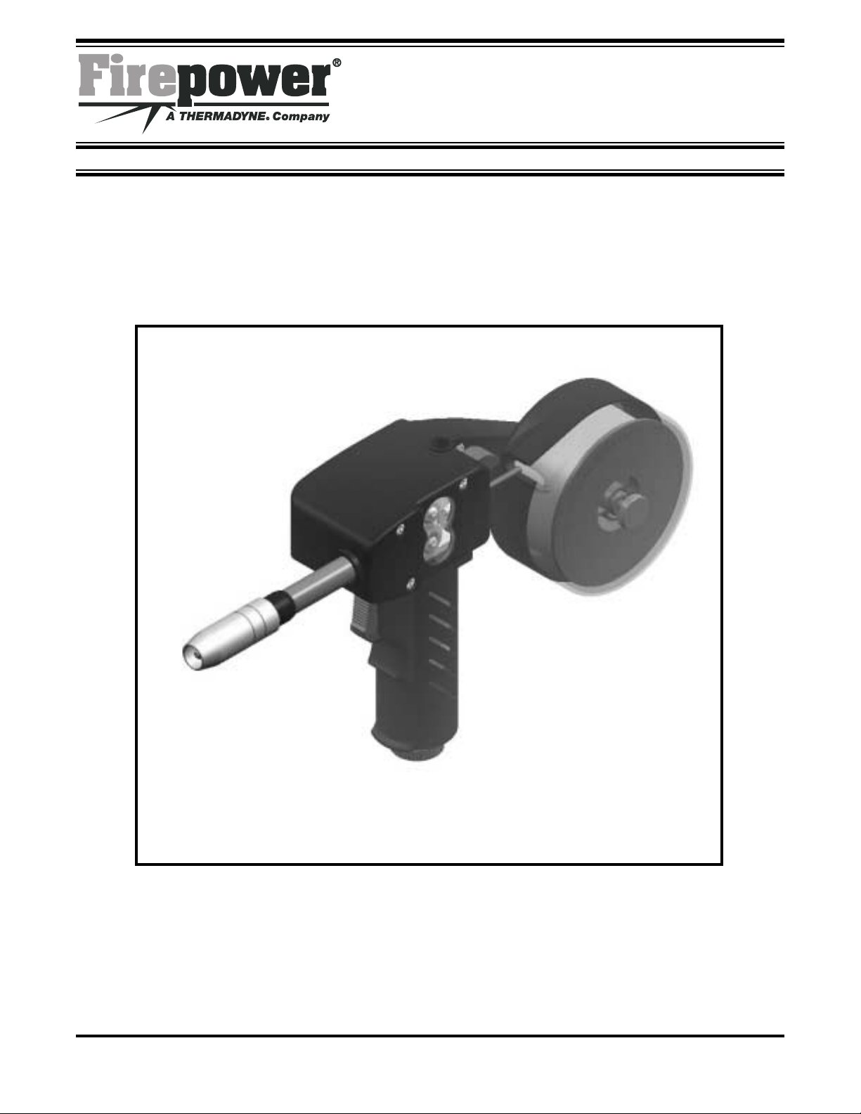
Modular Spool Gun for MIG Welding
Operating and Safety Instructions
For Your Safety....
PLEASE READ CAREFULLY!
IMPORTANT
Spool Gun
Operating and Safety Manual
Page 2

Firepower SPOOL GUN OPERATING AND SAFETY MANUAL
2
TABLE OF CONTENTS
1. Introduction.................................................................................................3
2. Safety Instructions........................................................................................5
3. Product Description......................................................................................9
4. Installation..................................................................................................10
1. Connecting Spool Gun to Power Source...........................................10
2. Installing Wire Spool.........................................................................11
3. Wire speed adjustment.....................................................................13
5. Maintenance..............................................................................................14
1. Controls............................................................................................14
2. Changing drive rolls..........................................................................15
3. Changing outlet liner........................................................................16
4. Troubleshooting Check List...............................................................17
6. Technical Data Sheet ..................................................................................18
7. Electric Connections...................................................................................19
8. Spare Parts Lists.........................................................................................20
9. Warranty....................................................................................................23
Page 3
Firepower SPOOL GUN OPERATING AND SAFETY MANUAL
3
Introduction
The Spool Gun is the best solution for situations where the power source can not be brought close
enough to your the work. The Firepower Spool Gun is a professional MIG gun suitable for welding
carbon steel, stainless steel or aluminum, using solid wire and also for flux cored wire. Wire is
driven by a DC electric motor in the gun, wire speed is controlled by an adjustable potentiometer
mounted in the base of the gun handle.
WARNING: Before attempting to connect, operate or adjust this product, please read this
instruction manual completely . Following these instructions carefully will facilitate the use of the
spool gun.
The 180 Amp Spool Gun
Page 4

Firepower SPOOL GUN OPERATING AND SAFETY MANUAL
4
Introduction
This User’s Guide provides pertinent information needed to safely and effectively use your
Firepower Spool Gun. It gives instructions on
set-up, installation and actual use of your
Firepower Spool Gun.
Safety Profile
Tradesmen respect the tools and equipment
with which they work. They are also aware
that tools and equipment are dangerous if
used improperly or abused.
NOTE: Read this guide prior to using
your Spool Gun. It enables you to do a bet-
ter and safer job. You will also learn the Spool
Gun’s application, limitations, and the specific
potential hazards peculiar to welding.
Safety Information
The following safety information is provided
to you as a guideline. Use it to operate your
new Firepower Spool Gun under the safest
possible conditions. Any equipment that uses
electrical power is potentially dangerous to
use when the safety or safe handling instructions are not known and/or are not followed.
This safety information gives you the necessary information for safe use and operation.
WARNING
Items in this manual that significantly affect
safety are identified with the following headings. Please read and understand this manual.
Pay special attention to items identified with
these headings.
WARNING – Means there is a poss-
ibility of injury or death to you or others.
CAUTION – Means there is the
possibility of damage to the Firepower
Spool Gun or other property.
NOTICE – Indicates point of interest for
more efficient and convenient installation or
operation.
Read all Safety and Warning Instructions
Carefully before attempting to install, operate
or service this welding unit. Your failure to
comply with the instructions could result in
personal injury and/or property damage.
IMPORTANT
RETAIN THESE INSTRUCTIONS FOR YOUR
FUTURE REFERENCE.
Page 5
Firepower SPOOL GUN OPERATING AND SAFETY MANUAL
5
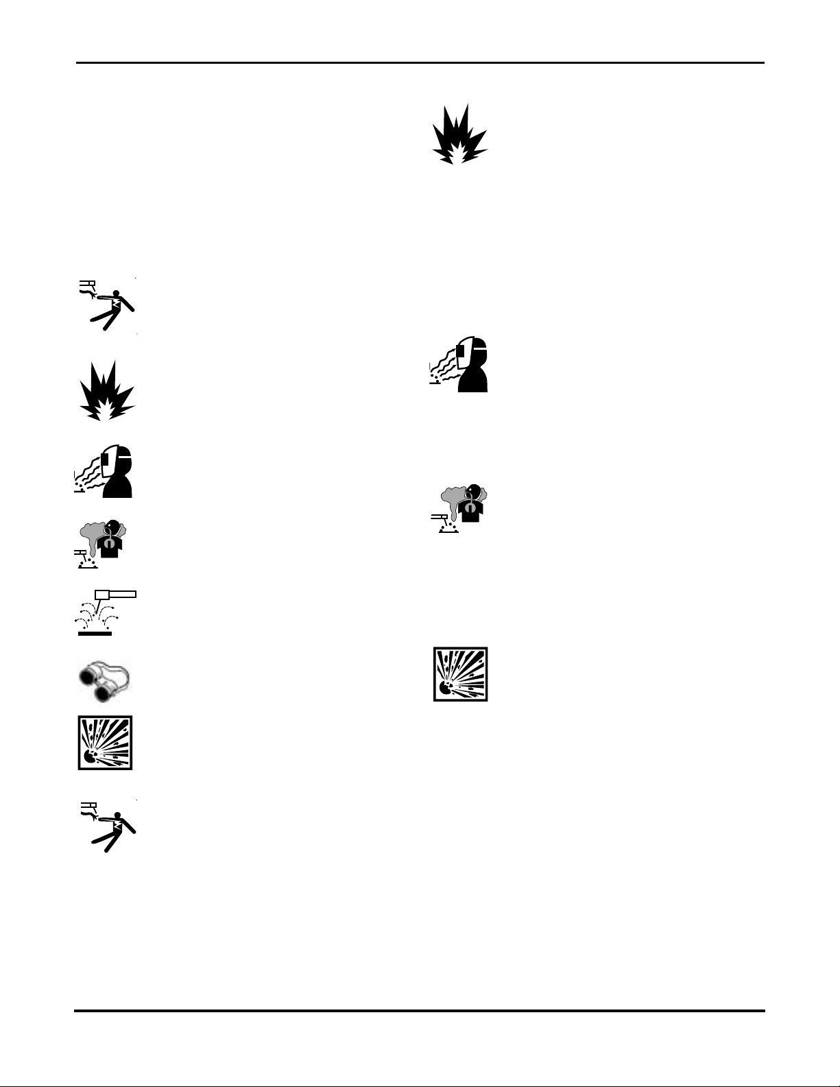
Safety Symbols
Familiarize yourself with the warning symbols
listed on the following pages. These symbols
identify important safety messages in this
manual. When you see one of these symbols,
be alert to the possibility of personal injury and
carefully read the message that follows.
I
ndicates that the possibility of ELECTRIC
SHOCK exists during the operation of the
step(s) that follow.
Indicates that the possibility of FIRE HAZ-
ARD exists during the step(s) that follow to
protect against eye damage and burns due
to flash hazard.
Indicates that the HELMET MUST BE WORN
during the step(s) that follow to protect
against eye damage and burns due to flash
hazard.
Indicates that the POSSIBILITY OF TOXIC
GAS hazard exists during operation of the
step(s) that follow.
Indicates that the POSSIBILITY OF BEING
BURNED by hot slag exists during operation
of the step(s) that follow.
Indicates that EYE PROTECTION SHOULD
BE WORN to protect against flying debris in
the following step(s).
Indicates that the POSSIBILITY OF INJURY
OR DEATH exist due to improper handling
and maintenance of compressed gas cylinders or regulators.
ELECTRIC SHOCK CAN KILL! Reduce the
risk of death or serious injury from shock:
Read, understand and follow the following
safety instructions. Additionally, make certain that anyone else who uses this welding
equipment, or who is a bystander in the
welding area, understands and follows these
safety instructions as well.
FIRE OR EXPLOSION CAN CAUSE DEATH,
INJURY AND PROPERTY DAMAGE! Reduce
the risk of death, injury or property damage
from fire or explosion. Read, understand and
follow the following safety instructions.
Additionally, make certain that anyone else
who uses this welding equipment, or who is
a bystander in the welding area, understands
and follows these safety instructions as well.
Remember, welding by nature produces
sparks, hot spatter, molten metal drops, hot
slag and hot metal parts that can start fires,
burn skin and damage eyes.
ARC RAYS CAN INJURE EYES AND BURN
SKIN! Reduce the risk of injury from arc
rays. Read, understand and follow the following safety instructions. Additionally,
make certain that anyone else who uses this
welding equipment, or who is a bystander in
the welding area, understands and follows
these safety instructions as well.
FUMES, GASES AND VAPORS CAN CAUSE
DISCOMFORT, ILLNESS AND DEATH!
Reduce the risk of discomfort, illness or
death. Read, understand and follow the following safety instructions. Additionally,
make certain that anyone else who uses this
welding equipment, or who is a bystander in
the welding area, understands and follows
these safety instructions as well.
IMPROPER HANDLING AND
MAINTENANCE OF COMPRESSED GAS
CYLINDERS AND REGULATORS CAN
RESULT IN SERIOUS INJURY OR DEATH!
Reduce the risk of injury or death from compressed gases and equipment hazards. Read,
understand and follow the following safety
instructions. Additionally, make certain that
anyone else who uses this welding equipment, or who is a bystander in the welding
area, understands and follows these safety
instructions as well.
Page 6

Firepower SPOOL GUN OPERATING AND SAFETY MANUAL
6
Health Hazards
The welding process can be hazardous to your
health. Therefore, follow these precautions:
1. ALWAYS wear protective clothing without
pockets and cuffs. Wear a helmet, gloves
and shoes with an insulating sole.
2. ALWAYS use a welding mask or helmet
with the properly tinted protective glass in
the shade adequate to the welding operation being performed and to the current
intensity.
3. Make certain that bystanders in the welding area are also following these precautions.
4. ALWAYS keep the welding mask glass
clean. Replace it if it is cracked or chipped.
5. NEVER weld in a damp area or come in
contact with a moist or wet surface when
welding.
6. If the welding area lacks proper ventilation,
use fume extractors.
7. Clean the welding pieces of solvents or
grease which develop toxic gases when
exposed to heat.
Electric Shock
WARNING Electric Shock Can Kill!
Reduce the risk of death or serious injury
from shock. Read, understand and follow
ALL safety instructions. Be sure that
everyone who uses this welding equipment or who is a bystander in the welding area understands and follows ALL
safety instructions as well.
WARNING Electric Shock Can Be Fatal.
A person qualified in First Aid techniques
should ALWAYS be present in the working area. If a person is unconscious and
electric shock is suspected, DO NOT
touch the person if he or she is in contact
with electric wires or touch leads.
Disconnect power from the machine,
then use First Aid. Use dry wood or other
insulating materials to move cables, if
necessary, away from the person.
1. Never touch or come in physical contact
with any part of the input current circuit
and welding current circuit.
2. Frequently check that the input cable and
plug are in good condition.
3. Make sure that the welder is disconnected from the main power supply BEFORE
attempting any repairs, opening the side
panels of the machine or repairing the
input cable.
4. Fit the main line BEFORE the distribution
outlet, with a three-pole switch with adequate delayed fuses (check the characteristics plate for fuse values).
5. DO NOT weld with cables, torch or earth
clamp in poor shape.
6. DO NOT coil the torch or the earth
cables around your body.
7. DO NOT point the welding torch against
yourself or against bystanders.
8. Should you feel the slightest electrical
shock, STOP welding IMMEDIATELY!
DO NOT use the welder until the fault is
found and resolved.
Page 7

Firepower SPOOL GUN OPERATING AND SAFETY MANUAL
7
General Welding
Safety Instructions
WARNING Welding processes of any
kind can be dangerous not only to the operator but to any person situated near the
equipment, if safety and operating rules are
not strictly observed.
Personal Protection
1. WARNING Wear closed, non-flam-
mable protective clothing, without pockets or turned up trousers.
2. WARNING Wear a non-flammable
welding helmet to shield the neck, face
and sides of the head. Keep the protective lens clean. Replace the protective
lens if broken or cracked. Position a
transparent glass between the lens and
the welding area. Weld in a well ventilated area that does not open into other
working areas.
3. WARNING Never look at the arc
without proper protection for the eyes.
4. WARNING Thoroughly clean metal
of rust or paint to avoid producing harmful fumes. Parts degreased with a solvent
must dry before welding.
5. WARNING Never weld on metals or
coated metals containing zinc, mercury,
chromium, graphite, lead, cadmium or
beryllium unless the operator and the
people standing in the same area use an
air-supplied respirator.
Safety Instructions
For your safety, BEFORE connecting the power
source to the line, follow these instructions:
1. Insert an adequate two-pole switch,
equipped with time-delay fuses, before
the main outlet.
2. Make the single-phase connection with a
two-pole plug compatible with the above
mentioned socket.
3. The two wires of the two-pole input
cable are used for the connection with
the single-phase line. The yellow/green
wire is for the compulsory connection to
the ground in the welding area.
4. When working in a confined space, keep
the power source outside the welding
area and fix the ground cable to the
workpiece. Never work in a damp or wet
area.
5 DO NOT use damaged input or welding
cables.
6. WARNING NEVER operate the
power source without its panels in place.
This could cause serious injury to the
operator and could damage the equipment.
Page 8

Firepower SPOOL GUN OPERATING AND SAFETY MANUAL
8
Fire Prevention
Welding operations use fire or combustion as a
basic tool.
1. The work area MUST have a fireproof
floor.
2. Work benches or tables used during
welding operations MUST have fireproof
tops. DO NOT weld on wooden work
benches.
3. Use heat-resistant shields or other
approved material to protect nearby walls
or unprotected flooring from sparks and
hot metal.
4. Keep an approved fire extinguisher of the
proper size and type in the work area.
Inspect it regularly to ensure that it is in
proper working order. Know how to use
the fire extinguisher.
5. Remove all combustible materials from
the work site. If you can not remove
them, protect them with fireproof covers.
WARNING NEVER perform welding
operations on a container that has held toxic,
combustible or flammable liquids or vapors.
NEVER perform welding operations in an
area containing combustible vapors, flammable liquids or explosive dust.
Ventilation
WARNING Ventilate welding work areas
adequately. Maintain sufficient air flow to
prevent accumulation of explosive or toxic
concentrations of gases. Welding operations
using certain combinations of metals, coatings and gases generate toxic fumes. Use
respiratory protection equipment in these circumstances. BEFORE welding, read and
understand the Material Safety Data Sheet
for the welding alloy.
Electromagnetic Compatibility
BEFORE installing a MIG power source,
inspect the surrounding area checking the
following points:
1. Make sure there are no other power supply cables, control lines, telephone cables
or other devices close to the power
source.
2. Make sure that telephones, televisions,
computers or other control systems are
not in the working area.
3. People with pace-makers or hearing aides
should keep far from the power source.
In particular cases, special protection
measures may be required.
Reduce interference by following these suggestions:
1. If there is interference in the power
source line, mount an E.M.T. filter
between the power supply and the
power source.
2. Shorten the output cables of the power
source, keep them together and connected to ground.
3. Securely fasten the panels of the power
source in place after performing maintenance.
Page 9

Firepower SPOOL GUN OPERATING AND SAFETY MANUAL
9
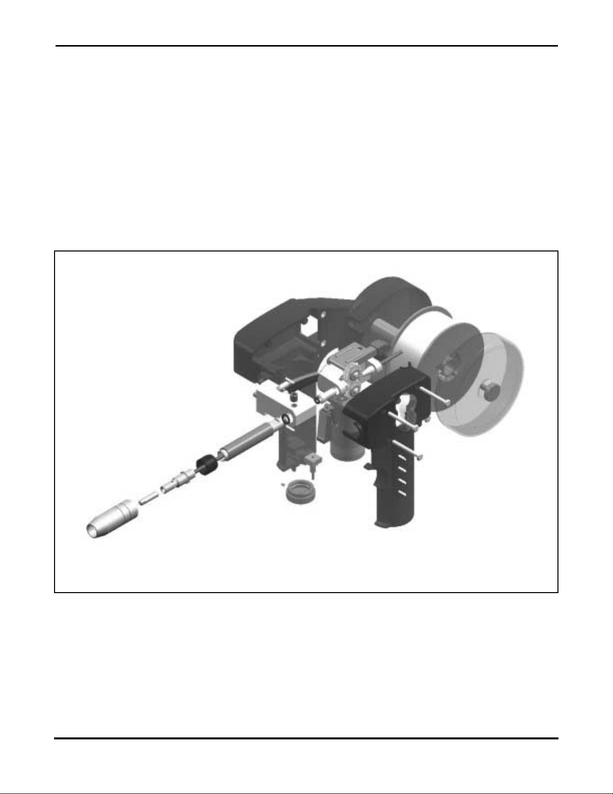
3. Product Description
Drive roll pressure
adjustment screw
Wire Spool
Wire tension
adjustment nut
Drive Rolls
Trigger
Drive roll pressure release lever
Nozzle
Wire Speed Adjustment
(Potentiometer)
Cable
Figure 1
Page 10

Firepower SPOOL GUN OPERATING AND SAFETY MANUAL
10
4. Installation
The manufacturer will not be responsible for damages caused by incorrect installation. Any
service required due to incorrect installation will not be covered by the warranty.
4.1. Connecting Spool Gun to the Power Source
The Spool Gun is provided with two connectors:
• Connection for power cable, gas hose, liner, and trigger.
• 6 pin connector for motor power and wire speed control.
1. Before connecting the Spool Gun,
switch off the power source.
2. Connect spool gun Euro Connect
adapter to power source terminal and
rotate the lock ring clockwise until it is
firmly locked. (Do not over tighten)
3. Connect spool gun 6 pin connector to
power source terminal and rotate the
lock ring clockwise until it is firmly
locked. (Do not over tighten)
4. Once the connections have been made
properly, switch the power source on.
For more information please refer to spool
gun electric schematic (see page 19).
Figure 2
Figure 3
Page 11

Firepower SPOOL GUN OPERATING AND SAFETY MANUAL
11
1. Before operating on the torch, switch off
the welder.
2. Remove nozzle.
3. Make sure that liner and contact tip
match with diameter of welding wire.
4. Remove any burrs or sharp points from
end before fitting into torch.
5. Open the wire spool cover and insert
the spool into spool shell (wire feeds
from top).
6. Adjust the friction nut on the spool shaft
to find the correct wire tension
4.2. Installing Wire Spool
For the choice of right contact tip and wire please refer to spool gun data sheet (see par.6.)
Page 12

Firepower SPOOL GUN OPERATING AND SAFETY MANUAL
12
7. Thread wire into inlet liner
8. Push and hold red drive roll pressure
release lever
9. Thread wire to the middle of drive rolls
10. Release red lever
11. Replace the spool cover and switch the
power source on
12. Turn the wire speed adjustment to
minimum wire speed (see page 13 )
13. Press gun trigger to feed wire through
outlet liner and out the end of the
contact tip 2” (50mm).
WARNING — Never place finger over
end of gun. Wire may be driven through
finger
14. Install nozzle
15. Pressing gun trigger to feed wire, adjust
the drive roll pressure to provide smooth
wire travel without crushing the wire.
16. Cut off wire
Page 13

Firepower SPOOL GUN OPERATING AND SAFETY MANUAL
13
4.3. Wire speed adjustment
1. Turn wire speed adjustment to minimum
wire speed
2. Start welding by pressing the trigger.
3. Increase wire speed to achieve the
desired arc by turning the wire speed
adjustment clockwise.
Page 14

Firepower SPOOL GUN OPERATING AND SAFETY MANUAL
14
5. Maintenance
5.1 Controls
Before you maintain or replace spool gun
parts, turn the power source off.
Replace contact tip if hole is enlarged or
deformed. Always make sure to use the
correct diameter for the wire
Replace liner if hole is obstructed. Smooth
head of liner.
Periodically clean inside of nozzle and holes of
gas diffuser. Use an anti-spatter spray.
Periodically clean drive rolls.
Check condition of cable. Do not make
temporary repairs. Repairs should only be
made by qualified personnel.
Do not bend cables and hoses too tightly, to
avoid damage that may prevent gas from
flowing freely.
Repairs must be done only by skilled and
qualified personnel.
Used parts should be recycled in a proper way,
meeting the local requirements.
Page 15

Firepower SPOOL GUN OPERATING AND SAFETY MANUAL
15
1. Be sure to select replacement drive rolls
to match the wire diameter to be used.
NOTE that the lower drive roll is slotted
for the key.
2. Before removing the transparent drive
roll cover, turn off the power source.
3. Remove the transparent drive roll cover.
4. Relieve pressure on the drive rolls by
pressing down the red lever.
5. Changing upper drive roll: Remove
screw and washer and lift out the drive
roll. Slide the new drive roll onto shaft
and secure with washer and screw.
6. Changing lower drive roll: Remove
screw and washer and lift out the drive
roll. (NOTE - the key will normally come
out with the drive roll, be careful not to
lose the key.) Place the key in the shaft
slot and slide the new drive roll onto the
shaft. Secure with washer and screw.
7. Reinstall the transparent drive roll cover.
5.2. Changing drive rolls
Page 16

Firepower SPOOL GUN OPERATING AND SAFETY MANUAL
16
5.3. Changing outlet liner
1. Remove the gas nozzle and the contact
tip from the gun tube
2. Pull the liner out of the gun tube
3. Make tip of liner round before fitting
into torch. NO SHARP EDGES.
4. Carefully insert the new liner into the
gun tube of the torch.
5. Install the contact tip and the gas nozzle
onto the end of the gun tube
Page 17

Firepower SPOOL GUN OPERATING AND SAFETY MANUAL
17
5.4. Troubleshooting Check List
Incorrect drive rolls
pressure
Drive rolls turn but wire
will not feed or wire
feeding is rough
Incorrect drive rolls
Be sure the wire diameter
being used is stamped on
drive rolls. Replace drive rolls
if necessary
Check and correct drive roll
pressure. Turn pressure
adjusting screw clockwise,
enough to prevent slipping.
(see page 11)
Worn or dirty drive rolls
Clean or replace drive rolls
(see page 15)
Incorrect wire spool friction
Adjust the friction nut on the
spool shaft to find the correct
wire tension (see page 11)
Worn or dirty outlet liner
Clean or replace liner (see
page 16)
Rusty or dirty wire Replace wire (see page 11)
Partially flashed, melted or
improper size contact tip
Replace contact tip
Variable arc
Contact tip worn or
incorrect size
Replace contact tip
Incorrect wire feeder
speed
Adjust wire speed by turning pot ring clockwise (to
max) or counter-clockwise
(to min). (see page 13)
Trouble
Possible cause
Remedy
Page 18

Firepower SPOOL GUN OPERATING AND SAFETY MANUAL
18
6. Technical Data Sheet
WELDING PARAMETERS
Welding current 150 A
Duty cycle 60 %
Cooling Gas
Power cable size 16 mm
2
Gas Argon - 100%
CONSUMABLES
Gas Diffusor TW 1
Gas Nozzle diameter 1/2"
Contact tip diameter as required
WIRE FEEDER
Voltage supply 24 V DC
Power 16 W
Average current draw 1-15 A
RPM (motor) 6000 RPM
Gear ratio 1:20
RPM (drive roll) 300 RPM
Wire feeder speed
Adjustable
1kOhm potentiometer
Max wire feeder speed
780 in./min.
(20m/min.)
.030" –.040"
(.08 – 1.0mm )
Maximum spool size
Diameter: 4” (100mm)
Width: 1.75"(45mm)
Overall dimensions
Length: 360mm (14.2”)
Width: 90mm (3.5”)
Height: 195mm (7.7”)
Net Weight (without spool) 2.5 lb. (1.15 kg)
OPTIONS
.023" (0.6mm)
Wire diameters for standard drive rolls
Drive rolls for steel and flux core wire
Drive rolls for aluminum wire
.045" (1.2mm)
.030/.035" (0.8/0.9mm)
.045" (1.2mm)
Page 19

Firepower SPOOL GUN OPERATING AND SAFETY MANUAL
19
7. Electric Connections
Six Pin Connector
Euro Connector
Euro Connector
Two Wires for Torch Trigger
Torch Trigger
Wiring for MIG Spool Gun With Speed Regulation On The Handle
Page 20

Firepower SPOOL GUN OPERATING AND SAFETY MANUAL
20
8. Spool Gun Spare Parts List
8.1 Table 1 – Gun Case
Ref # P/N Description
1 1444-0051 Gas Nozzle 1/2”
2 1444-0025 Contact Tip .023”
2 1444-0026 Contact Tip .030”
2 1444-0027 Contact Tip .035”
2 1444-0028 Contact Tip .040”
2 1444-0029 Contact Tip. 045”
2 1444-0030 Contact Tip. 045” Aluminum
3 1444-0080 Gas Diffuser
4 1444-0619 Insulator Torch Body
5 1444-1620 Red Teflon Liner
6 1444-1621 Neck Cover
7 1444-0622 Neck
8 1444-0623 0-Ring
9 1444-0624 Neck Screw
10 1444-0636 Block
11 1444-0637 O-Ring
12 1444-0638 Sleeve
13 1444-0639 Nut
14/15/16/18 1444-0640 Rolls Assembly Accessories
17 1444-0625 Set/Drive Roller for .023” Wire (Small)
17 1444-0626 Set/Drive Roller for .030” and .040 Wire Standard (Medium)
17 1444-0627 Set/Drive Roller for .030” and .040 Wire Aluminum (Medium)
17 1444-0628 Set/Drive Roller for .045” Wire Standard (Large)
17 1444-0629 Set/Drive Roller for .045” Wire Aluminum (Large)
19 1444-0630 Wire Feed (Ratio 1:20)
20 1444-0631 Kit Handle
21 1444-0632 Rubber Sleeve
22 1444-0641 Friction Spacer
23 1444-0642 Friction Nut
24 1444-0643 Spool Cover
25 1444-0644 Wire Guide
26 1444-0645 Drive Rolls Cover
27 1444-0646 Handle Screw
28 1444-0647 Switch Assembly
29 1444-0648 Trigger/Potentiometer Connection Cable
30 1444-0649 Potentiometer 1kOhm
31 1444-0650 Potentiometer Knob
8.2 Table 2 – Cable Assembly and Central Adapter
Ref # P/N Description
A 1444-0651 Complete Cable
B 1444-0652 Gas Hose
C 1444-0653 Current Cable 16mm26m
D 1444-0654 Control Cable
E 1444-0655 Back Box
F 1444-0656 Box Screw
G 1444-0657 Gun Plug Nut
H 1444-0658 Euro Central Adaptor Body
J 1444-0659 Connector
8.3 Table 2 – Accessories
Ref # P/N Description
K
1444-0660 20 Feet Power Cable Extension
To maintain the performance of your Spool Gun, use only original manufacturer’s suggested spare parts listed
above.
Page 21

Firepower SPOOL GUN OPERATING AND SAFETY MANUAL
21
Page 22

Firepower SPOOL GUN OPERATING AND SAFETY MANUAL
22
Page 23

Firepower SPOOL GUN OPERATING AND SAFETY MANUAL
23
FIREPOWER LIMITED WARRANTY
SCOPE OF LIMITED WARRANTY:
Firepower, a division of Thermadyne Industries, Inc. (hereinafter, “Seller”) warrants that its products are free
of defects in workmanship, or material. If an authorized distributor or the customer of an authorized distributor (hereinafter, collectively, “Purchaser”) who purchases Seller’s product, notifies Seller within the time set
forth below that the product has a defect in workmanship or material even though it has been stored,
installed, operated, and maintained in accordance with Seller’s specifications, instructions, recommendations
and in accordance with recognized standard industry practice, and the product was not misused, repaired,
neglected, altered, or damaged, the Seller may repair or replace, in its sole discretion, those parts of the product determined by Seller to be defective in workmanship or material if said defect is not attributable to
Purchaser’s acts or omissions.
THIS WARRANTY EXCLUDES ANY WARRANTY OF MERCHANTABILITY, FITNESS FOR A PARTICULAR PURPOSE, OR OTHER WARRANTY OF QUALITY, WHETHER EXPRESSED, IMPLIED OR STATUTORY.
LIMITED WARRANTY PERIOD: Except as otherwise limited below, this limited warranty is effective for twelve
months from the date Seller sells the product to an authorized distributor, or for twelve months after an
authorized distributor sells the product to its customer, whichever is longer, except that in no event will this
warranty exceed eighteen months from the date the product is sold from Seller to an authorized distributor.
Notwithstanding the foregoing:
• Firepower oxygen / acetylene products will be covered by a two-year product replacement warranty
• Firepower plasma cutting equipment will be covered by a one-year (parts & labor) warranty.
• Firepower Spool Gun will be covered by a limited one-year warranty
• Firepower engine-driven welding machines will be covered by a one-year (parts & labor) warranty.
Engines will be covered by the manufacturer’s warranty.
• Firepower ADF (auto-darkening) welding helmets will be covered by a one-year warranty. Any ADF hel-
met claims must be made directly to Jackson / Morsafe products, Belmont, MI 800-253-7281.
• Firepower welding electrodes, MIG (& flux cored) wire, and brazing rods, although manufactured to AWS
Class specifications, are considered perishable items. As such, these products are sold “as is” and “with
faults” and without warranty, either express or implied, including the warranties of merchantability and
fitness for a particular purpose.
• Products used in rental applications are warranted for one year from the date sold by the Seller to an
authorized distributor, without regard to when they were later sold by the authorized distributor.
LIMITED WARRANTY CLAIM METHOD: To make a claim under this warranty, Purchaser must notify Seller of
the details of such claim within thirty days of discovering a defect in material or workmanship. If the claim is
covered by this warranty, Seller will direct Purchaser to return the product to an authorized warranty repair
center. The Seller will not be responsible for transportation costs or risks of any kind under this warranty. The
Purchaser will be responsible for all such transportation, costs and risks.
LIMITATION OF LIABILITY: Seller shall not, under any circumstances, be liable for special, indirect, incidental
or consequential damages (regardless of the form of action, whether in contract or in tort including negligence), including, but not limited to, damage or loss of other property or equipment, loss of profits or revenue, cost of capital, cost of purchased or replacement goods, or claims of Purchaser for service interruption.
In no event will this warranty obligate Seller for any amount exceeding the price of the goods upon which liability is based. Correction of non-conformities, in the manner and time provided herein, constitutes fulfillment
of all Seller’s obligations to Purchaser with respect to Purchaser’s purchase of Seller’s product.
This warranty is invalid if the product was sold by non-authorized entities. This warranty is invalid if replacement parts or accessories were used that in the Seller’s sole opinion impaired the safety or performance of
Seller’s product. This warranty supersedes all previous warranties.
Page 24

24
WORLD HEADQUARTERS: 101 S. Hanley Road • St. Louis, MO 63105 • 314-721-5573 • Fax 314-721-4822 THERMADYNE®
Victor Equipment Company
U.S.A.
Customer Service
P.O. Box 1007
Denton, TX 76202-1007
800-382-8187
FAX 800-535-0557
International
Customer Service
2070 Wyecroft Road
Oakville, Ontario L6L5V6
Canada
905-827-9777
FAX 905-827-9797
Canada
Customer Service
2070 Wyecroft Road
Oakville, Ontario L6L5V6
Canada
905-827-1111
FAX 905-827-3648
Europe
Europa Building
Chorley North Industrial Park
Chorley, PR6 7BX, England
44-1257-261755
FAX 44-1257-261756
Asia/Pacific PTE, Ltd.
Hillview House Units 401-403
1 Jalan Remaja
Singapore 2366
65-763-4022
FAX 65-763-5812
Mexico
Calle de Zaragoza #25
Col. Santa Cruz Atoyac
C.P. 03910 Mexico, D.F.
52-5-605-8408
FAX 52-5-604-9671
Form No. 0056-1867 (6/01) © Victor Equipment Company, 2001 Printed in U.S.A.
The Quality System of the Denton and Abilene, Texas, locations of
Victor Equipment Company, Victor de Mexico in Hermosillo, Mexico and Victor de
Brazil in Rio de Janeiro, Brazil, are registered by Det Norske Veritas (DNV), to meet
the requirements of ISO-9001, 1994
 Loading...