

Page 1
Manual 0-2761
RPT Adapter Kit
Catalog # 7-3437
General Information
Installation Instructions
This Replacement Torch Adapter Kit is to be used to connect the Thermal Dynamics Plasma RPT Series Cutting Torch to the
following equipment:
• MUL TIQUIP MQ PCX50SS
• OTC D-5000 and D-7000
• P-TRON 75 and 100
• MRAT-70
Parts Supplied
The following parts are included in this kit:
• Control Connector Plug with Connectors (1 ea)
• Dummy Connector Plug (1 ea)
Installation
Install the Adapter Kit per the following procedure:
1. Turn OFF the power supply.
2. Disconnect the main input power to the power supply.
3. Remove the existing torch from the power supply, removing covers as required.
4. Install the Dummy Connector Plug provided into the Power
Supply.
5. Connect the pilot wire (+) from the replacement tor ch to the
Power Supply and tighten securely
For Mechanized Systems refer to the
T or ch Control Cable Wiring Diagram
on the last page of this Manual.
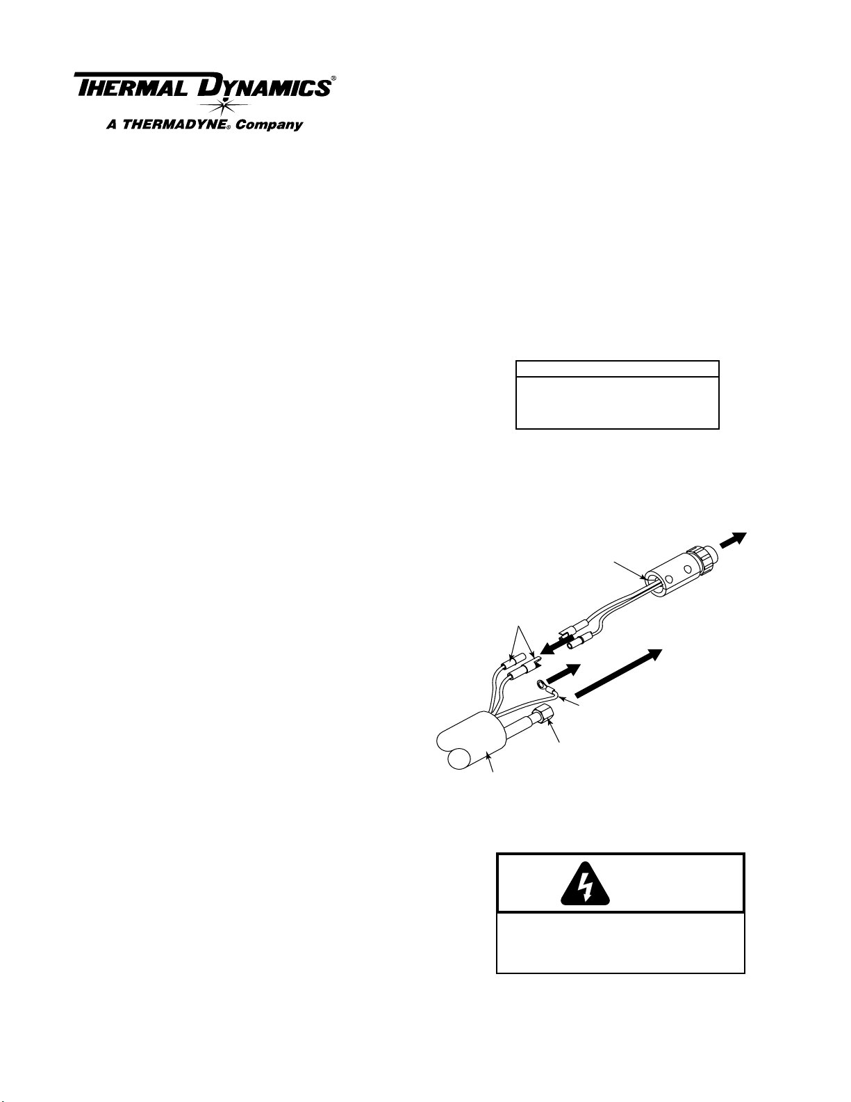
Control Connector
Plug with Connectors
NOTE
To Power Supply
Control Connector
6. Connect the Negative/Plasma Lead from the replacement
torch to the Power Supply. Slide the protective boot over
the lead connection.
7. Connect the Negative/Plasma Lead from the replacement
torch to the Adapter Fitting.
8. Connect the Control Connector Plug (see NOTE), with two
connectors, to the two mating connectors on the replacement
torch leads.
9. Connect the Control Connector Plug to the Power Supply.
10. Reinstall any covers removed (see WARNING).
11. Install the proper torch consumables for the Power Supply
amperage.
12. Reconnect main input power to the Power Supply and turn the unit
ON.
13. Set air pressure to 60 - 70 psi (4.1 - 4.8 bar).
14. Test torch for proper operation.
Torch Control
Connectors
Negative/Plasma Lead
Torch Lead Assembly
Make sure that the Control Connector Plug wires
DO NOT contact the Adapter Fitting after all
leads are connected.
To Power Supply
Pilot Connector
Pilot Lead
WARNING
To Power Supply
(-) Fitting
A-02487
© 1998 Thermal Dynamics Corp., Printed in USA 1 Installation Instructions 12/7/00
Page 2
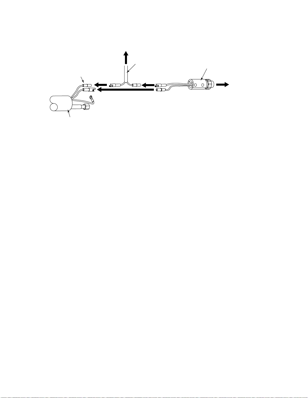
Torch Control Cable Wiring Diagram For Mechanized Systems
T o Torch
Control Device
Control Connector
Plug with Connectors
Torch Control
Torch Control
Cable
Connectors
To Power Supply
Control Connector
A-02488
Torch Lead Assembly
NOTE
Every effort has been made to provide complete and accurate information in this manual. However, the
publisher does not assume and hereby disclaims any liability to any party for any loss or damage caused
by errors or omissions in this manual, whether such errors result from negligence, accident or any other
cause.
© 1998 Thermal Dynamics Corp., Printed in USA 2 Installation Instructions 12/7/00
 Loading...