

TW Audio VERA RF600 Assembly Instructions Manual
Assembly
Instructions
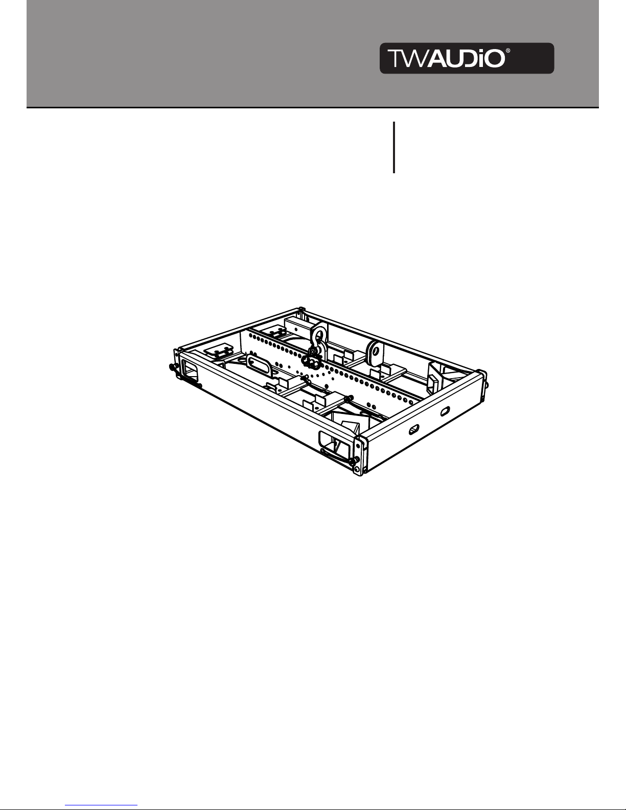
VERA RF600
Assembly Instructions VERA RF600
2
Introduction
Thank you for choosing a high-quality product “MADE IN GERMANY” from TW AUDiO.
The VERA RF600 rigging frame is an accessory for the VERA20 and VERA S32 loudspeakers.
It is characterized by a subtle look, a remarkable size to weight ratio and ease of use.
If you lend your product to another party, inform that party of the safety-related operating pro
cedures and hand over this operating manual. If you require additional copies of this manual,
you can obtain them free of charge from TW AUDiO or download them from: www.twaudio.de
Instructions in this setup manual
Strictly adhere to the instructions contained in this assembly guide that are marked as follows:
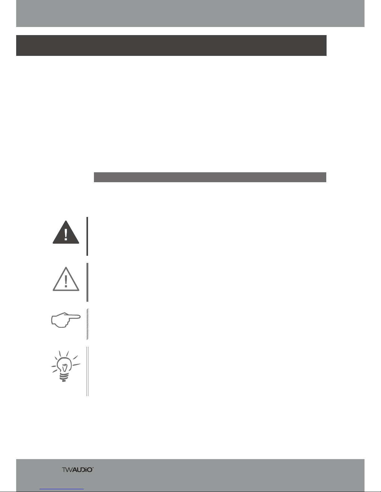
This symbol in combination with the signal word “Caution” identifies a potentially hazardous
situation. Failure to comply with this safety instruction can lead to light or moderate injury.
This symbol in combination with the signal word “Note” identifies a potentially hazardous situa
tion. Failure to comply with this safety instruction can lead to product damage.
This symbol in combination with the signal word “Tip” identifies additional information or notes
that will simplify working with TW AUDiO products on the basis of practical experience.
This symbol in combination with the signal word “Warning” identifies a potentially hazardous
situation. Failure to comply with this safety instruction can lead to serious injury or even death.
NOTE
TIP
CAUTION
WARNING

Assembly Instructions VERA RF600
3
Notes on the products
Read manual
before use!
Before using the rigging frame, carefully read the assembly instructions and keep the instructions in a safe place together with the VERA RF600 rigging frame.
General Information
Assembly Guide: OM-VERA RF600
Version 1.0 d, 06/2018
© by TW AUDiO 2018; all rights reserved.
All information contained in this assembly guide was correct to the best of our knowledge at
the time of printing.
Quality warranties or assurance of suitability for a certain type of use based on the technical
specifications, dimensions and weights are not granted by TW AUDiO.
TW AUDiO also shall not assume liability for any secondary damage (property damage and/or
personal injury) nor for the failure to comply with this assembly guide!
TW AUDiO reserves the right to update this document based on recent developments.
TW AUDiO GmbH
Osterholzallee 140-1
71636 Ludwigsburg
Phone: +49 7141 488989-0
Fax: +49 7141 488989-99

Assembly Instructions VERA RF600
4
Table of contents
1. Safety | Intended use........................................................................................................6
2. Overview...........................................................................................................................8
2.1. Scope of delivery....................................................................................................8
2.2 Placement of accessories for storage on the VERA RF600......................................9
3. Technical specifications.....................................................................................................9
3.1 Data sheet..............................................................................................................9
4. Commissioning...............................................................................................................10
4.1. Setup....................................................................................................................10
4.2. Preparing the VERA ORF900 outrigger set............................................................10
4.3. Assembly (rear): VERA ORF900 outrigger attached to VERA RF600 rigging frame..11
4.4. Assembly (front): VERA ORF900 outrigger attached to VERA RF600 rigging frame 12
4.5. Ground.................................................................................................................13
4.6. Alignment..............................................................................................................14
4.6.1. Step 1: front alignment...................................................................................14
4.6.2. Step 2: rear alignment....................................................................................14
4.6.3. Step 3: side alignment...................................................................................14
4.7. Pitfalls...................................................................................................................15
4.8. Danger of tipping over...........................................................................................15
4.9. Wind load..............................................................................................................15
4.10. Groundstack of the lowest VERA20 speaker.........................................................16
4.11. VERA20 groundstack setup, from the second speaker..........................................19
4.12. VERA S32 groundstack setup...............................................................................23
4.13. VERA S32 groundstack setup, from the second speaker.......................................27
4.14. Mixed VERA S32 and VERA20 groundstack setup................................................30
4.15. Preparing of VERA20 for rigging............................................................................33
4.16. Using the VERA LA900 load adapter in flown system.............................................35
4.17. Secondary safety component in the flown system.................................................37
4.18. Wind load in the flown system...............................................................................38
4.19. Flown system setup with VERA20 loudspeakers...................................................39

Assembly Instructions VERA RF600
5
4.20. Flown system setup with VERA20 loudspeakers, from the second speaker set.....45
4.21. Flown system setup with VERA S32 loudspeakers................................................53
4.22. Flown system setup with VERA S32 loudspeakers, from the second speaker........56
4.23. Flown mixed system setup with VERA20 and VERA S32 loudspeakers.................62
4.24. DE-Rigging a flown system with VERA20 loudspeakers.........................................68
4.25. DE-Rigging a flown system with VERA S32 loudspeakers.....................................81
4.26. DE-Rigging a flown mixed system with VERA20 and VERA S32 loudspeakers......87
5. Transport and Storage....................................................................................................90
6. EC - Declaration of Conformity........................................................................................91
7. Disposal..........................................................................................................................91
Assembly Instructions VERA RF600
6
1. Safety | Intended use
To avoid risks please observe the following safety instructions when using accessories.
The VERA RF600 rigging frame was developed for use in professional sound systems. The rigging
frame may only be used by trained and qualified personnel.
Damage caused by improper use is not covered by TW AUDiO.
Before each installation, check the integrity of the VERA RF600 rigging frame and ensure that all
components are in perfect condition.
The scope of delivery includes a specified load adapter with shackle. Only use this load adapter.
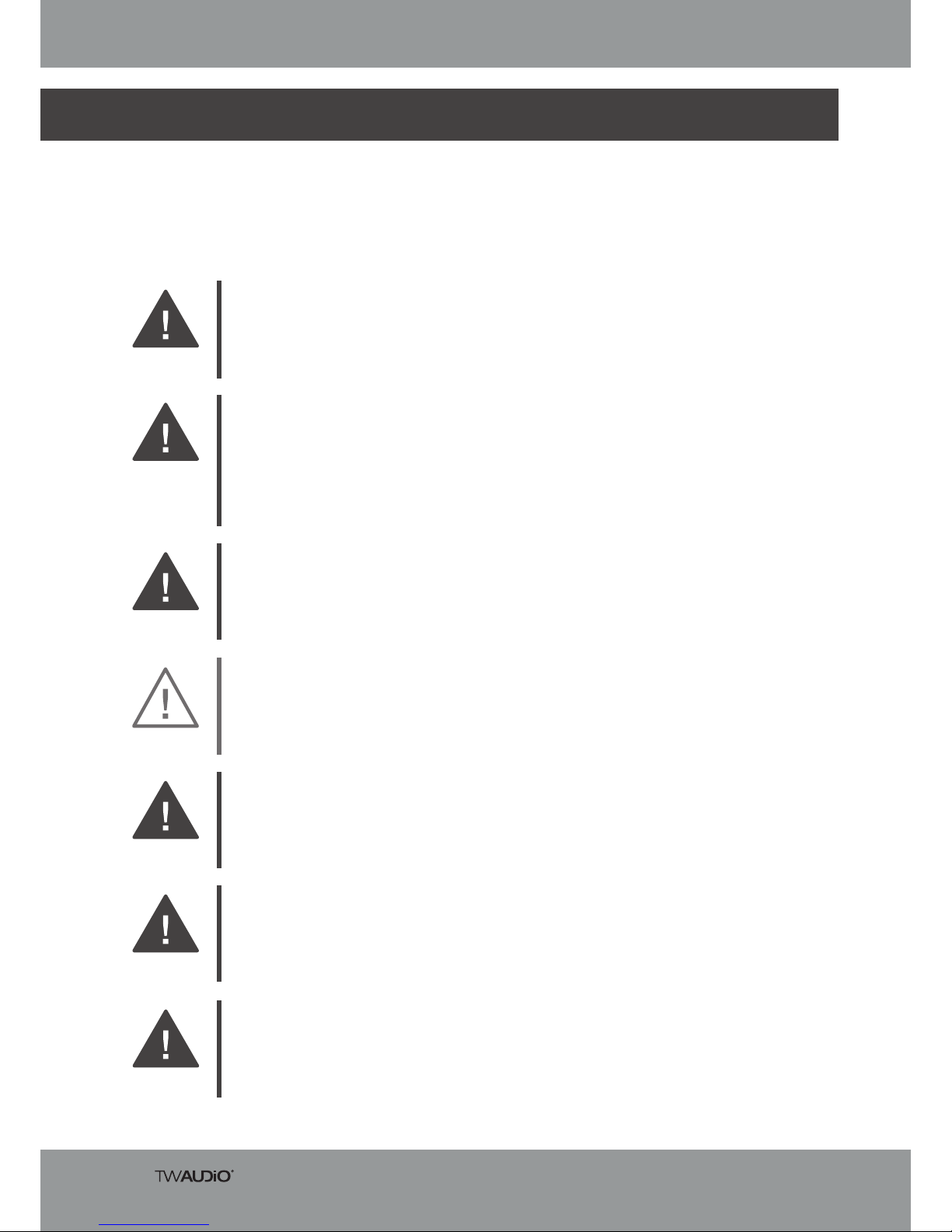
WARNING
The VERA RF600 rigging frame may only be used with the VERA20 and VERA S32 loudspeakers.
These assembly instructions describe how to use the VERA RF600 rigging frame. Any other use
shall be deemed improper and may result in damage or even injury.
Modifications or alterations to individual parts of the VERA RF600 rigging frame and the VERA LA900
load adapter are not permitted! Danger to life!
WARNING
During and after each system setup, check that all quick-lock pins are always completely inserted!
All quick-lock pins must always be used!
WARNING
The VERA RF600 is an accessory designed both for indoor and outdoor use.
CAUTION
The VERA RF600 rigging frame may only be used by trained and qualified personnel. Personnel
must check the VERA RF600 for its full suitability before each use.
WARNING
When visible damage to any part of the VERA RF600 rigging frame is detected, it must be decommissioned immediately.
WARNING
Before mounting the VERA RF600 rigging frame, all attachment points – such as ceilings and crossbeams – must be checked for full load capacity and stability.
The VERA RF600 accessory is specified for a load of not more than 24 (twenty-four) VERA20
loudspeakers or twelve (12) VERA S32 loudspeakers. This load capacity must never be exceeded!
WARNING
Assembly Instructions VERA RF600
7
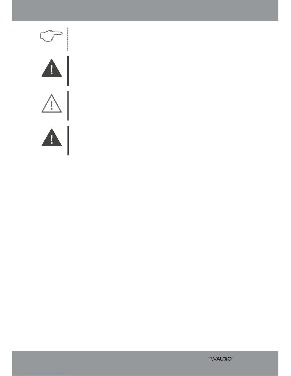
When moving (assembling, dismantling, maintaining) the VERA RF600 rigging frame with
VERA20 or VERA S32 loudspeakers, ensure sufficient space to prevent collisions with other
objects.
WARNING
When working with heavy loads exceeding 20 kg (44,09 lbs.), use suitable aids (dollies, hoisting
slings, etc.). Multiple persons may be required depending on the situation.
NOTE
When installing the VERA RF600 rigging frame, be careful not to pinch or twist the power cables
or other cables attached to the VERA20 or VERA S32 loudspeakers! The respective national
electrotechnical regulations apply.
CAUTION
All screw connections should be checked each time the VERA RF600 rigging frame is installed.
Tighten all loose screws. If this is no longer possible, the screws must be replaced.
WARNING

Assembly Instructions VERA RF600
8
1. VERA RF600 rigging frame – powder-coated surface
2. Load adapter with VERA LA900 shackle
3. Captive quick-lock pins
2. Overview
2.1 Scope of delivery
When the VERA RF600 rigging frame is delivered from the factory, the load adapter with the
VERA LA900 shackle and the quick-lock pins are in “Storage Position”.
NOTE
Figure 2.1 – Overview
1
3
3
3
3
2

Assembly Instructions VERA RF600
9
3. Technical specifications
2.2 Placement of accessories for storage on the VERA RF600
1. Outrigger VERA ORF900 for use with the VERA RF600 as a ground frame
2. Space for additional VERA LA900 load adapter
3. Angle sensor set VERA LAS900
Figure 2.2 - Overview
For storage, first insert all quick-lock pins through the mounting holes of the VERA ORF900 outrigger set and then through the mounting holes on the VERA RF600 rigging frame.
Make sure that each outrigger is securely attached to the VERA RF600 rigging frame.
WARNING
3.1 Data sheet
1
1
2
3
Assembly Instructions VERA RF600
10
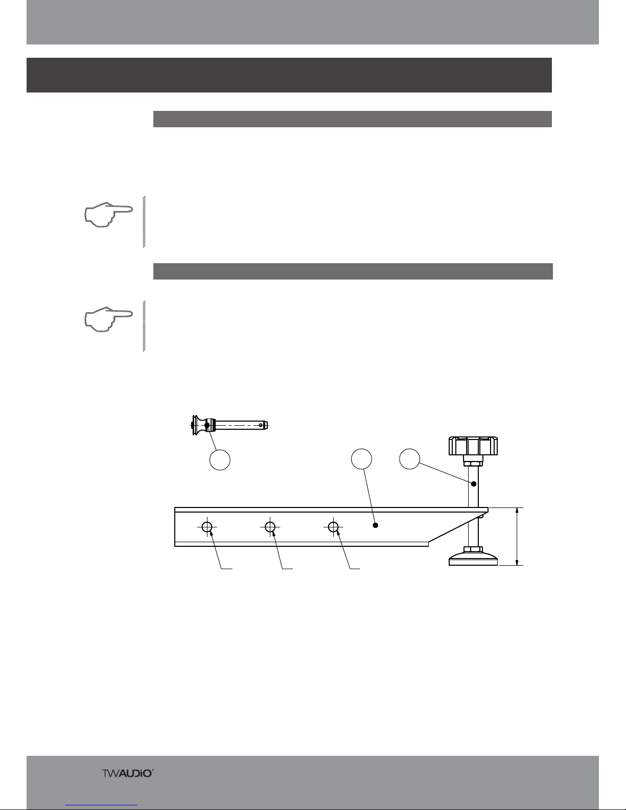
1. Outrigger
2. Spindle foot
3. Quick-lock Pin
4. Commissioning
4.1 Setup
The VERA ORF900 consists of four outriggers with spindle feet and quick-lock pins.
Screw all spindle feet of the VERA ORF900 outrigger set to the position indicated in figure 4.2.
NOTE
Figure 4.2 – ORF900 Outrigger
The VERA RF600 rigging frame is designed both for standing and hanging operation. TW AUDiO
provides a wide range of accessories to securely attach the rigging frame to crossbeams, motor
lifts, etc. in a suspended position.
TW AUDiO recommends using only the accessories specified by TW AUDiO for securing and moun
-
ting the rigging frame.
NOTE
4.2 Preparing the VERA ORF900 outrigger set
6
0
1 2
3
A B C
Assembly Instructions VERA RF600
11
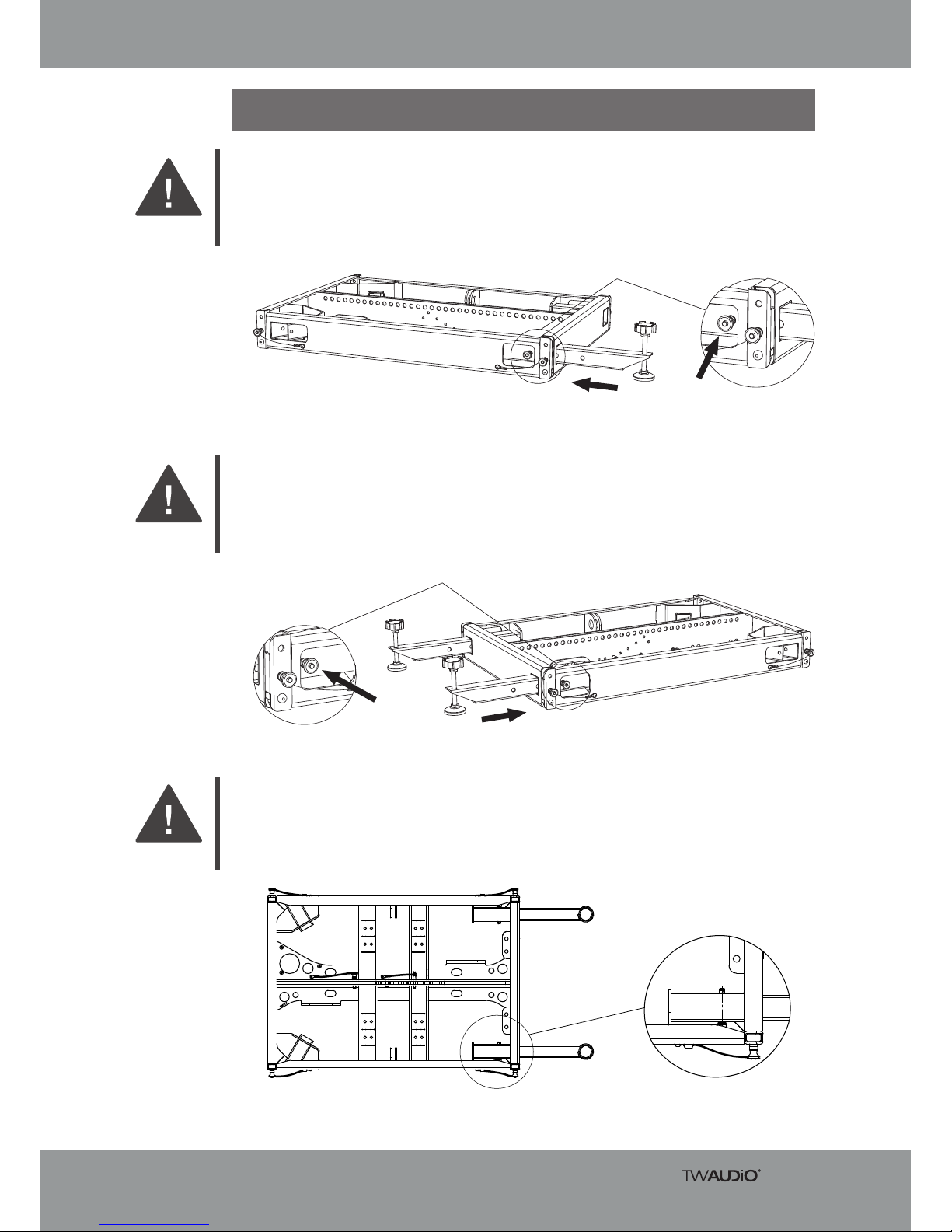
4.3 Assembly (rear): VERA ORF900 outrigger attached to VERA RF600 rigging
frame
Figure 4.3.1 – Rear-mounting the VERA ORF900 outrigger on the VERA RF600
1. Insert the first outrigger into the square tube on the VERA RF600 rigging frame at the rear
left position. Attach the outrigger to the rigging frame by means of a quick-lock pin. If
possible, use the outermost mounting hole A on the outrigger.
WARNING
2. Insert the second outrigger into the square tube on the VERA RF600 rigging frame at the
rear right position. Attach the outrigger to the rigging frame by means of a quick-lock pin.
If possible, use the outermost mounting hole A on the outrigger.
WARNING
Figure 4.3.2 – Rear-mounting the VERA ORF900 outrigger on the VERA RF600
3. Always insert all quick-lock pins completely through all square tubes
(see Figure 4.3.3 right).
WARNING
Figure 4.3.3 – Rear-mounting the VERA ORF900 outrigger on the VERA RF600
Assembly Instructions VERA RF600
12
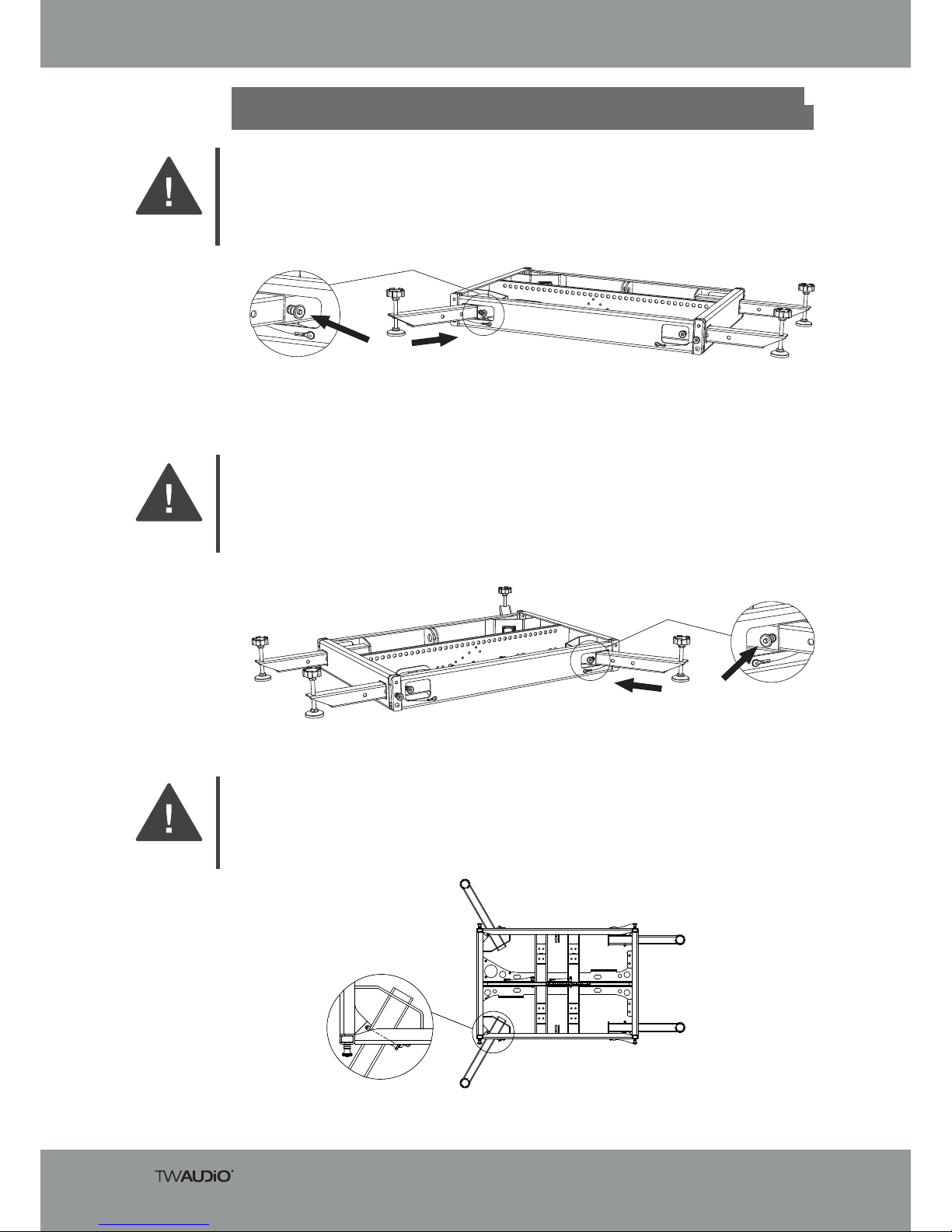
4.4 Assembly (front): VERA ORF900 outrigger attached to VERA RF600 rigging
frame
Figure 4.4.1 – Front-mounting the VERA ORF900 outrigger on the VERA RF600
1. Insert the third outrigger into the square tube on the VERA RF600 rigging frame at the
front left position. Attach the outrigger to the rigging frame by means of a quick-lock pin.
If possible, use the outermost mounting hole A on the outrigger.
WARNING
2. Insert the fourth outrigger into the square tube on the VERA RF600 rigging frame at the
front right position. Attach the outrigger to the rigging frame by means of a quick-lock pin.
If possible, use the outermost mounting hole A on the outrigger.
WARNING
Figure 4.4.2 – Front-mounting the VERA ORF900 outrigger on the VERA RF600
3. Always insert all quick-lock pins completely through all square tubes
(see Figure 4.4.3 left).
WARNING
Figure 4.4.3 – Front-mounting the VERA ORF900 outrigger on the VERA RF600
Assembly Instructions VERA RF600
13
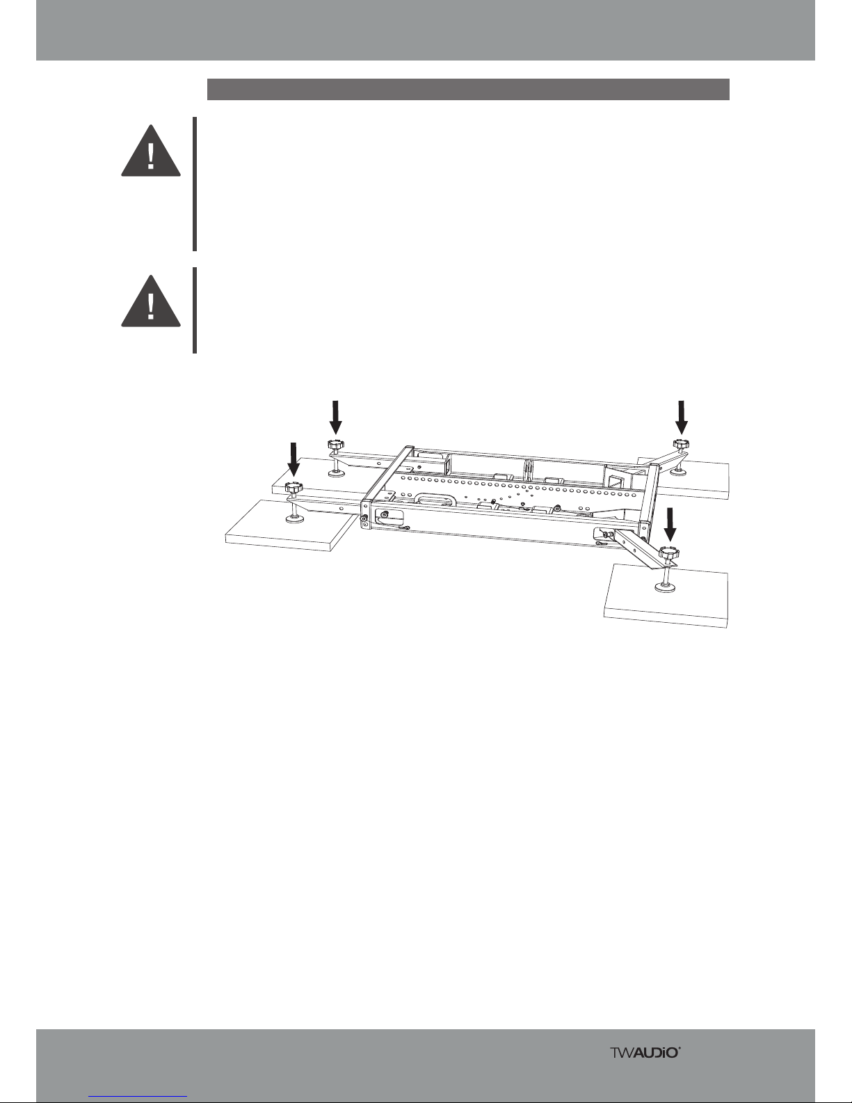
4.5 Ground
Figure 4.5.1 – Rigging frame resting only on the spindle feet
1. When setting up a system on uneven surfaces, such as gravel or grass, always put a
pressure-resistant surface under all four spindle feet!
Make sure that all four spindle feet rest completely on the pressure-resistant shims and
that the surface can withstand the total weight.
Note that depending on the system design, either the front or rear spindle feet may be able
to carry more weight.
WARNING
2. Turn all four Outrigger spindle feet until the VERA RF600 rigging frame is completely lifted
off the ground. The rigging frame itself must not be in contact with the ground.
WARNING
Assembly Instructions VERA RF600
14
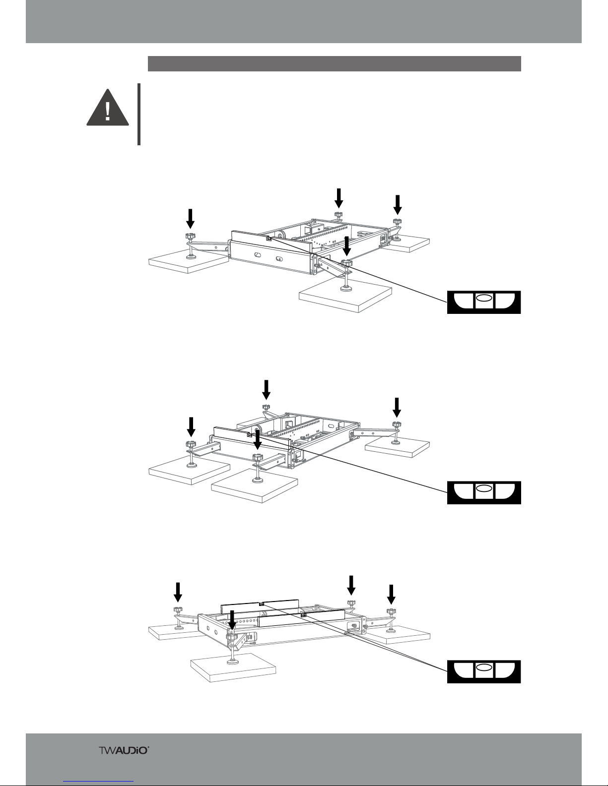
4.6 Alignment
Figure 4.6.1.1 – Rigging frame front alignment
Always level the VERA RF600 rigging frame using a spirit level before commencing system construction. To do so, turn the spindle feet.
Make sure that the VERA RF600 rigging frame rests completely on the spindle feet.
WARNING
Follow these steps:
4.6.1 Step 1: Front alignment
4.6.2 Step 2: Rear alignment
Figure 4.6.2.1 – Rigging frame rear alignment
Figure 4.6.3.1 – Rigging frame side alignment
4.6.3 Step 3: Side alignment
Assembly Instructions VERA RF600
15
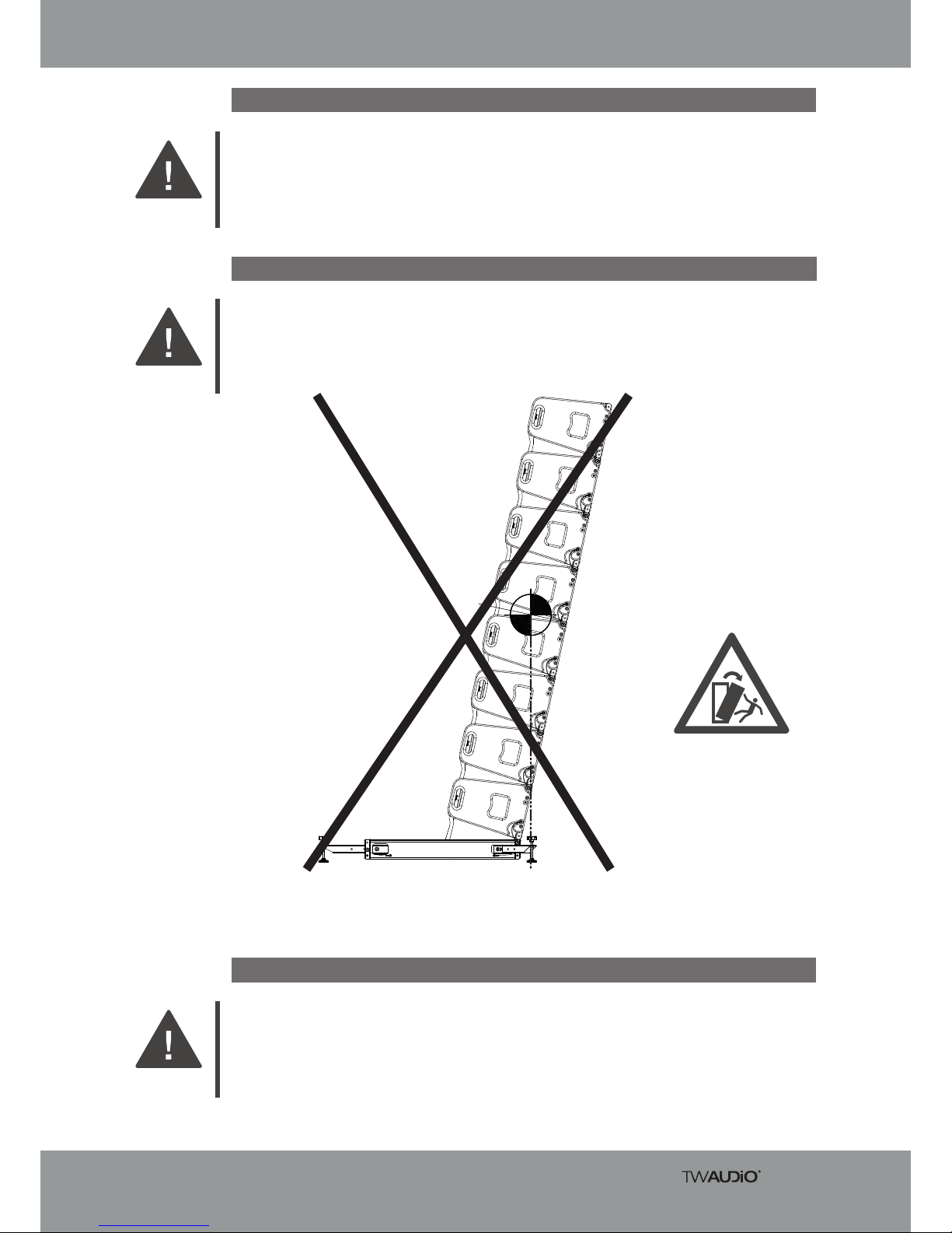
4.7 Pitfalls
Make sure that no one can trip over your system structures, or over individual components! This
is especially true for all pressure-resistant shims and spindle feet!
WARNING
For each downtilt system structure, make sure that the tipping point never exceeds the front
spindle feet!
Secure the entire downtilt system structure against tipping!
WARNING
Figure 4.8.1 - System structure – Danger of tipping
Before setting up the system outdoors, consider unforeseeable wind conditions at the operation
site!
In the event of imminent danger, dismantle your system structures immediately!
WARNING
4.8 Danger of tipping over
4.9 Windload
WARNUNG
Assembly Instructions VERA RF600
16
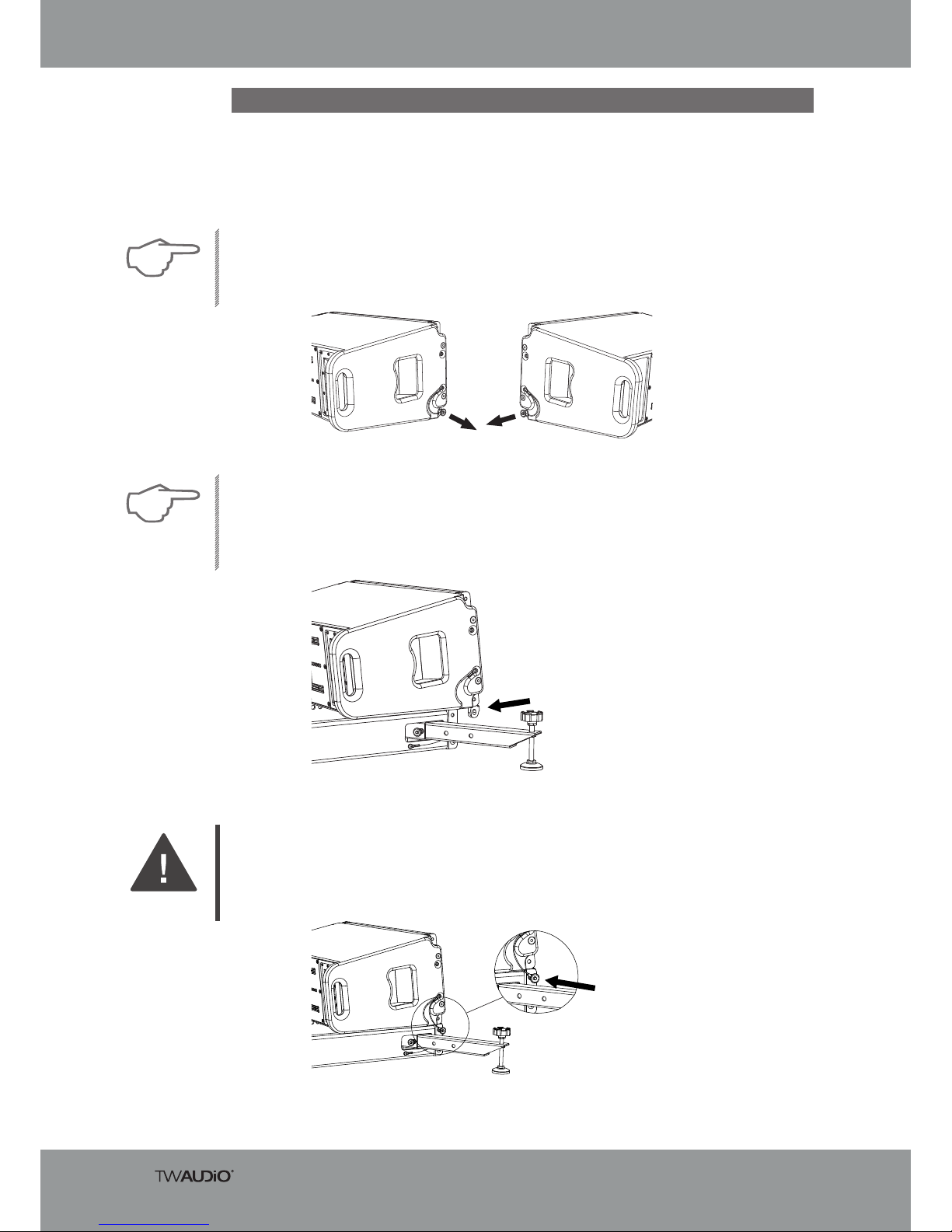
4.10 Groundstack of the lowest VERA20 speaker
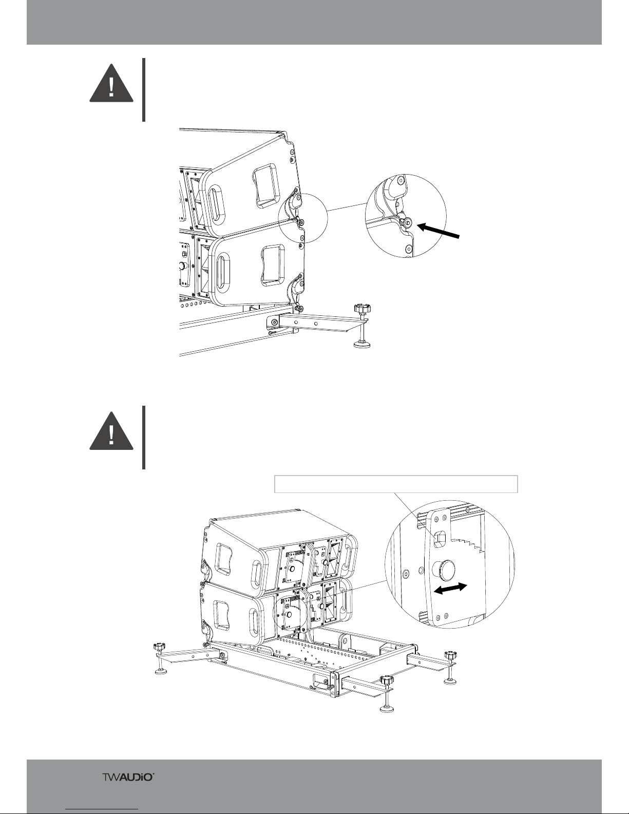
Figure 4.10.3 – Inserting the quick-lock pins
5. Insert the VERA20 loudspeaker’s two front quick-lock pins into the holes of the
VERA RF600 rigging frame.
WARNING
The fold-out hook on the rear rigging of the lowest VERA 20 loudspeaker is used to set the angle
of the assembly.
Follow these steps:
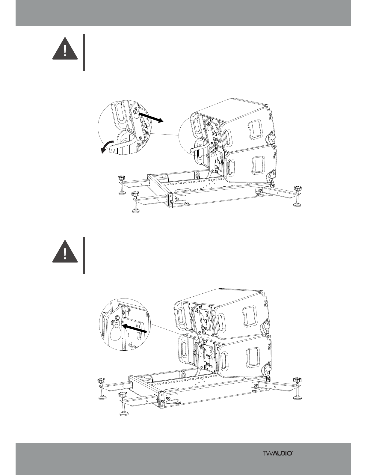
1. Loosen the two quick-lock pins at the front of the VERA20 speaker.
2. Both splay links in the front rigging rails must be extended downwards.
NOTE
Figure 4.10.1 - Loosening quick-lock pins on the VERA20
3. With the aid of a second person, place the VERA20 loudspeaker on the VERA RF600
rigging frame.
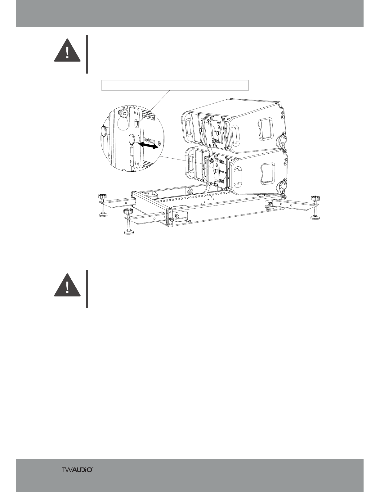
4. Pull back the VERA20 loudspeaker until its splay links align with the recesses of the
VERA RF600 rigging frame.
NOTE
Figure 4.10.2 – Pushing back the VERA20 speaker
Assembly Instructions VERA RF600
17
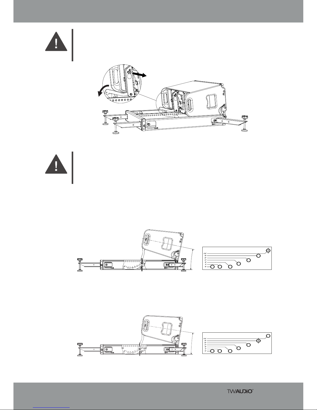
Figure 4.10.4 – Folding out the hook
6. Loosen the quick-lock pin on the main carrier of the VERA20 loudspeaker’s back
rigging and fold out the hook by 90°.
7. Lift the VERA20 speaker and pull the hook all the way down.
WARNING
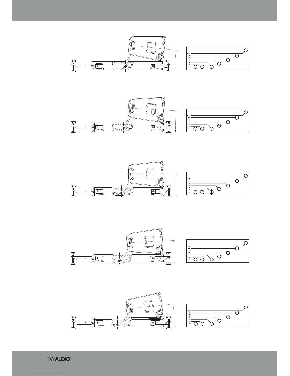
Variants:
Figure 4.10.5 – VERA20 loudspeaker side view – tilted down 12°
Figure 4.10.6 – VERA20 loudspeaker side view – tilted down 9°
8. Select the appropriate level (number of degrees) for your system setup.
See figures 4.10.5 to 4.10.11.
9. Attach the hook to the VERA RF600 rigging frame using the quick-lock pin on the
rigging frame.
WARNING
9°
1
2°
Assembly Instructions VERA RF600
18
Figure 4.10.8 – VERA20 loudspeaker side view – tilted down 3°
Figure 4.10.10 – VERA20 loudspeaker side view – tilted up 3°
Figure 4.10.11 – VERA20 loudspeaker side view – tilted up 6°
Figure 4.10.7 – VERA20 loudspeaker side view – tilted down 6°
Figure 4.10.9 – VERA20 loudspeaker side view at 0° (horizontal)
6°
3°
0
°
6
°
3
°

Assembly Instructions VERA RF600
19
4.11 VERA20 groundstack setup, from the 2nd speaker
Figure 4.11.1 - Loosening quick-lock pins on the VERA20
1. Please note that setting up the VERA RF600 rigging frame always requires two persons!
WARNING
Figure 4.11.2 – Pushing back the VERA20 speaker
To set up the ground stack array, starting from the second VERA20 loudspeaker, pro-ceed as
follows:
2. Loosen the two quick-lock pins at the front of the VERA20 speaker.
3. Both splay links in the front rigging rails must be extended downwards.
NOTE
4. With the aid of a second person, place the VERA20 loudspeaker on the first
VERA20 loudspeaker.
5. Pull back the VERA20 loudspeaker until its front splay links align with the rigging rails of
the lower loudspeaker.
NOTE
Assembly Instructions VERA RF600
20
Figure 4.11.3 – Inserting the quick-lock pins
6. Insert the VERA20 loudspeaker’s two front quick-lock pins into the holes of the
lower loudspeaker.
WARNING
Figure 4.11.4 – moving the left slider
7. Use the left slider on the lower VERA20 loudspeaker’s rear rigging to select the angle for
the next upper speaker.
WARNING
12° | 9,1° | 6,8° | 4,9° | 3,5° | 2,4° | 1,5° | 0,8° | 0,3° | 0°
Assembly Instructions VERA RF600
21
Figure 4.11.5 – Folding out the hook
8. Loosen the quick-lock pin on the main carrier of the upper VERA20 loudspeaker’s
back rigging and fold out the hook by 90°.
9. Lift the upper VERA20 loudspeaker unit at the back and pull the hook all the way down
so that it aligns with the rear rigging of the lower VERA20 loudspeaker unit.
WARNING
Figure 4.11.6 – Inserting the quick-lock pins
10. Insert the quick-lock pin into the main carrier of the lower VER20 loudspeaker’s rear
rigging to secure it.
11. Lower the VERA20 speaker until the hook comes to rest on the lower left slider.
WARNING
Assembly Instructions VERA RF600
22
Figure 4.11.7 – moving the right slider
12. Move the right slider of the lower speaker to the left until it displays the same number
of degrees as the left slider. This secures the upper loudspeaker.
WARNING
13. Follow the instructions in this section of the manual to connect additional VERA20 speakers.
WARNING
12° | 9,1° | 6,8° | 4,9° | 3,5° | 2,4° | 1,5° | 0,8° | 0,3° | 0°

Assembly Instructions VERA RF600
23
4.12 VERA S32 groundstack Setup
Figure 4.12.1 – VERA S32 loudspeaker on dolly
1. Please note that setting up the VERA RF600 rigging frame always requires two persons!
WARNING
Figure 4.12.2 – VERA S32 loudspeaker on dolly
2. Press down the locking levers on all castors with your foot. This will secure the dolly
from rolling away.
NOTE
3. With the aid of a second person, place the upper VERA S32 loudspeaker on the
back grill.
NOTE
Assembly Instructions VERA RF600
24
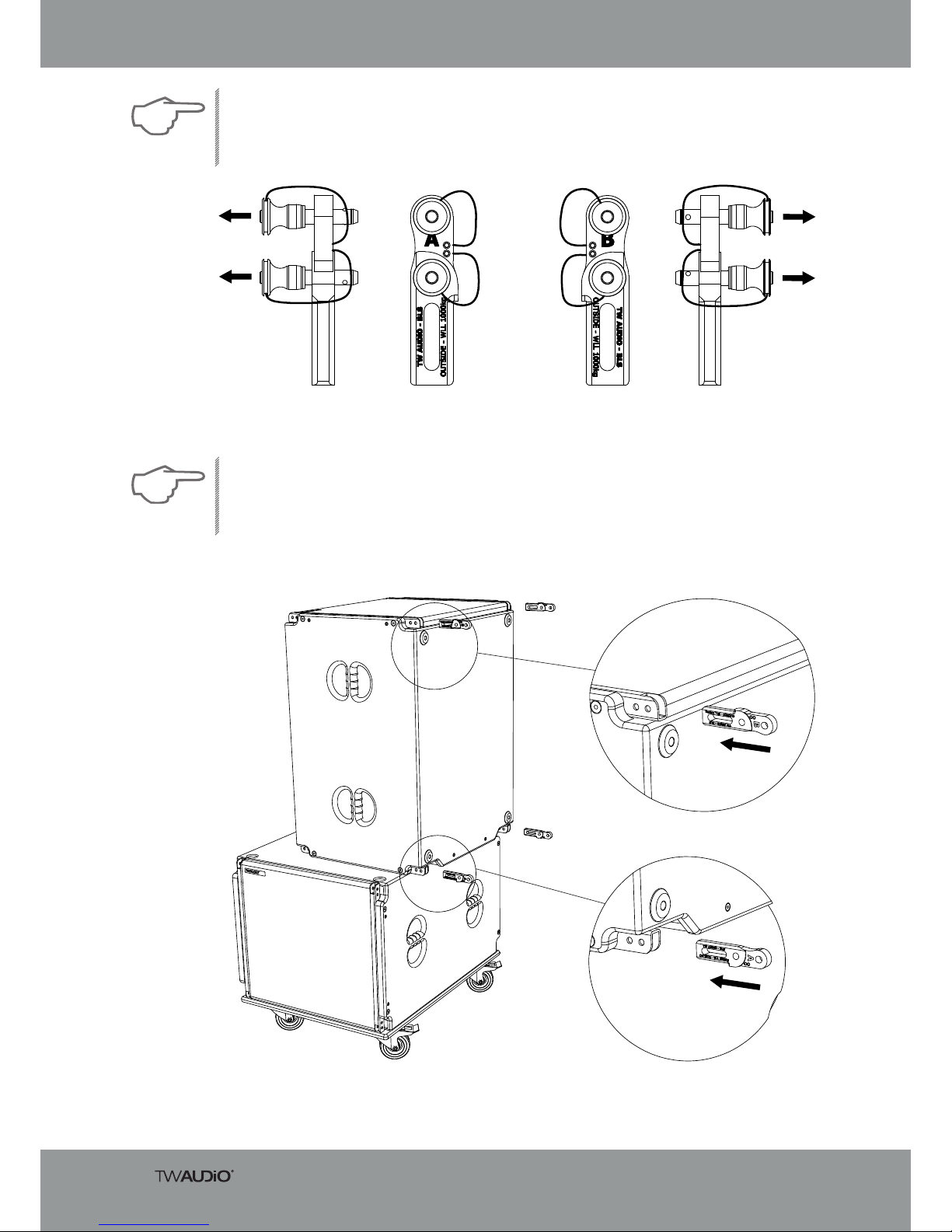
Figure 4.12.3 – BLS Box link set
Figure 4.12.4 – Inserting the box link connectors into the VERA S32 loudspeaker
4. Loosen all quick-lock pins on all four box link connectors of the BLS box link set.
NOTE
5. Insert all four box link connectors into the flying tracks of the VERA S32 loudspeaker.
6. Pay attention to the alignment of each box link connector. The “OUTSIDE” labels on all
box link connectors must be visible from outside.
NOTE
A
B
Assembly Instructions VERA RF600
25
Figure 4.12.5 – Inserting the quick-lock pins
7. Insert the lower quick-lock pin of each box link connector into the outer hole of the
VERA S32 loudspeaker’s flying track.
8. 8. Make sure that all quick-lock pins are always completely inserted!
WARNING
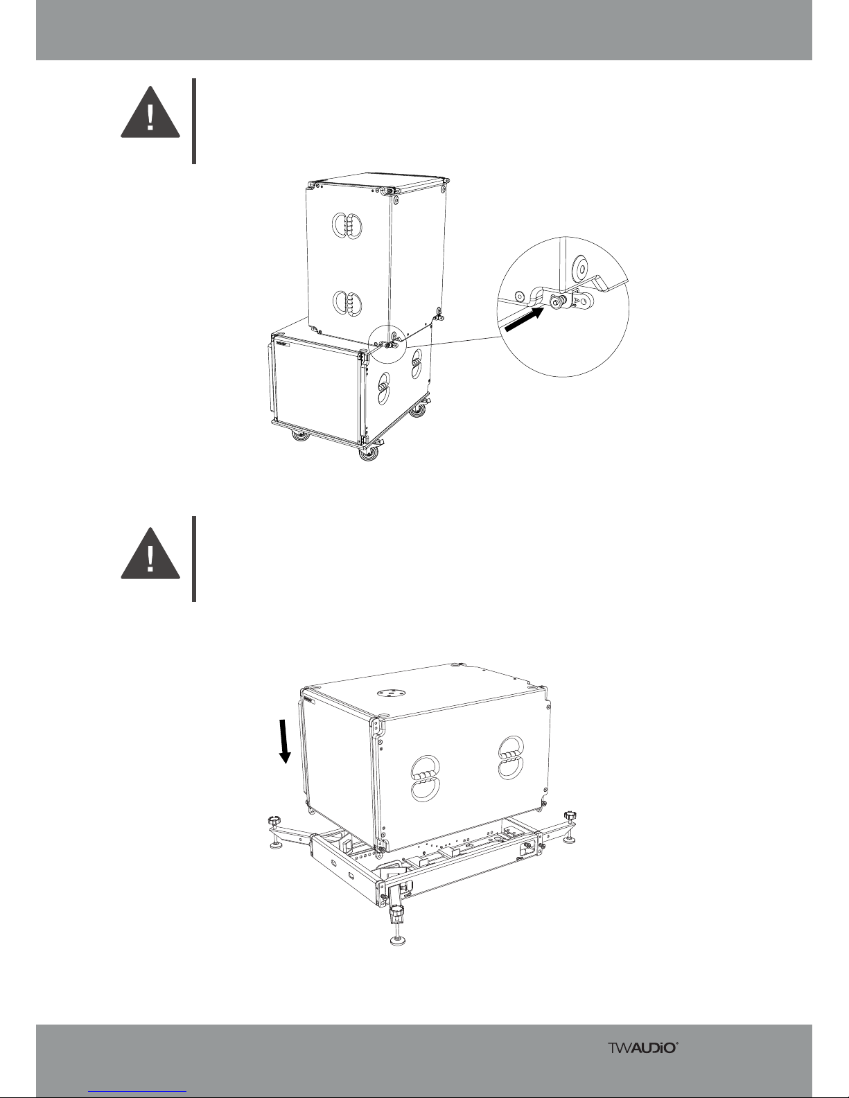
9. With the aid of a second person, lift the prepared VERA S32 loudspeaker onto the
prepared VERA RF600 rigging frame (see sections 4.2 to 4.6).
10. The box link connectors have to be inserted into the flying tracks of the rigging frame!
WARNING
Figure 4.12.6 – Positioning the VERA S32 loudspeaker on the VERA RF600 rigging
frame
Assembly Instructions VERA RF600
26
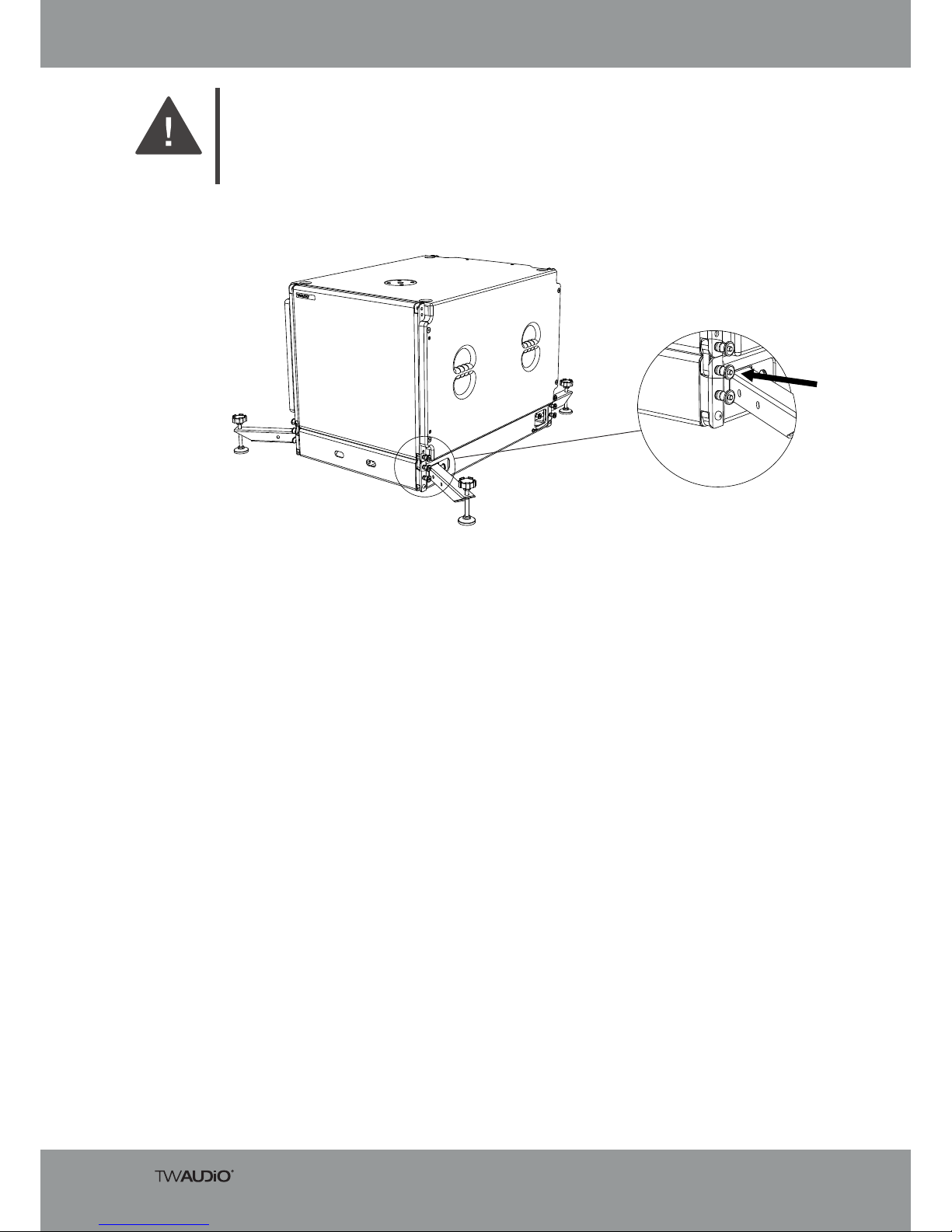
Figure 4.12.7 – Inserting the quick-lock pins
11. Insert the second quick-lock pin of each box link connector into the upper hole of the
VERA RF600 rigging frame’s flying track.
12. Make sure that all quick-lock pins are always completely inserted!
WARNING
Assembly Instructions VERA RF600
27
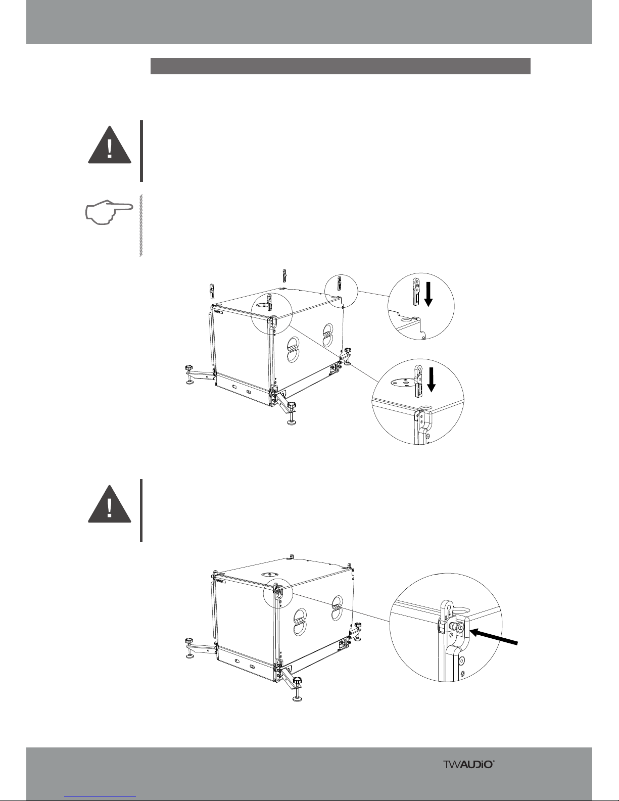
4.13 VERA S32 ground stack setup, from the 2nd speaker
Figure 4.13.1 – Inserting the box link connectors into the VERA S32 loudspeaker
(top)
1. Please note that setting up the VERA RF600 rigging frame always requires two persons!
WARNING
Figure 4.13.2 – Inserting the quick-lock pins
To set up the ground stack array, starting from the second VERA S32 loudspeaker, pro-ceed
as follows:
2. Insert all four box link connectors from the box link set into the flying tracks of the
VERA S32 loudspeaker.
3. Pay attention to the alignment of each box link connector. The “OUTSIDE” labels on all
box link connectors must be visible from outside.
NOTE
4. Insert the lower quick-lock pin of each box link connector into the upper holes of the
VERA S32 loudspeaker’s flying track.
5. Make sure that all quick-lock pins are always completely inserted!
WARNING
A
B
Assembly Instructions VERA RF600
28
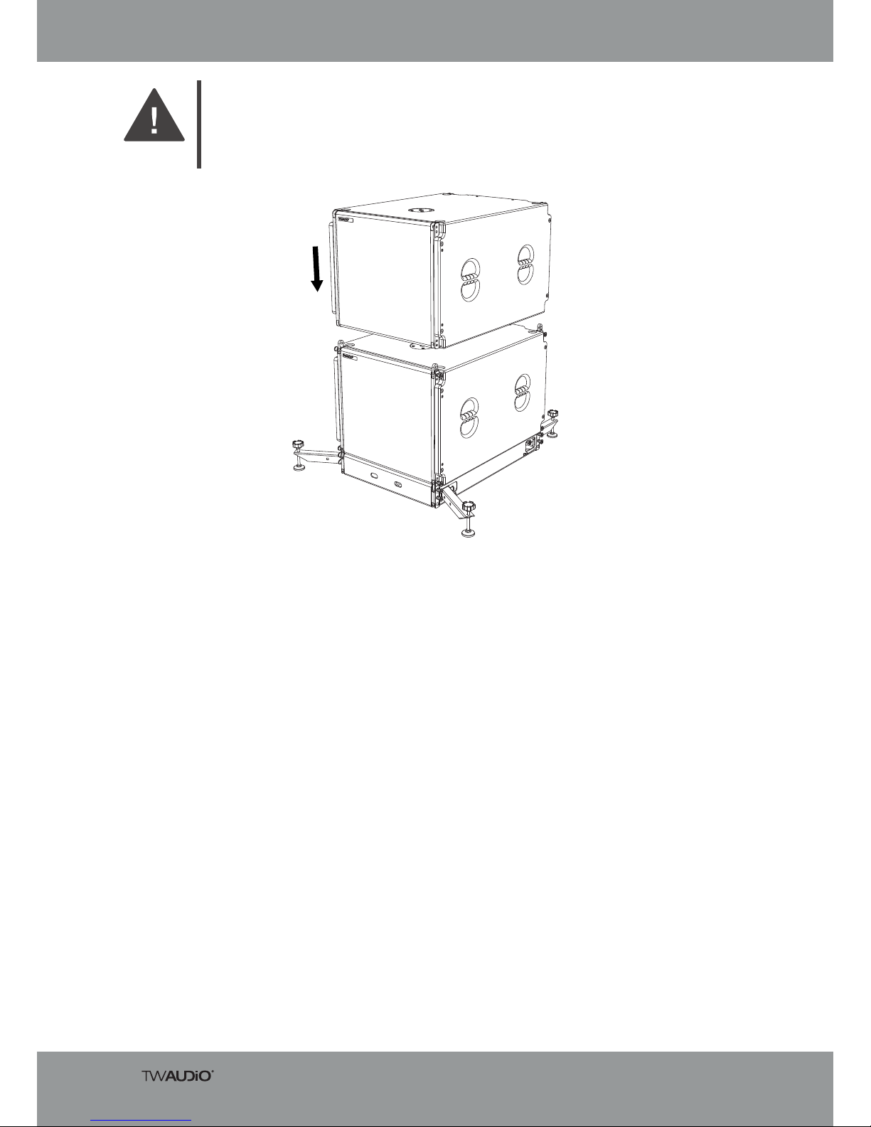
Figure 4.13.3 – Second VERA S32 speaker on top of first speaker
6. With the aid of a second person, place the second VERA S32 loudspeaker on the
first loudspeaker.
7. The box link connectors have to be inserted into the flying tracks of the lower loudspeaker!
WARNING
 Loading...