

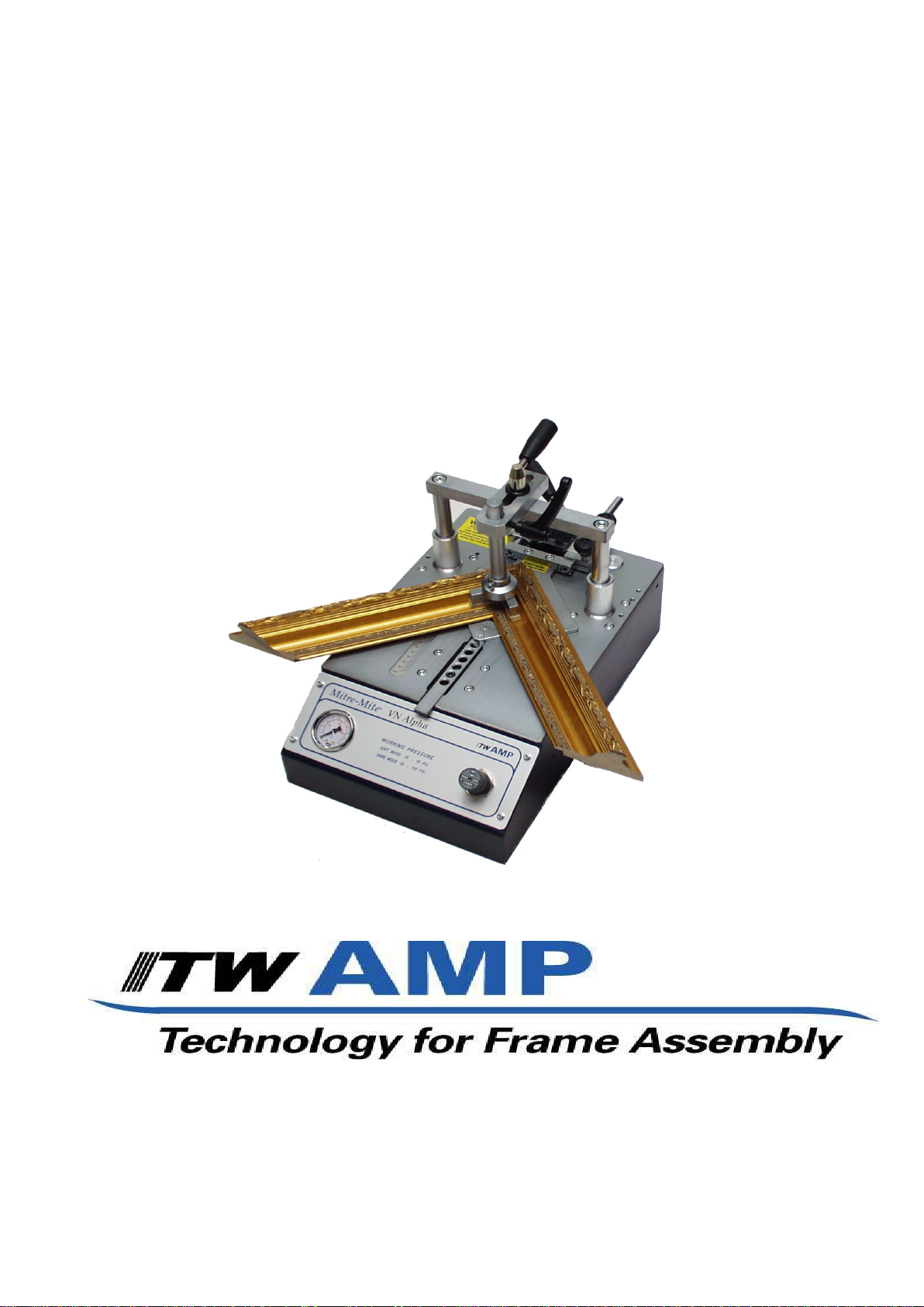
®
Mitre-Mite
VN Alpha
Instruction Manual
Version E
100 Fairway Drive Suite 114 Vernon Hills, IL 60061
Phone: 1-800-322-4204
Fax: 1-800-426-7019
1

Index
1. GENERAL INFORMATION 3
1.1 PRODUCER 3
1.2 ASSIST ANCE CENTERS 3
1.3 CERTIFICA TION 3
1.4 WARRANTY 3
1.5 PRE-ARRANGEMENTS CHARGED TO THE
CUSTOMER 3
1.6 HANDBOOK STRUCTURE 3
1.6.1 Object and contents 3
1.6.2 Users 3
1.6.3 Preservation 3
1.6.4 Symbols utilized 4
2. MACHINE DESCRIPTION 5
2.1 WORKING PRINCIPLE 5
2.2 MAIN COMPONENTS 5
2.3 MACHINE STRUCTURE 5
2.4 DIMENSIONS 5
2.5 SURROUNDING CONDITIONS 5
2.6 LIGHTING 5
2.7 VIBRATIONS 5
2.8 NOISE EMISSIONS 5
2.9 TECHNICAL DATA 6
2.10 STANDARD EQUIPMENT 6
2.10.1 Standard accessories 6
2.10.2 Upgrading and implementing of mechanical parts 6
2.10.3 Optional accessories 6
2.10.4 Customized optional accessories 6
2.1 1 ELECTROMAGNETIC AMBIENT 6
4.7.2 V-nail
(R)
clawhead replacement to change V-nails size10
4.8 ADJUSTMENTS 11
4.8.1 V-nails
4.8.2 Vertical clamp adjustment 12
4.8.2a Vertical clamp position adjustment 12
4.8.2b Vertical clamp height adjustment 12
4.8.3 Frontal clamp adjustment 12
4.8.4 Working pressure adjustment 13
4.8.5 Protective shield adjustment 14
(R)
inserting positions adjustment 11
4.9 CHECKING OPERATIONS TO BE EFFECTED
BEFORE WORKING ST ART 14
5. FUNCTIONING 15
5.1 OPERATORS 15
5.2 FUNCTIONING DESCRIPTION 15
5.3 TIPS FOR PERFECT JUNCTIONS 15
5.4 MACHINE STOP 16
5.5 MACHINE REINSTA TEMENT 16
5.6 PUTTING OUT OF SERVICE 16
6. MAINTENANCE 16
6.1 STATE OF MAINTENANCE 16
6.2 MACHINE ISOLATION 16
6.3 SPECIAL CAUTIONS 16
6.4 CLEANING 16
6.5 LUBRICATION 17
6.6 ORDINARY MAINTENANCE 17
6.7 EXTRAORDINARY MAINTENANCE 17
7. DIAGNOSTIC 18
7.1 SAFETY WARNINGS 18
7.2 TROUBLESHOOTING 18
7.3 REQUEST OF ASSIST ANCE 19
8. SPARE PARTS 20
3. SAFETY 7
3.1 GENERAL W ARNINGS 7
3.2 SCHEDULED USE 7
3.3 INADVISABLE USE 7
3.4 DANGEROUS AREAS 7
3.5 PROTECTION DEVICES 7
3.6 STOP FUNCTIONS 7
3.7 SAFE WORKING PROCEDURES 7
3.8 RESIDUAL RISKS 8
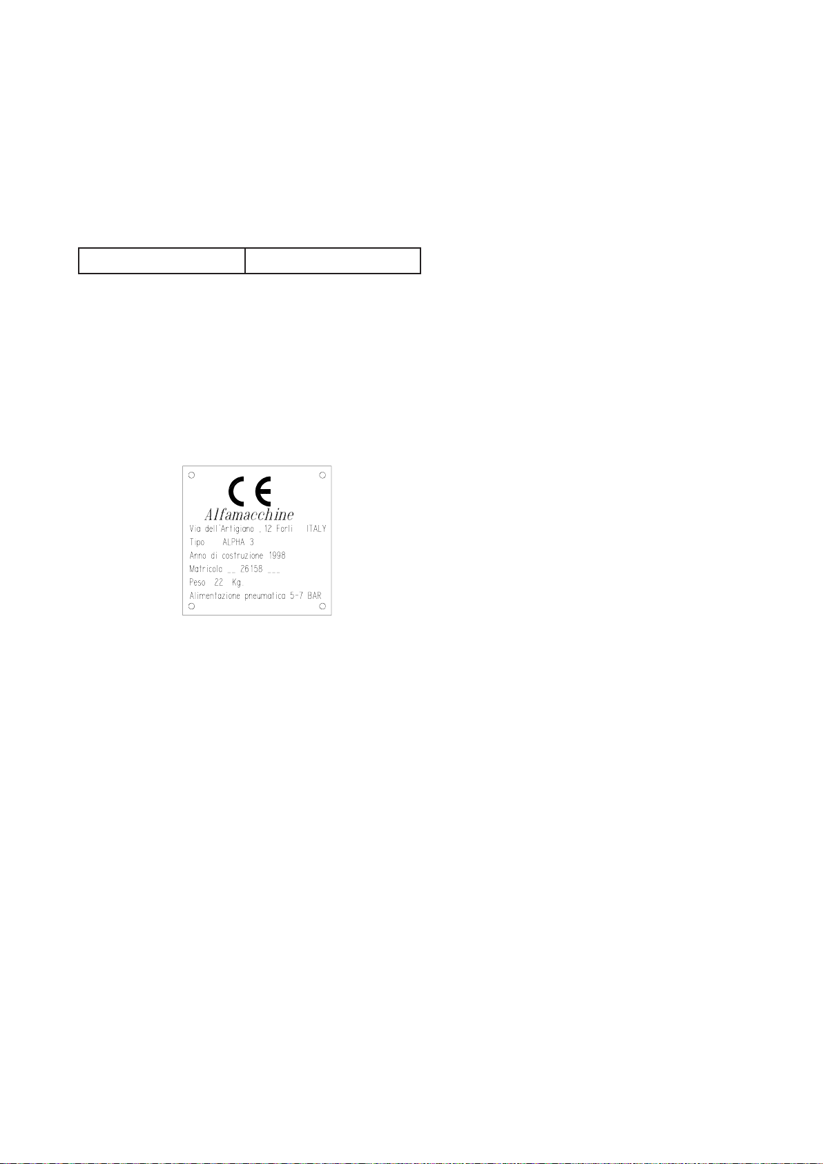
3.9 PLATES 8
4. INSTALLATION 8
4.1 SHIPPING AND HANDLING 8
4.2 STORAGE 8
4.3 PRELIMINARY ARRANGEMENTS 9
4.4 UNPACKING 9
4.5 CONNECTIONS 9
4.5.1 Pneumatic connection 9
4.6 PRELIMINARY CONTROLS 10
4.7 MACHINE ARRANGEMENT 10
4.7.1 V-Nails
2
(R)
magazine loading 10
8.1 SPARE PARTS LIST 20
8.2 SPARE PARTS ORDERING 20
9 DEMOLITION 20
9.1 DEMOLITION 20
10. ATTACHMENTS 20
10.1 DECLARA TIONS 20
10.2 SCHEMES 20
1. GENERAL INFORMATION
1.1 PRODUCER
The firm Alfamacchine-ITW/AMP can boast more than 10
years of experience in the construction of Woodworking
Machines. It has acquired the technological know-how,
developed during years of research in strict touch with
manufacturing departments and international
commercialization. We offer the best warranty that anyone
can grant its customers.
TEL 1-800-322-4204 FAX 1- 800-426-7019
1.2 ASSISTANCE CENTERS
ITW/AMP is represented in North and South America by a
numerous and prepared sales organization. Contact our firm
directly to get the name of your local distributor.
For every need regarding Use, Maintenance or Request of
Spare Parts, the Customer should call the local authorized
service center or directly to ITW/AMP, specifying the
machine identification data impressed on the plate.
The warranty is also void in case you use V-nails
from the original ITW/AMP ones.
To take advantage of warranty services is necessar y, at the
moment you receive your machine, to fill out the war ranty
card and send it back as soon as possible to ITW/AMP.
The warranty will be valid only after ITW/AMP receives the
warranty card & records it.
(R)
different
1.5 PRE-ARRANGEMENTS CHARGED TO THE CUSTOMER
It is the customer’s duty , on times agreed with the producer ,
to execute what is indicated in our documentation.
Things normally charged to the customer are:
• Premises predisposition, included building works and/
or canalization eventually requested
• Pneumatic supplyng of compressed air (see the
paragraph 4.5)
1.6 HANDBOOK STRUCTURE
The customer must pay extreme attention to the indications
reported on this handbook. The proper Pre-Arrangement,
Installation and Use of the Machine, constitute the basis of
a correct customer-manufacturer relationship.
1.3 CERTIFICATION
The machine is produced in conformity to the pertinent
European Community Norms in force at the moment of its
introduction on the market.
1.4 WARRANTY
The ITW/AMP’s products are constructed to have a long life
and are tested one by one.
If, in spite of this, if any damages or malfunctioning would
occur, the replacement of defective parts is warranted
(counting from the date written on the delivery bill) for a
period of:
- 24 months for mechanical components
- 12 months for pneumatic part
The driver blade is tested for about 1.000.000 w orking cycles.
The W arranty does not include the sending of technical staff.
The repair interventions will be performed at your local
distributor or ITW/AMP’s plants. The shipping costs will be
entirely charged to the Customer.
The warranty does not cover the damages due to an
inappropriate use of the machine or not corresponding to
the instructions described in this handbook.
Warranty decays in case of unauthorized modifications or
because of accidental damages or tampering performed by
unqualif ied personnel.
1.6.1 Object and contents
This goal of this handbook is to provide to the customer all
the necessary information so that they can properly use the
machine & be able to run it in complete autonomy and safety .
The handbook contains information concerning the
technical aspects, machine working and standstill,
maintenance, spare parts and safety. Before making any
operation on the machine, the qualified technicians and
operators must read carefully this handbook. In case of doubt
about the correct interpretation of these instructions, ask
ITW/AMP or your local distributor to have the problem
explained.
1.6.2 Users
This handbook is made for the operators and technicians
authorized to perform the machine maintenance.
The operators can not execute operations reserved to the
maintaince staff or the qualified technicians.
The producer does not answer to damages derived from notobserving this prohibition.
1.6.3 Preservation
The instruction handbook must be kept very closed to the
machine, into a special container protected from liquids and
whatever could compromise its legibility
3
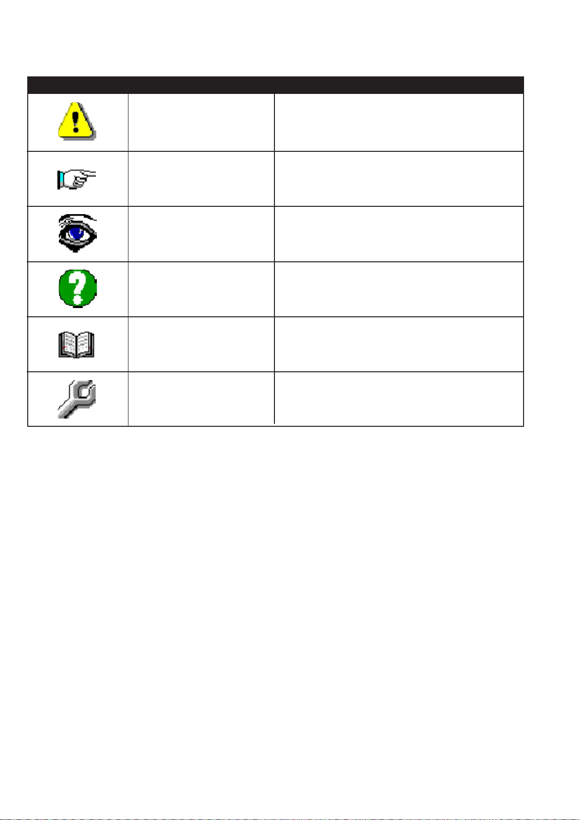
1.6.4 Symbols utilized
P...
A...
O...
I...
C...
DANGER
WARNING
OBSERVATION
INQUIRY
EXAMINATION
ADJUSTMENT
It indicates a danger with a mortal risk for the operator
It indicates a warning or a note about key functions or useful
information. Pay the maximum attention to the paragraph
marked with this symbol.
It is requested to take a measurement data, to check a
signal,....
The user is requested to check the proper positioning of any
element of the machine, before operating a certain command
It’s necessary to consult the handbook before performing a
certain operation
In case of a strange sitituation and/or anomalies, you can be
requested to perform a certain mechanical adjustment.
R...
4
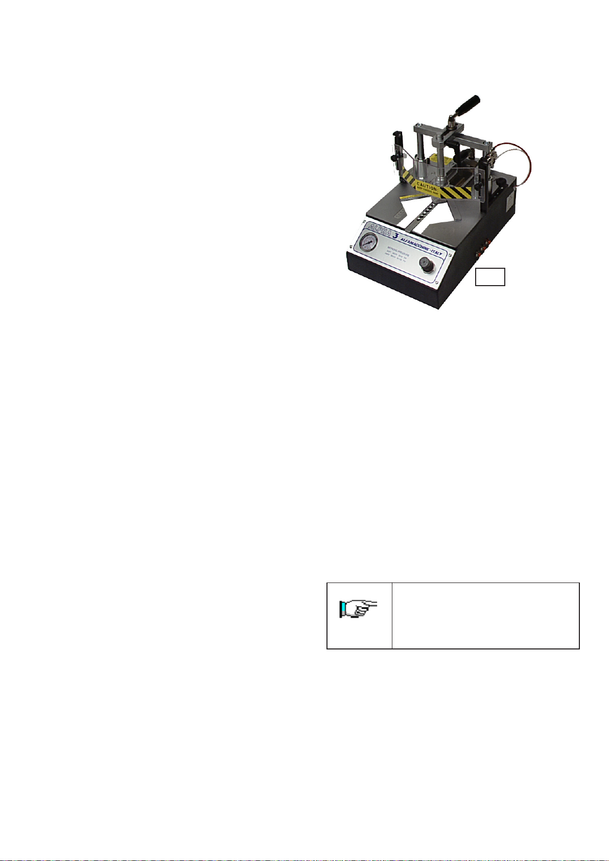
2. MACHINE DESCRIPTION
2.1 WORKING PRINCIPLE
The benchtop Frame Assembling Machine Mitre Mite VN
Alpha has been manufactured to assemble any kind of frame.
The Mitre Mite VN Alpha , being of simple construction and
extremely easy to use, makes it possible to join with absolute
precision any kind of moulding by means of special steel V-
(R)
nails
.
It uses V-Nails
(R)
with the “pulling pow er” effect in dif ferent
sizes.
2.2 MAIN COMPONENTS
The main components constituting the machine are:
- Pneumatic clamping device to allow a proper locking
of the mouldings to insert several V-nails
(R)
in different
positions
- Magnetic pressure pads of several types, at quick
replacement, to have the proper clamping of an y profile
- Dual functions foot operating pedal for separate control
of clamping and nail insertion
- Pneumatic opening of the V-nail
(R)
magazine for a very
quick reloading
- Nail heads sizes 7, 10 and 15 mm.
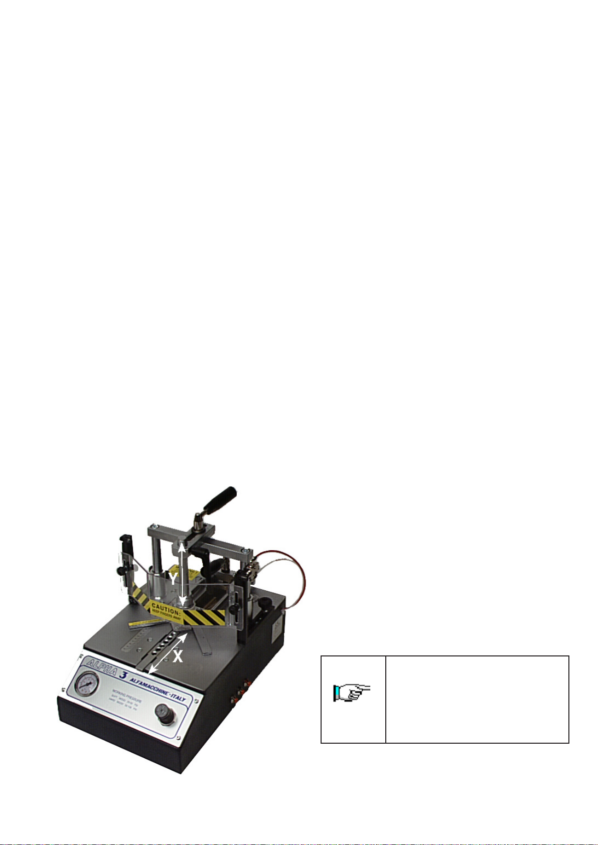
2.3 MACHINE STRUCTURE
The movement directions during the machine working are
the followings:
- X AXIS
Movement of horizontal clamp
- Y AXIS
Movement of vertical clamp
2.4 DIMENSIONS
The overall dimensions are reported on table 2.9-A
2.5 SURROUNDING CONDITIONS
The machine does not need special surrounding conditions.
It has to be installed inside an industrial building, lit, aired
and with a compact and flat floor. The permitted temperatures
go from 41° to 104° F, with a humidity level not higher than
50% at 104° F or 90% at 68° F.
2.6 LIGHTING
Premises lighting must be conformed to the norms in force
in that Country where the machine is installed and has to
guarantee a clear visibility and can not create dangerous
light reflections.
2.7 VIBRATIONS
In standard conditions conformed to the indication of
machine proper utilization the vibrations do not create
dangerous conditions. The a verage quadratic weighed level,
according to the acceleration frequency to which arms are
exposed does not exceed 2,5 m/s2.
2.8 NOISE EMISSIONS
The machine is designed and projected for reducing the noise
emission level to its source. In standard working conditions
the Machine noise power level is:
Acoustic Continuous Equivalent weighed
pression A <70dB
Acoustic Istantaneous weighed
pression <130dB
The noise levels indicated are emission levels and are not
representative of operating levels. In spite of existing a
relationship between emission levels and exposure ones,
this can not be used in a reliable way to def ine if further
precautions are necessary. The factors determining the
exposure level to which the working force is subjected,
include exposure length, working premises characteristics
and other noise sources (number of machines, closed
building, etc…). Furthermore the allowed exposure levels
could change according to the several Countries. At any
rate, the information provided, will allow the Machine
Operator to achieve a better understanding of the dangers
and risks they are submitted to.
The indicated noise levels are emission
ones measured in standard conditions of
use. In case of any machine modification,
the above mentioned levels could be
changed and should be tested on the same
machine.
5

2.9 TECHNICAL DATA
We have listed below the Machine’s data and technical
characteristics to which make reference for any eventual
contact with your distributor for Technical Assistance.
TABLE 2. 9 A
Frames thickness min.-max. .24”- 3.15”
Frames width min.-max. .24”- 2.76”
V-nails magazine capacity n. 220
V-nails size mm 7-10-15
V-nails size on request mm 3-5-12
Pneumatic Supplying 40-100 PSI
Weight about 62 LB
Height of working bench 5.1”
Overall dimensions 17.1”x13”x11.8”
2.10 STANDARD EQUIPMENT
The equipment listed below is standard.
2.10.1Standard accessories
Once you have removed the packaging, please check the
presence of the following accessories:).
- N.1 nail head mm. 7
- N.1 nail head mm.10
- N.1 nail head mm.15
- N.1 L shaped pressure pad
- N.1 Rounding pressure pad
- N.1 Allen Wrench 5 mm. for V-nails head replacement
- N.1 Brass rod magnet to remove V-nails
Picture 1
Picture 2
2.10.2Upgrading and implementing of mechanical parts
This machine has been manufactured following a modular
criteria, therefore the existing equipment can be further
upgraded with additional accessories that will not alter its
basic structure.
Technical upgrades on the machine model, if any, will be
such that they can be installed at any time without requiring
any substantial modifications to the machine structure.
2.10.3Optional accessories
• Soft clamping of the moulding that allows to clamp the
moulding at low pressure
• Floor stand
• Adjustable tilting fences (see fig. 3)
• Wooden working bench extension
• Metallic working bench extension
• Special fences for octagons (fig.1)
• Special fences for hexagons (fig.2)
• Round and square pressure pads in rubber
• V -nails claw heads size 3-5-12 mm.
Picture 3
2.10.4Customized optional accessories
Thanks to its versatility this machine can be ‘custom-made’
to meet our users requirements. Additional accessories can
be made by your local machine shop, that can make the
frame assembling easier: EX: special fences for peculiar
moulding shapes, special clamps to ensure the mouldings
are locked properly during V-nail firing, and so on.
2.11 ELECTROMAGNETIC AMBIENT
The Machine is designed to operate properly in an industrial
electromagnetic ambient without altering it being an
exclusively pneumatic machine.
6
3. SAFETY
3.1 GENERAL W ARNINGS
The operator must pay the maximum attention to the
information written in this Handbook, expressively about
proper precautions for Safety listed in this chapter.
It is imperative for the operator to follo w the warnings listed
below:
• Keep the machine and the working clean & ordered
• Provide appropriate containers to stock the pieces you
will be working with
• Use the Machine only in a normal psycho-physical
conditions
• Wear adequate clothing to avoid obstacles and/or
dangerous entanglements to/from the machine
• Wear the individual protection gears prescribed by the
instruction handbook, regarding the effected operations
• Do not remove or alter the warning plates and adhesive
signs
• Do not remove or elude the Machine Safety Systems
• Keep the fingers away from the working area
• Disconnect the air pressure supply during any
maintenance intervention
• Keep your foot off of the pedal during machine
maintenance
3.2 SCHEDULED USE
The Machine is designed and built to assemble mitred
corners.
The machine is projected for manual use only (under
operator’s control).
Figure 3.4.A- Working area and dangerous zones
Dangerous zone
3.5 PROTECTION DEVICES
The machine is equipped with adequate protections for
persons exposed to the risks due to the transmission mobile
elements,taking part in working (driver blade, horizontal
clamp, vertical clamp).
3.6 STOP FUNCTIONS
The machine stop functions are the following:
• Fast clutch fitting stop (Category 0).
• Foot pedal Stop (Category 1).
3.3 INADVISABLE USE
The machine can not be used:
• For uses different from those listed in paragraph 3.2
• In an explosive or aggressive atmosphere, where there
is a high density of dust or oily substances suspended
in the air
• In a flammable atmosphere
• Outside in all weather severity
• For working materials not suitable with the machine’s
characteristics
3.4 DANGEROUS AREAS
The area where the frames are assembled is defined as the
“working area”
The dangerous areas of the machine, include the movable
parts and the surrounding zones
STOP CATEGORY 0
It is obtained by disconnecting the fast clutch fitting from
the air feed system (uncontrolled stop).
STOP CATEGORY 1
Controlled stop is obtained by lifting the foot from the
pneumatic pedal, which does not allow the v-nails
or the clamps to work.
(R)
to fire
3.7 SAFE WORKING PROCEDURES
The machine is projected and realized to
eliminate any risk connected with its use.
The user is requested to achieve an adequate
training to be instructed by your local
distributor or ITW/AMP’s technicians.
The other risks related with using the machine are:
- Finger crushing in the vertical clamp working area
- Finger crushing in the frontal clamp working area
It is necessary to carefully follow the follo wing instructions:
1 Keep the fingers away from frontal and vertical clamp
working areas
2 Disconnect the air pressure during any maintenance
interventions
3 Keep the foot away from the pedal during machine
maintenance
7

3.8 RESIDUAL RISKS
During the normal working cycle and while performing
maintenance, the operators are exposed to several residual
risks that, because of operations own nature, can not be
totally eliminated.
• Risk of f inger crushing in the working areas of the
vertical and frontal clamps
3.9 PLATES
The warning plates carrying out safety functions & can not
be removed, covered or damaged.
To see the location of the plates or adhesive signs , see
Fig.10.2-D
Ta ble 3.8 A- Types of plates
4. INSTALLATION
4.1 SHIPPING AND HANDLING
The shipment must be performed by a professionally
qualified staff. The machine has to be shipped in a safe way
to avoid any damage to its parts.
• All the protections and guard devices must be properly
closed and locked.
• The machine has to be shipped like positioned for
installation.
• Before the shipment, it is necessary to lubricate the parts
which are not painted
• According to the type of shipment, it is necessary to
protect the machine from any jarring impact or stress
Figure 4.1A – machine handling indications
Plate concerning machine characteristics
Adhesive sign concerning the finger danger zone
Adhesive sign concerning the behaviour to be kept during
the working cycle
Adhesive sign concerning the behaviour to be kept during
the working cycle
Machine total weight: about 62 LB
The machine lifting must be performed by 2
operators.
Any damaging of the machine caused during its shipment
or handling is not covered under wa r ranty.
Repairs or replacements of damaged parts are charged to the
customer.
4.2 STORAGE
In case of long inactivity, the machine must be stored with
precautions concerning storage place and times.
• Store the machine indoors
• Protect the machine from jarring impacts and stresses
• Protect the machine from humidity and high
temperatures
• Avoid corrosiv e materials that could touch the machine
• Lubricate the parts which are not painted
8

4.3 PRELIMINARY ARRANGEMENTS
In order to install the machine it is necessary to prepare a
working area adequate to the machines dimension & the
length of moulding you will be working with.
T o fulfill the characteristics of precision and steadiness, the
bench frame assembling machines must be positioned on a
solid and leveled plane able to sustain the weight of the
machine. The bench must be studied and prepared by the
customer and/or qualified staff.
4.4 UNPACKING
The benchtop machine is shipped packed into an
appropriate carton and protected by polystyrene parts.
Remove the external packing and save it for a future use.
Check for any casual shipping damage and report it
immediately to the carrier. Shipping damages or any other
defects must be reported to ITW AMP or your local
distributor, within 3 days from receipt of the machine.
4.5 CONNECTIONS
To avoid any problems while setting up your machine, it is
recommended that you follow the instructions below.
Picture 5
Use the supplied fast clutch fitting to connect the air
compressor system. You could use also another f itting
suitable with your pneumatic system (see fig. 6).
4.5.1 Pneumatic connection
The machine is controlled by a dual action footpedal.
The 3 pipes the pedal must inserted into the 3 fittings located
on machine’s right side in the following sequence (fi. 4-5):
Upper connection Red pipe into the red fitting
(external side)
Central connection Black pipe into the black fitting
(central fitting)
Low er connection Transparent pipe into the 3rd fitting
(user side)
Picture 6
We recommend that you install a f ilter/
lubricator on the compressed air system to
obtain clean and lubricated air.
Use only silicone lubricating oil for
pneumatic systems. The use of inadequate
oil could damage the valves.
Once you have connected the machine with the pneumatic
system, check the proper operation of the foot pedal in the
following way: Move the vertical bar to its full up position
(see paragraph 4.8.2b).
• Pressing the footpedal half way down activates the
horizontal clamp, vertical clamp and the fence locking
• The foot pedal pressed full down activates the V-nail
driver
(R)
Picture 4
Check the foot pedal operating when the
(R)
V-nail
magazine is closed. The foot
pedal control is deactivated when the V-
9

4.6 PRELIMINARY CONTROLS
The Machine preliminary operations before starting the
machine, must be executed by a technician appointed by
the customer. Before setting up the machine, it is necessary
to execute certain verifications and checks to prevent
mistakes or accidents during setup.
• Verify that the machine has not been damaged during
the assembly steps.
• Verify with extreme care, the pipes integrity
4.7 MACHINE ARRANGEMENT
4.7.1 V-Nails
To load the V-nails
• Move the clawpusher backwards by pulling backwards
on the control wire (see fig. 7).
• Insert one or more V-nail
sharpened edge of the V-nails
that they are loaded with the V of the nails pointing in
the direction indicated in the figures 8 and 9. Make sure
that you hav e the correct type of cla w head for the nails
that you are using.
• Move the claw pusher forward by gently releasing the
control wire (see fig.7)
(R)
magazine loading
(R)
magazine proceed as follows:
(R)
strips, making sure that the
(R)
(glue side) faces up and
Picture 7
Picture 8
Picture 9
4.7.2 V-nail
The V -nail
V-nails
(R)
clawhead replacement to change V-
(R)
nail
size
(R)
guide head must be changed each time you use
(R)
of different sizes.
Proceed as follows to replace it:
• Loosen the locking screw of the V-nail
(R)
guide head
using the proper 5 mm Allen wrench (the screw is on the
opposite side from the V-nail
• Remove the V-nail
(R)
guide head
(R)
magazine(See fig. 10)
• Move the clawpusher backwards by pulling backwards
on the control wire. This will permit access to the V-
(R)
nail
magazine (see fig. 8).
• Remove all the V-nails
(R)
that are still in the magazine
(using the proper brass magnet, if necessary) (see fig.11).
• Insert the new V-nail
(R)
stick(of desired height) into the
magazine
• Move the clawpusher forward by geltly releasing the
control wire. (see figure 7).
• Inser t the new size V-nail guide head to match the Vnails to be used (see fig. 12).
• Tighten the locking screw of the V-nail guide head (see
fig.10).
10

Picture 10
4.8 ADJUSTMENTS
The machine has been completely tested & checked in ITW/
AMP’s plants before its shipment. All the operator has to do
is perform the following adjustments:
4.8.1 V-nail
To properly position the mouldings to be assembled, the
Mitre Mite VN Alpha is equipped with a 90° fence.
The fence can be shifted forward or backward in order to
allow the proper positioning of the v-nails
moulding.
The fence stops (backward and forward) can be set with
precision by means of locking clamps. (see fig. 13).
The operator can easily use the machine to insert V-nails
with extreme precision into 2 different positions (fig. 14).
(R)
inserting positions adjustment
(R)
in the
Picture 11
Picture 12
Picture 13
Picture 14
11

4.8.2 Vertical clamp adjustment
The vertical clamp can be adjusted in height and position.
Proceed as follows to adjust them:
4.8.2aVertical clamp position adjustment
• Position the mouldings to be assembled on the working
bench
• Select the pressure pad suitable with the profile of the
moulding to be assembled and put it on the vertical bar
• Loosen the handle (see f ig.15) that locks the clamp,
which holds the vertical bar. This will permit its
movement forwards or backwards. You will need to
position the pressure pad directly over where the v-
(R)
nails
will be inserted.
• Tighten the handle once you have reached the proper
position
B
Picture 16
4.8.3 Frontal clamp adjustment
The Frontal Clamp (horizontal clamp) has a series of holes
in the flat bar (see fig.17).
Lift the bar upwards to take it out of its initial position. You
will now be able to move it forwards and backwards.
T o lock the bar it is suf ficient to insert it into the proper peg
located in the middle of the guide channel.
Picture 15
4.8.2bVertical clamp height adjustment
• Loosen the side handle (see f ig. 16) and adjust the
pressure pad height over the frame. It is recommended
that you set the height between 5 and 8 mm above the
moulding. This will help to a void an y accidental fingers
crushing.
• Tighten the handle once you have reached the proper
position.
• Lower the vertical clamp by pressing half w ay down on
the foot pedal. This will v erify that the mouldings to be
assembled are properly clamped.
• Press all the way down on the foot pedal to insert the V-
(R)
nail
.
Proceed as follows to position the frontal Clamp correctly:
1. Remove the bar from the peg by lifting it upwards by
about 10-15 mm. Move it forward until it touches the
moulding to be assembled (see fig.18).
2. Lower the bar into the next available hole & over the
peg.
Picture 17
12

DO NOT ADJUST the pressure
if the machine is not connected
to the air supply.
The suggested pressures are:
Soft woods (samba,........) 30-40 PSI
Medium (ramin,........) 40-60 PSI
Very hard woods (oak) 60-80 PSI
Picture 18
In case of continued use without needing
to remove the frontal clamp from its
position, it is possible to fix it into the peg
using the proper screw.
When shipping the machine, it is advisable
to fix the bar using the supplied knob.
4.8.4 Working pressure adjustment
The working pressure must be adjusted to the hardness of
the mouldings to be assembled.
The pressure regulation allows you to change the clamping
pressure.
Too high of a working pressure may cause a bad assembly
junction, & on small-size frames the moulding can be
crushed.
Too low of a working pressure may cause an incomplete
insertion of the V-nail
(R)
into the frame.
The working pressure is adjusted by means of the regulator
on the panel near the pressure gauge (see fig. 19).
Proceed as follows to adjust the working pressure:
1. Pull up on the regulator cap about 3- 4 mm to unlock it.
2. Turn it clockwise to increase the pressure and counterclockwise to decrease it.
3. Push the regulator cap back down, to lock it into position
The values listed abo ve apply to 7 and 10 mm high V-nails
Increase the pressure by 10 % for 15 mm high V -nails
When stacking 2 or more V-nails
(R)
, increase the working
(R)
pressure by 10 to 15 %.
(R)
.
.
Picture 19
13

4.8.5 Protective shield adjustment
You can order a protective shield made of transparent plastic
material (see fig. 20).
4.9 CHECKING OPERATIONS TO BE EFFECTED BEFORE WORKING START
Once the machine has been properly installed (like pre viously
described), check that:
The mouldings to be assembled are properly positioned on
the working bench.
The magazine is loaded with the type of V-nails
with the mouldings to be assembled
The adjustment of vertical and horizontal clamps are correct
(chapter 4.8.2 and 4.8.3).
The working pressure is adequate to the w ood hardness (see
chapter 4.8.4).
Pressing halfway down on the pedal both the frontal and
vertical clamps hold the frame properly.
The protective shield is properly positioned (see chapter
4.8.5)
(R)
suitable
Picture 20
Proceed as follows to adjust the protection shield:
1. Loosen the 2 knobs which hold the shield in place and
lift or lower it to a height of about 6-8 mm above the
mouldings to be assembled;
2. Tighten the knobs to lock the protection shield.
Even if the protective shield is properly adjusted, it is
necessary to follow the instructions listed below:
6 Keep the fingers aw ay from the frontal and vertical clamp
working areas.
7 Disconnect the air supply during any maintenance
intervention.
8 Keep your foot off of the pedal while adjusting the
machine.
Opening the protection shield causes the
foot pedal to be deactivated.
Press the pedal all the way down to insert the V-nail
If you want to insert 2 or more V-nails
upon the other in the same position, you must
release the pedal halfway and then press it
full down to insert the second V-nail
(R)
(R)
(R).
, one
.
14

5. FUNCTIONING
5.1 OPERATORS
The machine has been projected to be used by only one
operator.
The staff assigned to operate with the machine, must be in
possession (or acquire through adequate training) the
requirements indicated below. In addition they must have
the knowledge of this handbook and of every information
concerning safety:
• General and technical culture sufficient to comprehend
the handbook contents and properly understand the
drawings and schemes.
• Knowledge of the main sanitary, technological and antiaccidental norms.
• Overall knowledge of the production line and plant where
the machine is installed.
• Specific experience in the assembly of frames.
• To know how operate in case of emergency, where to
find the individual protection means and how to use them
properly.
The Maintenance people, in addition to the above
mentioned characteristics, must be in possession of an
adequate technical education.
5.2 FUNCTIONING DESCRIPTION
The machine has only one possible operating mode:
• Manual operation by using the pneumatic footpedal.
Press the foot pedal half way down to clamp the moulding.
Press the foot pedal full down to drive the V-nail
To assemble a corner, you must operate as follows:
1 Set the inserting positions, using the fence locking
clamps
2 Place the mouldings on the working bench. Move the
fence & the moulding to the first inser ting position.
3 Adjust the vertical clamp height and position.
4 Adjust the frontal clamp position.
5 V erify and adjust the proper working pressure according
to the mouldings to be assembled.
6. lock the fence into the first position (see fig. 5.2)
7. Press halfway down on the pneumatic pedal to verify
that the mouldings are properly clamped.
8. Press the pedal all the way down to insert the V-nail
you want to insert 2 or more V -nails one upon the other
in the same position, you must release the pedal halfway
and then press it full down to insert the second V-nail
and so on.
9. Remove your foot from the foot pedal.
10.Loosen the fence locking handle (see fig. 5.2).
11.Shift the mouldings and the fence to the next position
and repeat the steps 6,7 and 8.
(R)
.
(R)
. If
A
Fiura 5.2
5.3 TIPS FOR PERFECT JUNCTIONS
a) V-nail
In order to allow the machine to make excellent quality
junctions using different materials, it has been necessary to
manufacture different V-nail
attachment D).
V-nails
for soft woods and
soft plastic
for medium woods
for hard woods
b) Assemb ling positions
It is advisable to operate as follows in order to achieve the
best results in terms of junction is quality:
Never drive V-nails
minimum recommended distance from the external
vertex is at least 10 mm.
When you want to make the junction using only one Vnail
moulding (see fig. 21)
In case you want to insert 2 or more V-nails
junction, we recommend you to insert the most external
one 1/3 from the external vertex and the most internal
one 1/4 from the internal vertex.
(R)
types
(R)
types for different uses (see
(R)
can be classif ied into three different groups:
Suggested V-
(R)
nail
code
Suggested V-
(R)
nail
code
Suggested V-
(R)
nails
code
(R)
near the junction vertex. The
(R)
, the most suitable position is in the middle of the
SW
MW
HW
(R)
into each
15

Picture 21
5.4 MACHINE STOP
The machine can only work b y pressing the pneumatic foot
pedal. To stop the machine remove y our foot from the pedal.
It is possible also to disconnect the fast clutch fitting from
the compressed air.
6. MAINTENANCE
6.1 ST ATE OF MAINTENANCE
The maintenance operations must be performed with the
machine in the conditions described at the “state of the
machine” table (tab 6.6.A and 6.7.A)
6.2 MACHINE ISOLATION
Before performing any type of maintenance or repair , it is
necessary to isolate the machine from it’ s suppl ying sources,
by making the following operations:
1) Disconnect the fast clutch fitting from the pneumatic
system.
Once the maintenance is finished the & before you reconnect
the pneumatic supply, ascertain that all components and
any pneumatic connections are properly reinstalled.
6.3 SPECIAL CAUTIONS
During the maintenance or repair operations is suggested to
proceed as follows:
• Before starting any operation place a sign “machine
under maintenance” in a highly visible position.
• Do not use solvents or flammable materials.
• Do not step on the machine parts, because they have
not been projected to sustain the weight of persons.
• Once all the operations are finished, restore and properly
place the protections and shields that were removed or
opened.
5.5 MACHINE REINST ATEMENT
The machine reinstatement is effected by pressing the
pneumatic foot pedal.
5.6 PUTTING OUT OF SERVICE
In case on long inactivity periods it is necessary to disconnect
the fast clutch f itting from pneumatic system.
6.4 CLEANING
The machine structure is simple and robust therefore the
mechanical parts do not require any special maintenance.
It is advisable to follow the rules listed below:
• Regularly remove glue or other residues from the V-nail
head and from the upper part of the driver blade;
• Always keep the V-nail
(R)
magazine clean & without
residues.
• Remove any residue from the V-nails
(R)
guide “L” shaped
support.
Do not use water to clean the machine, otherwise metallic
parts may rust.
Before performing any cleaning intervention,
the operator must disconnect the pneumatic
system.
(R)
16

6.5 LUBRICATION
Use preferably CASTR OL MA GN A GC 32 or equiv alent oil( ITW/AMP part number T-064).
Furthermore, we recommend to lubricate the driver blade every 200 working hours.
Unsuitable lubricants may cause to the valves seal problems (seals may become too large) and consequent
jamming of them.
6.6 ORDINARY MAINTENANCE
The following operations must be performed at the times indicated below. Not observing the following instructions exonerate
the Producer from any responsibility regarding the warranty.
The operations described below, even if simple, must be executed by qualified personnel.
The scheduled ordinary maintenance includes overhauls, checks and interventions that, to prevent stops and breakdowns,
keep the system working properly.
• Lubrication state of the machine
• Wear and tear parts state
TAB 6.6 A
Maintenance
(R)
V-nail
driver blade
Description
Replacement every 1.000.000 V-nails
Machine state
(R)
Isolation for maintenance
shot
Movable parts lubrication
Lubricate the driver blade every 200
Isolation for maintenance
working hours
V-nails
(R)
claw heads
Replacement every 5.000.000 V-nails
(R)
Isolation for maintenance
shot
“L” shaped supports (V-nails
guide)
(R)
Replacement every 5.000.000 V-nails
shot
(R)
Isolation for maintenance
6.7 EXTRAORDINARY MAINTENANCE
Listed below are the operations that need the intervention of ITW/AMP or your local distributor’s T echnical Assistance (see the
paragraph 1.2). You can also use qualified staff authorized by the Producer
The extraordinary maintenance includes interventions to be performed in exceptional cases:
• Breakage
• Revisions
TAB. 6.7 A
MAINTENANCE
Valves and Reducers
Frontal and vertical clamping
gaskets
DESCRIPTION
Suggested replacement every 6/8 million
of V-nails
Replacement in case of leak of air
(R)++
shot
MACHINE ST ATE
Isolation for maintenance
Isolation for maintenance
17

7. DIAGNOSTIC
7.1 SAFETY W ARNINGS
The interventions must be executed by personnel properly trained and they must take all precautions in order to avoid
accidental starts.
7.2 TROUBLESHOOTING
TABLE 7. 2 - A
TROUBLE
Pressing the foot pedal the V-nails
ejection is irregular
Pressing the foot pedal the V-nails
ejection is irregular
Pressing the foot pedal the V-nails
ejection is irregular
Pressing the foot pedal the V-nails
ejection is irregular
Pressing the foot pedal the V-nails
ejection is irregular
Pressing the foot pedal the V-nails
ejection is irregular
POSSIBLE CAUSE
(R)
Insufficient working pressure
(R)
V-nails
into the magazine
(R)
Guide channels damaged or
jammed
(R)
Claw pusher has insufficient
thrust
(R)
Claw head not suitable with Vnails
(R)
Faulty V-nails
(R)
wrongly positioned
(R)
size
(R)
REMEDY
Check that the minimum value indicated
from main pressure gauge is higher than
3 Bar
- Check that the V-nails
(glue side) faces up
- Check that V-nails
toward machine’s external side
- Check that the guide channels are not
dirty or jammed
Check to see if the feed springs are
broken, if so replace them
Check that the number engraved on the
(R)
v-nail
claw head match up the V-nails
size
- Replace the V-nails
- Use shorter sticks of V-nails
(R)
sharpened side
(R)
V vertex is pointing
(R)
(R)
(R)
Pressing the foot pedal the V-nails
(R)
ejection is irregular
Pressing the foot pedal the V-nails
(R)
ejection is irregular
Pressing the foot pedal the V-nails
(R)
ejection is irregular
Pressing the foot pedal for several times
the machine’s working that was correct
at the beginning becomes irregular later
Pressing the foot pedal the working
pressure indicated on the pressure gauge
deeply decreases
Pressing the foot pedal the working
pressure indicated on the pressure gauge
deeply decreases
Insufficient working pressure
Opened V-nails
(R)
magazine
Faulty valves
Jammed valves because of
surplus of oil or condensation
Faulty pressure regulator
Feeding pipe too long or of
inadequate diameter
Check that the air pressure coming out
from the compressor is at least 3 Bars.
Close the magazine by means of the
control wire
- Replace the foot pedal valve
- Replace the control valves
-Remove the surplus of oil and
condensation from the valves by
disconnecting one by one the control
pipes to remove the contamination
-Replace the regulator
Replace the piping with a new one of
bigger diameter
18

TROUBLE
POSSIBLE CAUSE
REMEDY
Pressing the foot pedal the machine
works properly, but once the pedal is
released you can note a certain delay in
re-positioning of driver blade and/or
vertical clamp cylinders
Wishing to insert several V-nails
(R)
one
upon the other in the same point, they
do not stack properly or tilt during their
insertion
Wishing to insert several V-nails
(R)
one
upon the other in the same point, they
do not stack properly or tilt during their
insertion
Wishing to insert several V-nails
(R)
one
upon the other in the same point, they
do not stack properly or tilt during their
insertion
Wishing to insert several V-nails
(R)
one
upon the other in the same point, they
do not stack properly or tilt during their
insertion
Faulty or jammed valves
Unsuitable V-nails
(R)
Poor frames clamping (the frame
moves during the V-nail
(R)
insertion)
Wore and torn driver blade
Jammed driver blade
- Remove the surplus of oil and/or
condensation
- Replace the foot pedal valve
- Replace the faulty control valves
Replace the V-nails
(R)
with suitable ones
- Check and in case replace the vertical
and frontal clamping positions
- Increase the clamp pressure
- Replace the pressure pad with a suitable
one
Replace the driver blade
Clean the driver blade upper part
removing any material jamming the upper
profile
7.3 REQUEST OF ASSISTANCE
For an y information regarding Use, Maintenance, Installation, etc.. w e remain at your disposal. The Customer has to formulate
the questions clearly, by sending us a fax with a detailed description of the troubles met. For e ventual e xplanations y ou should
use this handbook and the instructions listed in the paragraph 1.2.
Web Site: http://www.itwamp.com
E- Mail: itwamp@paslode.com
Phone: 1-800-322-4204
FAX: 1-800-426-7019
19

8. SPARE PARTS
8.1 SP ARE PARTS LIST
Even though the machine has been submitted to several tests and functional checks, we listed below the components that we
suggest you keep a minimum and sufficient set of. This will help gaurantee the shortest possible downtime.
T ABLE 8.1 - A
COMPONENT
• V-NAILS DRIVER BLADE
• V-NAILS CLAW HEADS “L”
• SHAPED SUPPORT (V-NAILS GUIDE)
• VALVES-REDUCERS-REGULATORS
• VERTICAL AND HORIZONT AL CLAMPING
GASKETS
8.2 SP ARE PARTS ORDERING
We remind you that only a qualified technician can repair the machine.
Therefore we suggest the intervention of your local distributor or ITW/AMP’s center of technical assistance, which has access
to qualified staff, proper equipment and tools, and who uses original spare parts.
To order the spare parts listed above, send by fax/letter/Email the following data:
• Model of the Machine
• Code of mechanical exploded drawing
• Reference & code number of spare part or group indicated on the mechanical drawing
• Code number of single or group spare part
9 DEMOLITION
9.1 DEMOLITION
At the act of demolition it is necessary to separate the parts in plastic material from electric components, that must be send to
differentiate gatherings respecting the current Norms.
Concerning the machine metallic mass, it is enough the subdivision between the steel parts and those of other metals or alloys,
for a proper recycling by smelting.
10. A TTACHMENTS
10.1 DECLARATIONS
You can find here attached the following declarations
• Declaration of conformity to the Norm 89/392/CEE
10.2 SCHEMES
You can find here attached the following schemes:
• (A) Mechanical Schemes
• (B) Pneumatic Scheme
• (C) Plates location
• (D) Sharpening Table
20

SCHEMES A - Mechanic Schemes (code: DWG n° 006.3.100)
40 **
** Supplied only on CE market
21

22

Ref. Code Number Description
Ref Code Number Description
1 244660010 Handle
2 336100030 Washer
3 714300041 Headless screw
4 710100151 Screw
5 243170010 Handle
6 376400010 Support
7 383600040 Support
8 753320002 Knob
9 336100020 Spacer
10 393150010 Clamp
11 334000020 Slide
12 383900010 Support
13 718100002 Washer
14 710100045 Screw
15 710100072 Screw
16 383900020 Support
17 375200010 Fence
18 710100112 Screw
19 211250040 Casing
20 701000115 Screw
21 718100004 Washer
22 294200010 Support
23 735630002 Pressure regulator
24 365210320 Plate
25 718100001 Washer
26 710100003 Screw
27 734230004 Pressure gauge
28 366710050 Inch rule
29 710100076 Screw
30 718100003 Washer
31 392750010 Support
32 710100074 Screw
33 366210030 Special screw
34 242170010 Horizontal clamp
35 753320001 Knob
36 242230020 Square pressure plate
37 242230010 Round pressure plate
38 244120110 Rod
39 383600030 Support
40 248950020 Protection unit
41 241300020 Support
42 732540003 Valve
43 398950020 Protection
44 241300010 Support
45 753320005 Knob
46 710100086 Screw
47 381600100 Spacer
48 381300080 Support
49 371200010 Slide
50 225120010 Complete cylinder
51 384400010 Support
52 710600002 Screw
53 710200081 Screw
54 352200030 Head
55 298390050 Gasket kit
56 331000030 Piston
57 352200020 Head
58 333500020 Cylinder
59 710100087 Screw
60 384200020 Bracket
61 765000018 Spring
62 393850010 Spring support
63 337500220 Spacer
64 337000070 Pulley
65 718100003 Washer
66 710100075 Screw
67 395450040 Nail pusher
68 398350050 Nail magazine
69 710100093 Screw
70 224240150 Complete driver assy.
71 394950020 7mm nailhead
71 394950030 10mm nailhead
71 394950050 15mm nailhead
72 383600020 Block
73 710100070 Screw
74 352200060 Head
75 710100079 Screw
76 384200050 L block
77 298390040 Gasket kit
78 298420040 Piston and driver blade
79 352200050 Cylinder
80 225220010 Complete cylinder
81 352400020 Head
82 298390070 Gasket kit
83 331000020 Piston
84 333500030 Cylinder
85 352200040 Bottom
86 710100088 Screw
87 391650511 Extension
88 391650501 Extension
89 710100073 Screw
90 243160020 Complete tilt fence
91 336300040 Knob
92 337500040 Washer
93 386200040 Left tilt fence
94 386200030 Right tilt fence
23

SCHEMES B - Pneumatic Scheme
Ref. Description
1 Pressure Regulator
2 Pressure Gauge
3A Valve 228.52.1 1.1
3B Valve 228.52.1 1.1
24

SCHEMES C - plates location
25

SCHEMES D - SHARPENING TABLE
SOFT WOOD HARD WOOD
ABC DEF
Height
mm
H 3* mm
H 5* mm
H 7 mm
H 10 mm
H 12 mm
H 15 mm
SP T Suitable for soft wood such as: Thailand and Asian South-East w ood, Cedar, Pine, Bass,
Banak, Obeche, Poplar
Other materials: Cellular, P ol ystyrene, Vertical Grain MDF
HPT Suitable for soft wood such as: Thailand and Asian South-East wood, Cedar , Pine, Bass,
Banak, Obeche, Poplar , polystyrene, pvc
V ery soft
wood
HPT
HPT
SPT
SPT
SPT
SPT
Soft wood
HPT
HPT
SPT
SPT
SPT
SPT
Averaged
soft wood
HPT
HPT
HPT
HPT
HPT
HPT
Averaged hard
wood
HPT
HPT
HPT
HPT
HPT
HPT
Hard wood
HPT
HPT
HPT
HPT
HPT
HPT
Very hard
wood
HPT
HPT
HPT
HPT
HPT
HPT
HP T Suitable for soft wood such as: Oak, Ash, Hickory, P ecan, Maple, Cherry, Ramin
Other materials: Horizontal grain MDF
HDF Suitable for horizontal Grain MDF & HDF
In order to stack 2 or more V-nails per junction, use V-nails coded HPT OR HDF
26
 Loading...