

Instruction & Operation Manual
For The
Mitre-Mite Fillet Cutter
®
Hand Operated Fillet Chopper
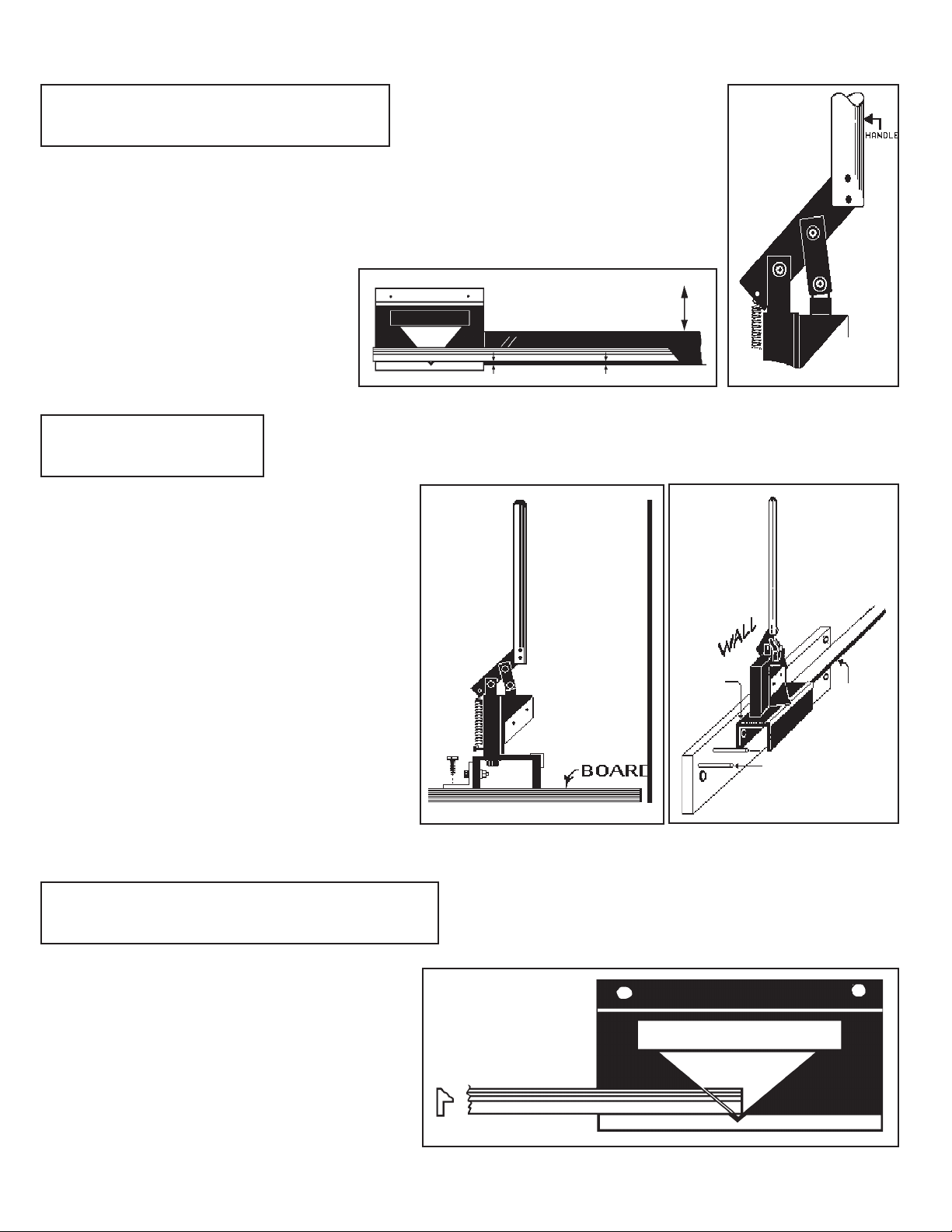
1. Install Handle & Measuring Arm:
Remove the Fillet Cutter unit & handle from the box. Unwrap the handle with the 2 screws
attached. Use the larger allen wrench to attach the handle to the top lever of the machine.
See illustration at right. Mount the measuring arm to the side bracket of the Fillet Cutter
now, before mounting the entire unit to a board or bench.
Be sure to align the measuring arm with
the front angle guide before tightening all
the screws. Use either a piece of llet at
least 36” long or a yardstick for this task
2. Mounting The Unit:
The Fillet Cutter can be mounted directly to a
work bench or attached to a small board for
portability. When mounting to a board, position
the unit to the back of the board so that most of
the wood is in front of the unit. This will eliminate
tipping. A board measuring 6” x 8” x 1/2” thick, is
large enough.You can also mount the unit to a wall
provided there are studs handy to use. It’s best to
rst mount the unit to a 1”x4” board long enough
to span at least 2 studs in your wall. Using a
longer board will allow you to build in some
support for the llet on the infeed side of the unit
as well. Small dowels work well for this.
NOTE: When mounting to a wall, rst remove the
back angle bracket. Mount through the holes in the
base channel to the board, then lag bolt the board
and unit to the studs.
3. Measuring & Cutting Fillet To Length:
STEP 1: Place the llet on the Fillet Cutter with
the at ange portion against the front guide.
Cut off one end to create the rst 45
o
corner

STEP 2 a: If you’re using the measuring arm, after
making your rst edge cut, slide the llet over to the 45
o
ANGLED line that matches the dimension you want to
cut. (Use the vertical step in the llet to measure.)
Bring the Slide Stop over to touch the llet edge. Finger-
tighten the screw on the stop. Check the cut piece of
llet in the mat opening for trimming to exact size.
STEP 2 b: If you’re measuring by hand, place the cut llet under the mat so that the cut end will
t into one corner of the opening. Hold the llet in place with one hand and use the other hand to
mark the llet with an exacto knife or a used mat cutter blade. Make the mark straight across the
llet. Remove the llet from under the mat and continue the mark using the blade to make it easy
to see.
Measure Point Is At Mat Corner
Matboard
Fillet under
the matboard
Hold blade against this side
of mat & rock the blade to
make a mark straight across
the llet. The remainder of marked
llet will be cut off & discarded
STEP 3 b: Place the marked llet onto the Fillet Cutter so the ange is against the front guide. Slide the llet
over, so that the mark is under the blade. Sight down onto the blade to align the mark with the blade edge. Cut
through the llet with a smooth motion. Check the cut rail in the mat opening for t. It should be cut so there is a
small amount of play in the opening. 1/64” to 1/32” is about right, since the other pieces will eventually tighten
the t in the opening. The Fillet Cutter is designed to shave very small amounts from the cut edge so you can get
a perfect t. A little practice will make you an expert in a short time.
Mat opening
Fillet
Flange
Blade edge aligns with cut mark
at the point where the ange starts

4. Sharpening or Replacing Blades:
The two cutter blades are made from tool steel and can be sharpened easily
with an oil stone. (The kind used for sharpening jack knives, etc. and
available at K-Mart or similar stores.) It’s best to use a stone that is 1-1/4” to
1-1/2” wide x 3” to 4” in length. Both blades can be removed using the
small allen wrench supplied with the unit. Please be extremely careful when
handling the blades. The sharp edges can cut easily. Hold the blade with
the bevel against the stone and push forward as shown in the drawing.
Lift the blade slightly on the backstroke and bear down on the forward stroke.
After 10-15 passes on the stone, you can lay the at side against the stone
and gently stroke it forward several times to remove the burr that forms.
DO NOT tip the at side of the blade UP on the stone. This surface must
remain at for an accurate cut. When you’re nished, it’s good practice
to strop the blade edge backwards against a piece of leather, heavy cloth, or
matboard, several times to remove the rolled edge that forms when
sharpening. Remount the blades using the original screws. If your blades
become nicked or damaged beyond repair, replacement sets are available
from your supplier.
5. Adjustments
Although the Fillet Cutter unit comes from the factory fully adjusted, wear on some parts could require that adjust
ments be made in the future. If the vee-block, which moves in the dovetail slide, becomes loose, simply loosen the
screws on one side just a little and tap the guide bar towards the vee-block. Snug the two screws and check for
binding through the entire movement. If it is too tight, tap the vee-block in the opposite direction slightly, and
recheck. If replacement blades do not t exactly the same as the original blades, the vertical block (item #2 in
parts drawing) can be moved by loosening the two bolts under the base channel. Retighten after the correct
alignment is achieved. NOTE: All nuts and bolts are metric.
6. Precautions
The aluminum handle provides for a 10 to 1 mechanical advantage. DO NOT try to increase the length of the
handle with a piece of pipe or other device. Damage to the unit could result from overstressing components in this
way, and will VOID THE WARRANTY! Do NOT cut small wood or aluminum mouldings with this cutter.
Aluminum wrapped wood llets or aluminum core plastic llets can be cut, but will require a second clean-up cut
to get the 45
LIMITED WARRANTY
The manufacturer warrants this equipment to the original Purchaser to be free from defects in material or workmanship for a period of one (1) year from the date of
purchase on the complete machine. This Limited Warranty shall be limited to the repair or replacement, at the sole discretion of the Manufacturer, of any defective
part or parts. In the event of a defect in material or workmanship within the period of this Limited Warranty, Purchaser shall return to Manufacturer’s Warranty Service
Center, TRANSPORTATION PREPAID, the defective equipment.
PROOF AND DATE OF PURCHASE WILL BE REQUIRED ON ANY PRODUCT SO ASSOCIATED WITH ANY WARRANTY CLAIM. Failure of this equipment
caused by accident, corrosion, misuse or abuse of the equipment including but not limited to, damages or defects resulting from improper packaging of returned
equipment or improper repairs made by others, is not covered by this Limited Warranty. Manufacturer reserves the right to determine whether the defect is covered by
this Limited Warranty. If Manufacturer determines that the returned equipment is not covered by this Limited Warranty, then at Purchaser’s option, such equipment
shall be either: 1) returned to Purchaser, TRANSPORTATION COLLECT, or 2) repaired or replaced on the basis of Manufacturer’s regular repair, replacement, or
reconditioning charges, which charges shall be payable by Purchaser, C.O.D.
This Limited Warranty extends only to the initial Purchaser and may not be transferred to subsequent owners.
o
angle correct.
THIS LIMITED WARRANTY IS IN LIEU OF ALL OTHER WARRANTIES, EXPRESS OR IMPLIED INCLUDING ALL IMPLIED WARRANTIES OF
MERCHANTABILITY AND FITNESS FOR A PARTICULAR USE AND PURPOSE. PURCHASER AGREES THAT THE SOLE AND EXCLUSIVE REMEDY
AGAINST MANUFACTURER SHALL BE LIMITED TO THE REPAIR OR REPLACEMENT OF
DEFECTIVE PARTS. PURCHASER FURTHER AGREES THAT NO OTHER REMEDY, INCLUDING BUT NOT LIMITED TO INCIDENTAL OR
CONSEQUENTIAL DAMAGES FOR LOST PROFITS, LOST SALES, INJURY TO PERSON OR PROPERTY, OR ANY OTHER INCIDENTAL OR
CONSEQUENTIAL LOSS, SHALL BE AVAILABLE TO IT, AND, IN ANY EVENT, THE LIABILITY OF MANUFACTURER FOR ANY DAMAGES SHALL BE
LIMITED TO THE PURCHASE PRICE OF THE EQUIPMENT.


 Loading...