

Page 1
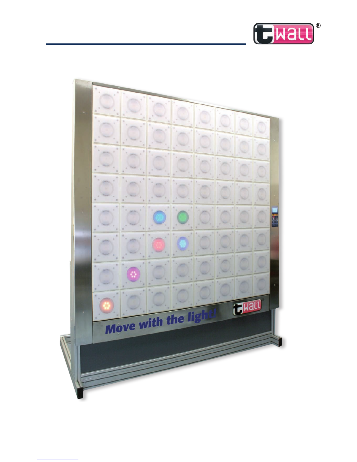
twall®Premium64 mobile / stationary
Interactive sports and training device
User manual
Rev. 4.0
Data-CD
Page 2

Page 3

D| 3
twall®Premium64 mobile / stationary User manual | Rev. 4.0
Table of contents:
Hardware documentation
1 Product description---------------------------------------------------------------------------------------- 4
1.1 Handling according to regulations ----------------------------------------------------------------------------4
2 Scope of delivery ------------------------------------------------------------------------------------------- 5
2.1 Overview - scope of delivery of the twall®Premium64 mobile -------------------------------------------5
2.1.1 Detailed list of components including assembling steps --------------------------------------------------5
2.2 Overview - scope of delivery of the twall®Premium64 stationary --------------------------------------7
2.2.1 Detailed list of components including assembling steps --------------------------------------------------7
3 Assembly ------------------------------------------------------------------------------------------------------- 9
3.1 Mobile installation of the twall®Premium64 ----------------------------------------------------------------9
3.1.1 Storage space requirements ------------------------------------------------------------------------------------9
3.1.2 Assembly principle of the profile connectors ---------------------------------------------------------------9
3.1.3 Assembly instructions ----------------------------------------------------------------------------------------- 10
3.1.3.1 Assembling the frame base ---------------------------------------------------------------------------------- 10
3.1.3.2 Assembling the aluminium frame -------------------------------------------------------------------------- 12
3.1.3.3 Assembling the basic modules------------------------------------------------------------------------------- 15
3.2 Stationary installation of the twall®Premium64 ------------------------------------------------------------ 18
3.2.1 Storage space requirements --------------------------------------------------------------------------------- 18
3.2.2 Assembly instructions ----------------------------------------------------------------------------------------- 18
3.2.2.1 Assembling the aluminium frame -------------------------------------------------------------------------- 18
3.2.2.2 Assembling the basic modules------------------------------------------------------------------------------- 22
4 Maintenance -------------------------------------------------------------------------------------------------22
5 Troubleshooting -------------------------------------------------------------------------------------------22
6 Technical specifications ---------------------------------------------------------------------------------23
6.1 Data sheet
twall
®
Premium64 mobile and stationary ---------------------------------------------------- 23
6.2 Data sheet - Accessories -------------------------------------------------------------------------------------- 23
Software documentation
7 Operating twall® using control panel --------------------------------------------------------------24
7.1 Executing twall® programs ---------------------------------------------------------------------------------- 24
7.2 Viewing highscores -------------------------------------------------------------------------------------------- 25
7.3 Settings ---------------------------------------------------------------------------------------------------------- 25
8 Operating
twall
®
using computer --------------------------------------------------------------------26
8.1 Connecting twall® to computer ----------------------------------------------------------------------------- 26
8.2 Driver installation ---------------------------------------------------------------------------------------------- 26
8.2.1 Installing drivers using Microsoft Windows XP® -------------------------------------------------------- 26
8.2.2 Installing drivers using Microsoft Windows Vista® ------------------------------------------------------- 27
8.3 Software installation ------------------------------------------------------------------------------------------ 28
8.4 Software description ------------------------------------------------------------------------------------------ 29
8.4.1 The welcome page -------------------------------------------------------------------------------------------- 29
8.4.2 Program settings ----------------------------------------------------------------------------------------------- 29
8.4.3 Executing twall® programs ---------------------------------------------------------------------------------- 29
8.4.3.1 Saving programs to twall® ---------------------------------------------------------------------------------- 30
8.4.3.2 Highscores ------------------------------------------------------------------------------------------------------ 31
8.4.4 Simulating twall® programs --------------------------------------------------------------------------------- 31
8.4.5 Creating new twall® programs ------------------------------------------------------------------------------ 32
8.4.6 Editing twall® programs -------------------------------------------------------------------------------------- 34
8.4.7 Editing Sound sets --------------------------------------------------------------------------------------------- 34
8.5. Firmware update ----------------------------------------------------------------------------------------------- 35
9 Standard twall® programs ------------------------------------------------------------------------------36
Appendix: Handout
Page 4

4 |D
twall®Premium64 mobile / stationary User manual | Rev. 4.0
Hardware documentation
1 Product description
The twall® is an interactive sports device using light pulses to specifically initiate motion
sequences. At a wall consisting of evenly arranged, large pads, colored signals light up (available
separately as well as in combination) and have to be deactivated by touching them again which
defines sterical movements. Depending on the training sequence used condition, agility, the
ability to respond, and if required specific muscular endurance can be trained. The different
elements can be predefined in the program so that they light up in a selective or random
sequence, position and speed. The task is always the same: To deactivate the light as quickly as
possible by pressing the buttons.
The software-controlled program sequences provide both individual training and group training.
By controlling each touch element individually it is possible to adjust the twall® training settings
according to size, sphere of activity, visual perception as well as the tactile situation of the
person trained. Furthermore, product version twall® color allows to integrate cognitive tasks
using various colors and sounds. Also, the small construction depth makes it easy to integrate
twall® to existing room concepts.
1.1 Handling according to regulations
The use of the twall® is intended for training and game purposes of human beings exclusively.
It is strictly recommended that the operator checks if the aptitude of the training program suits
the training person. The twall® has to be operated by the provided power supply unit only.
As a precaution we would like to make you aware of the fact that the twall® control panel
generates high frequency, electric oscillations and despite compliance with legal regulations it
may effect other electronic devices such as cardiac pacemakers etc.
Please be aware that the fastening of the twall® has to be secured on site and is not within the
manufacturers obligation. The applicability of the walls should be checked and plasterboard
walls should be covered at least twice. Fixing elements such as screw anchors and tie bars must
have adequate tensile strength.
The fastening should be checked on a regular basis. In the case that fixing elements become
loose the twall® must not be used any further until the fastening has been repaired entirely.
Continuous operation of a single or all touch pads is not permitted as it can lead to a strong
heating of the LED (light-emitting diode) modules. Sequences that force a single or all touch
pads to light up for longer than 2 minutes are prohibited and can cause the loss of warranty.
Page 5

D| 5
twall®Premium64 mobile User manual | Rev. 4.0
2 Scope of delivery
2.1 Overview - scope of delivery of the twall®Premium64 mobile
A1 1 x Frame base
A2 1 x Aluminium frame
A3 4 x twall® Basic modules
A4 4 x Weights
B1 1 x Stainless steel frame cover left
B2 1 x Stainless steel frame cover right incl. control panel with power
supply jack and power supply switch (connections for further equipment such
as loudspeakers or headsets are available)
B3 2 x Stainless steel frame covers (top/bottom)
C Accessories (included in scope of delivery)
D Required tools (not included in scope of delivery)
E User manual and data-CD
2.1.1 Detailed list of components including assembling steps
A1 1 x Frame base consisting of:
A1a 1 x Frame base profile 45 x 90 x 2023 mm | 1.77 x 3.54 x 79.65 inch
A1b 1 x Frame base profile 45 x 90 x 1933 mm | 1.77 x 3.54 x 76.10 inch
A1c 2 x Frame base profiles 45 x 90 x 1055 mm | 1.77 x 3.54 x 41.54 inch
A1d 2 x Frame base profiles 45 x 90 x 910 mm | 1.77 x 3.54 x 35.83 inch
A1e 4 x Profile angles 30 x 30 x 5 mm | 1.18 x 1.18 x 0.20 inch
A1f 4 x Joints for the angles braces
A1g 2 x Angles braces 45 x 45 x 1900 mm | 1.77 x 1.77 x 74.80 inch
Assembling the frame base – three steps:
I. Mounting the frame base profiles
20 x Profile connectors (of which 4 are provided for the side supports at the aluminium frame)
4 x Rubber feet (black, adhesive)
4 x Cover caps (black, plastic)
II. Attaching the profile angles to the frame base
12 x Fillister head screws with flange M8x16 (3 per angle)
12 x T-nuts M8 (3 per angle)
III. Fastening the joints to the angles braces
16 x Adjusting blocks for the joints
4 x Joints for angle braces
4 x Socket head screws M8x25 to fit the joints to the angle braces
4 x Washers
4 x Socket head screws M8x16 to fit the joints to the frame base and the aluminium frame
4 x Washers
4 x T-nuts M8 to fit the joints to the frame base and the aluminium frame
A2 1 x Aluminium frame consisting of:
A2a 2 x Side supports 45 x 90 x 2250 mm | 1.77 x 3.54 x 88.58 inch
A2b 1 x Shield 8 mm | 0.32 inch
A2c 4 x Frame profiles long 45 x 45 x 1933 mm | 1.77 x 1.77 x 76.10 inch
(of which one with pre-assembled PVC installation channel)
A2d 2 x Frame profiles short 45 x 45 x 840 mm | 1.77 x 1.77 x 33.07 inch
A2e 8 x Profile angles 28 x 28 mm | 1.10 x 1.10 inch
Page 6
6 |D
twall®Premium64 mobile User manual | Rev. 4.0
Assembling the aluminium frame – three steps:
I. Mounting the frame profiles
8 x Profile connectors
2 x Cover caps (black, plastic)
4 x Combination profiles (grey, PVC)
II. Attaching the profile angles to the frame profiles
16 x Fillister head screws with flange (2 per angle)
16 x T-nuts M6
III. Fastening the angles braces
(Components included in part )
A3 4 x Basic modules consisting of:
A3a 1 x Basic module top left with manifold PCB (printed circuit board)
A3b 1 x Basic module bottom left
A3c 1 x Basic module top right with manifold PCB with line filter
A3d 1 x Basic module bottom right
Assembling the basic modules – two steps:
I. Setting up the basic modules
8 x Socket head screws M8x30
8 x Washers
8 x T-nuts M8
II. Connecting the basic modules to the control panel
16 x 14-stranded flat ribbon cables to connect to the manifold PCBs marked as
0.1 - 0.4, 1.1 - 1.4, 2.1 - 2.4 and 3.1 - 3.4
2 x 26-stranded flat ribbon cables to connect to the control panel (marked as A and B)
1 x double-pole power supply cable including connectors 1 and 2 in pre-assembled
PVC installation channel
A4 4 x Weights
B1 1 x Stainless steel frame cover left
B2 1 x Stainless steel frame cover right
incl. control panel with power supply jack and power supply switch
(connections for further equipment such as loudspeakers or headsets are available)
B3 2 x Stainless steel frame covers (top/bottom)
Assembling the stainless steel frame covers:
11 x Fillister head screws M6x10
C Accessories (included in scope of delivery)
C1 1 x Power supply line (with Euro connector)
C2 1 x USB cable (A/B)
C3 1 x Adapter (power supply unit)
C4 1 x Set of Allen keys (4 mm, 5 mm and 6 mm | 0.16 inch, 0.20 inch and 0.24 inch)
D Required tools (not included in scope of delivery)
Stepladder
Spirit level
Measuring tape
Slot screwdriver 9 mm | 0.35 inch
E User manual and data-CD
Page 7

D| 7
twall®Premium64 stationary User manual | Rev. 4.0
2.2 Overview - scope of delivery of the twall®Premium64 stationary
A2 1 x Aluminium frame
A3 4 x twall® Basic modules
B1 1 x Stainless steel frame cover left
B2 1 x Stainless steel frame cover right
incl. control panel with power supply jack and power supply switch
(connections for further equipment such as loudspeakers or headsets are available)
B3 2 x Stainless steel frame covers (top/bottom)
C Accessories (included in scope of delivery)
D Required tools (not included in scope of delivery)
E User manual and data-CD
2.2.1 Detailed list of components including assembling steps
A2 1 x Aluminium frame consisting of:
A2a 2 x Side supports 45 x 90 x 2250 mm | 1.77 x 3.54 x 88.58 inch
A2b 1 x Shield 8 mm | 0.32 inch
A2c 4 x Frame profiles long 45 x 45 x 1933 mm | 1.77 x 1.77 x 76.10 inch
(of which one with pre-assembled PVC installation channel)
A2d 2 x Frame profiles short 45 x 45 x 840 mm | 1.77 x 1.77 x 33.07 inch
A2e 8 x Profile angles 28 x 28 mm | 1.10 x 1.10 inch
A2f 4 x Angles for wall fastening 86 x 86 x 43 mm | 3.39 x 3.39 x 1.69 inch
Assembling the aluminium frame – four steps:
I. Mounting the frame profiles
8 x Profile connectors
2 x Cover caps (black, plastic)
4 x Combination profiles (grey, PVC)
II. Attaching the profile angles to the frame profiles
16 x Fillister head screws with flange M6x14 (2 per angle)
16 x T-nuts M6
III. Attaching the angles for wall fastening
8 x Verbus-Ripp-screws M8x20 (hexagon socket)
8 x T-nuts M8
IV. Setting up the aluminium frame
4 x Plastic dowels 10x70
4 x Hexagon head wood screws 10x100
A3 4 x Basic modules consisting of:
A3a 1 x Basic module top left with manifold PCB (printed circuit board)
A3b 1 x Basic module bottom left
A3c 1 x Basic module top right with manifold PCB and line filter
A3d 1 x Basic module bottom right
Assembling the basic modules – two steps:
I. Setting up the basic modules
8 x Socket head screws M8x30
8 x Washers
8 x T-nuts M8
Page 8

8 |D
twall®Premium64 stationary User manual | Rev. 4.0
II. Connecting the basic modules to the control panel
6 x 14-stranded flat ribbon cables to connect to the manifold PCBs marked as
0.1 - 0.4, 1.1 - 1.4, 2.1 - 2.4 and 3.1 - 3.4
2 x 26-stranded flat ribbon cables to connect to the control panel
(marked as A and B)
1 x double-pole power supply cable including connectors 1 and 2 in
pre-assembled PVC installation channel
B1 1 x Stainless steel frame cover left
B2 1 x Stainless steel frame cover right
incl. control panel with power supply jack and power supply switch
(connections for further equipment such as loudspeakers or headsets are available)
B3 2 x Stainless steel frame covers (top/bottom)
Assembling the stainless steel frame covers:
11 x Fillister head screws M6x10
C Accessories ((included in scope of delivery)
C1 1 x Power supply line (with Euro connector)
C2 1 x USB cable (A/B)
C3 1 x Adapter (power supply unit)
C4 1 x Set of Allen keys (4 mm, 5 mm and 6 mm | 0.16 inch, 0.20 inch and 0.24 inch)
D Required tools (not included in scope of delivery)
Stepladder
Spirit level
Measuring tape
Hammer drill
Drill bit 12 mm | 0.47 inch
Wrench 17 mm | 0.67 inch
E User manual and data-CD
Page 9
D| 9
twall®Premium64 mobile User manual | Rev. 4.0
3 Assembly
ATTENTION: Before start-up a period of 1-2 hours is advised for the equipment to acclimatize. Please pay
attention to condensation that might appear.
3.1 Mobile installation of the twall®Premium64
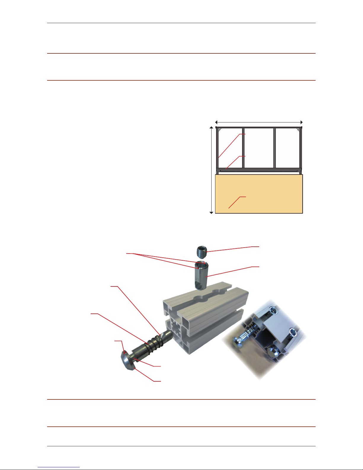
3.1.1 Storage space requirements
In order to set up the twall® a compact and
even stand space of a minimum of
3 x 3 m | 118.11 x 118.11 inch is required
(fig. 3.1-1). It must carry a weight of at
least 231 kg | 36.4 stone.
At least 2 people and the following tools
are required:
Allen keys (included in scope of delivery)
Stepladder
Spirit level
Measuring tape
Slot screwdriver 9 mm | 0.35 inch
3.1.2 Assembly principle of the profile connectors
fig. 3.1-1
3 m | 118.11 inch
3 m | 118.11 inch
Training area
twall
®
Frame Base
Cross piece
Set screw (with
hexagon socket)
Anchor
Mark at the anchor
(should point towards
the cross piece)
Mark at the cross piece
(should point towards
the anchor)
Chamfering
Spring
fig. 3.1-2
Anchor neck
PLEASE NOTE: For more information, please see view of individual assembling steps on separate handout.
Page 10
10 |D
twall®Premium64 mobile User manual | Rev. 4.0
3.1.3 Assembly instructions
3.1.3.1 Assembling the frame base
I. Mounting the frame base profiles:
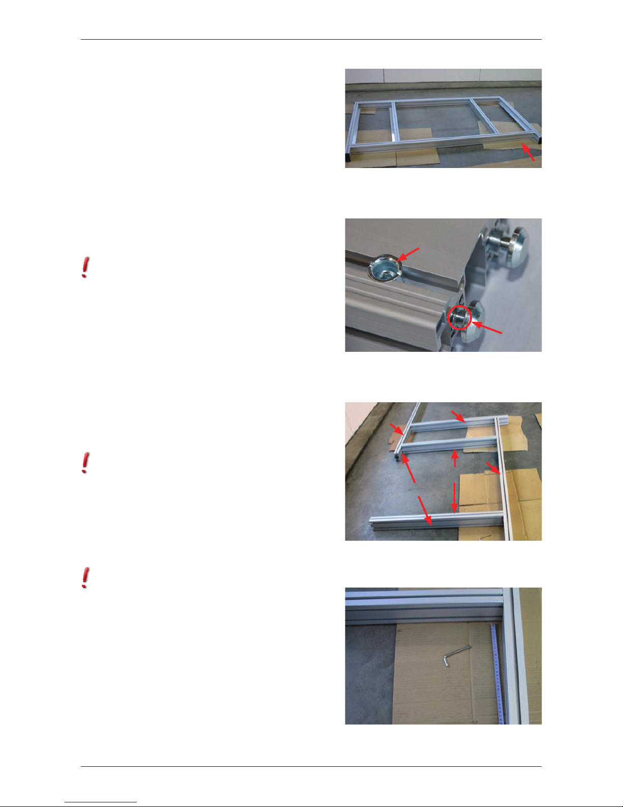
Step Please remove the packaging
material. You can use it as a pad during the
assembly to avoid that the components are
scratched or damaged.
Step Before you start putting together
the frame base A1 (fig. 3.1-3), please attach
all the profile connectors to the provided
positions at the frame base profiles first. Four
(4) profile connectors should be kept for the
side supports of the aluminium frame.
In order to fasten the profile connectors, the
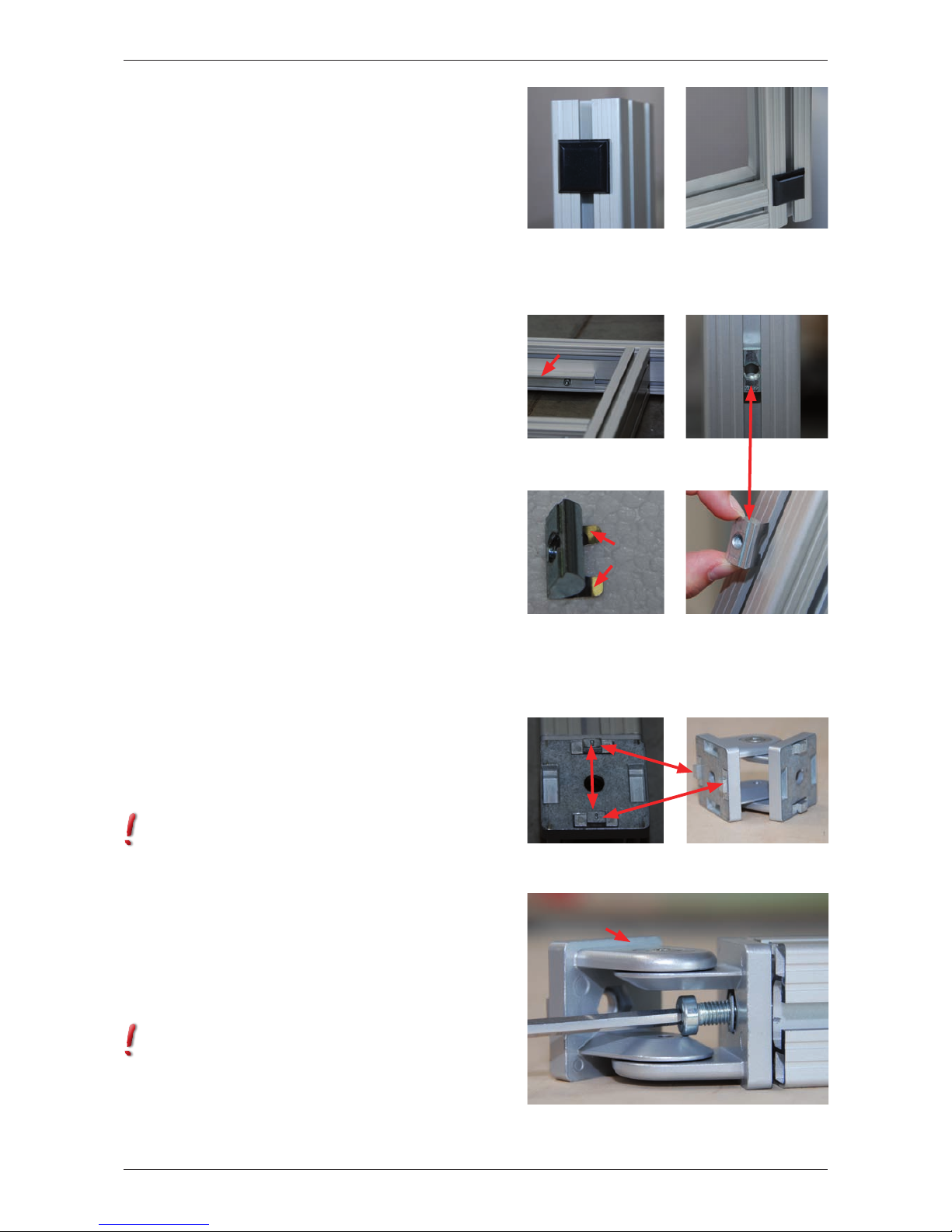
chamfering should point towards the cross
piece which is indicated by the mark at the
anchor (fig. 3.1-2). The set screw will be
slightly screwed into the cross piece with
the corresponding Allen key. The anchor will
be drawn into the profile automatically. It is
important that you can still see the neck of the
anchor (fig. 3.1-4) to be able to insert it into
the lead channels at a later point (fig. 3.1-5).
It might be the case that you need to push the
anchor slightly against the cross piece while
screwing it in.
Step Shove the two (2) frame base
profiles A1d into the lead channels of the
frame profiles A1a and A1b (fig. 3.1-5).
Please ensure that the cross pieces of the
connectors in the frame base profiles A1d
point inwards and the cross pieces of the
connectors in the frame base profile A1b
point outwards.
Step Now shove the frame base
profiles A1c , one to the right and to the
left, into the lead channels of the frame base
profile A1a.
Align the outer edges of the profiles so they
can be flush-mounted. The cross pieces of
the connectors should point outwards. Now
tighten the profile connectors with the corres-
ponding Allen key (ca. 25 Nm).
Step Measure the distance between
the frame base profiles A1c and A1d zuein-
ander. The distance has to be 42 cm (16.54
inch) between the inner edges. Once you have
fastened the frame base profiles A1c and A1d
you can strongly bolt together all other profile
connectors (ca. 25 Nm). (fig. 3.1-6).
fig. 3.1-6
fig. 3.1-5
A1a
A1b
A1d
A1c
User´s view
Lead channels
fig. 3.1-3
User´s view
fig. 3.1-4
Anchor neck
Cross piece
Page 11
D| 11
twall®Premium64 mobile User manual | Rev. 4.0
Step Put the frame base in an upright
position in order to attach the four (4) rubber
feet to the bottom of the frame base. (fig.
3.1-7 and 3.1-8) The projecting profiles
should point upwards. Remove the protection
film at the rubber feet and position the
adhesive feet at the outer lower edges of the
frame base profiles A1c.
II. Attaching the profile angles to the
frame base:
Step The four (4) profile angles A1e
will be fitted to the inner sides of the frame
base profiles A1c and A1d (fig. 3.1-9). Place
the twelve (12) T-nuts M8 in the lower lead
channels of the frame base profiles A1c and
A1d (3 T-nuts per side and angle respectively).
Insert the T-nuts by half-twisting them into
the lead channels with the spring ahead (fig.
3.1-10 and 3.1-11).
Roughly estimate the concentric position of
the profile angles and align the T-nuts approp-
riately. Since the weights will be placed on the
profile angles, the angle should be attached
with the surface pointing towards you. Screw
on the profile angles using the T-nuts and the
twelve (12) fillister head screws M8x16 with
flange (3 per angle).
III. Fastening the joints to the angles
braces:
Step At first, the four (4) threaded
inserts will be screwed into the open ends
of the angles braces (A1g) using a 9 mm |
0.35 inch slot screwdriver. In order to attach
the joints to the angles braces, put two (2)
adjusting blocks opposite of each other into
the provided holes.
It is very important to insert the adjusting
blocks into the holes at the sides where the
arms of the joints are located and that the
number 8 on top of the adjusting blocks
points outwards. (fig. 3.1-12 and fig.
3.1-13). You will find that the adjusting blocks
marked with number 8 will fit exactly into
the lead channels. Now position the joints at
the ends of the angles braces and bolt them
together using the four (4) socket head screws
M8x25, the washers and the corresponding
Allen key. (Abb. 3.1-14).
Please take care to mount all joints to the
angles braces facing the same direction. To
simplify the process, we would recommend
attaching the angles braces to the frame base
once having assembled the aluminium frame.
fig. 3.1-8fig. 3.1-7
fig. 3.1-12
fig. 3.1-13
fig. 3.1-14
Arms of
the joints
fig. 3.1-9
Profile
angles
fig. 3.1-11 fig. 3.1-11
fig. 3.1-10
Spring
Page 12
12 |D
twall®Premium64 mobile User manual | Rev. 4.0
3.1.3.2 Assembling the aluminium frame
I. Mounting the frame profiles:
The aluminium profile serves as the frame
of the twall® in order to be installed free-
standing. (fig. 3.1-15).
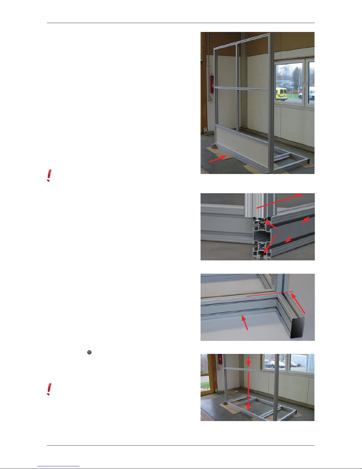
Step Place the frame base A1 with
the rubber feet at the lower side the way that
the projecting profiles A1c are facing you
(fig. 3.1-15). To ensure the twall® is firm
and stable a compact and even stand space is
required.
Before you start putting together the
aluminium frame, please attach all the profile
connectors to the provided positions at the
frame profiles. Four (4) profile connectors
were kept earlier (see step 2) to be fastened to
the side supports of the aluminium frame.
In order to fasten the profile connectors, the
chamfering should point towards the cross
piece which is indicated by the mark at the
anchor (fig. 3.1-2). The set screw will be
slightly screwed into the cross piece with the
corresponding Allen key. The anchor will be
drawn into the profile automatically.
It is important that you can still see the neck
of the anchor to be able to insert it into the
lead channels at a later point (fig. 3.1-16). It
might be the case that you need to push the
anchor slightly against the cross piece while
screwing it in.
Step Shove the side supports A2a
from the front into the lead channels of the
frame base (fig. 3.1-16). Please make sure
that the cross pieces of the profile connectors
at the side supports point outwards. The side
supports have to be on the same level as the
frame base profile A1c and need to be flush-
mounted (fig. 3.1-17). Now tighten the
profile connectors with the corresponding
Allen key (ca. 25Nm). Finally, attach the four
(4) black cover caps at the ends of the frame
base profiles A1c and. A1a.
Step
11
Insert a long frame profile A2c
into the front lead channel between the side
supports, move it down to the frame base and
bolt it together with the profile connectors
(fig. 3.1-18).
The cross pieces of the profile connectors
should point backwards.
fig. 3.1-15
User´s view
fig. 3.1-16
Lead
channels
fig. 3.1-17
User´s view
fig. 3.1-18
Page 13
D| 13
twall®Premium64 mobile User manual | Rev. 4.0
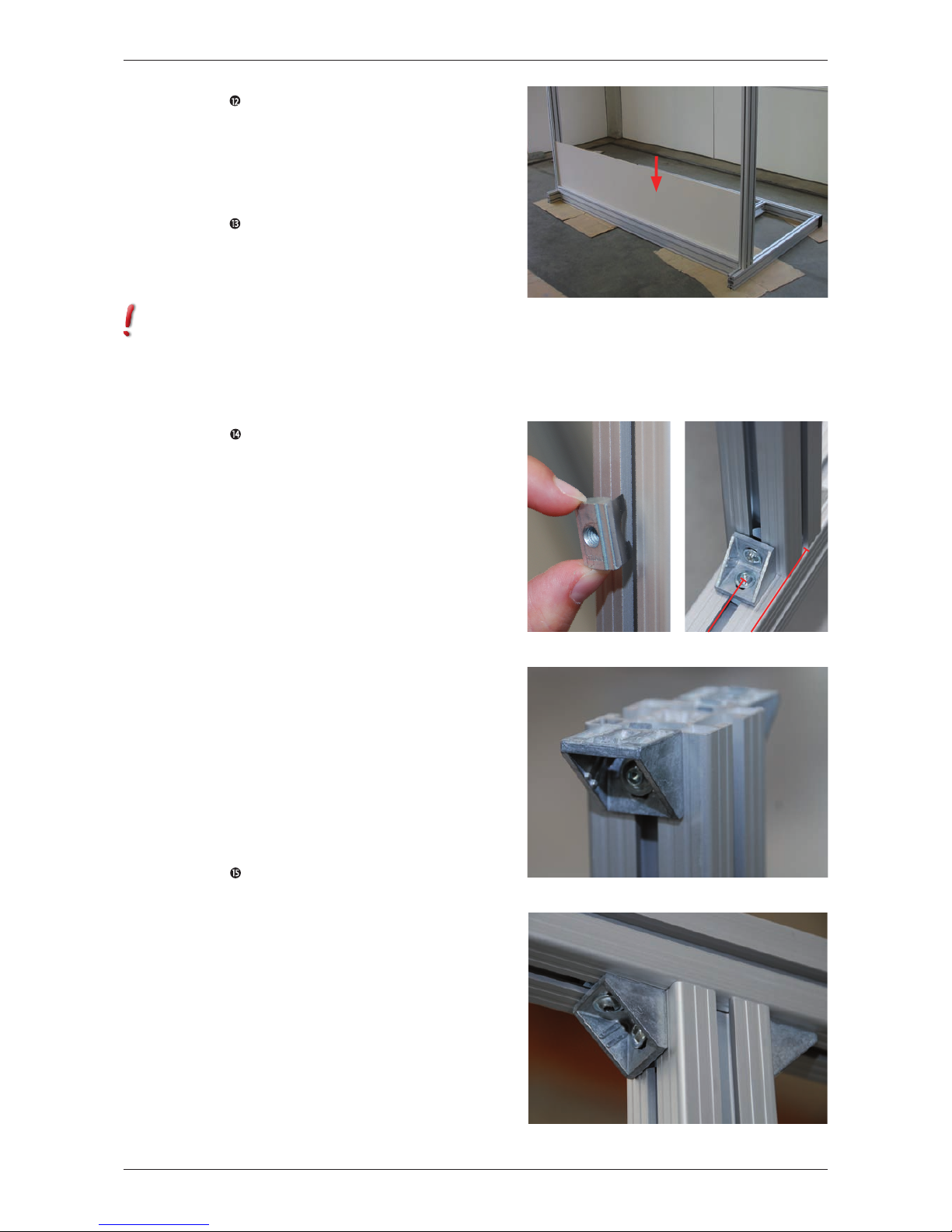
Step 12 Shove the shield A2b into the
front lead channel between the side supports
down to the long frame profile A2c. (fig.
3.1-19). The shield (8 mm | 0.32 inch) should
click exactly into the lead channel of the frame
profile.
Step 13 Then insert another long frame
profile A2c into the front lead channel
between the side supports and move it down
to the shield A2b which should click into the
lead channel at the top.
The cross pieces of the profile connectors
should point backwards again. Please tighten
the profile connectors (ca. 25Nm).
II. Attaching the profile angles to the
frame profiles:
Step 14: In order to attach the profile
angles A2e, you will need sixteen (16) fillister
head screws with flange M6x14 (2 per angle)
and sixteen (16) T-nuts M6.
Measure the long frame profile A2c which you
have just mounted to the shield. There are 930
mm | 38.07 inch from to inner edge of the
side supports to the middle of the screws the
profile angles will be screwed on with. Now
place two (2) T-nuts in the upper lead channel
of the long frame profile. Insert the T-nuts by
half-twisting them into the lead channels with
the spring ahead and align them appropriately
(Abb. 3.1-20). Now insert two (2) T-nuts into
the lead channels of the short frame profile
A2d, 1 x at the bottom left and 1 x at the
bottom right. There are 967 mm | 38.07
inch from the inner edge of the side supports
to the middle of the lead channel. Place the
short frame profile A2d in the middle of the
long frame profile A2c and attach the profile
angles A2e, one to each side using the fillister
head screws with flange (fig. 3.1-21). Tighten
it properly with the corresponding Allen key.
Step 15 Insert two (2) T-nuts into the
just assembled short frame profile again, this
time 1 x at the top left and 1 x at the top
right. Afterwards shove the long frame profile
A2c with the pre-assembled PVC instal-
lation channel into the front lead channel
between the side supports, move it down until
it seats on the vertically placed short frame
profile. The PVC installation channel should
point backwards.
Now insert two (2) T-nuts into the lower
leading channel of the long frame profile and
align them as follows:
From each side measure a distance of 930
mm | 36.61 inch from the inner edge of the
fig. 3.1-22
fig. 3.1-19
fig. 3.1-23
fig. 3.1-21fig. 3.1-20
930 mm
967 mm
Page 14
14 |D
twall®Premium64 mobile User manual | Rev. 4.0
side supports to the middle of the screws the
profile angles will be screwed on with. Attach
two (2) profile angles A2e to the long and
the short frame profiles again (fig. 3.1-22
and 3.1-23). Afterwards tighten the profile
connectors of the long frame profile A2c with
a corresponding Allen key (ca. 25Nm).
Please pay attention to a horizontal alignment
of the frame profile so that a correct
placement of the basic modules is ensured
(spirit level).
Step 16 Please go back to step 14 and 15
and repeat the procedure with the remaining
frame profiles A2c and A2d.
III. Fastening the angles braces:
Now you need to attach the angles braces
A1g to the rear part of the frame base A1
and the rear side of the side supports A2a
(fig. 3.1-24).
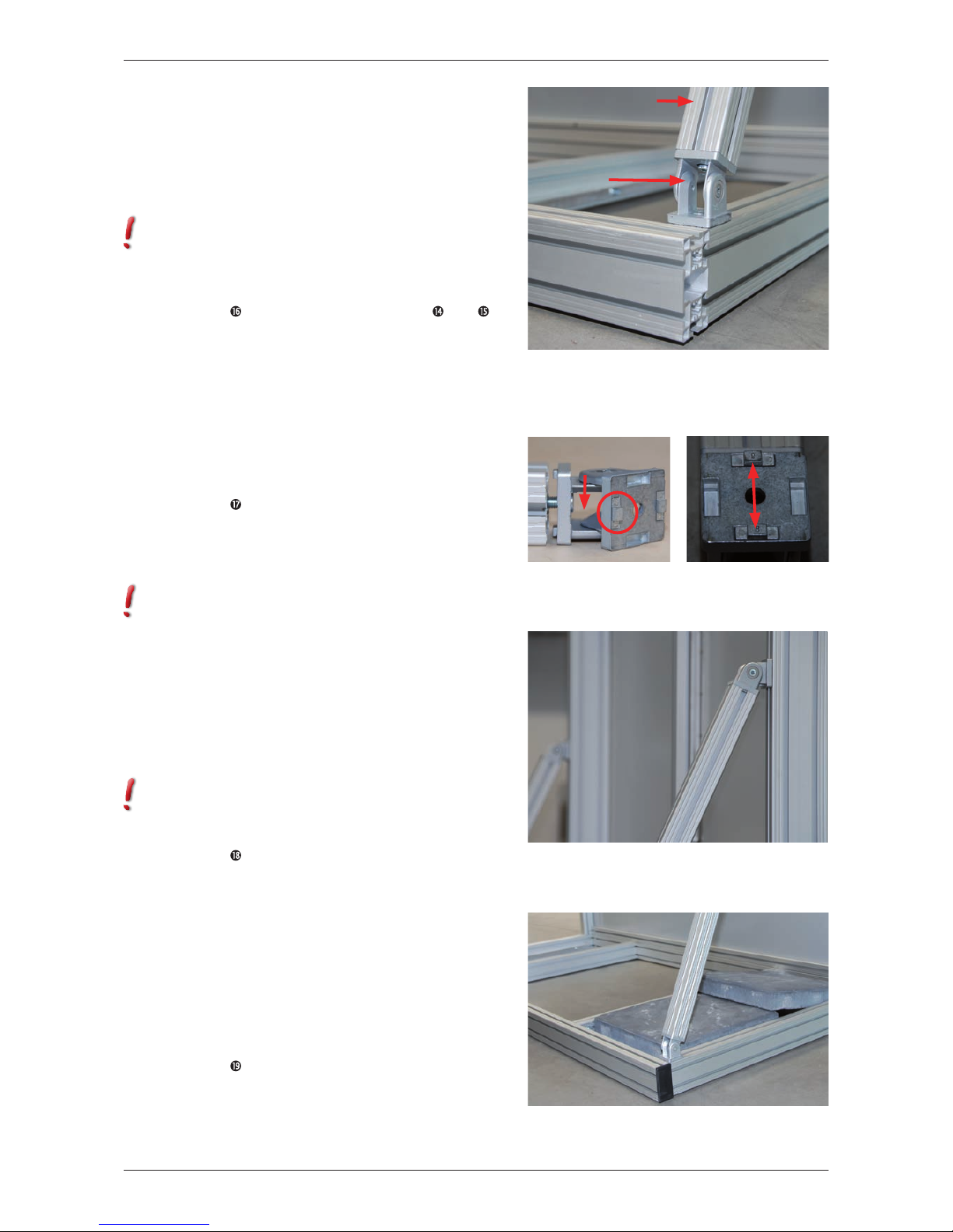
Step 17 Place a T-nut into the lead
channels at each side of the frame base
profiles A1c. Put two (2) adjusting blocks
opposite of each other into the provided holes
of the joints.
This time it is very important to insert the
adjusting blocks into the holes at the open
sides of the joints (not the sides where the
arms are located) (fig. 3.1-25). The number
8 on top of the adjusting blocks have to point
outwards again (fig. 3.1-26). They will fit
exactly into the lead channels. Now position
the joints at the frame base profiles A1c and
bolt them together using two (2) socket head
screws M8x16, two (2) washers and the
corresponding Allen key.
To make the assembly a bit easier for you, we
would advise to place the other ends of the
angle braces backwards.
Step 18 In order to fit the other ends of
the angles braces A1g to the side supports
(fig. 3.1-27) you need to insert two (2) T-nuts
M8 into the lead channels at the rear side
of the side supports (one T-nut per side) and
position the adjusting blocks, as described
above, in the remaining holes of the joints.
Now bolt the joints at the angles braces to the
side supports using the remaining socket head
screws M8x16 and the washers and tighten
them properly.
Step 19 Place the weights A4 at the rear
side of the frame base (fig. 3.1-28). Please be
aware of the industrial safety regulations
(20 kg | 44 lbs per weight).
fig. 3.1-27
fig. 3.1-24
Frame base
profiles
Angle brace
Joint
fig. 3.1-25 fig. 3.1-26
Open side of
the joints
fig. 3.1-28
Page 15
D| 15
twall®Premium64 mobile User manual | Rev. 4.0
Step 20 Finally, put the two (2) black
cover caps on the top ends of the side
supports and press the four (4) grey PVC
combination profiles into the outward lead
channels of the side supports (above the cross
pieces of the profile connectors, 2 x at the
right side and 2 x at the left side).
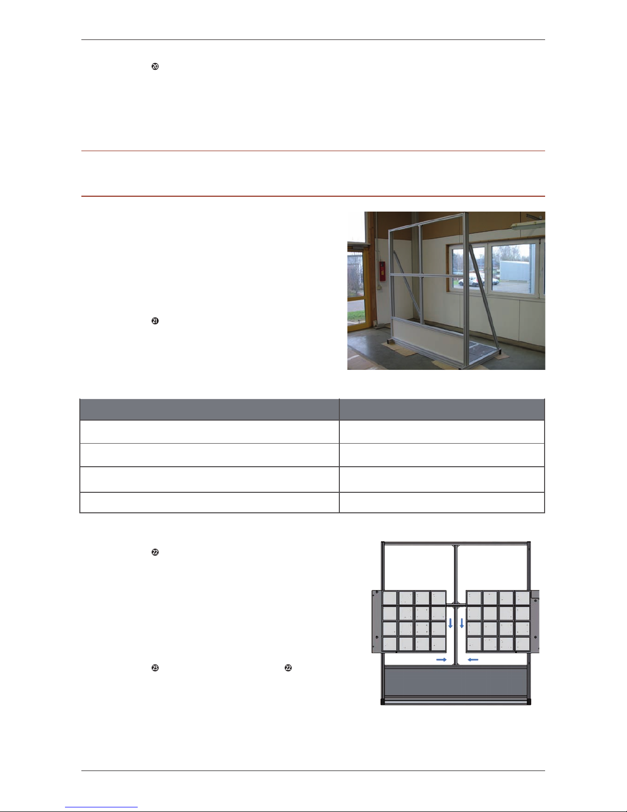
3.1.3.3 Assembling the basic modules
If you have done all these steps, it must look
like in fig. 3.1-29. Now you can start with
setting up the basic modules.
I. Setting up the basic modules:
Step 21 Before you start mounting the
basic modules, please insert all eight (8) T-nuts
M8 required into the front lead channels of
the side supports. For this purpose, you will
need to measure the distances of the T-nuts to
each other and align them:
Step 22 The basic modules A3a bis
A3d are marked bottom right (UR), bottom
left (UL), top right (OR) and top left (OL).
Insert the two lower basic modules into the
frame construction using the z-profiled plates
attached to the rear of each module (fig.
3.1-30). ). The basic modules will be fixed
with two (2) provided socket head screws
M8x30 and two (2) washers for each module.
Step 23 Please go back to step 22 and
repeat the procedure with the upper basic
modules.
Distance: twall®Premium64 mobile
From the floor to the middle of the 1
st
T-nut 579,5 mm | 22.81 inch
From the floor to the middle of the 2nd T-nut 1239,5 mm | 48.80 inch
From the floor to the middle of the 3rd T-nut 1489,5 mm | 58.64 inch
From the floor to the middle of the 4th T-nut 2179,5 mm | 85.81 inch
Abb. 3.1-30
A3b
A3d
A3a
A3c
fig. 3.1-29
PLEASE NOTE: Once having finished the assembly of the aluminium frame, please check whether all profile
connectors at the frame base and the aluminium frame are bolted together strongly (ca. 25Nm).
Page 16
16 |D
twall®Premium64 mobile User manual | Rev. 4.0
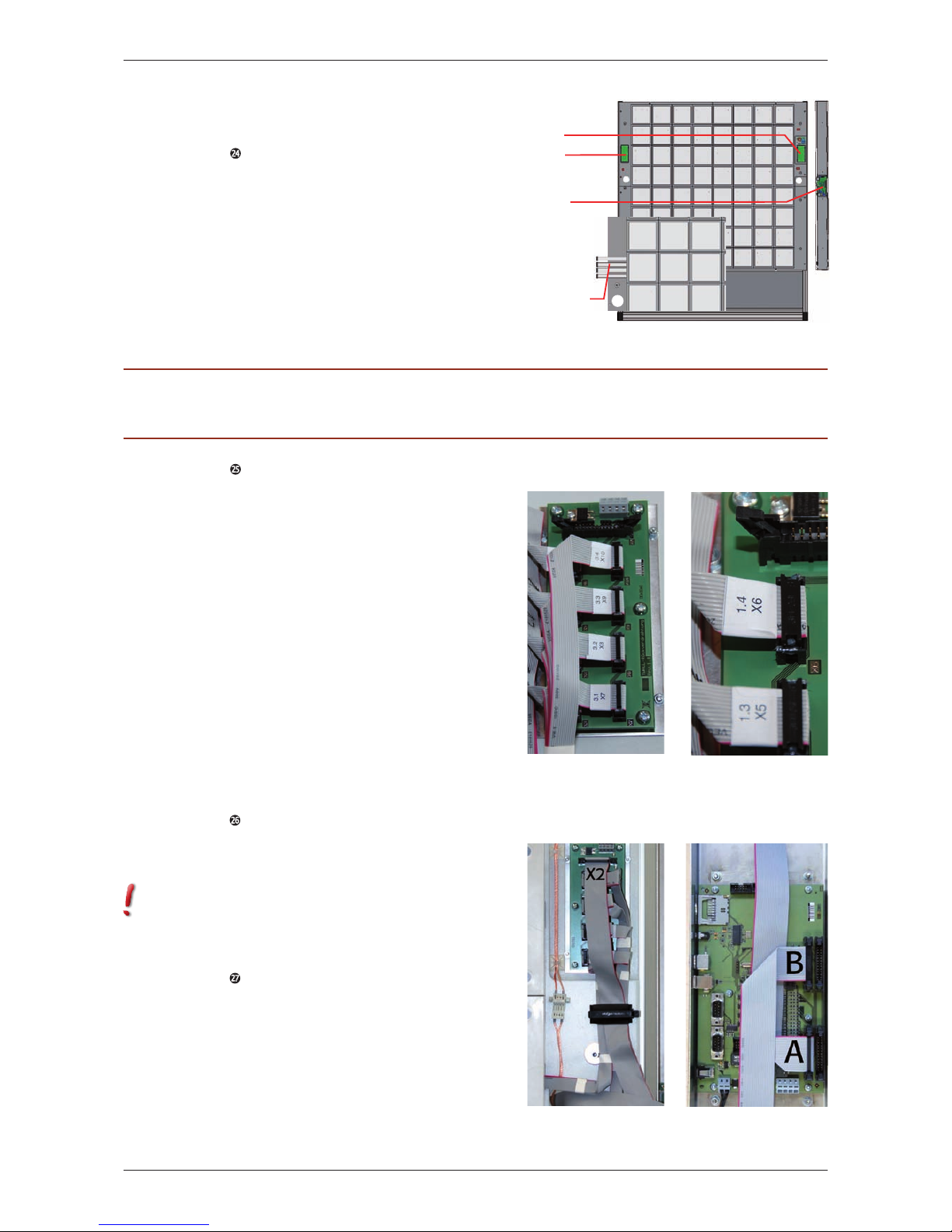
II. Connecting the basic modules to
the control panel:
Step 24 You can find four (4)
14-stranded flat ribbon cables at each basic
module to connect them to the manifold
PCBs (fig. 3.1-32 and 3.1-33). The cables
are marked as 0.1 - 0.4, 1.1 - 1.4, 2.1 - 2.4
and 3.1 - 3.4 as well as the appropriate plug
number. Now put the flat ribbon cables on
the manifold PCBs. The PCB for the two (2)
right basic modules can be found at the right
upper basic module, the PCB for the two (2)
left basic modules are located at the left upper
basic module (fig. 3.1-31).
Step 25: Then connect the manifold
PCBs to the control panel using the two (2)
26-stranded flat ribbon cables. The broad
flat ribbon cables are marked as “A” and “B”
as well as the plug number “X2”. Connect
the plug of flat ribbon cable “A” to the plug
“X2” of the manifold PCB at the right upper
basic module (fig. 3.1-34). The flat ribbon
cable “B” has to be laid through the prepared
hole of the left upper module (OL) to the rear
side. Then it needs to be laid through the PVC
installation channel at the back and through
the hole again of the right upper module (OR)
to the front in order to be connected to the
control panel. Please be aware that you need
to follow these instructions only if it has not
been delivered that way. Now connect the
flat ribbon cable “B” to the plug “X2” of the
manifold PCB at the left upper basic module.
Step 26: Now you can connect the plugs
of the flat ribbon cables “A” and “B” to the
control panel in the right stainless steel frame
cover (fig. 3.1-35).
Please be aware that the flat ribbon cable “B”
must be connected to the left upper plug
of the control panel and the flat ribbon cable
“A”to the left lower plug.
Step 27: Now connect the power
supply for the basic modules. For connector
positions please see fig. 3.1-36. At first,
connect connector 1 (upper left basic module)
to connector 2 (upper right basic module
below the manifold PCB). Following, connect
connector 3 (upper right basic module above
the line filter) to the control panel in the
stainless steel frame cover B2.
ATTENTION PLEASE: Connectors and cables are numbered and have to be connected in that exact order
(fig. 3.1-36)!
fig. 3.1-33fig. 3.1-32
fig. 3.1-34 fig. 3.1-35
Abb. 3.1-31
PCB
right
left
Flat ribbon
cables
Control
panel
Page 17
D| 17
twall®Premium64 mobile User manual | Rev. 4.0
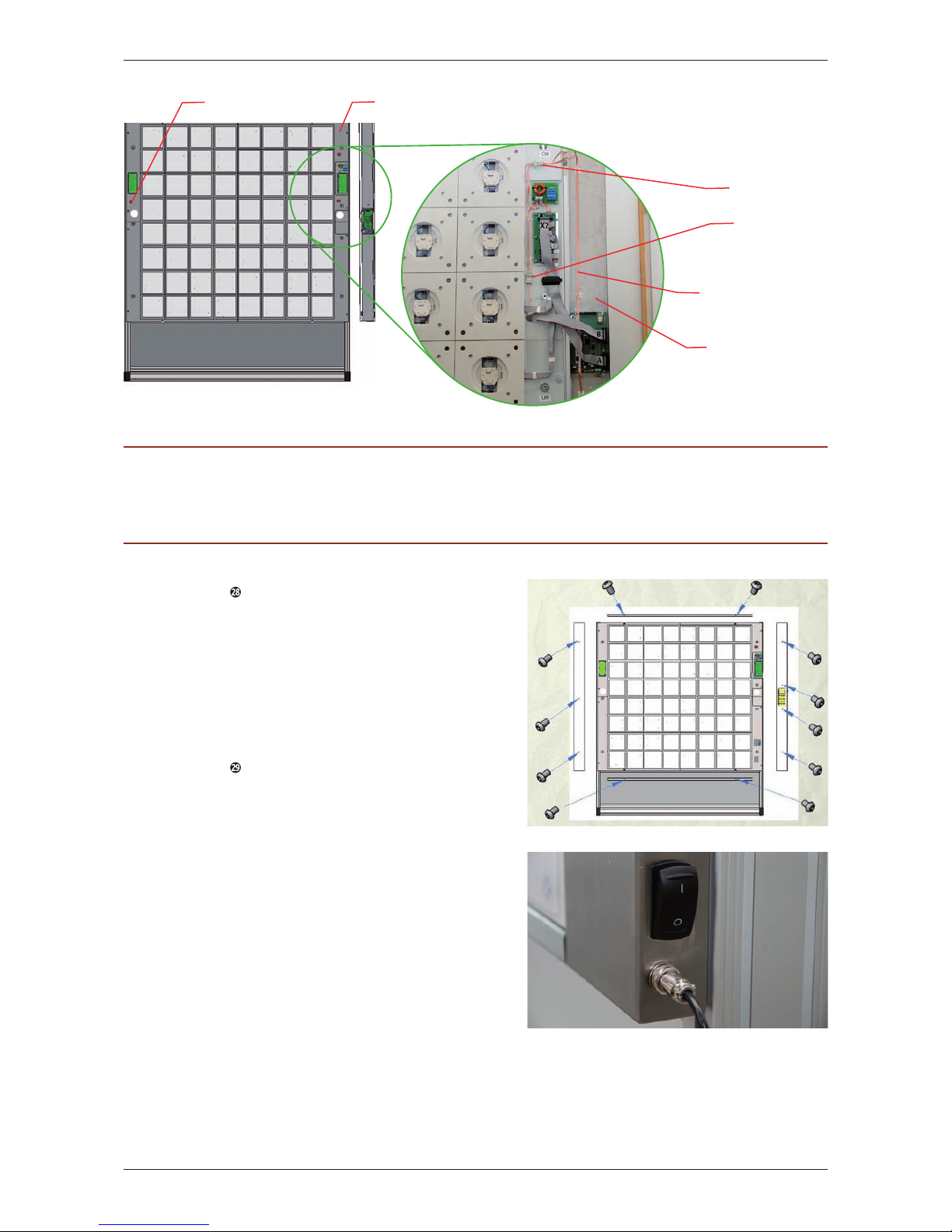
Step
28
Screw the lateral stainless steel
frame covers B1 and B2 and the upper /
lower stainless steel frame cover B3 respec-
tively to the threaded bolts attached to
the basic modules using the eleven (11)
fillister head screws M6 x 10 provided and
the corresponding Allen key (fig. 3.1-37).
Please remove the protection film before you
assemble the frame cover.
Step 29 Putting into operation: Plug the
24V barrel connector of the provided adapter
C3 into the 24V jack of the twall®. The jack
and the switch can be found at the right
stainless steel frame cover. Now connect the
adapter to the power supply line and plug it
into a 200V/ 10A socket and switch on the
twall® (fig. 3.1-38). All lights will flash up
for a short moment and the twall® is ready to
operate.
ATTENTION: Please keep in mind that the correct polarity has to be considered as it is mechanically coded.
Please avoid any violence. Please make sure to handle the cables very carefully. Do not pull or twist them,
especially not close to the connectors. Furthermore, please use the correct cable slots of the stainless steels
frame covers to avoid that any cables will be damaged.
fig. 3.1-37
fig. 3.1-38
Connector 1
Connector 3
Connector 2
Right side of the frame
fig. 3.1-36
Stainless steel frame
cover with control panel
Double-pole
power supply cable
Page 18
18 |D
twall®Premium64 stationary User manual | Rev. 4.0
3.2.1 Storage space requirements
The wall the device will be assembled to
must have a sufficient solidity and should be
suitable to use the provided dowels. Plaster-
board walls have to be covered at least twice.
The safe fastening of the device should be
checked on a regular basis (fig. 3.2-1 and
3.2-2).
In order to assemble the twall
®
, you will
require at least 2 individuals and the following
tools:
Allen keys (included in scope of delivery)
Stepladder
Spirit level
Measuring tape
Hammer drill
Drill bit (size 12 mm | 0.47 inch)
Wrench (size 17 mm | 0.67 inch)
3.2.2 Assembly instructions
3.2.2.1 Assembling the aluminium frame
I. Mounting the frame profiles:
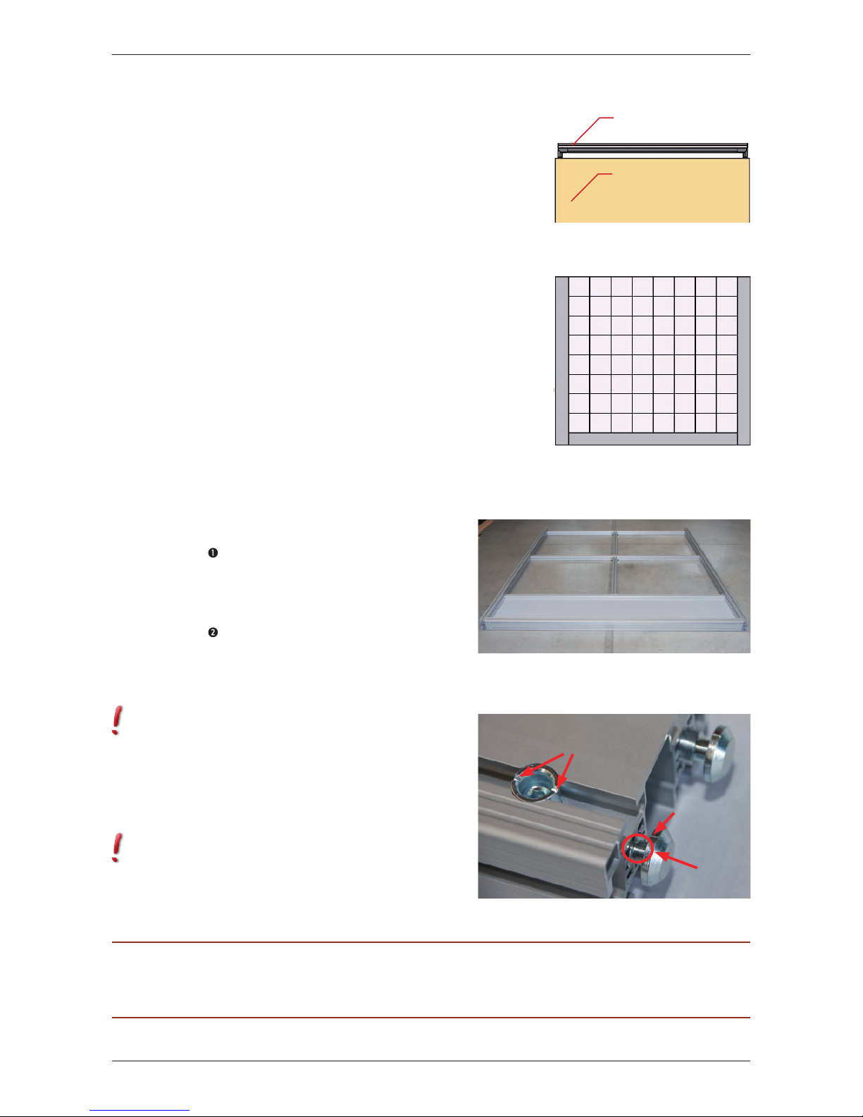
Step 1 Please remove the packaging
material. You can use it as a pad during the
assemby to avoid that the components are
scratched or damaged.
Step 2 Before you start putting together
the aluminium frame A2 (fig. 3.2-3) please
attach the eight (8) profile connectors to the
provided positions at the long frame profiles
A2c first.
In order to fasten the profile connectors, the
chamfering should point towards the cross
piece which is indicated by the mark at the
anchor (3.1-2, assembly principle of the
profile connectors). The set screw will be
slightly screwed into the cross piece with the
corresponding Allen key. The anchor will be
drawn into the profile automatically.
It is important that you can still see the neck
of the anchor (fig. 3.2-4). to be able to insert
it into the lead channels at a later point. It
might be the case that you need to push the
anchor slightly against the cross piece while
screwing it in.
PLEASE NOTE: In order to assemble the aluminium frame, place the construction on the floor. The side the
basic modules will be mounted to at a later point (side of the training area) should face the floor. Therefore, the cross pieces of the profile connectors should point upwards.
fig. 3.2-1
3m
Training area
Gestellf uß
twall
®
fig. 3.2-3
fig. 3.2-2
User´s View
fig. 3.2-4
Anchor neck
Mark at the
anchor
Mark at the
cross piece
3.2 Stationary installation of the twall®Premium64
Page 19
D| 19
twall®Premium64 stationary User manual | Rev. 4.0
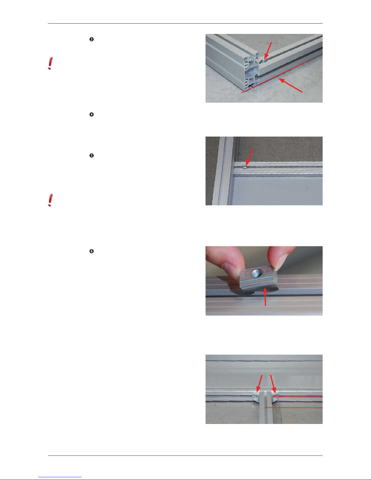
Step 3 Insert a long frame profile A2c
into the lower lead channel (towards the floor)
between the side supports A2a.
The ends of the frame profile and the side
supports have to be on the same level and
need to be flush-mounted (fig. 3.2-5). The
cross pieces of the profile connectors should
point upwards (towards you). Now tighten
the profile connectors with the corresponding
Allen key (ca. 25Nm).
Step 4 Shove the shield A2b into the
lower lead channel between the side supports.
The shield (8 mm | 0.32 inch) should click
exactly into the lead channel of the long frame
profils A2c which you have just assembled.
Step 5 Then insert another long frame
profile A2c into the lower lead channel
between the side supports and move it
towards the shield which should click exactly
into the lead channel of the frame profile (fig
3.2-6).
The cross pieces of the profile connectors
should point upwards (towards you). Please
tighten the profile connectors (ca. 25Nm).
II. Attaching the profile angles to the
frame profiles:
Step 6 In order to attach the profile
angles A2e, you will need sixteen (16) fillister
head screws with flange M6x14 (2 per
angle) and sixteen (16) T-nuts M6. Measure
the long frame profile A2c which you have
just mounted to the shield. There are 930
mm | 36.61 inch from to inner edge of the
side supports to the middle of the screws
the profile angles will be screwed on with.
Now place two (2) T-nuts in the lateral lead
channel of the long frame profile (the shield
just clicked into the lead channel at the other
side of the frame profile). Insert the T-nuts by
half-twisting them into the lead channels with
the spring ahead and align them appropriately
(fig. 3.2-7).
Now insert two (2) T-nuts into the lead
channels of the short frame profile A2d, 1 x
at the bottom left and 1 x at the bottom right.
There are 967 mm | 38.07 inch from the inner
edge of the side supports to the middle of
the lead channel. Place the short frame profile
A2d in the middle of the long frame profile
A2c and attach the profile angles A2e, one to
each side using the fillister head screws with
flange (fig. 3.2-8). Tighten it properly with
the corresponding Allen key.
Abb. 3.2-7
fig. 3.2-5
T-nut
fig. 3.2-6
fig. 3.2-8
Angle
930 mm
967 mm
Shield
Page 20
20 |D
twall®Premium64 stationary User manual | Rev. 4.0
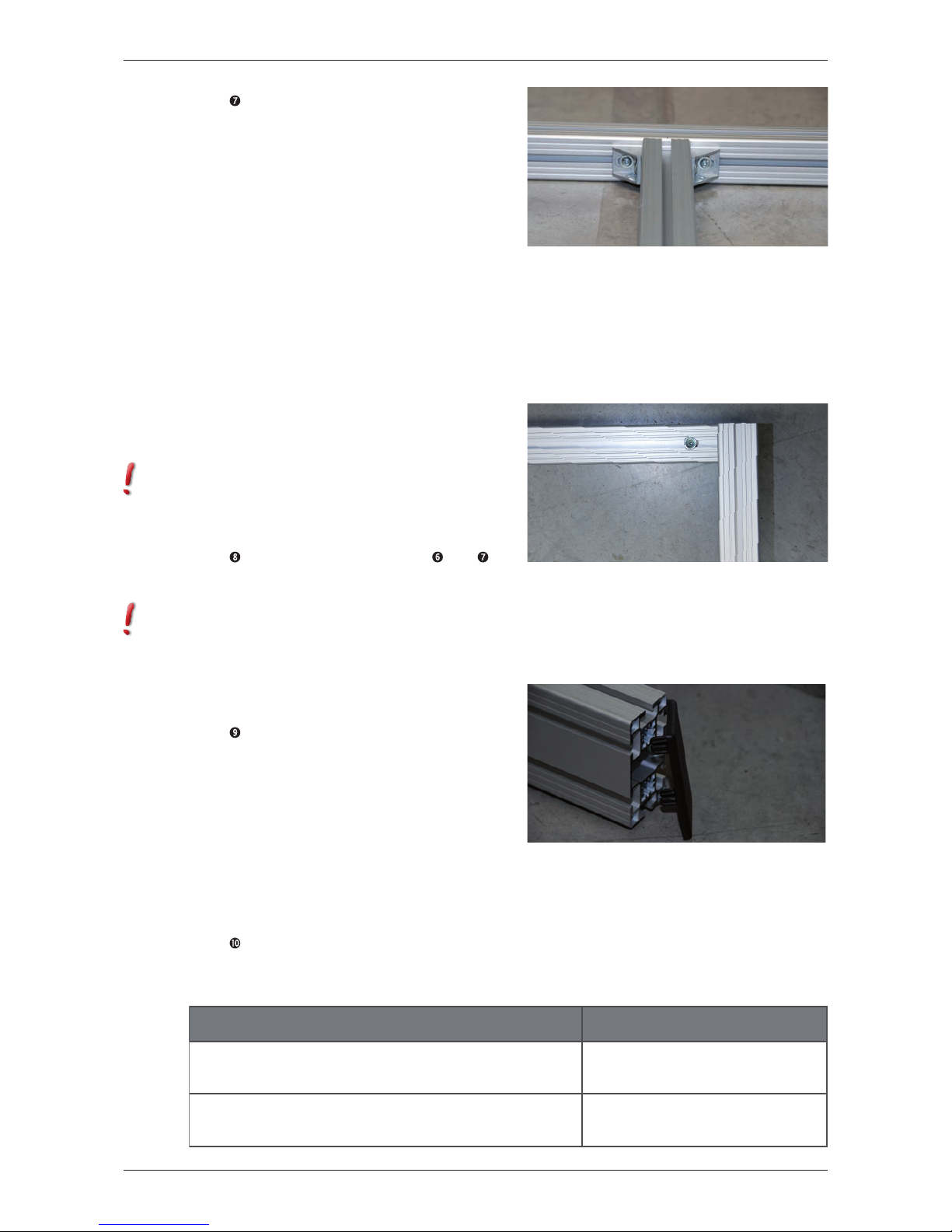
Step 7 Insert two (2) T-nuts into the
just assembled short frame profile again,
this time 1 x at the top left and 1 x at the
top right. Afterwards shove the long frame
profile A2c with the pre-assembled PVC
installation channel into the lower lead
channel between the side supports, move it
until it seats on the short frame profile. The
PVC installation channel should point upwards
(towards you). Now insert two (2) T-nuts into
the leading channel of the long frame profile
and align them as follows:
From each side measure a distance of 930
mm | 36.61 inch from the inner edge of the
side supports to the middle of the screws the
profile angles will be screwed on with. Attach
two (2) profile angles A2e to the long and the
short frame profiles again (fig. 3.2-9). Afterwards tighten the profile connectors of the
long frame profile A2c with a corresponding
Allen key (ca. 25Nm).
Please pay attention to a horizontal alignment
of the frame profile so that a correct
placement of the basic modules is ensured
(spirit level).
Step 8 Please go back to step 6 and 7
and repeat the procedure with the remaining
frame profiles A2c and A2d.
Please make sure that the ends of the last
frame profile A2c and the side supports
A2a are on the same level and will be flush-
mounted (fig. 3.2-10). Also, please check
again if you have strongly tightened all the
profile connectors (ca. 25Nm).
Step 9 Finally, put the two (2) black
cover caps on the top ends of the side
supports A2a (fig. 3.2-11) and press the
four (4) grey PVC combination profiles
into the outward lead channels of the side
supports (above the cross pieces of the profile
connectors, 2 x at the right side and 2 x at the
left side).
III. Attaching the angles for wall
fastening:
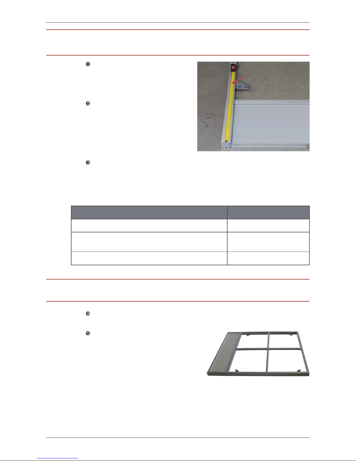
Step 10 In order to attach the angles
A2f to the side supports (fig. 3.2-12), please
take the following measurements:
Distances: twall®Premium64 stationary
From the floor to the lower edge of the lower angles
(close to the shield):
635 mm | 25 inch
From the lower edge of the lower angles to the
upper edge of the upper angle (close to the cover caps): 1415 mm | 55.71 inch
fig. 3.2-11
fig. 3.2-9
fig. 3.2-10
Page 21
D| 21
twall®Premium64 stationary User manual | Rev. 4.0
Step 11 Insert eight (8) T-nuts M8 into
the upper lead channels at the inside of the
side supports and align them according to
the measurements taken (4 T-nuts per side of
which 2 are per measurement).
Step 12 Now mount the angles A2f
to the upper lead channels at the inside of
the side supports using two (2) Verbus-Rippscrews M8x20 per angles (fig. 3.2-12).
Please tighten the screws appropriately (ca. 25
Nm).
IV. Setting up the aluminium frame:
Step 13 To be able to assemble the
aluminium frame you have to prepare drill
holes in the wall the device will be installed to.
You will require a hammer drill, a drill bit (size
12 mm | 0.47 inch) and protective work
equipment:
Distances on the wall twall®Premium64 stationary
From the floor to the middle of the lower drill hole: 660 mm | 25.98 inch
From the middle of the lower drill hole to the middle of
the upper drill hole:
1365 mm | 53.74 inch
The horizontal distance from hole middle to hole middle: 1883 mm | 74.13 inch
Step 14 Place the provided plastic dowels
10x70 in the drill holes at the wall.
Step 15 Lift the aluminium frame A2
(fig. 3.2-13) at the side where the cover
caps are located and set it up. The lower part
should be placed against the wall. Now mount
the aluminium frame to the wall by screwing
the four (4) hexagon head wood screws
10x70 into the pre-assembled plastic dowels
and tighten them properly using the wrench
(size 17 mm | 0.67 inch).
PLEASE NOTE: Basically, the height of the angles can vary especially if there any obstacles in the wall the
device will be assembled to such as trusses or pipelines.
PLEASE NOTE: Plasterboard walls have to be covered at least twice. The safe fastening of the device should
be checked on a regular basis.
fig. 3.2-13
fig. 3.2-12
Angle for mounting
on the wall
Page 22
22 |D
twall®Premium64 mobile / stationary User manual | Rev. 4.0
4 Maintenance
Every sports device is constantly exposed to dust and sweat. Same applies to the twall®. During
frequent use some soil deposit may occur on the surface of the touch elements. To ensure a long
life cycle and a maintained appearance please clean the touch elements and the frame at least
once a month. In case of more frequent use we recommend twice a month. Please use a soft,
lint-free and dry cloth. In case of heavy soiling, the cloth can be used in combination with a mild
detergent or disinfectant.
ATTENTION PLEASE: Never use dissolver or gas as this may damage the touch elements.
5 Troubleshooting
Potential errors/malfunction sources
Check if a sufficient power supply is available. Please pay attention that the po-
wer supply unit is correctly connected to the twall® and the socket.
In case of interruptions, please check if enough space is provided between the sports device
and components that generate strong magnetic fields such as loudspeakers or microwaves.
Should any liquids or external items get into the inside of the twall® discon-
nect the twall® from the power supply and contact your service provider.
3.2.2.2 Assembling the basic modules
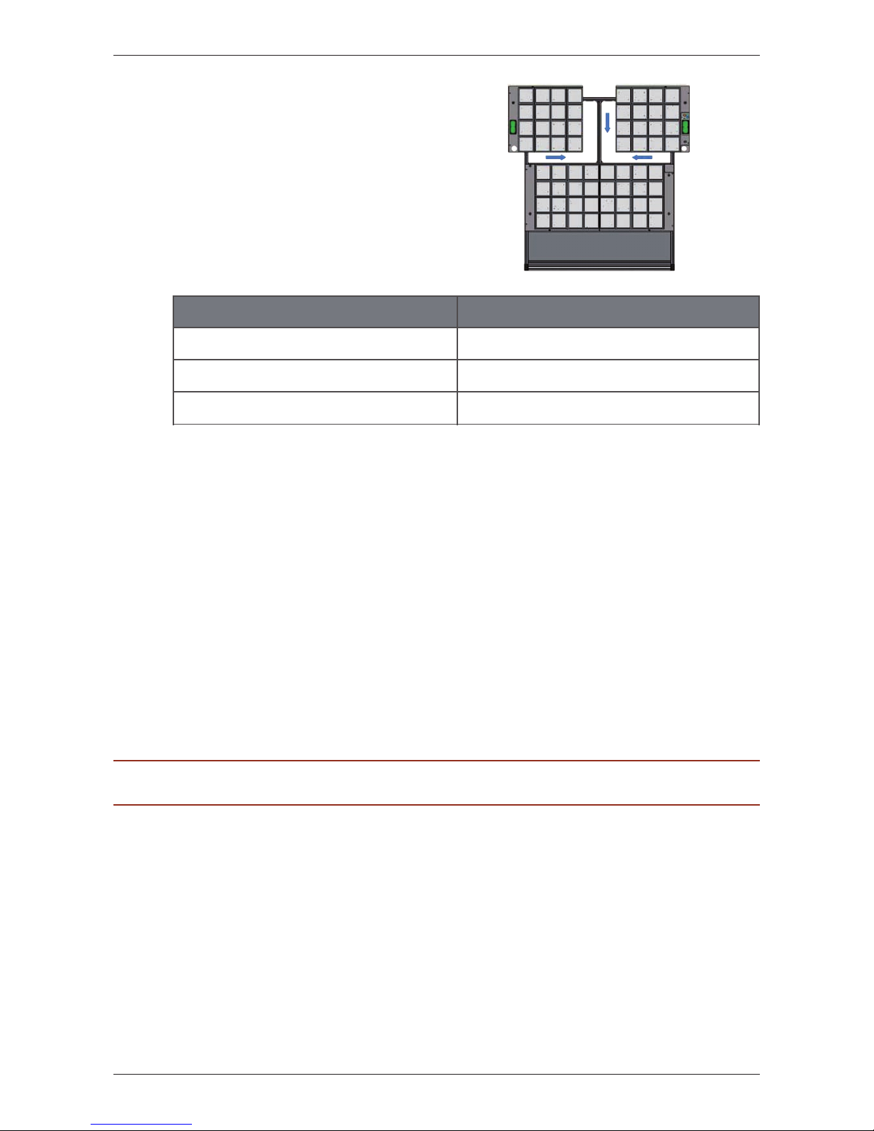
I. Setting up the basic modules:
(fig. 3.2-14)
In order to set up the basic modules,
please see the assembly instructions of the
twall®Premium64 mobile (chapter 3.1.3.3).
However, please align the T-nuts of the
stationary twall
®
as follows:
II. Connecting the basic modules to
the controll panel:
In order to connect the basic modules to
the control panel, please see the assembly
instructions of the twall
®
Premium64 mobile
(chapter 3.1.3.3).
Distances: twall®Premium64 stationary
From the floor to the middle of the 1st T-nut 570 mm | 22.44 inch
From the floor to the middle of the 2st T-nut 1230 mm | 48.43 inch
From the floor to the middle of the 3st T-nut 1480 mm | 58.27 inch
fig. 3.2-14
Page 23
D| 23
twall®Premium64 mobile / stationary User manual | Rev. 4.0
6 Technical specifications
6.1 Data sheet twall
®
Premium64 mobile and stationary
Autarkic, multicolored interactive indoor training device twall®Premium64
Integrated control panel, 10 preinstalled training programs
Graphic program surface to create favored programs
8 x 8 touch elements
Active training area in mm | inch (H x W):1760 x 1760 mm | 70 x 70 inch
Dimension of whole device
mobile in mm | inch (H x W x D): 2350 x 2030 x 1106 | 92.5 x 79.9 x 43.5
Dimension of whole device
stationar y in mm | inch (H x W x D): 2260 x 2030 x 145 x 89.0 x 79.9 x 5.7
Weight in kg | lbs (mobile) approx 231 | 509.3
Weight in kg | lbs (stationary) approx 116 | 255.7
Up to 7 fluorescent colors (red, green, blue and mixed colours)
Frame: stainless steel
Touch elements: plastic, color translucent white
Power input: 120 W
Power supply: 24 V (power supply jack and switch)
Freestanding (mobile) or wall fastening (stationary)
Maintenance intervals:
- semi-annual and according to the terms of lease respectively (mobile)
- once a year (stationary)
Guarantee 1 year
6.2 Data sheet - Accessories
Power supply line (with Euro connector)
USB cable (A/B)
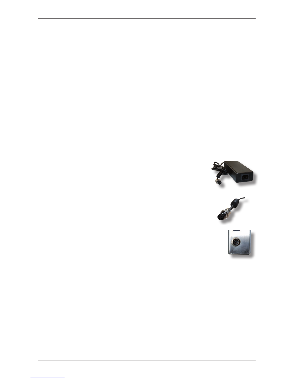
AC adapter (power supply unit) with barrel connector (fig. 6.2-1)
• AC adapter
- Primary 90-264 V AC; 47-63 Hz
- Secondary 24 V DC; 5 A
- Dimensions
(h x w x d in inch): 1.38 x 2.44 x 6.69
- Weight (in lbs): approx. 1.17
- Euro connector
• Barrel connector
(fig. 6.2-2 and fig. 6.2-3)
- Pin 1 and Pin 2 + 24 V
- Pin 3 and Pin 4 - 0 V fig. 6.2-3
fig. 6.2-1
fig. 6.2-2
Page 24
24 |D
twall®Premium64 mobile / stationary User manual | Rev. 4.0
Software documentation
7 Operating twall® using control panel
The twall® can be completely operated using the integrated control panel and neither computer
nor notebook are required. The display shows a menu which can be controlled using the four
yellow operating buttons below.
In order to navigate through the main menu and its submenus the operating buttons can be
used as follows:
Press the Arrow down - button to select the menu following the current one.
Press the Arrow up - button to select the menu shown above the current one.
ENTER leads into the selected function or menu.
MENU cancels the current menu.
Please be aware that in certain submenus different functions can be assigned to the operating
buttons.
7.1 Executing twall® programs
To execute a twall® program using the menu, select the menu item “Programs” in the main
menu and confirm with [ENTER]. This will lead you into the submenu “Programs”. All programs
installed on the twall® will be displayed. Select the required program with the arrow keys and
confirm with [ENTER] to start the program. The status of the program will now be displayed.
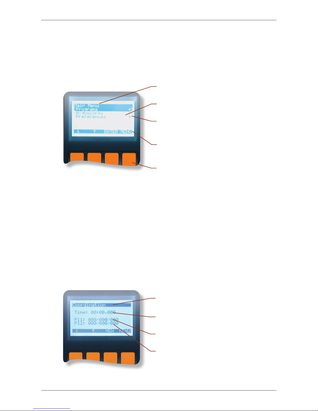
The top row shows the menu name.
The first row displays the menus functions that
can be controlled using the yellow buttons.
The right arrow indicates that the menu selected
has got further submenus.
The current menu function is highlighted in
black.
Operation buttons.
At the top the name of the selec-
ted program will be displayed.
The second row informs about
the current program time.
Status row for Player 1. The three numbers
signify: Total Targets/Scored Targets/Mistakes.
Status row for Player 2. If the program is
defined for just one player, this row will
disappear after starting the program.
Page 25
D| 25
twall®Premium64 mobile / stationary User manual | Rev. 4.0
The assignment of the operating buttons is almost identical. In the display above, you can see
that the [ENTER] button has been replaced by the NEW button that enables you to restart the
program. The next or the previous program in the list of the twall® programs can be loaded
using the arrow buttons.
The time starts counting as soon as the first pad at the twall® has been touched. The end of the
program will usually be indicated by a short flash up of all twall® touch elements.
7.2 Viewing highscores
Displaying the highscores works the same way as executing the programs. Please select the
menu item “Highscores” in the main menu using the [ENTER] button. This opens the menu
“Highscores” and a list of the installed programs will be displayed. To view the highscores of a
certain program, select the program using the arrow keys and confirm with [ENTER]. Now you
can navigate through the highscore list. This page of the screen will always show one highscore.
7.3 Settings
In the menu “Settings” you can set different parameters
of the twall®. The structure of the menu is the following:
Settings: [Display] [Audio]
1
[Information on release]
- Contrast - Volume
- Brightness - Balance
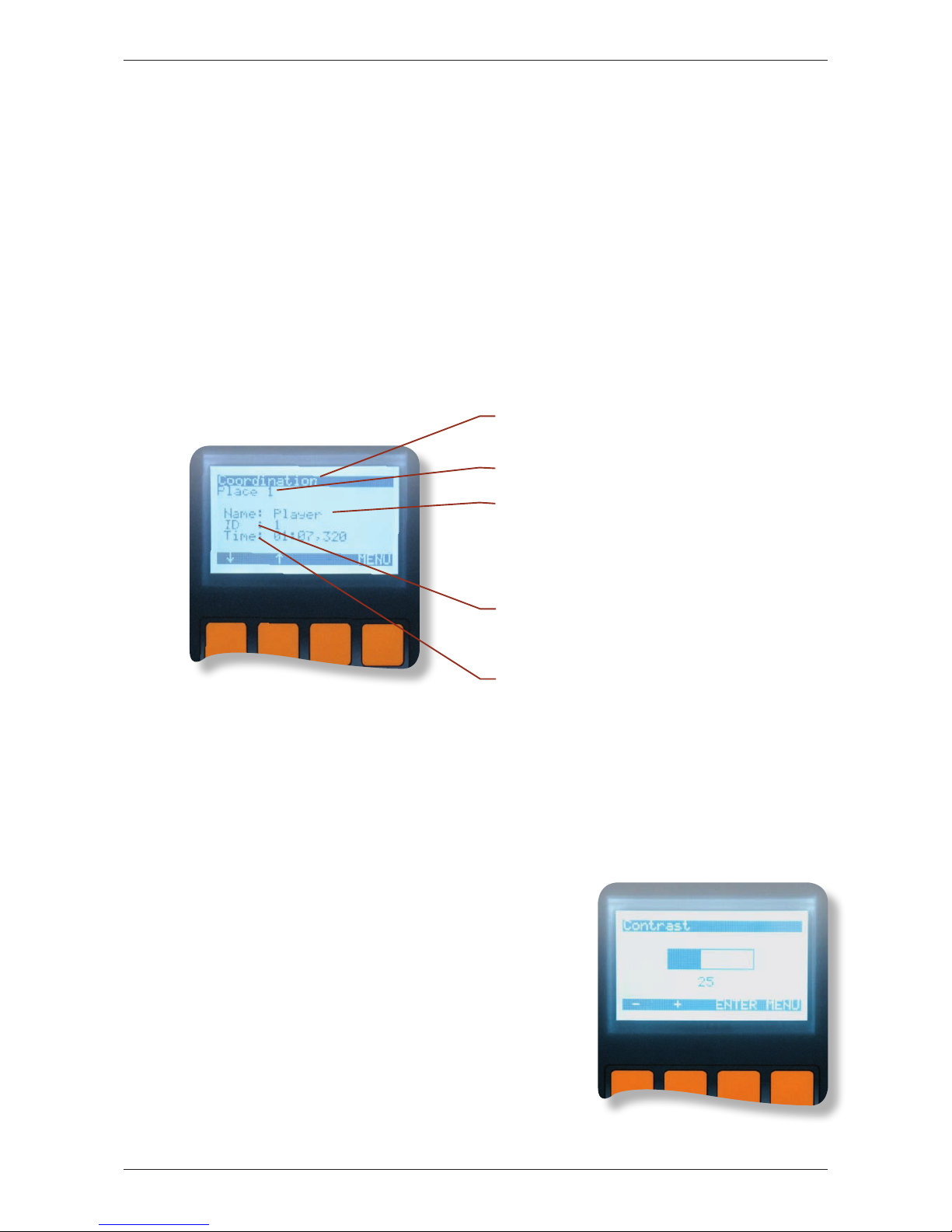
The settings can be changed using the two control keys
(+ / -). The set value will be displayed graphically inform
of a bar. To confirm the set value, press the [ENTER]
button. To cancel the process, press the [MENU] button.
The setting „information on release“ contains information
on the twall type, the hardware and software release.
That information will be required by the service team in
case of technical problems that might occur.
1
only available with twall® sound version
The top row shows the program the
highscore list is currently assigned to.
The ranking is displayed (rank 1-10).
Shows the name of the player. As it is not
possible to type in a name into the twall®
control panel, the name “Player” will be set
automatically. Further names can be entered
if the twall® is operated using the computer.
The value “ID” displays the order of the
highscore entries. The latest entry in
the list always has the highest ID.
In this row the playing time of the highs-
core entry will be displayed. The shorter the time the better the rank.
Page 26
26 |D
twall®Premium64 mobile / stationary User manual | Rev. 4.0
8 Operating twall® using computer
You can operate the twall® without a computer using the integrated control panel. However, to
be able to perform certain activities such as creating new programs a software use is required.
The following chapters provide an overview on how to install the software.
PLEASE NOTE: The twall® drivers as well as the software and firmware will be updated on a regular basis.
You can download the latest version on our website www.twall.de. Please keep the twall® serial number to
hand which you can find on the sign next to the twall® [On/Off] switch.
8.1 Connecting twall® to computer
The twall® will be connected to the computer via USB which requires an USB A/B connection
cable (included in the scope of delivery). Put the square plug into the appropriate socket at the
twall® and the flat USB plug into the computer.
When connecting the twall to the computer for the first time, it recognizes the twall as a new
device. In order to install the driver, you have to insert the software CD into the CD/DVD drive.
You will require administrator rights on your computer to be able to install the driver.
The following five steps describe the river installation using Microsoft Windows XP® and
Microsoft Vista®.
8.2 Driver installation
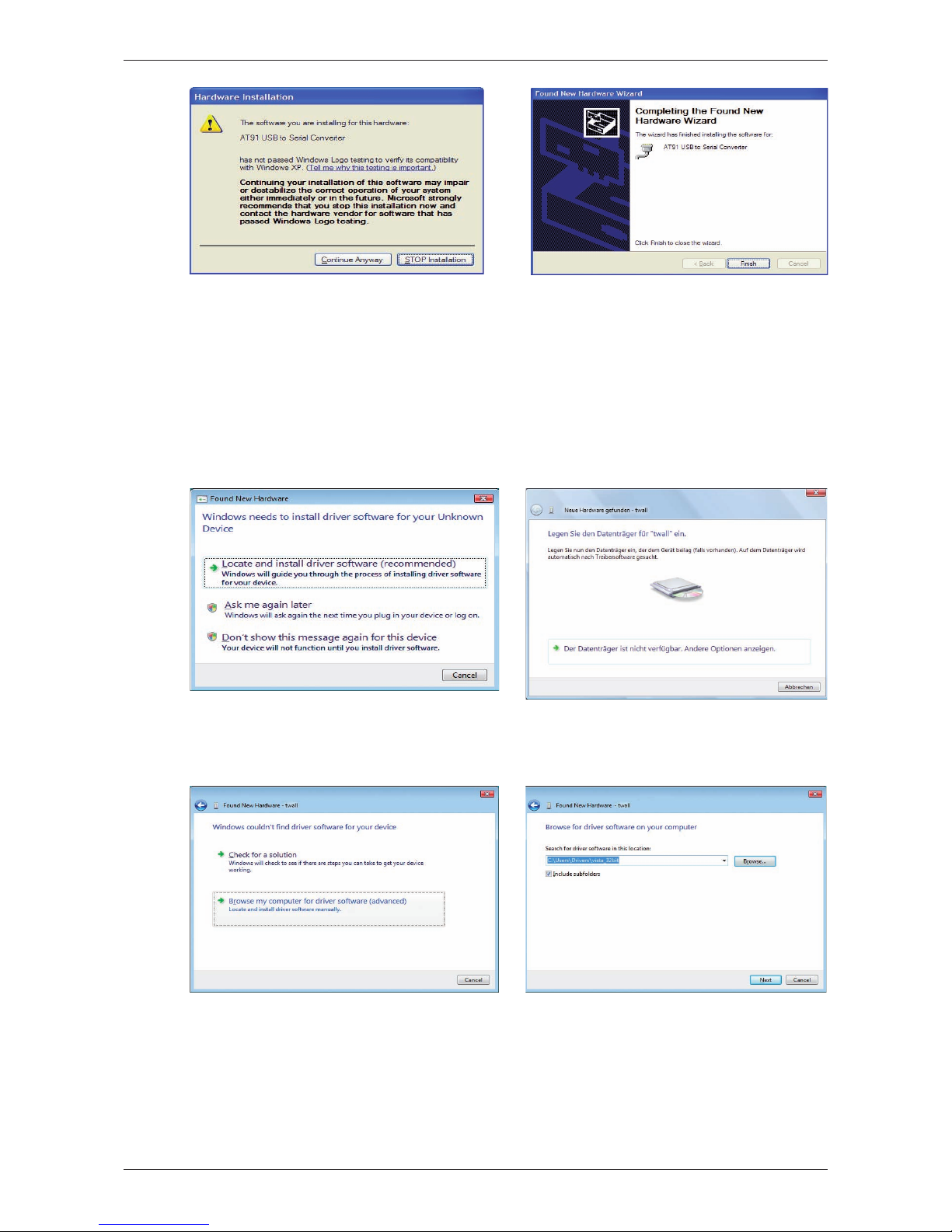
8.2.1 Installing drivers using Microsoft Windows XP®
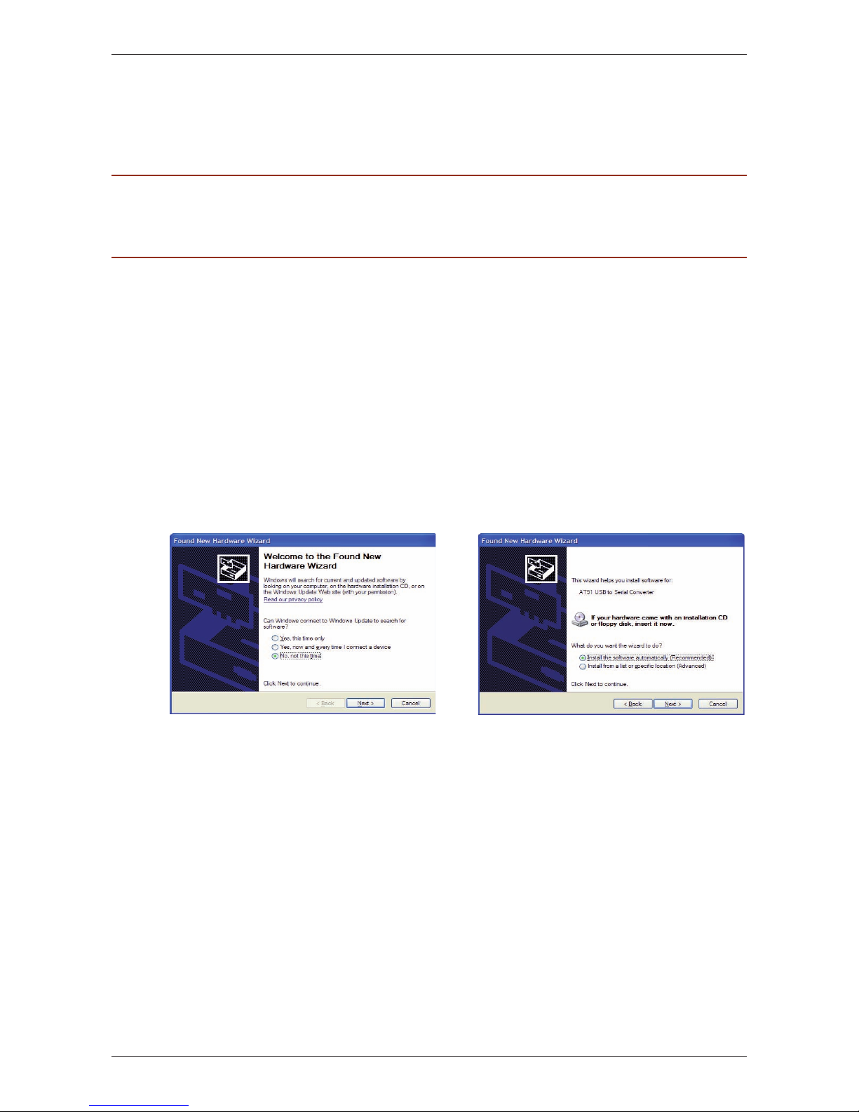
The first step of the installation is
to select “No, not this time” when
being asked if the driver should be
searched by Windows Update.
If the required driver file “usbser.sys” cannot be found on your computer, you have to define
its storage place yourself. On the CD the file is located in folder “drv\winxp” and folder “drv\
win2k” respectively. If you are using Windows XP on your computer please select the file
from the folder “winxp”. Choose the file from the folder “win2k” if you are using Windows
2000®.
Select “Install software automatically
(recommended)”. The CD will be automatically searched for the driver.
Page 27
D| 27
twall®Premium64 mobile / stationary User manual | Rev. 4.0
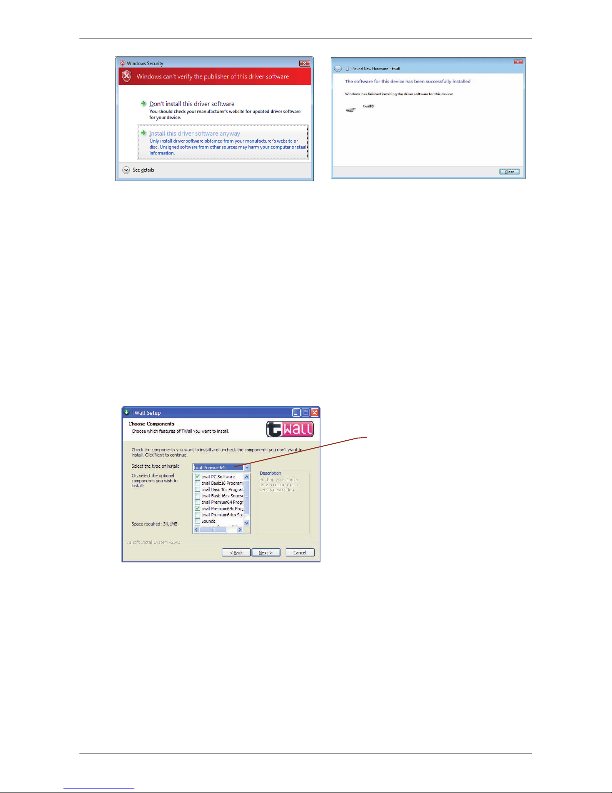
8.2.2 Installing drivers using Microsoft Windows Vista
®
Please select the first paragraph
“Locate and install driver software (recommended)”.
If this window appears, please select
the green arrow “...Andere Optionen
anzeigen“ („...Display further options”).
Please select the second green arrow
“Browse my computer for driver software”.
Please press the buttom [Browse...] and
select the directory: “Driver\vista_32bit“
on the Data-CD and click on [Next]
Select “Continue Installation” as
shown in the window above.
The installation has been
completed successfully. Now you can
install and use the twall® software.
If you connect the twall
®
to another USB slot the driver will be installed once again. This
happens automatically. However, the administrator rights are required for this process.
Page 28
28 |D
twall®Premium64 mobile / stationary User manual | Rev. 4.0
8.3 Software installation
In order to install the twall
®
software, please insert the twall
®
software CD into the CD/DVD
drive of your computer. Start the file „TwallSetup-1.0.exe” and follow the instructions on the
screen.
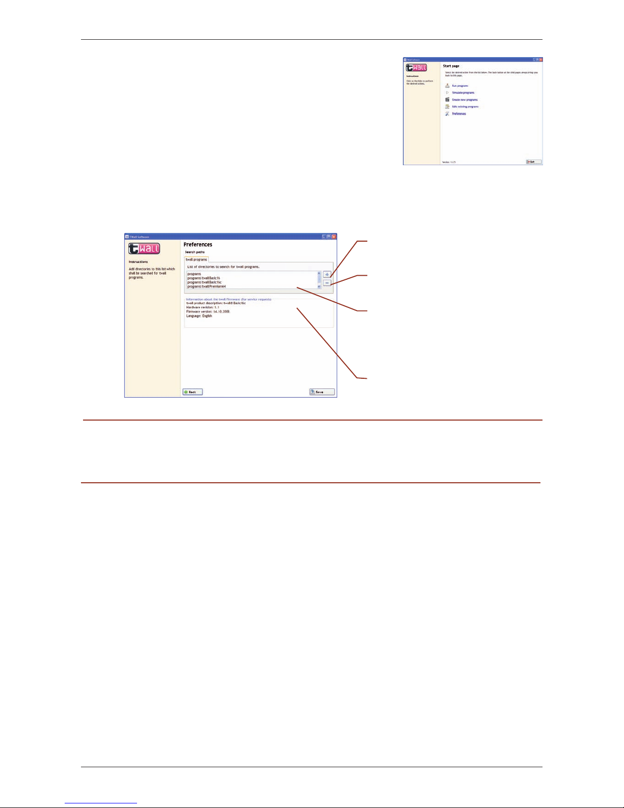
We would recommend that you select the installation type that refers to your twall®. When
selecting „Complete installation” all programs of all twall® versions will be installed. Please be
aware that a program for twall® version A might not be compatible with twall® version B.
Once the installation has been completed, you will find three links in the top menu and on the
desktop respectively. Having finished the installation, these links will start the twall® software
with a different range of functions.
twall® full functional extent (including editing of settings)
twall® (Execute programs only): Allows the execution of twall® programs at
the twall® and the simulation of twall® programs at the computer.
twall® (Execute and edit programs): As described in No 2 in-
cluding the possibility to edit twall® programs.
Such restricted software functions can be installed on computers that are used, for example, in
public areas.
Select the installation type
that refers to your twall®
version or select “Complete
installation“ to be able to
connect optional twall®
products and to create
links to your desktop.
If you connect the twall® to another USB slot, the driver will be installed once again. That
happens automatically. However, administrator rights are again necessary for this process.
Please select the second green ar-
row “Install this software anyway”.
The driver installation of the twall® has
been completed successfully. You can now
use the twall®.
Page 29
D| 29
twall®Premium64 mobile / stationary User manual | Rev. 4.0
8.4 Software description
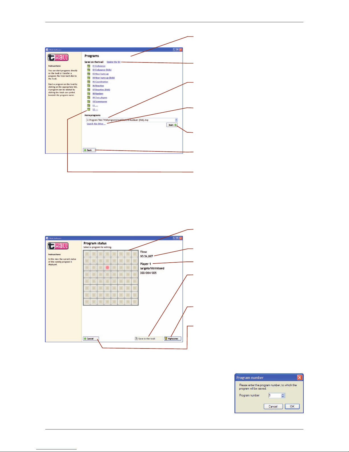
8.4.1 The welcome page
Having started the software the welcome page of the
software will be displayed. Click on the links to execute
the function requested.
8.4.2 Program settings
Having first started the twall® program for the first time
(link „TWall”), we would recommend to adjust the
program settings.
WARNING: Once the installation has been completed, the list of directories for twall® programs only contains the directories of the standard programs in the software installation folder. Please do not save any
personal programs in this directory as they will be deleted when uninstalling the software.
Therefore, we would recommend to add a directory to the list which will be kept separately from
the twall
®
software installation folder (e.g. a new directory in “My Documents”) and where you
can save your own programs.
Once all settings have been adjusted, click on the [Save] button to save the changes.
8.4.3 Executing twall® programs
Using the function „programs”, you can
• execute twall
®
programs that are installed on the twall
®
• transfer twall® programs from the hard disk to the twall® and execute them.
• save loaded twall® programs
• view highscores for twall® programes
Add a new directory to the
list using the button (+).
Delete the selected directory entry
from the list using the button (-).
This is the list of directories where
you can search for twall® programs.
In these directories it will be searched
for twall® programs to fill the program
selection boxes in the twall® software.
This box will display information
about the connected twall® .
Page 30
30 |D
twall®Premium64 mobile / stationary User manual | Rev. 4.0
8.4.3.1 Saving programs to twall®
When clicking on “Save on the twall®“, a
dialog box appears. Here you have to enter
the program number you wish the program
to be saved under. The number matches
the program number in the list of programs
located on the twall®.
Has a program been loaded, the software switches to the status display automatically. The
status of the program (elapsed time, score etc.) will be displayed. Here you can save the loaded
program to the twall®.
This field represents the current view of
the twall®.
Current playing time will be displayed.
This is the status display for Player 1.
The currently loaded program can be
saved to the twall® using this button.
This is only possible for programs transferred from the hard disk.
By using this button, the highscores of
the program will be displayed.
This button stops the execution of the
loaded program. The software switches
back to the “program” page if you click
the button a second time.
This is the list of programs located on
the twall®. Start a program by clicking
on the appropriate link.
Refresh the list of programs on the
twall® with this button.
The choice box shows all twall®
programs that could be found in
the folders searched through.
By using this link, you can add a single
file to the list which was not found in
one of the folders searched through.
Click on this button to send the selected
program to the twall® in order to start it.
Clicking on the “Back” button will
lead you to the welcome page again.
Use the recycle bin to delete a selected
program.
Page 31
D| 31
twall®Premium64 mobile / stationary User manual | Rev. 4.0
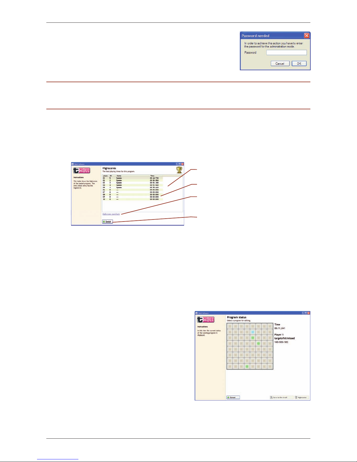
PLEASE NOTE: The password can be found on a label on the last page of the manual. Give access to people
only who are allowed to save programs to the twall®.
8.4.3.2 Highscores
By using the button “Highscores” in the status display, the list of the highscores for the currently
executed program will be loaded. The latest entry in the list is highlighted. List of high scores.
The latest entry also has the highest ID.
8.4.4 Simulating twall® programs
The program function “Simulate programs”
offers the possibility to execute twall®
programs on the computer without using the
twall® itself. This is very useful, for example,
when recently created programs have to be
tested.
Having selected the program to be simulated,
the software switches to the status display
automatically. The functions “Save to the
twall®“ and “Highscores” cannot be selected
during the simulation.
In contrast to the status display for programs
that are executed on the twall®, the here
stylized twall® is an interactive element.
During the simulation, you click on the
appropriate graphical touch pads using your
computer mouse instead of touching the push
buttons at the twall®.
The twall® would pick up the highscores if the program was started using the twall®. If the
program was transferred from the computer to the twall®, the highscores will automatically
be saved in a “highscores” file. In this case, it will be possible to enter a name when reaching
a highscore position. This highscore file containing the gained scores can be transferred to the
twall® when saving the program to the twall® at a later point.
To save a program to the twall®, a password
is required. Enter the password into the
following dialog box.
The latest entry in the list is highlighted.
Empty entries.
This link saves the highscore list as the
“highscores” file.
Back to the status display.
Page 32
32 |D
twall®Premium64 mobile / stationary User manual | Rev. 4.0
8.4.5 Creating new twall® programs
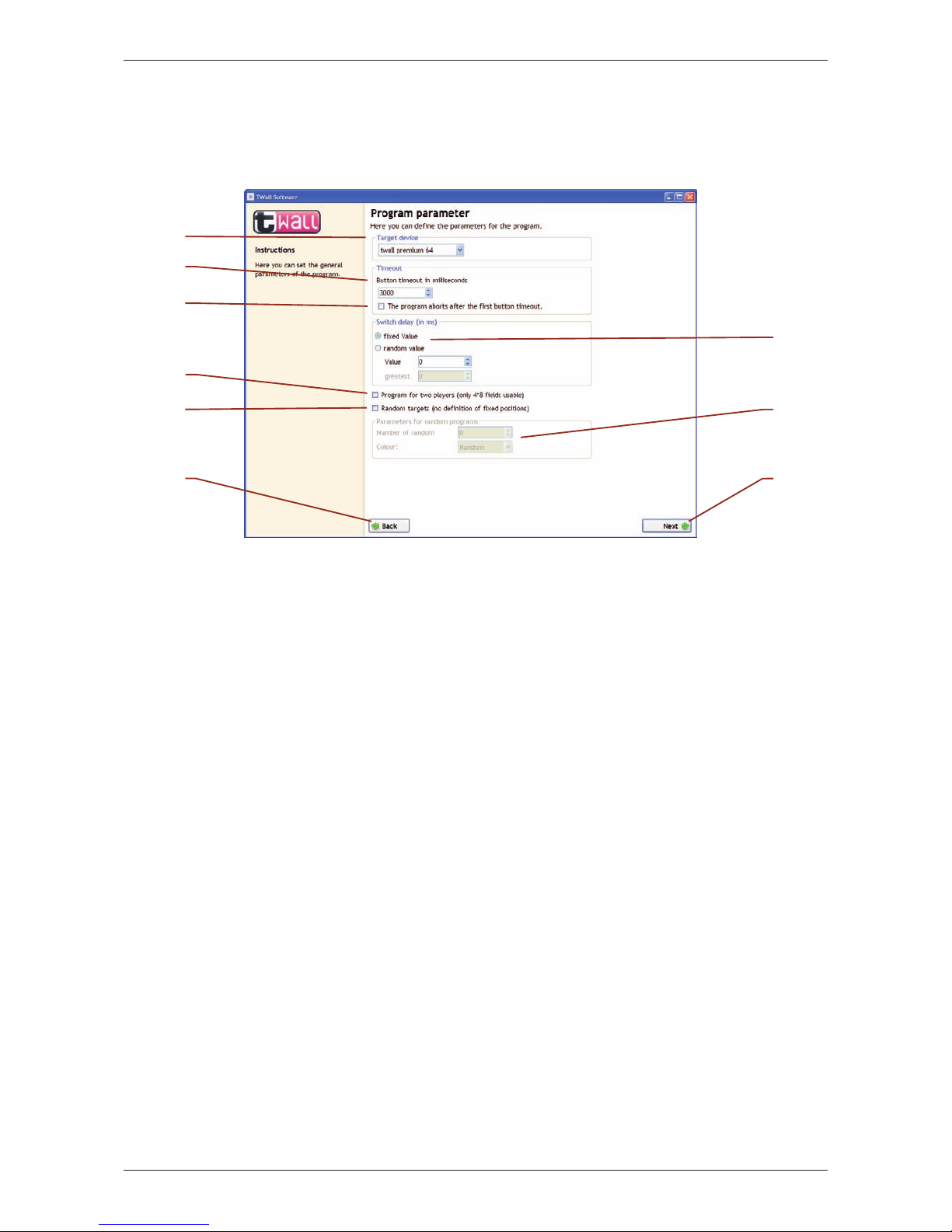
You can create new twall® programs using the program editor of the twall® software. On the
first page of the program editor you have to set the general program parameters.
In the choice box called “Target devise” you can set the twall® type the program is intended
for.
Here you can set a timeout for the touch pads. It is the maximum time that can pass
between activating (switching on) and deactivating (touching) a touch pad. The timeout will
be displayed in milliseconds between 1 and 65000. Longer timeouts are not permitted for
heating reasons. We advise that you avoid to set two identical targets when having specified
a very high timeout. Also, set the value to zero (“0”) if you do not want to use a timeout.
Once a timeout has been set and that field been activated, the program will stop the
execution as soon as the timeout runs out. Typically in this case, the twall® will rate the
current target as an error and will activate the next pad.
The switch delay is the time between the deactivation of a touch pad and the activation of
the next pad. The standard setting is zero (no delay). Select “fixed value” and enter a value
into the box called “value” to achieve a delay around that value. Select “random value” and
enter two values into the two boxes “lowest” and “highest” to get a random switch delay
within the range set (for each new target a new delay will be set).
Select this option to create a program for two players. On the following page, you will be
able to specify targets on the left side of the twall® only. The program will be identical for
the second player (right side of the twall®).
If you select this option, the following page on which individual targets can be set will be
dropped. Instead, the program will already be saved by clicking on the “Next” button. When
executing the program at the twall®, the target positions will be chosen randomly.
Enter the number of random targets and their colors here. You can either choose a regular
color or – similar to the targets – the colors can occur randomly.
Back to the home page.
To the next page of the program editor.
Page 33
D| 33
twall®Premium64 mobile / stationary User manual | Rev. 4.0
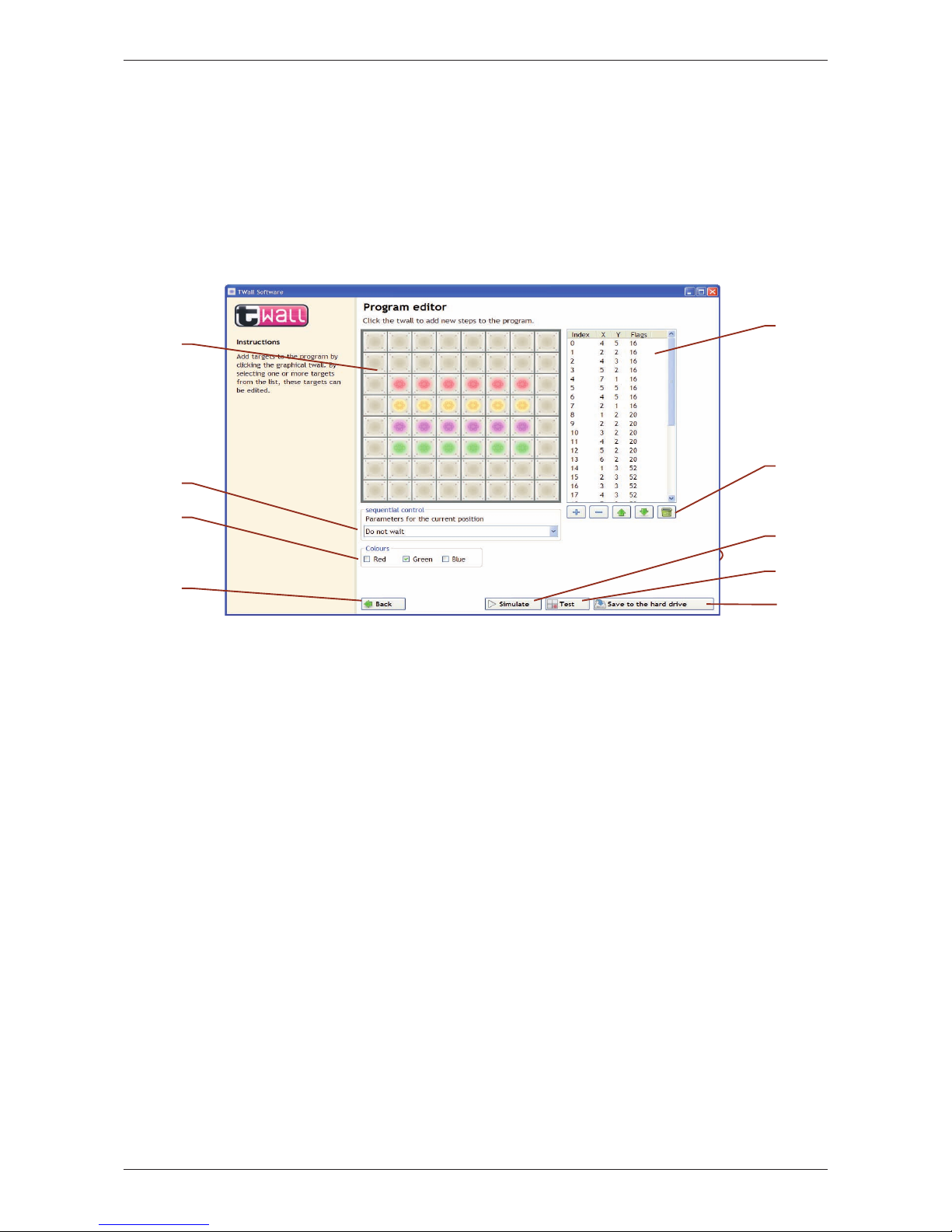
The individual targets will be set on the second page of the editor. The program editor operates
in two different modes: Create and Edit. If there is no target selected in the list of defined
targets, a new target will be added to the list by clicking on any touch pad of the graphical
twall®. The defined parameters/colors refer to the next target to be added.
If an individual target is selected from the list, you can change its position by clicking on any
touch pad of the graphical twall®. The change of parameters also refers to the selected target.
If more than one target is selected in the list, only the parameters of the selected targets can be
altered.
Add new targets to the program by clicking on the graphic pads.
Set the behaviour of the sequential control for the selected or the next target. The
parameter indicates on which occasion the sequential control is supposed should switch to
the next target.
Here you can set the color for the selected or the next target. The individual colors will be
mixed additively (red + green + blue make white).
This is the list of the defined results. The index indicates the serial number of the targets in
the program sequence, X and Y represent the horizontal and vertical target position. The
flags contain the color and parameters required for the sequential control.
Add new targets to the list using these buttons. You can also delete or rearrange the targets
or even delete the complete list.
Back to page 1 of the program editor.
The edited program can be simulated using this button. In order to do that, it has to be
saved on your hard disk first.
Transfers the program to the twall® and executes it directly. In this mode, nothing can be
saved to the twall®.
Saves the program on the hard disk.
Page 34
34 |D
twall®Premium64 mobile / stationary User manual | Rev. 4.0
The following parameters are defined for the sequential control.
Wait until exactly this pad has been touched: This is the stan-
dard setting. Once the current target has been deactivated or the timeout has run out, the program can continue with the next target.
Wait until any active pad has been touched: The program only continues with the
next target if an active (flashing up) pad has been deactivated or if the timeout has run out.
Wait until any pad has been touched: The program only continues with the next tar-
get if any pad – no matter if active or not – has been touched or the timeout has run out.
Wait until the last active pad has been touched: The program only con-
tinues with the next target if the last active (flashing up) pad has been deactivated or the timeout has run out. That mode is particularly helpful when
many pads are flashing up at the twall® and are to be deactivated before the program is finished or the program sequence can be continued.
Do not wait: Immediately after activating the pad, the program continues with
the next target. This mode is required to switch on many pads at the same time.
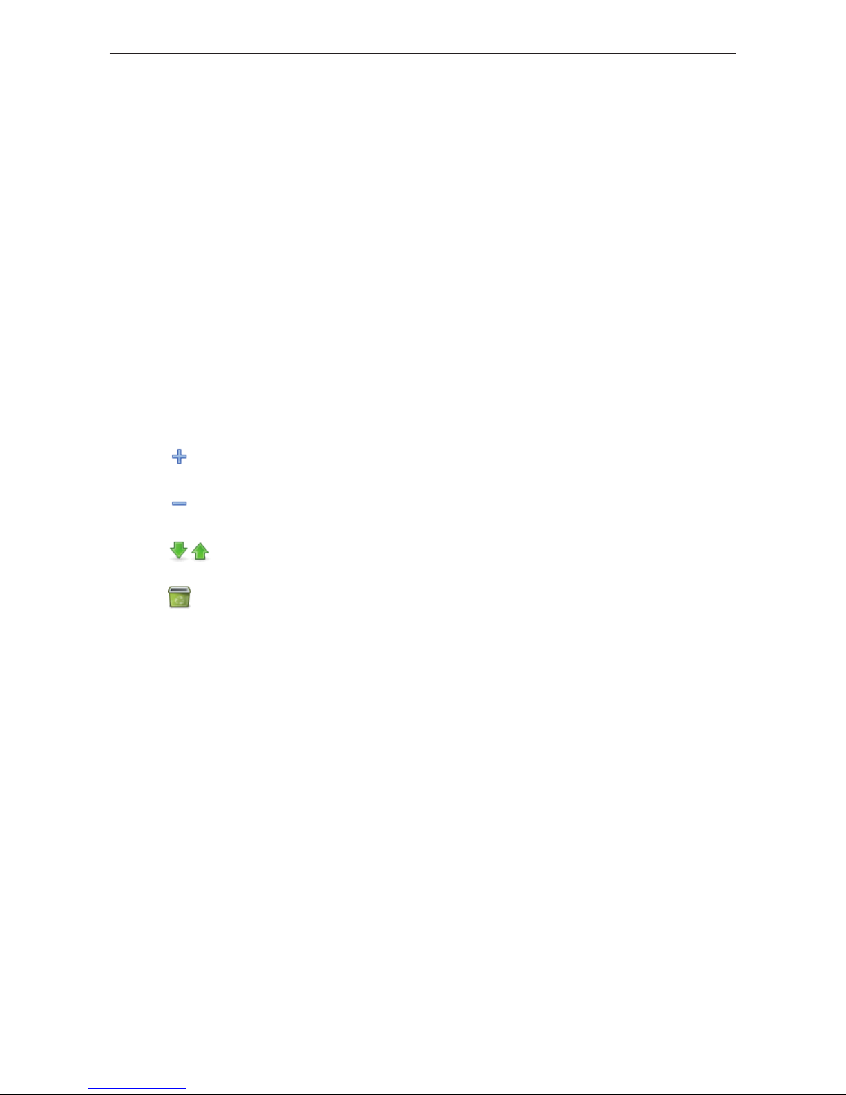
The following functions are available to edit targets in the list:
Adds a new element to the list by duplicating the currently selected element
or the last element in the list.
Removes the selected elements from the list.
These buttons move the selected element one step up or down.
Deletes the complete list.
8.4.6 Editing twall® programs
To edit twall® programs at a later point, go back to the welcome page and click on “Edit existing
programs”. Then select the program to be edited from the selection box. Otherwise, the editing
of the program works the same way as described in “create new programs”.
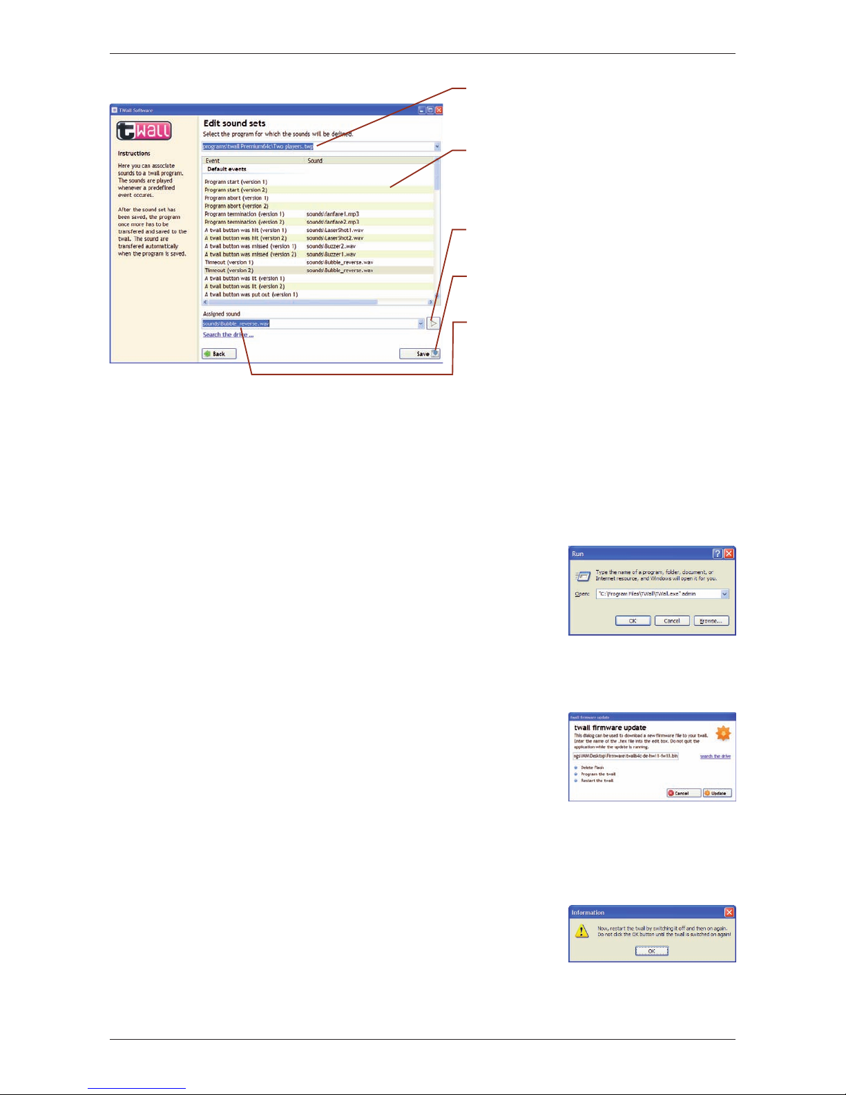
8.4.7 Editing Sound sets
Using the sound sets, sounds can be saved to certain events of a twall® program. One sound set
can be assigned to each twall® program. In order to save sounds to the twall®, the program has
to be transferred from the computer to the twall® (please see chapter 8.4.3 “Executing twall®
programs”). In that case, the sound will be transferred automatically to the SD (secure digital)
card of the twall® (the card has to be inserted into the SD card slot).
2
only available with twall® sound version
Page 35
D| 35
twall®Premium64 mobile / stationary User manual | Rev. 4.0
8.5. Firmware update
You can update the firmware of your twall® using the twall® computer software. In order to
update the firmware, the required Atmel drivers and software tools have to be installed (the
setup program for these tools starts automatically during the twall® computer software setup).
Please, always use the latest twall® computer software for firmware updates.
Please follow the steps as described below:
Connect the twall® to your computer using the USB cable.
Start the twall® computer software with the command
„admin“. The easiest way of doing that is to select “Run”
in the Windows start menu. If you have saved the software
in a different directory, you might need to change the name
of the path to the twall® computer software.
Select the link [Preferences] in the main window of the
twall® computer software. Here, you will be presented
with two buttons [Firmware update] and [Initialize twall].
Select the button [Firmware update].
Please select the new firmware file as shown in the window.
Firmware files always have the file ending .bin.
Click on the button [Update].
A new window will appear. Please enter the password for
the twall®. You will find the password on the last page of
this user manual.
During the update, you will be asked twice to restart the
twall®. This can be done by switching the twall® off and
on again.
Nach dem erfolgten Update muss die twall® Software neu
gestartet werden. Das Update ist nun abgeschlossen.
Please select the twall® program you
wish to edit the sound set for.
In that list, you can find all events
that are saved to the twall® program. The column “Sound” will
list all sounds assigned.
Select that button and you
can listen to the sound.
You can save the selected set-
tings using that button.
Once you have selected an event
out of the ones that are listed, you
can assign a sound to the event.
Page 36
36 |D
twall®Premium64 mobile / stationary User manual | Rev. 4.0
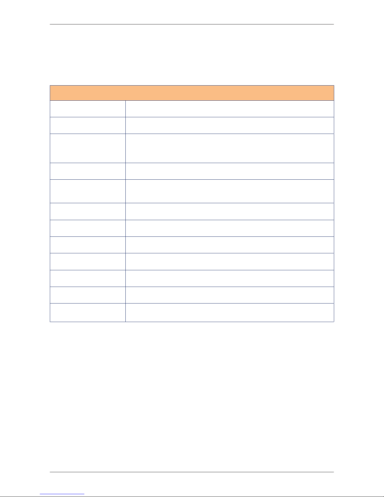
9 Standard twall® programs
Every twall® version will be delivered with 10 preinstalled programs. The programs are part of
the scope of delivery and can differ depending on the version. In the following table you will
find the standard programs and program descriptions for the different twall® versions.
twall®Premium64 - Standard programs
Endurance 300 defined targets, 5 seconds key-timeout,
Endurance (children) 300 defined targets, 5 seconds key-timeout, limited to the 4 bottom rows
Hurry up
In this game, the cyan-colored pads flash up randomly and change their
colors to green after a certain time (also randomly). The player has to try
to deactivate the pads as long as they flash up in cyan. Green keys that are
touched are considered to be failures. The game finishes once 100 cyan-
colored pads have been deactivated.
Hurry up (children) Version of „Hurry up“, limited to the 4 bottom rows
Coordination
Program to train the independence of the left and the right hand. Two
targets flash up horizontally and vertically with different delays. The left
target has to be deactivated by using the left hand, the right target by using
the right hand.
Reaction (female)
50 defined targets that flash up after a certain time (randomly/
max. 1.5 sec.), the 2 rows at the top are not used
Reaction (male)
50 defined targets that flash up after a certain time (randomly/
max. 1.5 sec.)
Screensaver The program displays an automatic animation.
2 Players 175 defined targets, 3 seconds key-timeout, program for 2 players
2 Players (children)
75 defined targets, 3 seconds key-timeout, program for 2 players, limited to
the 4 bottom rows
twall
®
test A program with column and row sequences to test the LED functionality.
touch pad test
A program to test individual touch pads. The LED lights up in white when
pressing the touch pad. However, it will light up in mixed colors if one or
more LEDs are damaged.
Page 37

D| 37
twall®Premium64 mobile / stationary User manual | Rev. 4.0
Page 38

38 |D
twall®Premium64 mobile / stationary User manual | Rev. 4.0
www.imm-gruppe.de | [email protected]
Copyright © 2009 IMM Holding GmbH
All details and information of this documet are carefully verified. However, complete correctness
cannot be guaranteed. IMM is not liable for any errors and incomplete or incorrect details.
Copying and propagation of this documentation, the use of its content as well as the use of the
product software are only allowed with written consent of IMM Holding GmbH.
Modifications due to technical progress are subject to change without notice.
Contact:
IMM Holding GmbH
Leipziger Straße 32
09648 Mittweida
Germany
web: www.imm-gruppe.de
Page 39
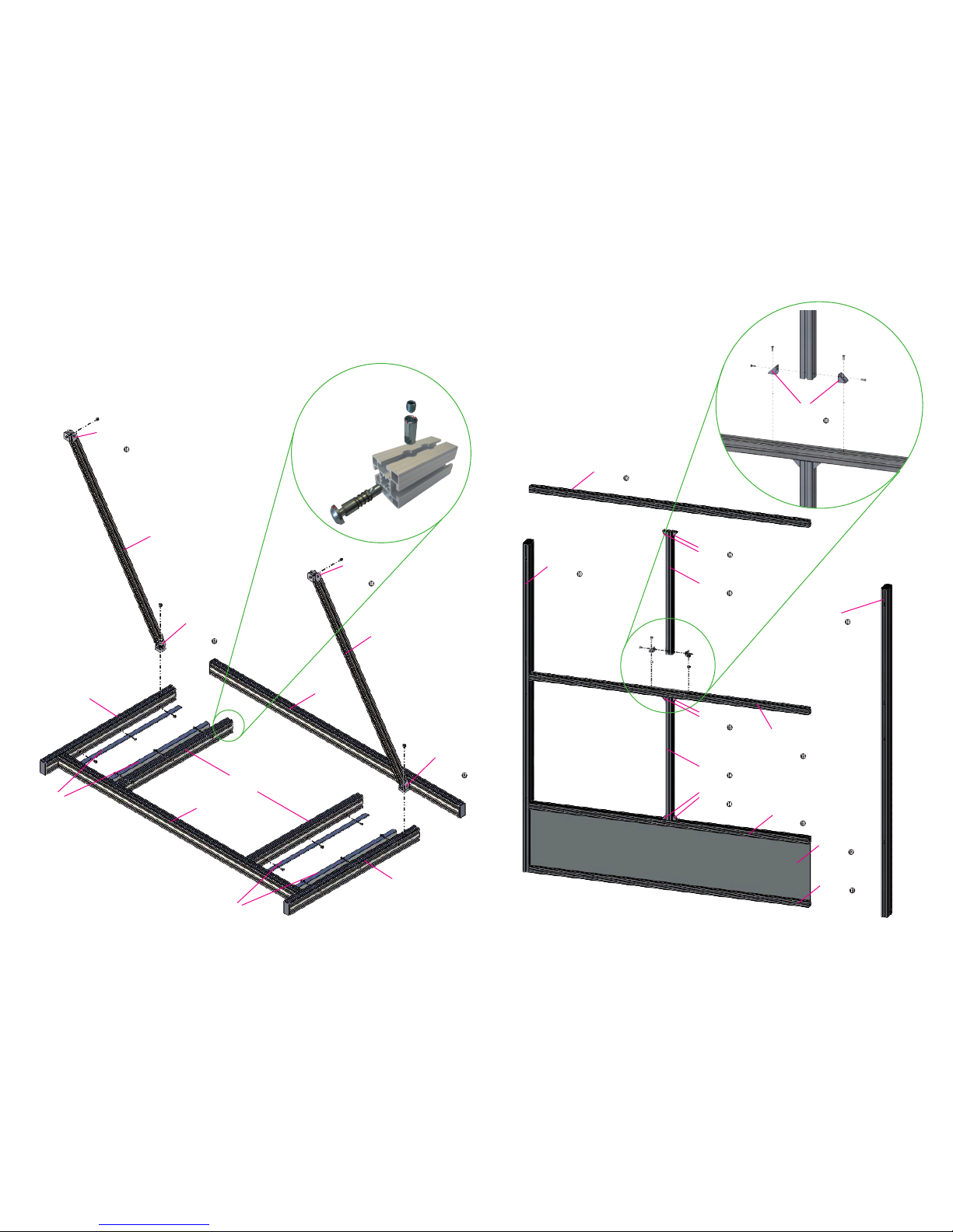
Individual assembling steps - twall®Premium64 mobile
Assembly principle
of the profile
connectors
Step
A1g
A1b
A1d
A1e
A1e
Step
Step
A1g
Step
Step
A1c
A1c
Step
Step A1a
Step
Step
Step
A1f
Step
Step
18
A1f
Step
Step
18
A1f
Step
Step
17
A1f
Step
Step
17
Assembling the frame base A1
Assembling the aluminium frame A2
A2c
Step 16
A2c
with p re-ass embled
PVC in stalla tion cha nnel
Step 15
A2e
Step 15
A2d
Step 14
A2e
Step 14
A2c
Step 13
A2c
Step 11
A2b
Step 12
A2a
Step 10
A2a
Step 10
A2e
Step 16
A2d
Step 16
A2e
Step 16
Page 40
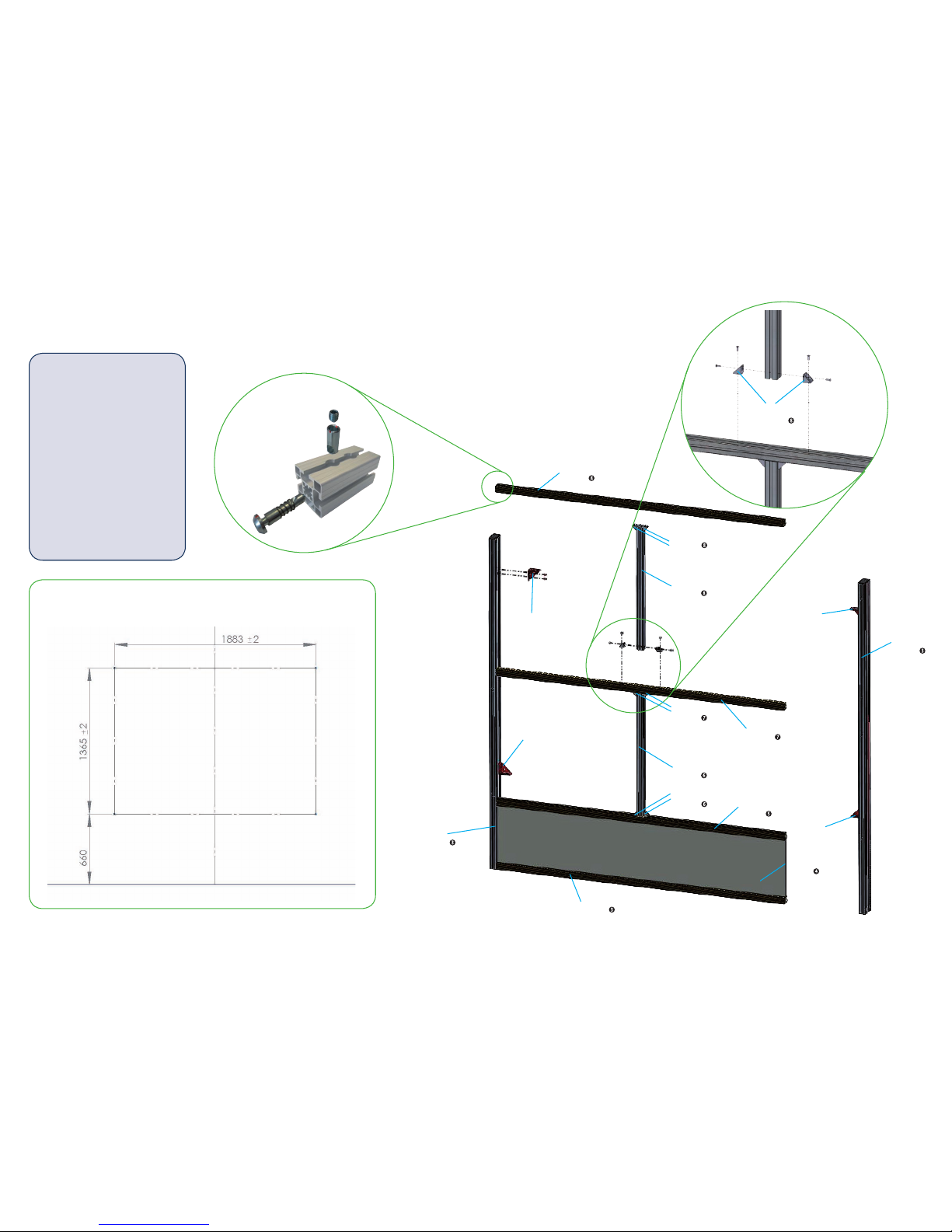
Individual assembling steps - twall®Premium64 stationary
Assembling the aluminium frame A2
A2c
Step 8
A2c
Step 7
A2e
Step 7
A2d
Step 6
A2e
Step 6 A2c
Step 5
A2c
Step 3
A2b
Step 4
A2e
Step 8
A2d
Step 8
A2e
Step 8
A2f
Step A2f
Step
A2f
Step
A2a
Step 3
Assembly principle
of the profile
connectors
Step
Distances of the drill holes for wall fastening
A2a
Step 3
A2f
Step
Floor
We hope you will find
that we have provided
a useful manual to
assemble and to operate
the twall. However,
please do not hesitate to
contact us on
[email protected] with any
suggestions you may
have to improve this
document. We appreciate
your help.
 Loading...