

™
T
W4
0
4
0
™
The Adventurer Monobander
TransWorld Antennas
INSTRUCTION MANUAL


TM
TransWorld Antennas
TW4040
TM
TW4040 Instruction Manual
1
Contents
1 Limited Warranty 3
2 Important Safety Information 4
3 Specifications
3.1 Mechanical 4
3.2 Electrical 4
3.3 VSWR Performance 5
4 Unpacking 6
5 The Components of your Antenna 7
6 Getting started
6.1 Tools needed 8
6.2 Antenna Setup 8
6.3 Connections 11
6.4 Tuning 11
7 Schematics 15
8 Contact Information 16
Due to continual product improvements, the information in this manual is subject
to change any time without notice. TransWorld Antennas will be held free from
liability, any problems arising from the use of this manual or the products
described herein.
Manual Rev V1.0

TM
TransWorld Antennas
TW4040
TM
2
TW4040 Instruction Manual
1 Limited Warranty
TransWorld Antennas warrants to the original owner of this product if purchased from an
authorized dealer or directly from TransWorld Antennas to be free from defects in
material and workmanship for a period of 12 months from date of purchase, provided
dated proof of purchase.
TransWorld Antennas agrees to repair or replace, at TransWorld Antennas’ option, any
defective product still under warranty. TransWorld Antennas will cover return shipping
only. The warranty becomes null and void if it is determined that the product was subject
to conditions beyond what the product is rated for, including, but not limited to, over
power limits, extreme environmental conditions such as flood or fire, or general misuse.
TransWorld Antennas will repair or replace, at TransWorld Antennas’ discretion, any outof-warranty TransWorld Antennas product provided all part, labor, or other repair costs
are provided by the customer, the amount of which is determined by TransWorld
Antennas.
All repairs, in warranty and out-of-warranty should be sent to TransWorld Antennas along
with a brief description of the problem and the circumstances, environmental conditions,
and equipment used at the time the problem occurred. For warranty product repairs, a
dated proof of purchase must also be supplied.
TransWorld Antennas will not be held liable, under any circumstances, for damages
resulting from the use of any TransWorld Antennas product.
TransWorld Antennas reserves the right to make changes to this product, in part or in
whole, at any time, in form, function, or manufacture, without obligation to install or incur
any costs relating to the installation of modified parts onto existing product.
This warranty gives you specific rights. Other rights may apply, which vary from state to
state.
An optional extended limited warranty purchased from TransWorld Antennas extends the
period of this warranty to 24 months or 36 months, depending on warranty product
purchased.

TM
TransWorld Antennas
TW4040
TM
TW4040 Instruction Manual
3
2 Important Safety Information
THE INSTALLATION OF THIS PRODUCT NEAR POWER
LINES IS DANGEROUS. FOLLOW THE ENCLOSED
DIRECTIONS.
1. If you are installing an antenna for the first time, for your own safety, seek
PROFESSIONAL ASSISTANCE. You r dealer can explain which mounting
method to use for the size and type antenna you are about to install.
2. Select your installation site with safety; the distance from power lines should be
at least twice the height of the antenna and mast combined. REMEMBER:
ELECTRIC POWER LINES AND PHONE LINES LOOK ALIKE. FOR YOUR
SAFETY, ASSUME THAT ANY OVERHEAD LINES CAN KILL YOU. When
installing your antenna, REMEMBER:
a. DO NOT use a metal ladder.
b. DO NOT work on a wet or windy day.
c. DO dress properly (shoes with rubber soles and heels, rubber gloves,
long sleeve shirt or jacket).
3. If the assembly starts to drop, get away and let it fall. Remember, the antenna,
the mast, the cable and the metal wires are all excellent conductors of electrical
current. Even the slightest touch of any of these parts to a power line completes
an electrical path through the antenna and the installer.
4. If any part of the antenna system should come in contact with a power line,
DON’T TOUCH IT OR TRY TO REMOVE IT YOURSELF. CALL YOUR LOCAL
POWER COMPANY. They will remove it safely.
GENERAL INSTALLATION INSTRUCTIONS FOR MAST MOUNTED ANTENNAS
1. Carefully follow the mounting instructions of the product.
2. Connect your mast at Ground by using a copper wire of minimum section 6 mm2.
3. Pay attention to the correct locking of nuts and screws.
4. If necessary (windy areas or very long masts) the use of special anti-wind rods is
recommended.
5. While your antenna is on Tx mode (transmitting) DO NOT stand nearby.
6. It is recommended to strictly respect the maximum power settled by law and
follow the instructions manual of the product.
7. Stick self-adhering “DANGER” label at eye level on your mast.

TM
TransWorld Antennas
TW4040
TM
4
TW4040 Instruction Manual
3 Specifications
Congratulations on the purchase of your TW4040 antenna! The TW4040
represents a revolutionary jump in HF antenna performance, convenience, and
reliability. The ruggedly built TW4040 was designed with ease of use in mind.
Therefore, all TW4040 antennas are pre-assembled and tuned at the time of
manufacture. With its compact three-part fold-up design, the TW4040 is ready to
go right out of the box1 for permanent or temporary installation using the supplied
quick break-down stand.
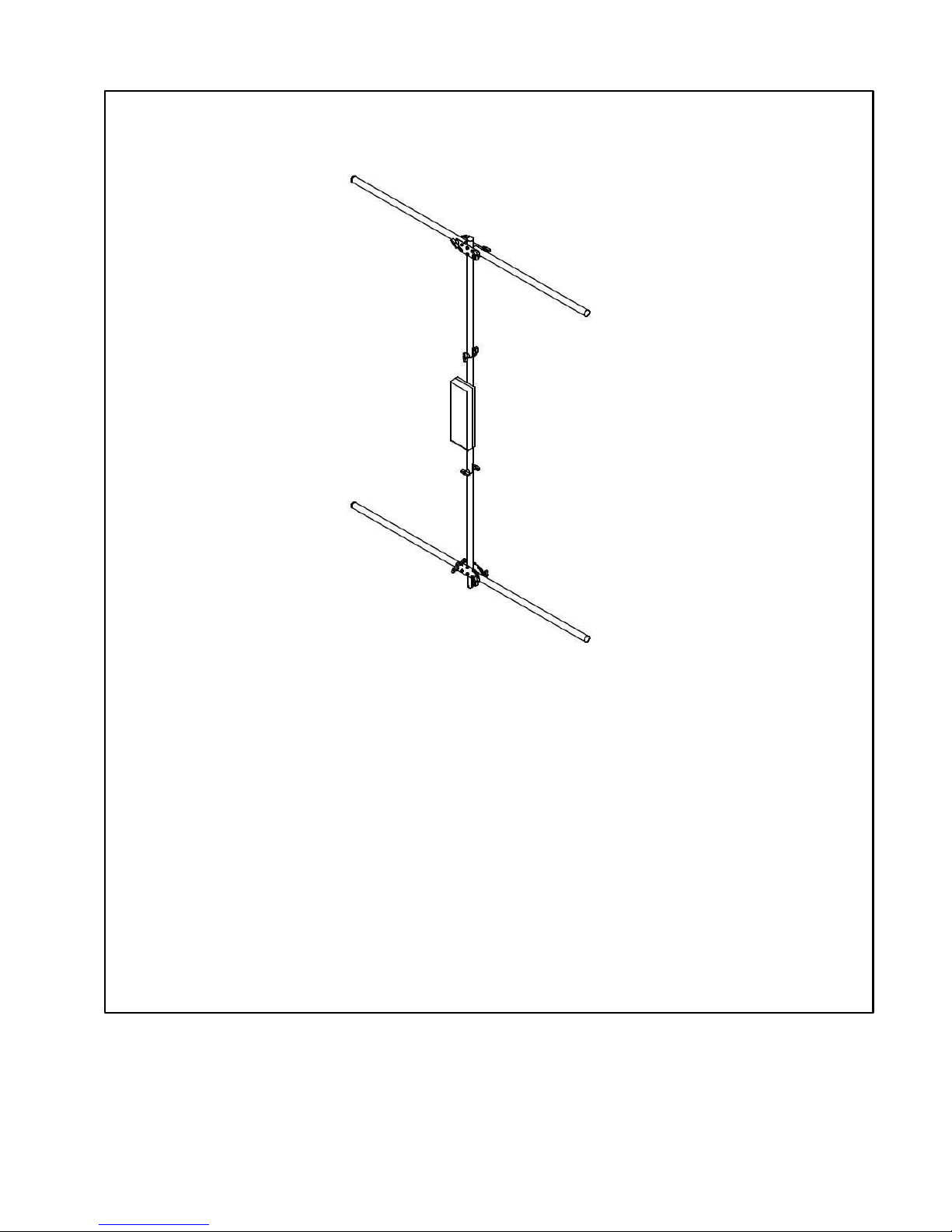
The TW4040 is a center fed vertical dipole antenna with a very low radiation
take-off angle (around 27 degrees above horizontal), allowing for very long skips
using low power on 40 meters. The TW4040 is a ground-mounted omni
directional antenna, requiring no ground radials, tower, or rotor.
3.1 Mechanical
Dimensions (folded):
Three pieces, each less than 34" long
Antenna Dimensions (after setup):
Width: 5' 3-1/2"
Height: 6' 10-1/2"
8' 3" on permanent mounting tube
Weight: Approx. 10 lbs
3.2 Electrical
Mode Maximum Power
SSB 1,200W PEP
CW 800W
RTTY 500W
AM 375W, 100% mod (full legal)
1
Tuning may be required
TM
TransWorld Antennas
TW4040
TM
TW4040 Instruction Manual
5
3 Specifications (cont.)
Antenna (cont.)
Band
1.5 : 1 Band Width
2
Typical minimum VSWR
40m
95 kHz
1.1 : 1
Directionality: Omni directional
Vertical radiation angle: 27°
Band selection: monoband only
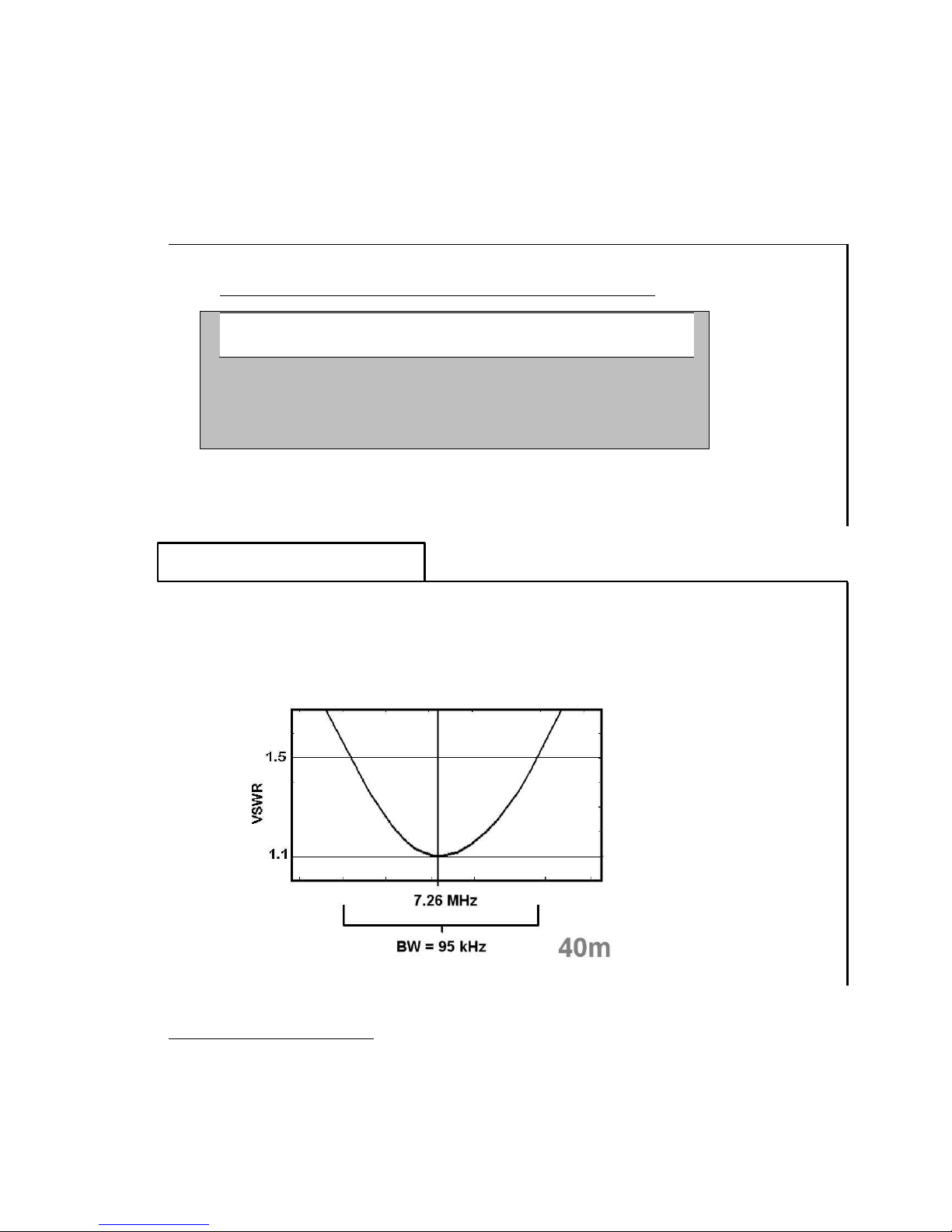
3.3 VSWR Performance
The plot below represents the VSWR performance of the antenna under the test
circumstances noted at the bottom of this page. The term “bandwidth” here
refers to the range of frequencies over which the antenna exhibits a VSWR of
1.5:1 or less.
2
Test conditions: 100 feet of quality RG8/U coax, 100W output power, antenna mounted approx. 24” above ground with
no external objects, metallic or otherwise, within 20ft radius of the antenna.

TM
TransWorld Antennas
TW4040
TM
6
TW4040 Instruction Manual
4 Unpacking
Here’s what you should find in your shipping box:
Travel Bag containing the four main pieces of the antenna structure:
o Top section
o Middle section
o Bottom section
o Permanent mounting assembly
Also included is:
o This manual
Save all packaging materials! The original shipping materials may serve as a
very handy travel box for portable applications. Also, if the antenna is returned
for warranty or money-back guarantee claims, all original packaging materials will
be required for approved shipping.

TM
TransWorld Antennas
TW4040
TM
TW4040 Instruction Manual
7
5 The Components of your Antenna
The structure of your antenna has been built in three pieces, top, middle, bottom.
The top and bottom pieces fold up for quick and easy travel. Fold-up and
assembly of the three main structure pieces is achieved using pre-installed clamp
knobs. See below for a summary of these four components.
Top Section
32.2” x 6.25” x 3.8”
Middle Section
30.13” x 7.41” x 4.88”
Bottom Section
33.75” x 6.25” x 3.8”
Permanent Mounting
Assembly
48.00” x 3.20” x 1.25”

TM
TransWorld Antennas
TW4040
TM
8
TW4040 Instruction Manual
6 Getting Started
Getting started with your new TW4040 is quick and easy. Follow these steps to
get started using your new antenna right away.
6.1 Tools Needed
A small Phillips screwdriver should be the only
tool needed for use with your TW4040, required
to open the switching array box for adjusting
tuning (page 12).
Under normal circumstances, after optional initial tuning, no tools should ever be
required for break down, transport, and setup of the TW4040.
6.2 Antenna Setup
1) Choose a location for your antenna. Ideally, the area you choose for your
antenna should be at least 7 meters (about 23 feet) from any metal structure or
other objects that could detune the antenna. However, excellent performance has
been achieved when it is placed in attics, on roofs and balconies, and in close
proximity to trees and other structures.
Danger: The antenna should not be placed anywhere near power lines, as
serious injury or death could occur. And as always, CALL BEFORE YOU DIG to
ensure you know where buried gas, water, sewer, power, and other service lines
are located.
Danger: As with any antenna installation, exposure limits should be
calculated to ensure safe operation. Visit the ARRL website
(http://www.arrl.org/news/rfsafety/) for more information on exposure limits and
calculations.
The antenna’s coax feed line should be run at a 45-degree angle down from the
structure to the ground to minimize parasitic coupling (see figure on page 11).
Failure to do so will result in higher than expected VSWR readings. Plan for this
extra footprint when choosing a location for your antenna.
2) Install Permanent Mounting Assembly. The supplied Permanent Mounting
Assembly consists of insulator rod attached to an aluminum tube using stainless
steel hardware. The assembly can be installed with or without the use of

TM
TransWorld Antennas
TW4040
TM
TW4040 Instruction Manual
9
concrete. Though concrete will provide a more secure, permanent base for your
antenna, it will be difficult to remove or re-position later. The assembly should be
inserted about 12-24” into the ground, exposing 24-36” of the assembly above
ground.
It is suggested that the antenna be tried in an area
using the permanent mounting assembly in a hole in
the ground before concreting, in case the antenna
needs to be moved later. Once you are sure of the
location for the antenna, the Permanent Mounting
Assembly can be concreted into place, if desired.
Warning: The fiberglass insulating rod is not
hammer-proof. Do not pound the Permanent
Mounting Assembly into the ground like a stake.
Permanent damage to the fiberglass insulating rod
could occur. If it is necessary to drive the assembly
into the ground, first remove the fiberglass insulating
rod using a 5/32” Allen wrench and a 7/16” socket.
Drive the aluminum permanent mounting tube into
the ground using a rubber mallet. Alternatively, a
conventional hammer can be used if a wooden board is laid over the aluminum
mounting tube before striking.
3) Assemble antenna. First, attach the bottom section to the middle section,
making sure to slide the pieces completely together. The ¼” slots on the end of
the middle section should engage completely with the stud of the clamp knob on
the end of the bottom section, as shown in step 1 below. Tighten the clamp knob
snugly.
Second, attach the middle section to the top section as shown in step 2 below.
Again, the clamp knob stud should fully engage with the slots on the end of the
top section. Tighten the clamp knob snugly.

TM
TransWorld Antennas
TW4040
TM
10
TW4040 Instruction Manual
Finally, fold the arms of the top and bottom sections out as shown in step 3. The
arms should be folded out complete ly horizontal. Firmly tighten all four clamp
knobs to ensure that the top arms do not rotate downward over time.
4) Install antenna onto the Permanent Mounting
Assembly. As shown at right, slide the bottom of
the bottom section onto the Permanent Mounting
Assembly’s insulator rod. As with assembly above,
the slots on the end of the bottom section should
fully engage with the mounting assembly’s clamp
knob stud. Firmly tighten the clamp knob.

TM
TransWorld Antennas
TW4040
TM
TW4040 Instruction Manual
11
6.3 Connections
Warning: Turn off equipment before making or removing any connections.
Failure to do so could result in equipment damage.
Coax cable. Connect your coax cable to your
radio and to the SO-239 on the TW4040’s
loading array box. It is highly recommended to
use at least 65 feet of coax on your TW4040.
For best performance, use a high quality RG-8
or RG-8X coax cable.
Final connection notes: The coax cable should
feed the antenna at a 45-degree angle as
shown in the figure at right. Failure to do so
will result in parasitic coupling and cause
higher than normal VSWR readings.
6.4 Tuning
Although your TW4040 was factory pre-tuned3, the environment in which your
antenna is placed has an effect on tuning. Some minor adjustments may be
necessary to tune the antenna to the desired center frequency for each band.
Check the tuning of the antenna using an analyzer or the SWR meter on your
transceiver before performing the tuning process. Post-factory tuning might not
be required.
Danger: Do not apply RF power to the antenna while anyone is standing
near the antenna. RF burns or electrical shock may occur, causing severe injury
or death.
3
The antenna is pre-tuned to the center of the general portion of the phone band under circumstance that
may differ from the environment of your specific installation.

TM
TransWorld Antennas
TW4040
TM
12
TW4040 Instruction Manual
Loading Array Operation. Both of the coils on each half of the loading array
are series connected. The bottom half of the loading array is effectively a mirror
image of the top half.
Equipment. The tuning process requires Voltage Standing Wave Ratio (VSWR)
measurement. These measurements can be accomplished using most any
antenna analyzer. However, these devices typically generate a very small signal
(less than 0.2W), and may show higher than expected VSWR readings. A
reading of 1.3:1 at the tuned frequency is typical at this low power. The VSWR
readings should decrease once the antenna is used with 5W of power or more.
The VSWR reading on your transceiver will likely show a lower VSWR than a
low-power antenna analyzer.
Cables. Make sure that the coax used for the tuning process is at least 65 feet
long, and that the coax is installed at a 45 degree angle as described on page
11.
Tuning. By spreading both “Coils A” and “Coils B” above, the tuned frequency
will increase. Likewise, compressing the coils will decrease the 40m tuned
frequency.
1) Preparation. To begin the tuning process, remove the loading array cover
using a small Phillips screwdriver and connect the coax cable to the loading array
box. The coax you use for the tuning process should ideally be the coax you
plan to use for the antenna during normal use. Connect the coax cable to the
device you wish to use to measure VSWR.
2) Tune. Determine to what frequency the antenna is best tuned. If you wish to
increase the tuned frequency, spread open both “Coils A” and “Coils B” on the
circuit board, as shown in the figure below.

TM
TransWorld Antennas
TW4040
TM
TW4040 Instruction Manual
13
TransWorld
Antennas
TM
Tk/lf040
Spreading coils increases tuned frequency
Coils A
0 0
0 0 0
Coils B

TW4040TM
Instruction
Manual
13


TM
TransWorld Antennas
TW4040
TM
14
TW4040 Instruction Manual
Final tuning notes
If lower bands exhibit very low VSWR, but higher bands suffer VSWR problems
(or vice-versa), the spread of the center coil can be adjusted to effect which
bands tune best. By spreading the center coil slightly, the low-frequency bands
will tune better, and by compressing the center coil, the higher-frequency bands
will tune better. But note that if the center coil is changed, the tuned center
frequencies may change and the tuning process above will have to be repeated.
If tuning proves difficult, follow this checklist to eliminate common tuning
problems:
Is your antenna placed at least 30 feet away from other objects (buildings,
people, trees, etc.)? The ends of the antenna’s arms are very sensitive to
coupling with external objects.
Is your antenna installed such that the arms are at least 24” off the ground?
The spacing between the antenna’s arms and the ground should be between 24”
and 36”.
Is your coax cable a high-quality RG-8 or RG-8X cable?
Is your coax cable long enough? At least 65 feet of coax should be used for
best results.
Is your coax installed at a 45-degree angle with respect to the antenna as in
the figure on page 11?
Are you checking the VSWR using less than five watts? Once at least five
watts is applied to the antenna, VSWR readings may improve significantly.

TM
TransWorld Antennas
TW4040
TM
TW4040 Instruction Manual
15
TM
TransWorld Antennas TW4040
7 Schematics
This page contains the schematics for the TW4040’s TW-RB-3 loading array.
TW-RB-3
Loading Array

TM
TW4040 Instruction Manual 15


TM
TransWorld Antennas
TW4040
TM
16
TW4040 Instruction Manual
8 Contact Information
If you need to contact TransWorld Antennas, just drop us an email at:
support@transworldantennas.com
Use this email address for help with installation, setup, tuning, or operation, for
product or company information, or warranty/money back guarantee claims.
Check back at our website frequently for product updates at:
www.transworldantennas.com
We can also be reached through our web-based contact system on the website.
 Loading...