

TVT Digital TD-9622E Quick Start Manual
IP Speed Dome Camera
Quick Start Guide
■ Please r ead this in structi on carefu lly for correct use of the
produc t and prese rve it for re ference p urposes .
■ All the ex amples an d picture s used here a re for reference
only.
■ There may be several technically incorrect places or printing
errors i n this manu al. The updates will be adde d into the ne w
version of this manual. The contents of this manual are subject
to chang e without n otice.
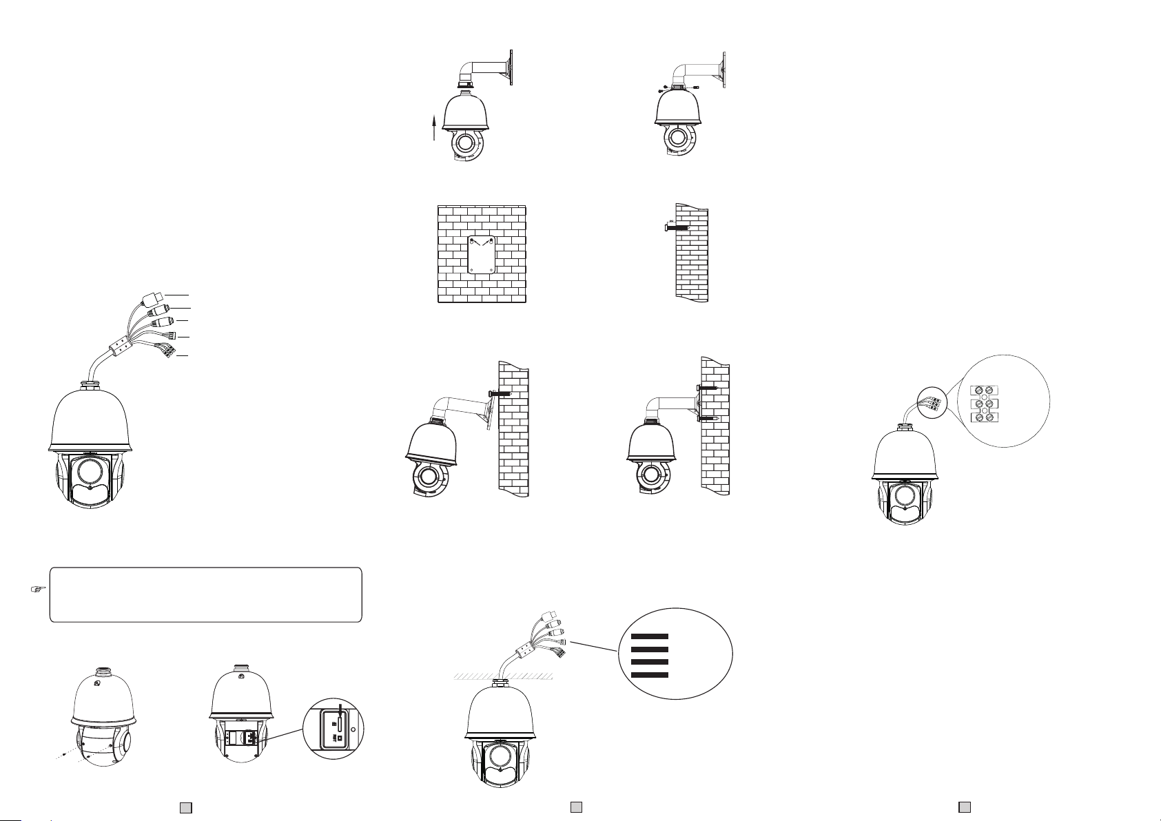
1. Interfaces and Parts
1
2
3
4
5
① LAN
② HP Audio O ut
③ MIC In
④ Alarm In/ Alarm Out
⑤ Power
2. Installation
Ple ase make sure the wall is strong enough to bear the dome
cam era’s wei ght. Ple ase make sure the camera is powered off
dur ing inst allation .
◆ Install S D Card
Insert SD card
◆ Inst all the Speed D ome
① Pull the cables through the bracket. Mount the
speed dome to the bracket.
③ Drill the screw hol es on the wall according
to the dr il l templat e. Then i ns ert the pla st ic
plugs i nt o the holes .
⑤ Connect the cables and then hang the
bracket on the wall .
3. Connections
N
Pow er
② Secure the speed dome to the bracket with
the screws.
④ Drive the two screws to the holes indicated
by the ar ro ws (left) a nd l eave 12 mm
clearance.
⑥ Fix the bracket to the wall with four
screws.
ort
t
u
ork P
w
o O
et
i
ud
A
HP
MIC I N
ALM-O PE N
ALM-C OM
ALM-G ND
ALM-I N1
Alar m Co nnectio n:
1. Alarm In put
a) There is on e indepen dent alarm in put port (A LM-IN1) a nd
one grou nding por t (ALM-GN D).
b)Alar m input(N O type): Co nnect DC5 V~DC12V volta ge
betwee n the alarm input port( ALM-IN1) and the grounding port
(ALM-GND).
c) Alarm in put(NC ty pe): Disconnect the vo ltage bet ween the
alarm input port(ALM-IN1) and the grounding port (ALM-GND).
2. Alarm Ou tput
a) Suppo rt 1CH alar m output in cluding O PEN, COM
connec tions.
b) Alarm ou tput: One p assive sw itch for user t o connect a larm
devices; the alarm output state will be auto on/off according to
your set ting.
Powe r Co nnectio n:
24V A
Earth
24V B
4. IE Network Connections
You can conn ect the IP camera thr ough LAN/ WAN ac cess.
Here tak e the IE brow ser (6.0) f or exampl e.
◆ LAN
In LAN, th ere are two w ays to acce ss. a. Access th rough
IP-Tool; b. Directly Ac cess thro ugh IE Browser
① Loosen the two screws of the dome.
② Open the cover and insert SD card.
1
● Access th e camera through IP- Tool
① Make sur e that the ca mera and th e PC are well c onnected
to the LAN .
2
3
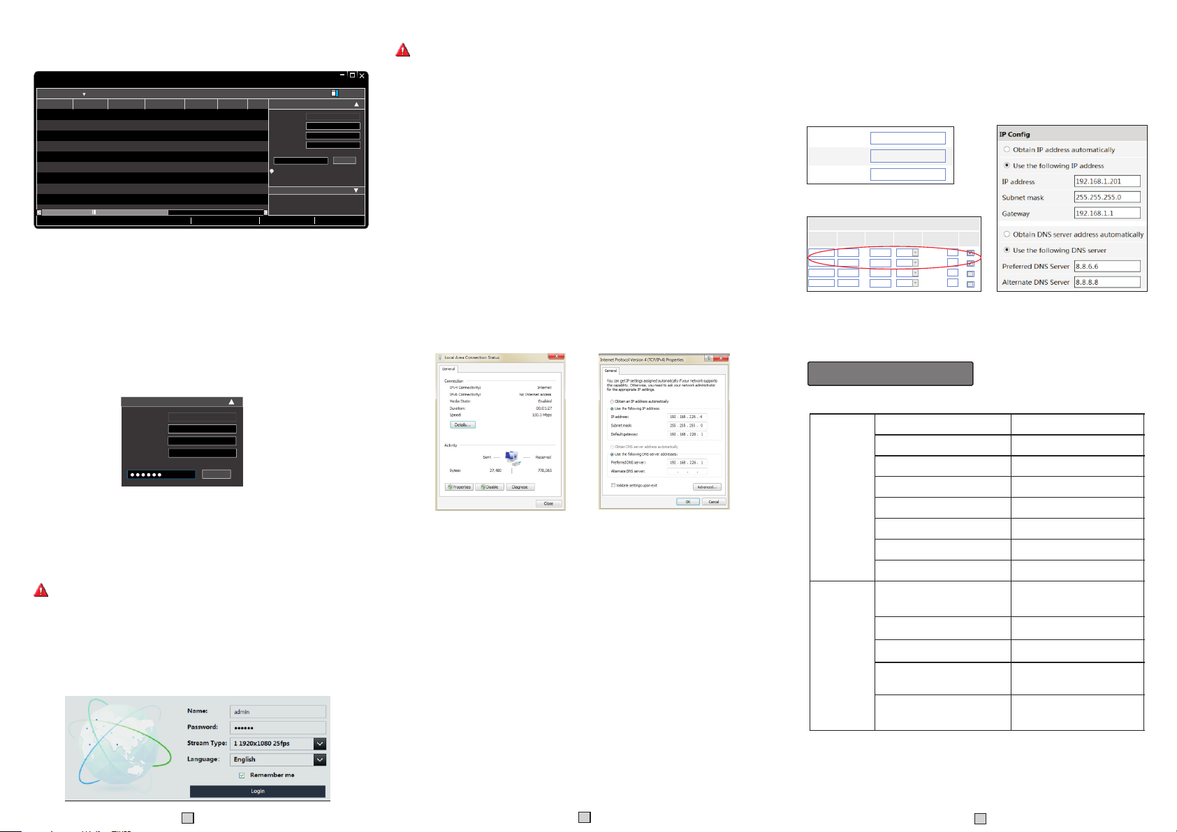
② Find the I P-Tool from the CD and then ins tall it in th e PC.
After th at, run the I P-Tool as shown be low.
Imme diate R efres h
Devi ce Name Devi ce Type IP Addr ess Htt p Port Data P ort
name
name
name
Total De vice: 3
Prod uct Mod el
unkn own
IPC
unkn own
IPC
unkn own
IPC
Dev ice Net work Se arch
192. 168.2 26.20 1
192. 168.1 .2
192. 168.1 .3
Loca l IP Addre ss:19 2.168 .1.4
80
9008
80
9008
80
9008
Subn et Mask :255. 255.2 55.0 Gate way: 19 2.168 .1.1 DNS:21 0.21. 196.6
Subn et
Modi fy Netw ork Par amete r
255. 255.
Mac Add ress
255. 255.
IP Addr ess
Subn et Mask
255. 255.
Gate way
i
Tip: E nter the a dmini strat or pass word, and
then m odify t he netw ork par amete rs.
Restore IPC Default Configuration
Abo ut
CE :98 : 23 :75 :3 5 :22
192 .1 68 . 226 . 20 1
255 . 25 5 . 255 . 0
192 .1 68 . 226 . 1
Modi fy
③ Modify the IP address. The default IP address of this camera
is 192.168.226.201. Click the information of the camera listed
in the above table to show the network information on the right
hand. Mo dify the IP address a nd gatewa y of the came ra and
make sur e its netwo rk addres s is in the sam e local network
segmen t as the comp uter’s. Please modify th e IP addre ss of
your dev ice accor ding to the p ractica l situation.
Mod ify Net work Pa ramet er
Mac Ad dress
IP Add ress
Sub net Mas k
Gat eway
CE :9 8 :23 :75 : 35 :22
192 . 168 . 1 . 201
255 . 2 55 . 255 . 0
192 . 168 . 1 . 1
Mod ify
For example, the IP address of your computer is 192.168.1.4.
So the IP address of the camera shall be changed to 192.168.1.X.
After modification, please input the password of the administrator
and click “Modify” button t o modify th e setting .
The defaul t passwor d of the administrator i s “123456 ”.
④ Double-click the IP address and then the system will pop up the IE
browser to connec t IP-CAM . IE b rowser wi ll auto dow nload
the Activ e X control. After downloading, a login window will pop
up as shown below:
Input th e user name a nd passwo rd to login .
The default username is admin; the default password is 123456.
● Directly Access Through IE
The defa ult netwo rk settin gs are as sho wn below:
IP address: 192. 168.226 .201 HTTP :80
Subnet M ask: 255. 255.255 .0 Data Por t:9008
Gatewa y: 192.16 8.226.1
You may use the above default settings when you log in the camera
for the first tim e.
① Set the IP address of the PC and the network segment should be as
the same as the default settings of IP-CAM. Open the network and
share ce nter. Clic k “Local Area Co nnectio n” to pop up th e following
window. Sel ect “Prop erties” a nd then select Interne t protoco l
accord ing to the ac tual situ ation (fo r example: IPv4). Next , click
“Prope rties” bu tton to set t he networ k of the PC.
② Open the IE Browser and input the default address of IP-CAM
and conf irm. The IE bro wser will download Acti ve X contro l
automa tically.
③ After tha t, the logi n dialog box will pop up.
④ Input the default username and password and then enter to view.
◆ WAN
Take access t he device by the router or v irtual se rver for ex ample.
① Make sur e the camer a is well con nected vi a LAN; Then log
in the cam era via LAN a nd go to the Sy stem Cong fig→Netwo rk
Config→P ort menu to s et up the por t number.
② Enter Sy stem Conf ig→Networ k Config→Wired menu to mo dify
the IP address.
③ Go to the router ’s management interface through IE browser to
forward the IP address and port of IP-CAM in the “Virtual Server”.
④ Open the I E browser a nd input it s WAN IP an d HTTP por t to
access t he IP-CAM .
HTT P Po rt
Da ta Po rt
RTS P Por t
Appl icati on
1 900 7
2 80
3 100 00
4
Port Co nf ig
Sta rt
to
to
to
210 00
to
80
9008
554
Port R ange
End Prot ocol
900 8
Both
81
Both
Both
100 01
210 01
Both
IP Addr ess
192 .168. 1. 201
192 .168. 1. 201
192 .168. 1. 166
192 .168. 1. 166
Enab le
IP Config Route r Co nfig
Preset Description
Run tra ck 1
Run cru is e 1
Run 2cruis e
Run 3cruis e
Run 4cruis e
OSD men u
Enabl e ra ndom scan
Enabl e P- PSCAN
Set ran do m scan; Task auto
call th e be ginning p oi nt
Set lef t bo rder of P-P SC AN
Set right border of P-PSCAN
Set the boundary value of the
near and middle infrared light
Set the boundary value of the
middle and far infrared light
Call Pr es et
Set Pre se t
Call No . 90 Preset
Call No . 91 Preset
Call No . 92 Preset
Call No . 93 Preset
Call No . 94 Preset
Call No . 95 Preset
Call No . 97 Preset
Call No . 99 Preset
Set No. 9 1 Preset
Set No. 9 2 Preset
Set No. 9 3 Preset
Set No.94 Preset three times
Set No.95 Preset three times
4
5
6
450043000245 A0
 Loading...